Article

Vacuum Brazing of 55 vol.% SiCp/ZL102 Composites Using Micro-Nano Brazing Filler Metal Fabricated by Melt-Spinning

1
School of Materials Science and Engineering, Henan Polytechnic University, Jiaozuo 454003, China
2
State Key Laboratory of Advanced Welding and Joining, Harbin Institute of Technology, Harbin 150001, China
3
Henan Jingtai High-Novel Materials Ltd. of Science and Technology, Jiaozuo 454003, China
*
Author to whom correspondence should be addressed.
Metals 2020, 10(11), 1470; https://doi.org/10.3390/met10111470
Submission received: 17 September 2020 / Revised: 24 October 2020 / Accepted: 27 October 2020 / Published: 4 November 2020
(This article belongs to the Special Issue Advances in Physical Metallurgy)

Abstract

:
The joining methods of Aluminum matrix composites reinforced with SiC particles (SiCp/Al MMCs) are a challenge during the manufacturing process due to the significant differences between SiC particles and base aluminum in terms of both physical and chemical properties. Micro-nano brazing filler metal Al-17.0Cu-8.0Mg fabricated by melt-spinning technology was employed to deal with the joining problem of 55 vol.% SiCp/ZL102 composites in this work. The result indicated that the foil-like brazing filler metal contained uniformed cellular nano grains, with a size less than 200 nm. The solidus and liquidus temperatures of the foil-like brazing filler metal decreased by 4 °C and 7 °C in comparison with the values of the as-cast brazing filler metal due to the nanometer size effect. The maximum joint shear strength of 98.17 MPa achieved with a brazing temperature of 580 °C and holding time of 30 min was applied in vacuum brazing process. The width of the brazing seam became narrower and narrower with increasing brazing temperature owning to the strong interaction between the micro-nano brazing filler metal and 55 vol.% SiCp/ZL102 composites. The fracture morphology of the joint made at a brazing temperature of 580 °C was characterized by quasi-cleavage fracture. After brazing, the chemical concentration gradient between the brazing filler metal and base material disappeared.

1. Introduction

Aluminum matrix composites reinforced with SiC particles (SiCp/Al MMCs) have attracted more and more attention from researchers around the world because of their excellent performances such as high specific stiffness and specific strength, low thermal expansion coefficient, good radiation resistance, and so on [1,2,3,4]. In recent years, SiCp/Al MMCs have been widely used in aerospace, weaponry, and electronics industries [5,6,7,8]. SiCp/Al MMCs are also favored in the field of electronic packaging due to their high dimensional stability and thermal conductivity. However, the joining methods of SiCp/Al MMCs are still a challenge for researchers during the manufacturing process due to the significant differences between SiC particles and base aluminum in terms of both physical and chemical properties, which severely limit the promotion and application of SiCp/Al MMCs [9,10,11,12].
At present, joining methods of SiCp/Al MMCs mainly focus on fusion welding [13,14,15], diffusion welding [16,17], and brazing [18,19,20]. However, it is difficult to obtain high-quality welded joints by those conventional joining methods. For example, when fusion welding was applied to SiCp/Al MMCs, the segregation of SiC particles appeared in a molten pool due to the poor liquidity. In addition, a mass of brittle phases such as Al4C3 would be generated at the weld seam [21,22]. Wang X.H. [23] et al. conducted TIG welding on 15 vol.% SiCp/6061Al composites and found that the brittle phase of Al4C3 was formed when SiC particles reacted with base Al at high temperature. In order to reduce the heat input, Pichumani S. [24] et al. used pulse current TIG welding during the welding of 8 vol.% SiCp/Al composites. However, the Al4C3 phase was still produced during the welding, which significantly affected the performance of the welded joint. When diffusion welding was used to weld high-volume fraction SiCp/Al MMCs, the aluminum oxide film produced during the welding process was difficult to remove, which damaged the continuity of the SiC particle-reinforced phase. More importantly, diffusion welding requires a stricter welding sample size and shape. As a consequence, it is hard to employ diffusion welding to satisfy the complex engineering applications of SiCp/Al MMCs [25,26]. Brazing has the characteristics of a low welding temperature, uniform heating of the welding sample, and less thermal deformation. Therefore, it is considered to be one of the most effective joining methods for welding high-volume fraction SiCp/Al MMCs. To braze SiCp/Al composites, Wu M. [27] et al. reduced the melting point of brazing filler metal by adding elements Ni and Cu into Al-Si eutectic brazing filler metal, which made the brazing temperature lower and increased the joint performance. Wang P. [28] et al. used active brazing filler metal Al-12Si-1.5Mg-4Ti to braze nickel-plated SiCp/Al MMCs and found that the active brazing filler metal had strong wettability to SiCp/Al MMCs. Bangash, M.K. [29] et al. used Al-Cu-Mg and Al-Si-Mg-Ti two aluminum-based brazing filler metals to braze Al-6016 aluminum alloy plates and aluminum alloy foams. It was found that the Al-Cu-Mg amorphous brazing filler metal had higher diffusion into the alloy than the Al-Si-Mg-Ti amorphous bonding alloy. Gao Z. [30] et al. added Ni to Al-Cu-Mg brazing filler metal for brazing SiCp/Al MMCs. A brazed joint with better performance, better wettability, and fluidity was obtained. It is very important to improve the wettability between the brazing filler metal and SiCp/Al MMCs by selecting the appropriate alloying elements.
It is well known that SiCp/Al MMCs oxidize easily in the atmosphere environment due the strong affinity between aluminum and oxygen; the resulting oxide film limits the wetting and spreading of the brazing filler metal, which makes it difficult to form high-quality brazed joints. In view of this, a self-developed micro-nano foil-like brazing filler metal was utilized in this research to braze 55 vol.% SiCp/ZL102 composites in a vacuum environment. The thermodynamic properties, microstructural characteristics and phase composition of the brazing filler metal produced by melt-spinning technology were studied primarily. Different brazing temperatures were applied in this research to evaluate the influence of a micro-nano sized brazing filler metal on the microstructure evolution, element distribution, and mechanical property of the joints. The fracture morphology of the brazed joint at the optimal brazing temperature was investigated as well. This research provides a new possible means for the joining of high-volume fraction SiCp/Al MMCs.

2. Materials and Methods

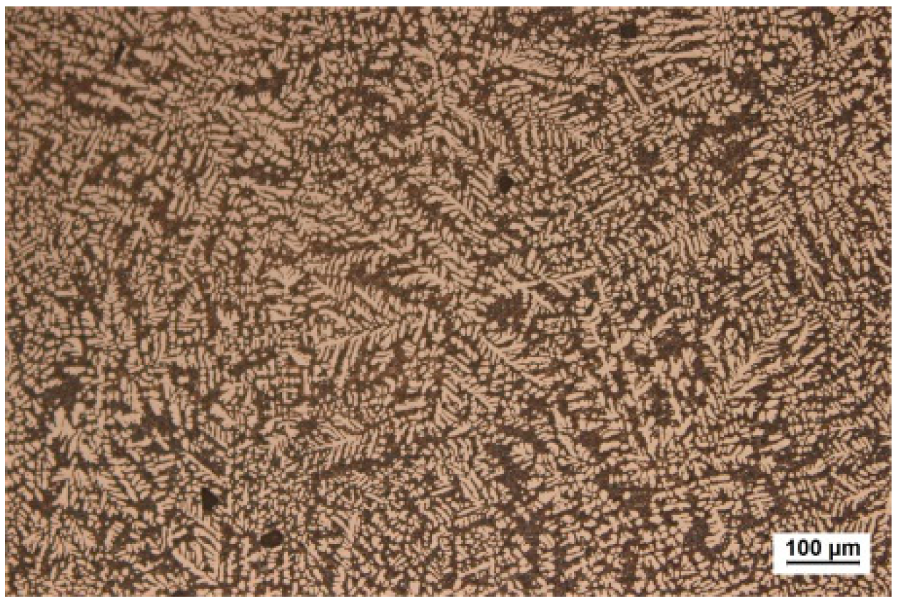
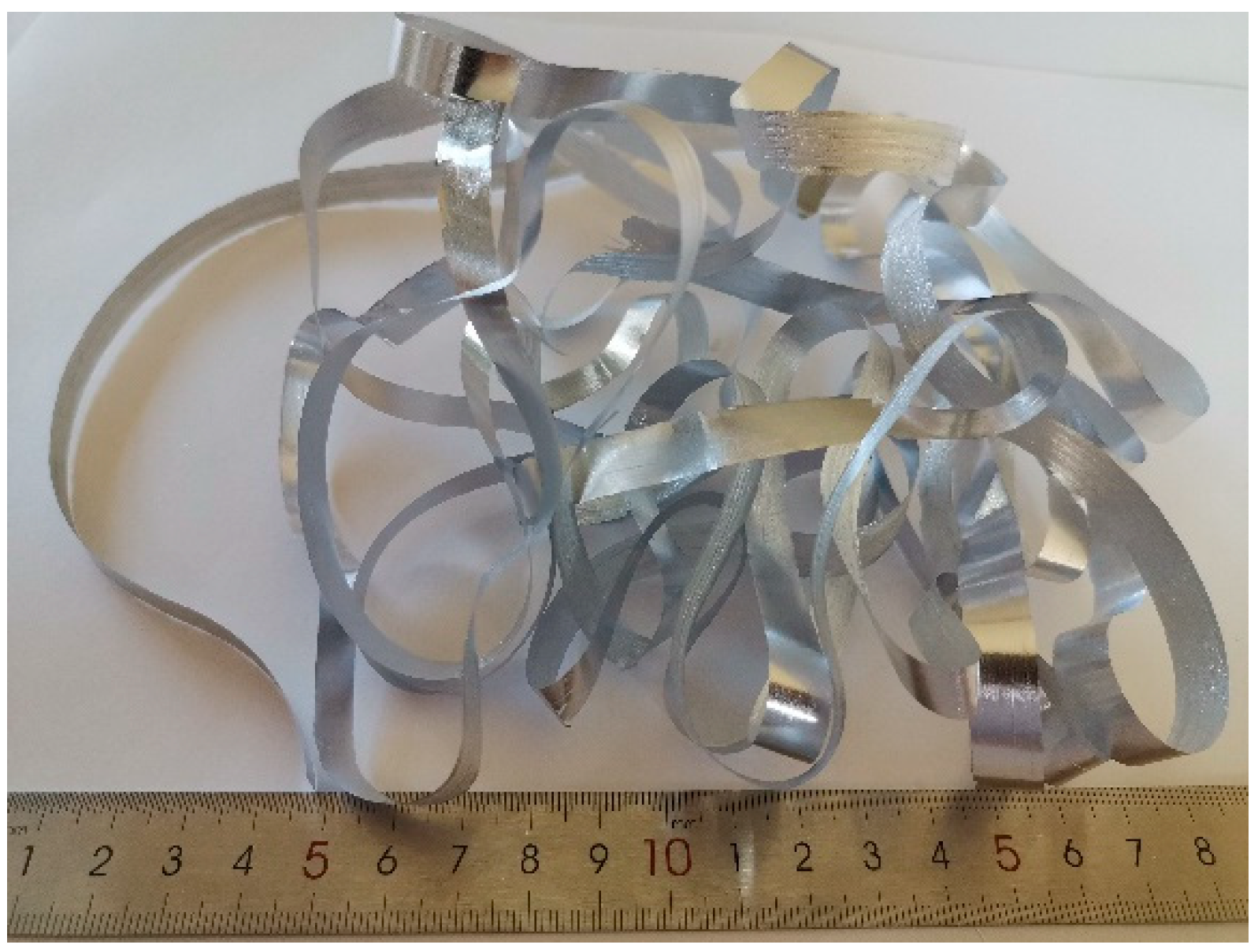
In this experiment, 55 vol.% SiCp/ZL102 composites made by pressureless infiltration technology were used as brazing specimen. The microstructure is shown in Figure 1 and was composed of SiC particles with 55% volume and a ZL102 aluminum alloy matrix. The chemical composition of the ZL102 aluminum alloy is shown in Table 1. Brazing specimens with the size of 20 mm × 10 mm × 2 mm were cut by a wire cut electric discharge machine (DK7745, Suzhou Baojun CNC Equipment Co., Ltd., Suzhou, China). To prepare the micro-nano brazing filler metal, pure Al and Cu, as well as an Al50-Mg master alloy with a purity of 99.99% were melted in a vacuum induction furnace and cast in an iron mold three times to remove impurities in the raw materials. After smelting, the as-cast brazing filler metal alloy with the chemical composition of Al-17.0Cu-8.0Mg was obtained. The metallographic structure of the as-cast brazing filler metal is shown in Figure 2. Then, the as-cast brazing filler metal alloy was moved into the quartz glass tube in a melt-spinning machine. The melt-spinning was also carried out in a vacuum environment with a vacuum degree of 2.0 × 10⁻² Pa. In order to obtain defect-free and micro-nano sized foil-like brazing filler metal, the rotational speed of the copper roller was set to 1400 r/min, and the argon injection pressure in the quartz glass tube was set to 0.02 MPa. The prepared foil-like brazing filler metal with thickness of 70 μm and width of 10 mm is shown in Figure 3.
The 55 vol.% SiCp/ZL102 composites should be pretreated before vacuum brazing due to the presence of oxidation film and oil stains on the surface of composites. The process was as follows: first of all, the joining surfaces of the specimen were polished by 800# sandpaper. Secondly, the polished specimens were put into a bath filled with a 1:1 mixture of alcohol-acetone and then the specimens were cleaned ultrasonically for 10 min. Subsequently, the cleaned brazing specimens were corroded in 7% NaOH solution for 30 s, and then placed in 5% HNO3 solution for 60 s. Finally, the brazing specimens were washed with ultrasonic water for 10 min. After pretreatment, the assembled overlap joints with the brazing filler metal were joined in a vacuum furnace (ZHS-60, China Electronics Technology Group Corporation, Taiyuan, China). Figure 4 shows the schematic diagram of the brazing joint. During the brazing, a pressure of 0.01 MPa was applied to the sandwich specimen. Based on thermodynamic properties of the brazing filler metal and characteristic of SiCp/ZL102 composites, the brazing temperature was set to be within the range of 560 °C to 600 °C, the brazing time was set to 30 min, and the heating rate was 10 °C/min. Heating started when the vacuum was lower than 5 × 10⁻³ Pa, and cooling started after brazing. The cooling rate was 3 °C/min, and the sandwich specimen was taken out when cooled to below 180 °C.
Before the vacuum brazing, thermodynamic properties of the as-cast and foil-like brazing filler metal were analyzed by differential scanning calorimetry (DSC) used a thermal analyzer (Setaram Evolution 2400, Global (Hong Kong) Technology Co., Ltd., Hong Kong, China). The temperature was raised to 600 °C at a rate of 10 °C/min. The phase composition of the foil-like brazing filler metal was analyzed by using a D8 ADVANCE X-ray diffractometer (Bruker, Karlsruhe, Baden-Wurttemberg, Germany). During XRD measurements, Cu-Kα radiation was utilized with the following test conditions: tube voltage of 40 kV, tube current of 150 mA, scanning angle of 10–90°, step size of 0.02°, and scanning speed of 10°/min. After the brazing process, the joints were polished by 400~1000# sandpaper. The metallographic structure of the brazed joint was observed by an optical microscope (OLYMPUS-CK40M, Shanghai Bajiu Industrial Co., Ltd., Shanghai, China). The shear strength of the brazed joint was tested on a universal electronic testing machine (CMT5205, MTS Systems (China) Co., Ltd., Shenzhen, China), and the shear rate was set to 0.1 mm/min. Observations of the microstructure and fracture morphology of brazed joints were carried out by a scanning electron microscope (Carl Zeiss NTS GmbH, Merlin Compact, Jena, Thuringia, Germany), secondary electron imaging (SEM) and the composition and diffusion of the elements in brazed joints were analyzed by energy-dispersive X-ray spectroscopy (EDS).

3. Results and Discussion

3.1. Thermodynamic Property and Microstructural Characteristics of the Brazing Filler Metal

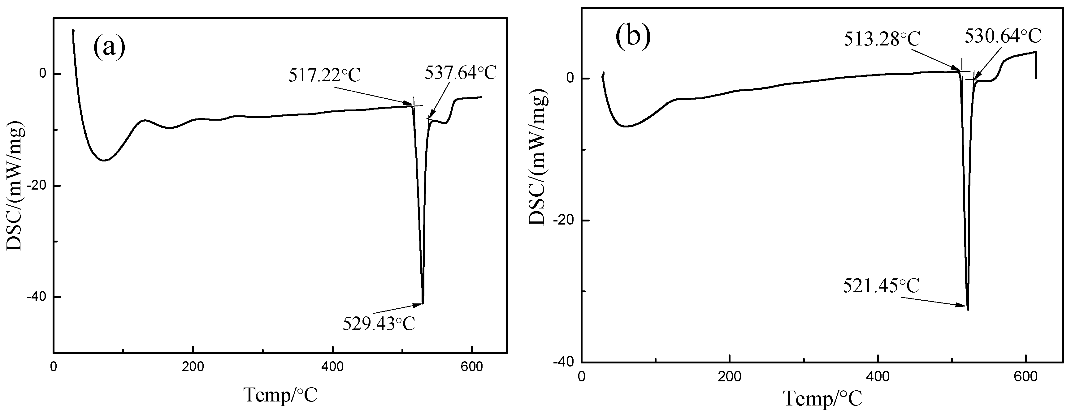
The DSC curve of the brazing filler metal before and after the melt-spinning process is shown in Figure 5. Figure 5a is a DSC curve of the as-cast brazing filler metal made by the high-frequency induction melting furnace, and Figure 5b shows the DSC curve of the foil-like brazing filler metal made by melt-spinning technique characterized with an extremely rapid cooling rate. It can be found from Figure 5 that the solidus and liquidus temperatures of the foil-like brazing filler metal decreased by 4 °C and 7 °C in comparison with the values of the as-cast brazing filler metal. The corresponding molten temperature region decreased by 3 °C. The decrease of the thermodynamic temperature was related to the grain size. The melt-spinning technique can refine the grain size significantly due to the rapid cooling rate.
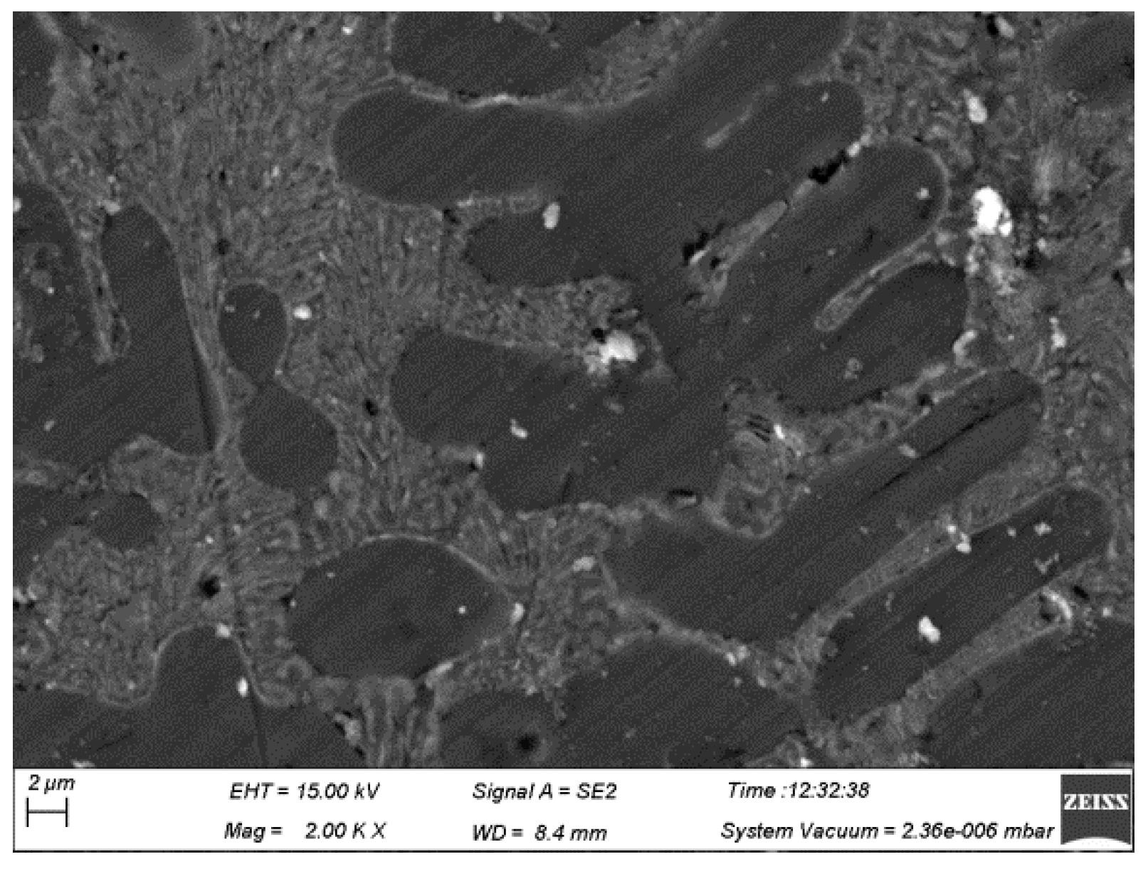
Figure 6 shows the microstructure of the traditional as-cast brazing filler metal viewed under a scanning electron microscope. It can be seen that there were many cell crystals and dendrites in the as-cast brazing filler metal, and some areas had defects such as pores, and the grain size in the as-cast brazing filler metal was large. The melt-spinning technology can produce the microstructures which can vary greatly from those formed in traditional slow-cooled bulk material. Figure 7 shows the microstructure of the foil-like brazing filler metal made by the melt-spinning technique. The side of the foil-like brazing filler metal contacting the copper roller was called the near-roller surface while the other side was called the free surface. Figure 7a displays the microstructure foil-like brazing filler metal at the free surface; the average grain size is about 159.09 nm, and Figure 7b displays the microstructure at the near-roller surface; the average grain size is about 129.63 nm. Figure 7 indicated that there was no microdefect such as micro-voids and element segregation in the foil-like brazing filler metal. It can be known from the microstructure that foil-like brazing filler metal mainly contained uniform cellular nano grains, and the sizes of the cellular grains were less than 200 nm, which had the characteristics of nanomaterials. As shown in Figure 7, the grain size at the near-roller surface was smaller than that at the free surface due to the faster cooling rate. The results showed that owing to its small size and high surface free energy, the chemical potential of the foil-like brazing filler metal containing micro-nano grains was much higher than that of the bulk material. As a result, the melting point of the micro-nano sized brazing filler metal was depressed in comparison to that of the bulk crystals. Compared with the brazing filler metal prepared by conventional methods, there was a lower melting point and better diffusibility. High-quality brazing joints can be obtained when micro-nano sized brazing filler metal was utilized in experiment.
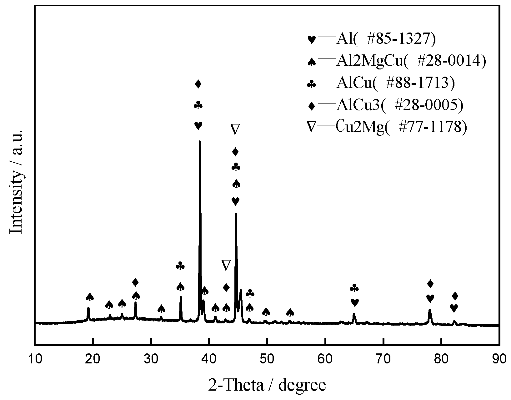
Figure 8 is the X-ray diffraction analysis (XRD) curve of the foil-like brazing filler metal, which indicates that there are mainly five kinds of phases: α-Al, Al2MgCu, AlCu, AlCu3 and Cu2Mg, and the content of the Al2MgCu phase is relatively high. Due to the high chemical activity at elevated temperature, alloying elements Mg and Cu in filler metal were mainly in the form of intermetallic compounds. Combined with the analysis in Figure 7, we can infer that the sizes of intermetallic compounds were limited to the nanoscale. Those intermetallic compounds distributed in α-Al were very uniform due to the rapid cooling rate during manufacturing.

3.2. Microstructure and Element Distribution Analysis of Brazed Joints

Figure 9 shows the optical microstructure evolution of 55 vol.% SiCp/ZL102 composites joints made in a brazed temperature range of 560 °C to 600 °C by using micro-nano foil-like brazing filler metal Al-17.0Cu-8.0Mg. As shown in Figure 9a, some small defects such as an unwetted area and micro-void between the filler metal and SiC particle existed at the interface, which had significant effect on the joint mechanical property. The reason for that was the wettability and interaction between the filler metal and composites was very weak at a lower brazing temperature of 560 °C on account of the lower atomic activity. Figure 9 indicated that brazed joints were continuous and tightly bonded, without physical defects such as micro-voids and cracks when the brazing temperature exceeded 570 °C. The interaction between the filler metal and composites was enhanced under the condition of a relatively high brazing temperature. It can be seen in Figure 9b–e that a gray needle-like or massive eutectic Si structure appeared in the center of the brazing seam. As shown in Figure 9e, the quantity of eutectic Si in the brazing seam was almost as much as in composites. This was due to the large number of Si elements in the base material, which diffused into the brazing joint during the brazing process and formed the eutectic structure with Al elements in the brazing joint [31]. This indicated that a strong interaction between the micro-nano brazing filler metal and 55 vol.% SiCp/ZL102 composites occurred. Consequently, the width of the brazing seam became narrower and narrower with the increase in the brazing temperature.
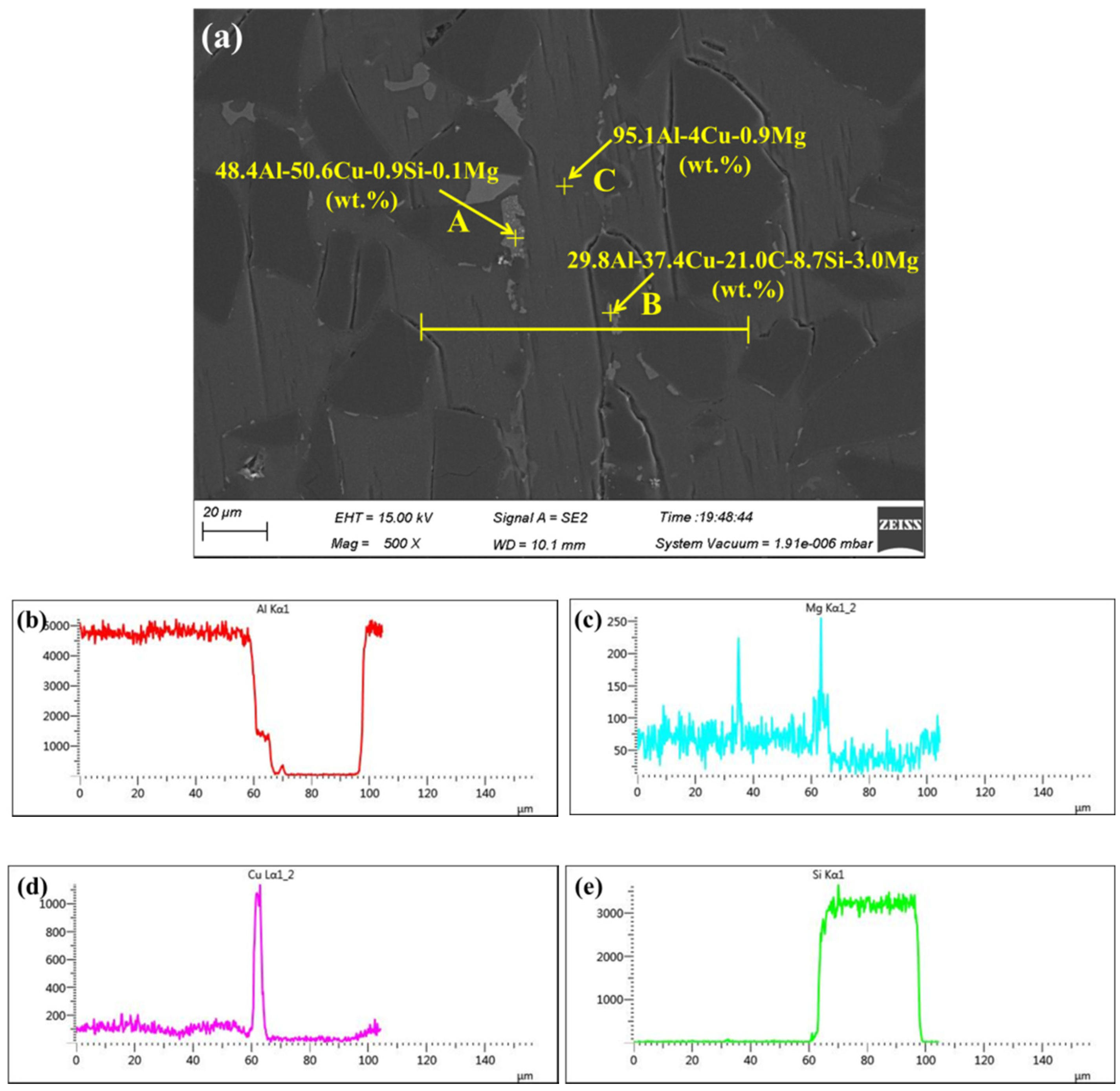
SEM image of a typical region at the interface of the 55 vol.% SiCp/ZL102 composite joint made at 580 °C and corresponding energy dispersive X-ray analysis are presented in Figure 10. Figure 10 was taken in secondary electron mode. It can be clearly observed that there were two kinds of interfaces: the interface between the brazing filler metal and aluminum matrix, as well as the other interface between the brazing filler metal and SiC particle. Figure 10a indicated that the combination of the two type of interfaces was quite compact. The chemical composition of the joint was analyzed using EDS, as shown in Figure 10a. Some white block phases appeared near the brazing seam. Testing points A and B were located at the center of these white block phases. At point A, the chemical composition was measured as 48.4Al-50.6Cu-0.9Si-0.1Mg (wt.%). At point B, the chemical composition was measured as 29.8Al-37.4Cu-21.0C-8.7Si-3.0Mg (wt.%). Elements of Al and Cu were the primary composites in these white regions. At point B, a small amount of Mg was included which may form the AlMgCu intermetallic. Moreover, these white block phases were mainly distributed around the SiC particle, which meant that the interface between the SiC particle and aluminum was the main diffusion path for Cu. The white block phase can be found at the top left corner in Figure 10a. This suggested that the diffusion distance of element Cu exceeded at least 100 μm under the brazing temperature of 580 °C, which can reduce the effects of brittle intermetallic compounds such as Al2Cu and AlCu in the brazing seam. At point C, the chemical composition was measured as 95.1Al-4.0Cu-0.9Mg (wt.%). Al was the primary composite in the brazing seam. The content of Cu and Mg in this area was much lower than that in the original brazing filler metal (Al-17.0Cu-8.0Mg). Figure 10b–e display the individual elemental line scanning profile of Al, Mg, Cu, and Si, respectively. As can be seen, the distributions of elements Al, Mg, Cu, and Si were quite homogeneous except the areas of the white block phase and SiC particle. After brazing, the chemical concentration gradient between the brazing filler metal and base material disappeared. The line scanning profile also indicated that the inter-diffusion phenomenon between the brazing filler metal and 55 vol.% SiCp/ZL102 composites occurred intensively.
Under the condition of high temperature, Mg was more active than Al, which made it have the possibility to react with alumina on the surface of SiCp/Al MMCs [32], as shown in Equation (1).
3 Mg + Al 2 O 3 = 3 MgO + 2 Al
That reaction can eliminate some part of dense alumina, which will improve the wettability of the brazing filler metal. Through the energy spectrum analysis in Figure 10a, it can be seen that the content of Mg in the joint was much lower than that in the original brazing filler metal. As is known, Mg has a quite high saturated vapor pressure compared to the other elements, such as Al, Cu, Fe, etc. During the course of vacuum brazing, the volatile Mg was gradually vaporized and accumulated. A part of the accumulated Mg vapor broke the aluminum oxide film covering on the surface of SiCp/Al MMCs and then was discharged. As a consequence, the liquid brazing filler metal could diffuse into the base material along the broken location of the aluminum oxide film. Therefore, the chemical composition balance between the brazing seam and base material was achieved.

3.3. Mechanical Properties of Brazed Joints

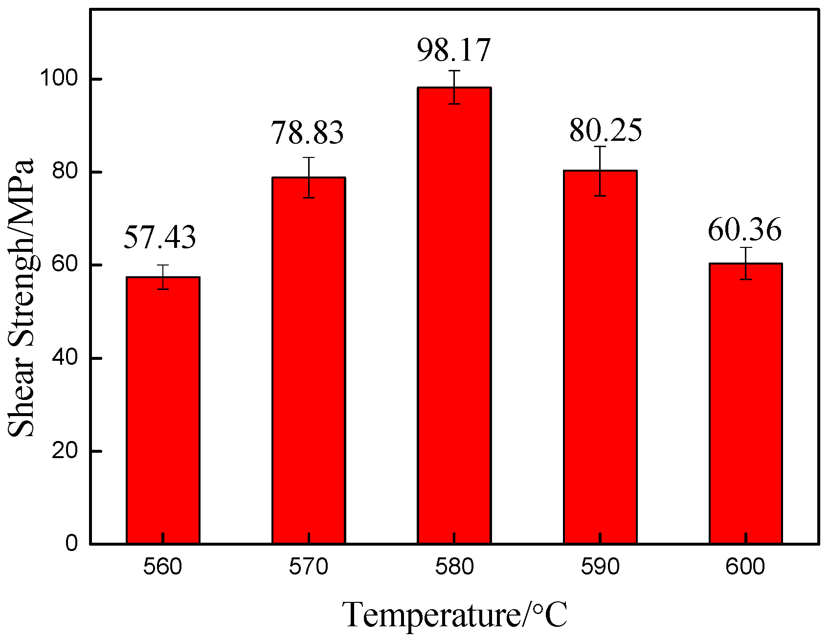
To find out the optimal process parameters, the effect of brazing temperature on the mechanical property of the joint was investigated, as displayed in Figure 11. Five specimens were tested for each brazing condition to obtain the average shearing data. The joint shear strength increased with the increasing in brazing temperature from 560 °C to 580 °C. At a brazing temperature of 560 °C, the joint shear strength was only 57.43 MPa due to the insufficient diffusion between the brazing filler metal and the matrix, shown from the analysis in Figure 9a. The maximum shear strength of the joint was 98.17 MPa at the brazing temperature of 580 °C. For vacuum brazing, mutual diffusion has to abide by the Arrhenius equation expressed in Equation (2), which is the diffusion coefficient of the filler materials. As can be seen, the diffusion coefficient D(T) is a function of temperature (T), which is a process parameter and can be controlled during the experiment.
D ( T ) = D 0 exp ( Q R T )
where T is the diffusion brazing temperature, Q the activation energy, R the gas constant, and D0 the diffusion constant.
With the temperature increase, the diffusion coefficient of elements in the brazing system will increase significantly. However, a further increase in the brazing temperature to 590 °C and 600 °C caused a decrease of shear strength to 80.25 MPa and 60.36 MPa, respectively. The change in shear strength at that high temperature was due to the excessive interaction of elements in the joint and matrix, which caused the generation and growth of brittle intermetallics such as Al2Cu and AlCu having a remarkable influence on the shear strength. On the other hand, a small part of liquid aluminum effused from the 55 vol.% SiCp/ZL102 composites during the course of vacuum brazing when the brazing temperature of 600 °C was utilized. This phenomenon had a considerable negative effect on the joint shear strength and mechanical property of 55 vol.% SiCp/ZL102 composites.

3.4. Fracture Analysis of Brazed Joints

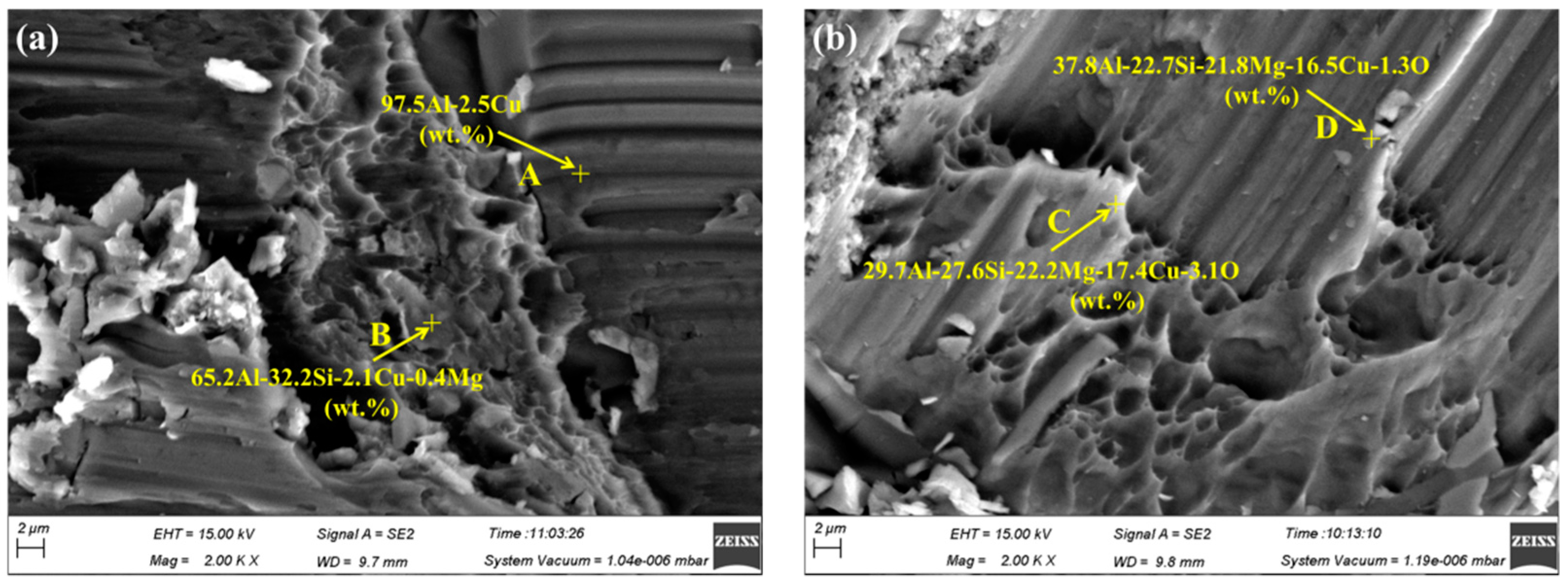
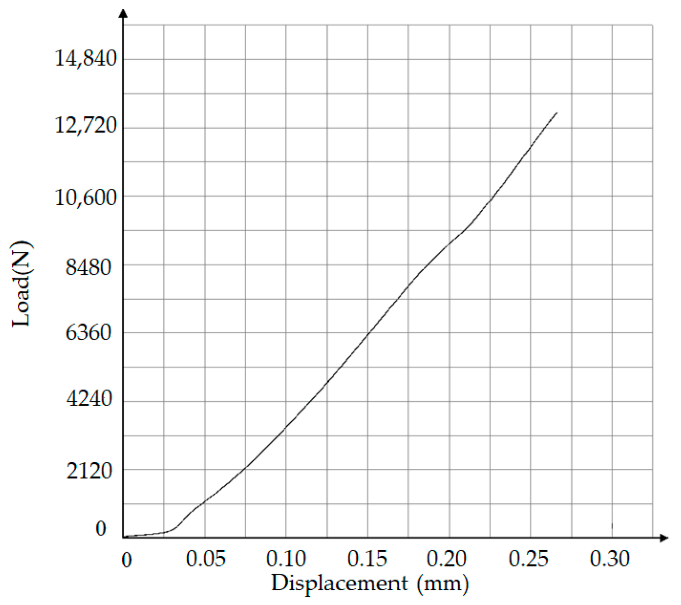
Figure 12 displays the typical scanning fracture morphology and EDS analysis of the joint made using micro-nano brazing filler metal Al-17.0Cu-8.0Mg at a temperature of 580 °C and holding time of 30 min after room temperature shear testing. As can be seen in Figure 12, both sides of the joint fracture were characterized by the quasi-cleavage fracture. No SiC particles can be found in fracture surface, which meant that the fracture occurred in the brazing seam rather than the interface between the brazing filler metal and 55 vol.% SiCp/ZL102 composites. Using EDS analysis, the chemical composition of point A was measured to be 97.5Al-2.5Cu (wt.%). It indicated that the scratching area in the fracture was mainly composed of aluminum solid solution, having good plasticity. The chemical composition in the cleavage fracture area, such as point B, C, and D was composed of elements of Al, Si, Cu, and Mg, which were 65.2Al-32.2Si-2.1Cu-0.4Mg (wt.%), 29.7Al-27.6Si-22.2Mg-17.4Cu-3.1O (wt.%), and 37.8Al-22.7Si-21.8Mg-16.5Cu-1.3O (wt.%), respectively. The only source of element Si was 55 vol.% SiCp/ZL102 composites. As can be seen in Figure 12, the Si content at points B, C, and D exceeded 22.7 wt.%, which signified that interdiffusion between the micro-nano brazing filler metal and 55 vol.% SiCp/ZL102 composites took place sufficiently during the course of vacuum brazing. The intermetallic compound phases (IMC) such as Mg2Si, Al2Cu, and Cu2Mg would be formed due to the high activity of the micro-nano brazing filler metal at high temperature. During vacuum brazing, the formation of brittle IMC would cause stress concentration around the IMC interface. In the following shearing test, the joint was easily cracked in this area of stress concentration. However, the fracture appearance demonstrated that there was no large blocked IMC in the joint, and this would be very beneficial in terms of increasing the joint mechanical property. To better analyze the fracture mechanism of brazed joints, Figure 13 shows the shear curve with temperature of 580 °C and holding time of 30 min. The force-displacement curve was relatively smooth and there was no yield phenomenon. Therefore, the brazing joint is a brittle fracture.

4. Conclusions

In this work, 55 vol.% SiCp/ZL102 composites were successfully bonded through the brazing process under a vacuum condition. Micro-nano brazing filler metal Al-17.0Cu-8.0Mg fabricated by melt-spinning technology was utilized for brazing in a temperature range of 560–600 °C, with a holding time of 30 min. This new micro-nano brazing filler metal and corresponding brazing process can provide a technical reference and theoretical value for dealing with the joining problem of SiCp/Al MMCs. The main conclusions can be summarized as following:
(1)
Using melt-spinning technology, the foil-like brazing filler metal Al-17.0Cu-8.0Mg was obtained. The microstructure analysis indicated that the foil-like brazing filler metal mainly contained uniformed cellular nano grains, with a size less than 200 nm. The solidus and liquidus temperatures of the foil-like brazing filler metal decreased by 4 °C and 7 °C in comparison with the values of the as-cast brazing filler metal due to the nanometer size effect. Compared with the brazing filler metal prepared by conventional methods, the micro-nano brazing filler metal had higher toughness, lower melting point, and better diffusibility, which were more conducive to the wetting and spreading behavior between the brazing filler metal and base material.
(2)
The microstructure observation indicated that brazed joints were continuous and tightly bonded, without physical defects such as micro-voids and cracks when the brazing temperature exceeded 570 °C. Moreover, the width of the brazing seam became narrower and narrower with increasing brazing temperature owning to the strong interaction between the micro-nano brazing filler metal and 55 vol.% SiCp/ZL102 composites. Some white block phases mainly containing elements Al and Cu appeared near the brazing seam. The main diffusion path for Cu was the interface between the SiC particle and aluminum. After brazing, the chemical concentration gradient between the brazing filler metal and base material disappeared.
(3)
The maximum joint shear strength was achieved at 98.17 MPa at the brazing temperature of 580 °C. The joint shear strength increased in the temperature range of 560 °C to 580 °C. However, a further increase in the brazing temperature to 590 °C and 600 °C caused a decrease in shear strength to 80.25 MPa and 60.36 MPa, respectively. The excessive interaction in the joint and matrix caused the generation and growth of brittle intermetallics such as Al2Cu and AlCu having a remarkable influence on the shear strength.
(4)
The fracture morphology of the joint made at a brazing temperature of 580 °C was characterized by quasi-cleavage fracture. Fractures occurred in the brazing seam rather than the interface between the brazing filler metal and 55 vol.% SiCp/ZL102 composites since no SiC particles could be found in the fracture surface. There was no large blocked intermetallic compound in the joint, and this would be very beneficial in terms of increasing the joint mechanical properties.

Author Contributions

Investigation, D.Q., Z.G., and X.B.; resources, Z.W.; supervision, J.N.; writing—original draft preparation, D.Q.; writing—review and editing, Z.G. and J.N. All authors have read and agreed to the published version of the manuscript.

Funding

The research was financially supported by the National Natural Science Foundation of China (No. 51245008), the Science and Technology Project of Henan Province, China (No. 202102210036), and the Fundamental Research Funds for the Universities of Henan Province, China (No. NSFRF180405).

Conflicts of Interest

The authors declare no conflict of interest.

References

  1. Arami, H.; Simchi, A.; Reihani, S.M.S. Mechanical induced reaction in Al-CuO system for in-situ fabrication of Al based nanocomposites. J. Alloys Compd. 2008, 465, 151–156. [Google Scholar] [CrossRef]
  2. Lakra, S.; Bandyopadhyay, T.K.; Das, S.; Das, K. Synthesis and characterization of in-situ (Al-Al3Ti-Al2O3)/Al dual matrix composite. J. Alloys Compd. 2020, 842, 155–745. [Google Scholar] [CrossRef]
  3. Hekner, B.; Myalski, J.; Valle, N.; Botor-Probierz, A.; Sopicka-Lizer, M.; Wieczorek, J. Friction and wear behavior of Al-SiC(n) hybrid composites with carbon addition. Compos. Part B Eng. 2017, 108, 291–300. [Google Scholar] [CrossRef]
  4. Beffort, O.; Long, S.Y.; Cayron, C.; Kuebler, J.; Buffat, P.A. Alloying effects on microstructure and mechanical properties of high volume fraction SiC-particle reinforced Al-MMCs made by squeeze casting infiltration. Compos. Sci. Technol. 2007, 67, 737–745. [Google Scholar] [CrossRef]
  5. Wang, T.; Wu, X.; Zhang, G.; Dai, Y.; Xu, B.; Ruan, S. An experimental study on single-point diamond turning of a 55 vol% SiCp/Al composite below the ductile brittle transition depth of SiC. Int. J. Adv. Manuf. Technol. 2020, 108, 2255–2268. [Google Scholar] [CrossRef]
  6. Amirkhanlou, S.; Niroumand, B. Development of Al356/SiCp cast composites by injection of SiCp containing composite powders. Mater. Des. 2011, 32, 1895–1902. [Google Scholar] [CrossRef]
  7. Haghayeghi, R.; Kapranos, P. An investigation on physical and chemical refinement of aerospace aluminium alloys. Mater. Lett. 2013, 95, 121–124. [Google Scholar] [CrossRef]
  8. Dursun, T.; Soutis, C. Recent developments in advanced aircraft aluminium alloys. Mater. Des. 2014, 56, 862–871. [Google Scholar] [CrossRef]
  9. Lei, Y.; Nie, J.J.; Chen, X.; Zhang, Z. Effect of Ti-Al on microstructures and mechanical properties of plasma arc in-situ welded joint of SiCp/Al MMCs. Trans. Nonferrous Met. Soc. China 2008, 18, 809–813. [Google Scholar] [CrossRef]
  10. Niu, J.; Luo, X.; Tian, H.; Brnic, J. Vacuum brazing of aluminium metal matrix composite (55 vol.% SiCp/A356) using aluminium-based filler alloy. Mater. Sci. Eng. B Adv. 2012, 177, 1707–1711. [Google Scholar] [CrossRef]
  11. Yu, Y.; Xu, D.; Tian, J.; Wang, D.; Wang, P.; Niu, J. Effects of Al-8.5Si-25Cu-xY filler metal foils on vacuum brazing of SiCp/Al composites. Mater. Sci. Technol. 2018, 34, 429–439. [Google Scholar] [CrossRef]
  12. Grilo, J.; Puga, H.; Carneiro, V.H.; Tohidi, S.D.; Barbosa, F.V.; Teixeira, J.C. Effect of Hybrid Ultrasonic and Mechanical Stirring on the Distribution of m-SiCp in A356 Alloy. Metals 2020, 10, 610. [Google Scholar] [CrossRef]
  13. Storjohann, D.; Barabash, O.M.; Babu, S.S.; David, S.A.; Sklad, P.S.; Bloom, E.E. Fusion and friction stir welding of aluminum-metal-matrix composites. Met. Mater. Trans. A 2005, 36, 3237–3247. [Google Scholar] [CrossRef]
  14. Khodabakhshi, F.; Gerlich, A.P. On the stability, microstructure, and mechanical property of powder metallurgy Al-SiC nanocomposites during similar and dissimilar laser welding. Mat. Sci. Eng. A 2019, 759, 688–702. [Google Scholar] [CrossRef]
  15. Hynes, N.R.J.; Prabhu, M.V.; Nagaraj, P. Joining of hybrid AA6063-6SiC(p)-3Gr(p) composite and AISI 1030 steel by friction welding. Def. Technol. 2017, 13, 338–345. [Google Scholar] [CrossRef]
  16. Maity, J.; Pal, T.K.; Maiti, R. Transient liquid phase diffusion bonding of 6061-15 wt% SiCp in argon environment. J. Mater. Process. Technol. 2009, 209, 3568–3580. [Google Scholar] [CrossRef]
  17. Chen, B.; Chen, Z.; Du, Z.; Zhang, G. Application of AlMgGaLi foil for joining copper to SiCp/Al-MMCs for high-temperature and high-power electronics. Appl. Phys. A Mater. 2019, 125. [Google Scholar] [CrossRef]
  18. Xiao, J.; Li, S.; Bai, S.; Yan, J.; Xiong, D.; Tang, Y. Compression brazing of SiCp/Al composite using a semisolid Zn-Al-Cu filler metal based on the strain-induced melt activation process. JOM 2019, 71, 4931–4939. [Google Scholar] [CrossRef]
  19. Weis, S.; Elssner, M.; Wielage, B.; Wagner, G. Wetting behavior of AlAgCu brazing filler on aluminum matrix composites and stainless steel. Weld World 2017, 61, 383–389. [Google Scholar] [CrossRef]
  20. Zhang, Y.; Yan, J.C.; Chen, X.G.; Cui, Y. Ultrasonic dissolution of brazing of 55% SiCp/A356 composites. Trans. Nonferrous Met. Soc. China. 2010, 20, 746–750. [Google Scholar] [CrossRef]
  21. Gao, Z.; Yang, H.; Feng, J.; Ji, F.; Niu, J.; Brnic, J. Flux-free diffusion joining of SiCp/6063 Al matrix composites using liquid gallium with nano-copper particles in atmosphere environment. Nanomaterials 2020, 10, 437. [Google Scholar] [CrossRef] [Green Version]
  22. Zuo, L.; Zhao, X.; Li, Z.; Zuo, D.; Wang, H. A review of friction stir joining of SiCp/Al composites. Chin. J. Aeronaut. 2020, 33, 792–804. [Google Scholar] [CrossRef]
  23. Wang, X.H.; Niu, J.T.; Guan, S.K.; Wang, L.J.; Cheng, D.F. Investigation on TIG welding of SiCp-reinforced aluminum-matrix composite using mixed shielding gas and Al-Si filler. Mat. Sci. Eng. A 2009, 499, 106–110. [Google Scholar]
  24. Pichumani, S.; Srinivasan, R.; Ramamoorthi, V. Mechanical properties, thermal profiles, and microstructural characteristics of Al-8%SiC composite welded using pulsed current TIG welding. J. Mech. Sci. Technol. 2018, 32, 1713–1723. [Google Scholar] [CrossRef]
  25. Muratoglu, M.; Yilmaz, O.; Aksoy, A. Investigation on diffusion bonding characteristics of aluminum metal matrix composites (Al/SiCp) with pure aluminum for different heat treatments. J. Mater. Process. Technol. 2006, 178, 211–217. [Google Scholar] [CrossRef]
  26. Sittaramane, A.; Mahendran, G. Optimal bonding conditions for diffusion bonding of aluminum metal matrix composites using taguchi based response surface methodlogy. J. Balk. Tribol. Assoc. 2016, 22, 2437–2446. [Google Scholar]
  27. Wu, M.; Chang, L.L.; Peng, Z.R.; Feng, Z.L.; Yong, W.N.; Wang, W.; Qu, X.H. Investigation of Al-based alloys for brazing SiCp/Al composites. Rare Met. 2011, 40, 132–135. [Google Scholar]
  28. Wang, P.; Xu, D.X.; Cheng, D.F.; Li, Q.; Niu, J.T. Active brazing filler metal on SiC particle reinforced aluminium matrix composites. Sci. Technol. Weld. Join. 2015, 20, 361–370. [Google Scholar] [CrossRef]
  29. Bangash, M.K.; Ubertalli, G.; Di Saverio, D.; Ferraris, M.; Jitai, N. Joining of Aluminium Alloy Sheets to Aluminium Alloy Foam Using Metal Glasses. Metals 2018, 8, 614. [Google Scholar] [CrossRef] [Green Version]
  30. Gao, Z.; Feng, J.G.; Wang, P.; Xu, C.Y.; Niu, J.T. Effect of brazing temperature on microstructure and performance of brazed joint of SiCp/Al composite. Ordnance Mater. Sci. Eng. 2018, 41, 57–61. [Google Scholar]
  31. Wang, P.; Gao, Z.; Li, J.; Cheng, D.; Niu, J. Research on reaction brazing of Ti layer-coated SiCp/Al composites using Al-based filler metal foil. Compos. Interfaces 2019, 26, 1057–1068. [Google Scholar] [CrossRef]
  32. Moller, C.; Grann, J. Understanding key process parameters of vacuum aluminum brazing. Adv. Mater. Process. 2014, 172, 15–19. [Google Scholar]
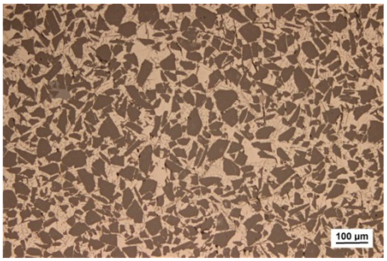
Figure 1. Microstructure of 55 vol.% SiCp/ZL102 composites.
Metals 10 01470 g001
Figure 2. Metallographic structure of the as-cast brazing filler metal.
Metals 10 01470 g002
Figure 3. Foil-like brazing material fabricated by melt-spinning technology.
Metals 10 01470 g003
Figure 4. Schematic diagram of the brazing joint.
Metals 10 01470 g004
Figure 5. DSC curve of the brazing filler metal alloy: (a) as-cast brazing filler metal; (b) foil-like brazing filler metal.
Metals 10 01470 g005
Figure 6. Microstructure of the as-cast brazing filler metal.
Metals 10 01470 g006
Figure 7. Microstructure of the foil-like brazing filler metal: (a) microstructure of the free surface; (b) microstructure of the near-roller surface.
Metals 10 01470 g007
Figure 8. X-ray diffraction analysis curve of the foil-like brazing filler metal.
Metals 10 01470 g008
Figure 9. Optical microstructure of joints brazed at different temperatures: (a) 560 °C; (b) 570 °C; (c) 580 °C; (d) 590 °C; (e) 600 °C.
Metals 10 01470 g009
Figure 10. SEM image of a typical region at the interface of the 55 vol.% SiCp/ZL102 composite joint made at 580 °C and corresponding energy dispersive X-ray analysis: (a) SEM image; (be) individual elemental line scanning profile of Al, Mg, Cu, and Si, respectively.
Metals 10 01470 g010
Figure 11. Shear strength of brazed joints at different temperatures.
Metals 10 01470 g011
Figure 12. Scanning fracture morphology and EDS analysis of the joint made using micro-nano brazing filler metal Al-17.0Cu-8.0Mg at a temperature of 580 °C and holding time of 30 min: (a) one side of the fracture; (b) the other side of the fracture.
Metals 10 01470 g012
Figure 13. Shear curve at a temperature of 580 °C and holding time of 30 min.
Metals 10 01470 g013
Table 1. Chemical composition of ZL102 (in wt.%).
ElementSiFeCuMnMgZnTiAl
wt.%10.0–13.00.0–0.7≤0.30≤0.50≤0.10≤0.10≤0.20Balance
Publisher’s Note: MDPI stays neutral with regard to jurisdictional claims in published maps and institutional affiliations.