
Powder Forging of in Axial and Radial Direction Graded Components of TRIP-Matrix-Composite


Abstract
1. Introduction
2. Materials and Methods
3. Results
4. Discussion
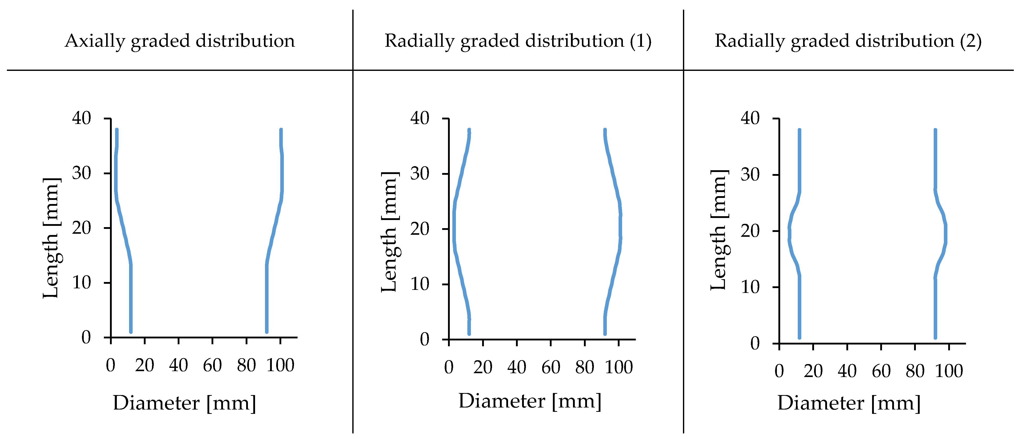
4.1. Bulging Tests
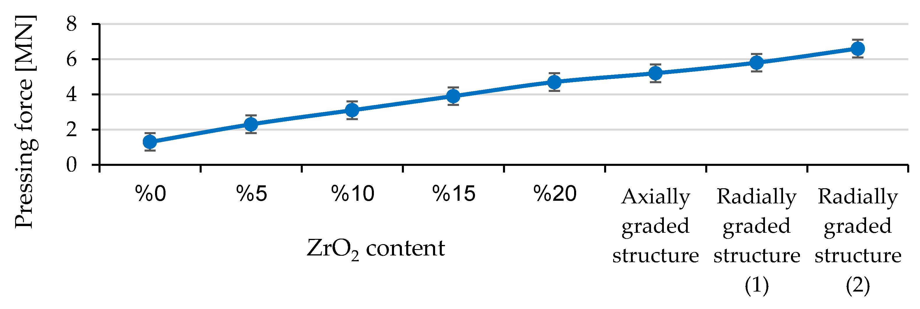
4.2. Compressive Forces
4.3. Relative Density
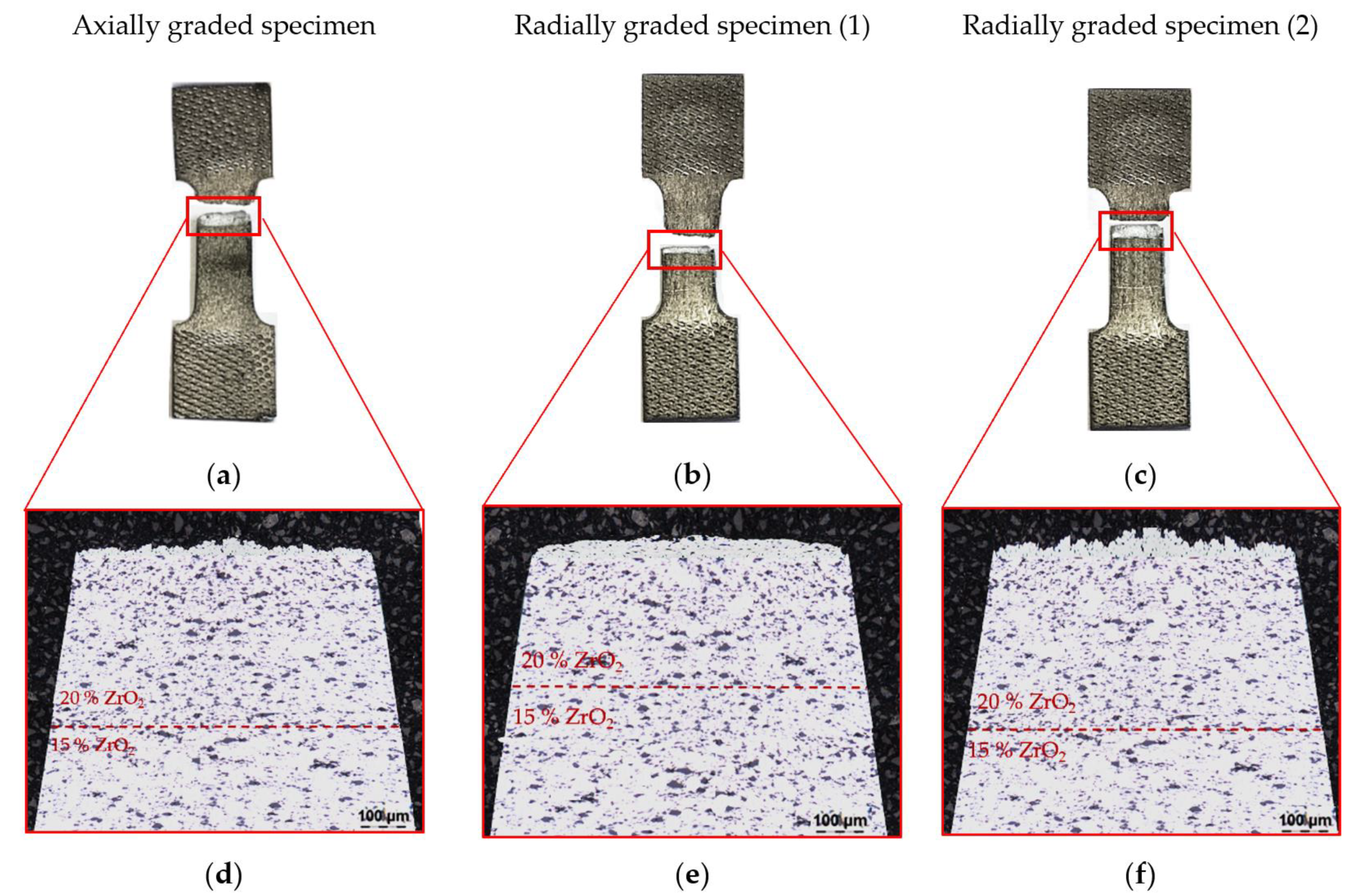
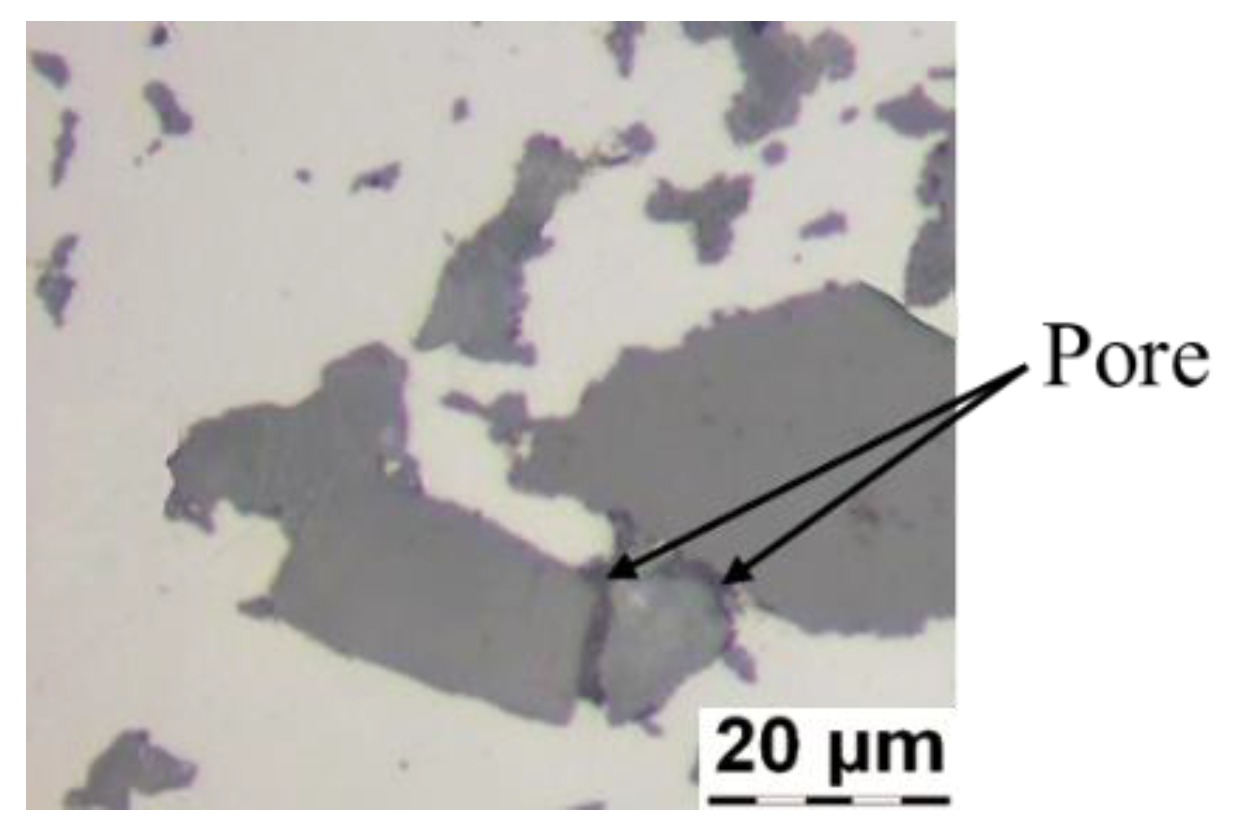
4.4. Light Microscopy Imaging
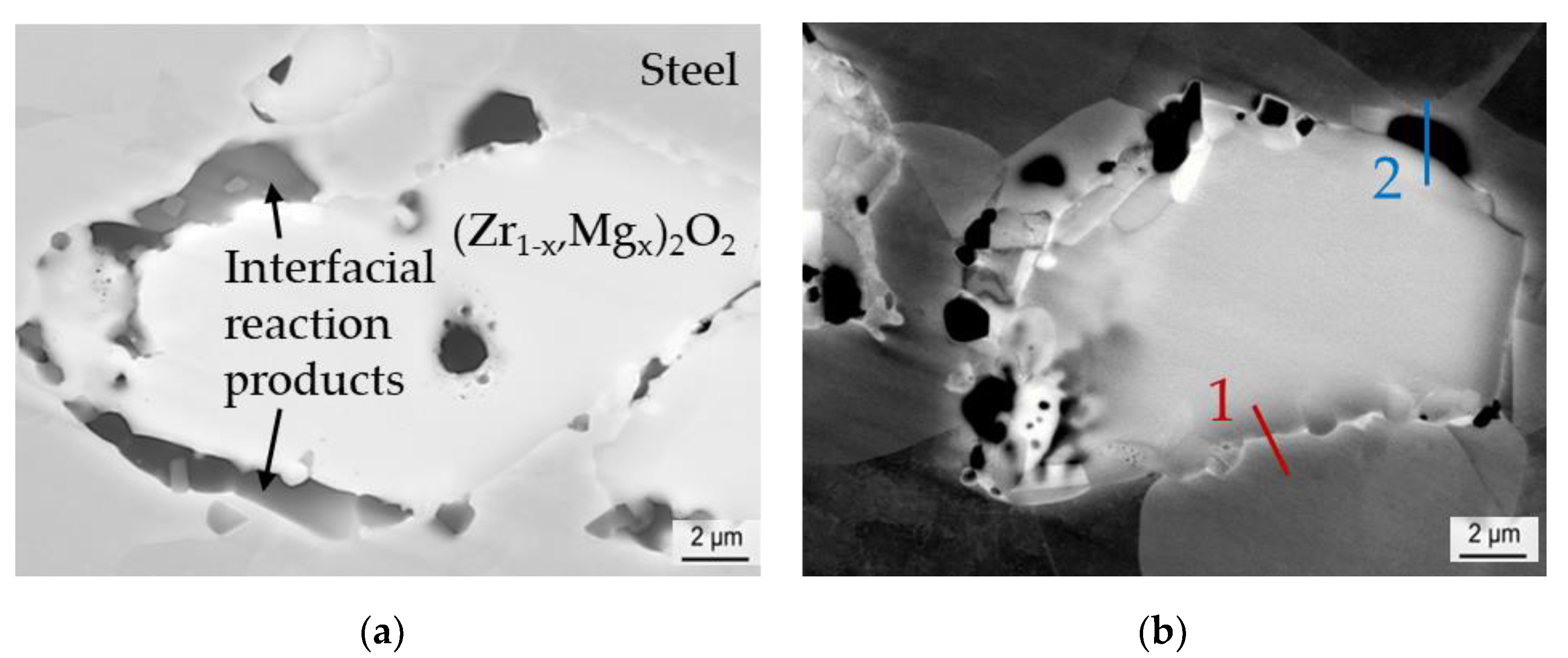
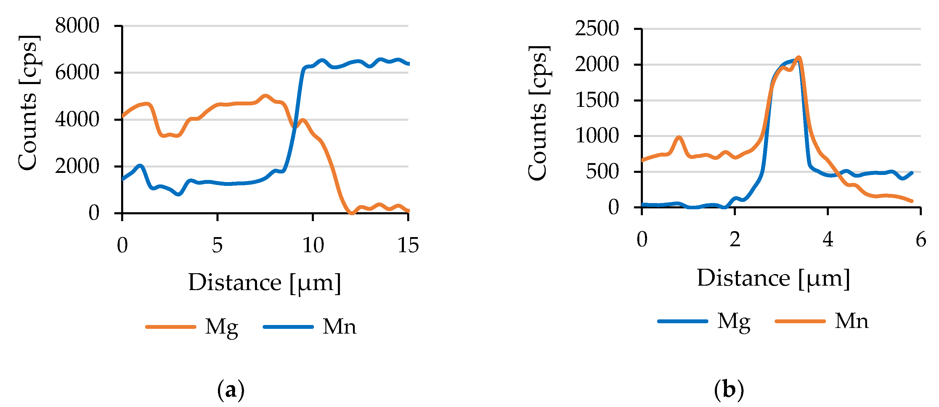
4.5. SEM Imaging
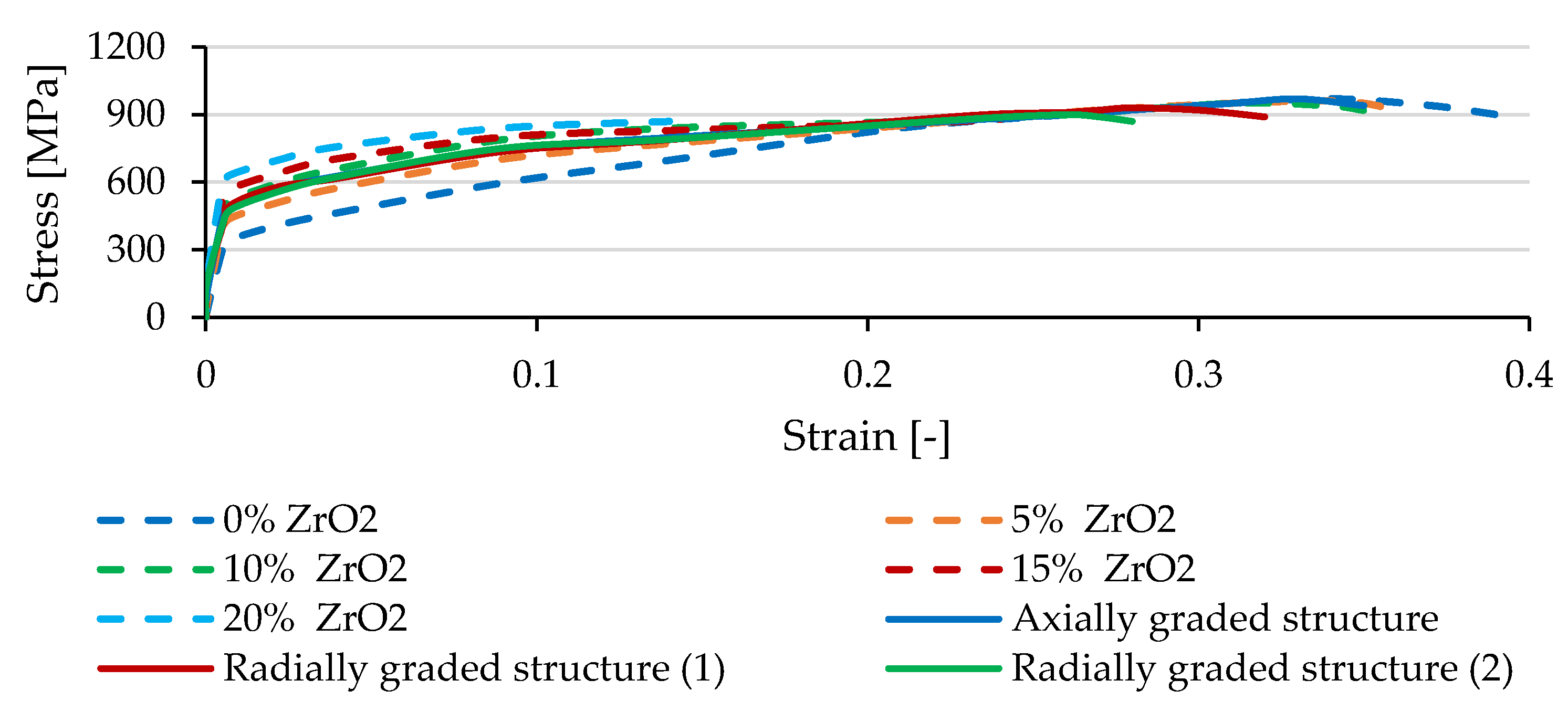
4.6. Tensile Tests
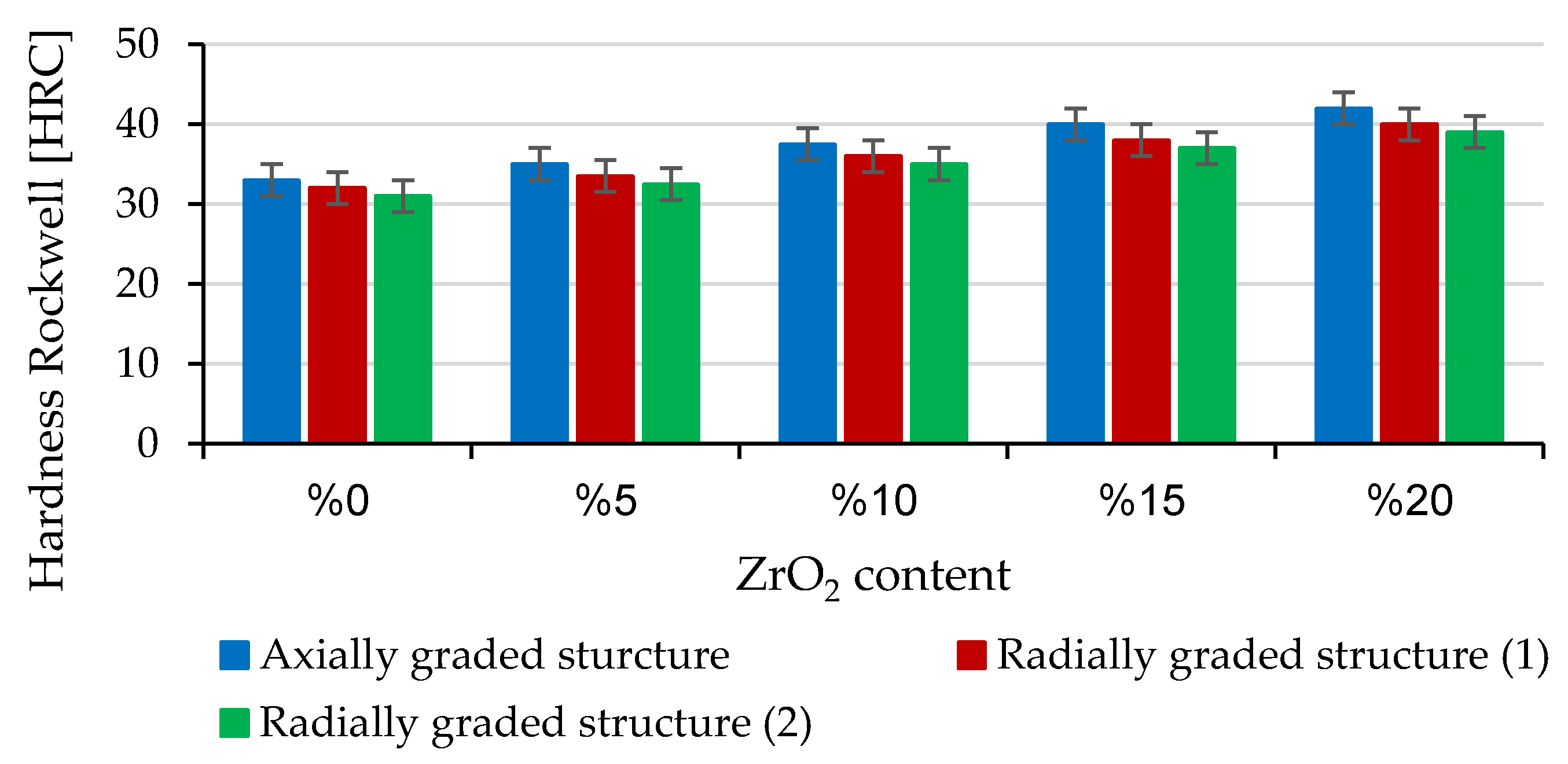
4.7. Hardness Tests
5. Conclusions
- (1)
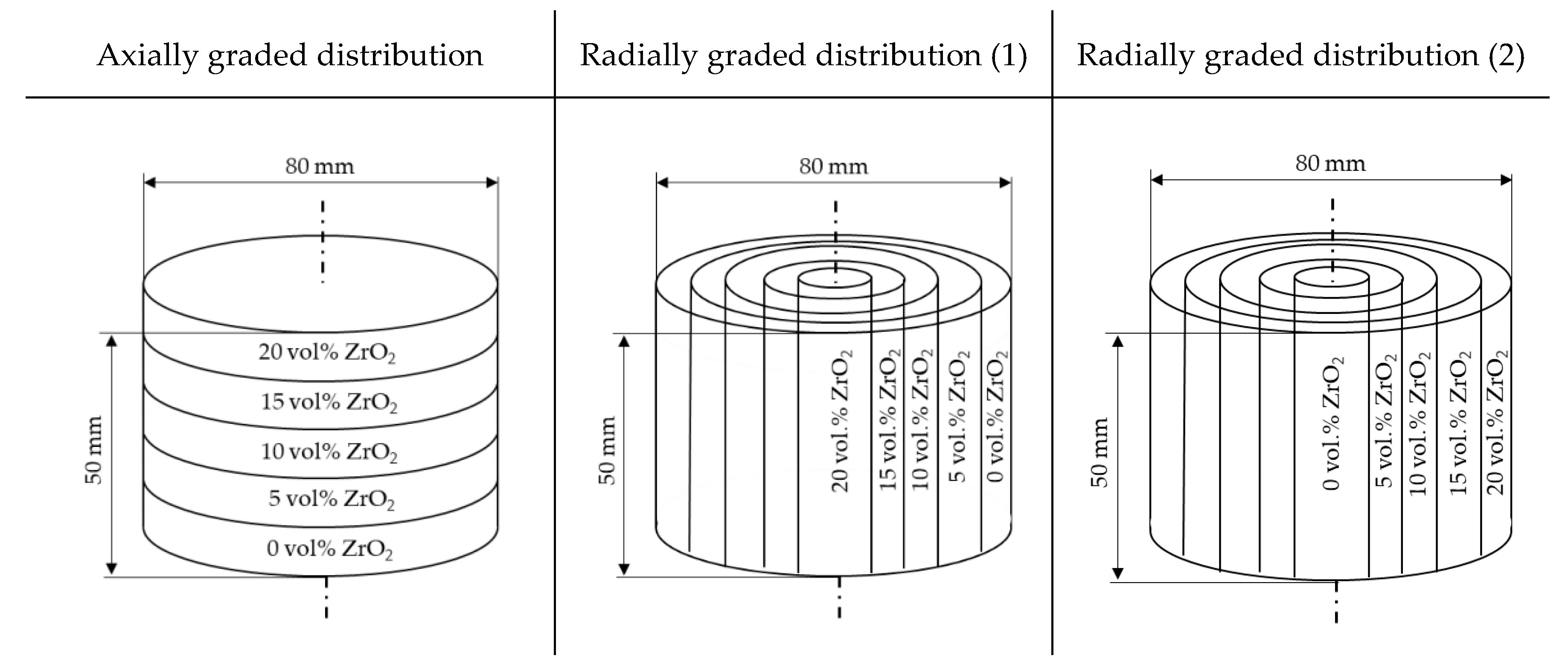
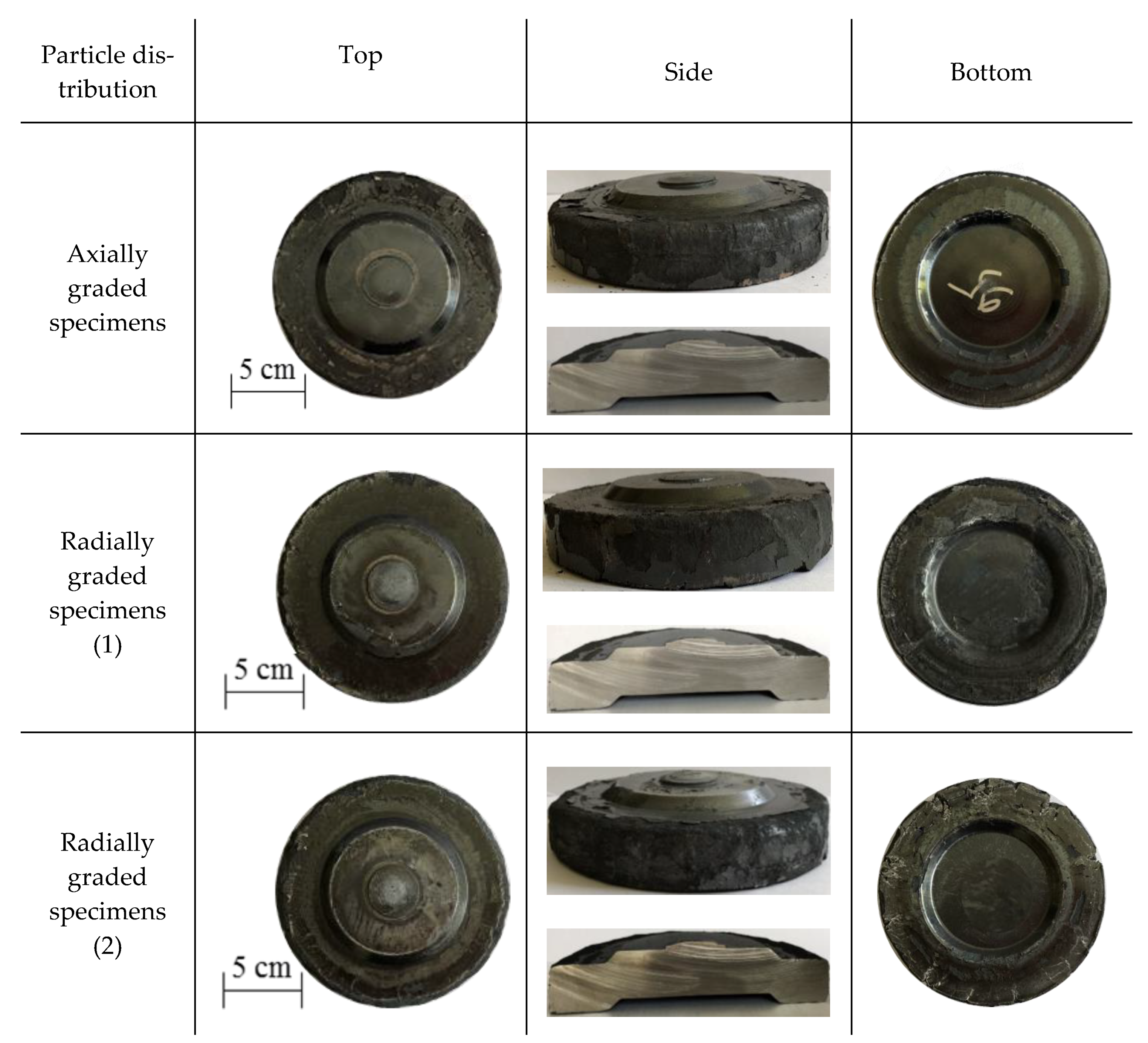
- The powder forging conditions allow compressing specimens with an axially graded particle distribution and at the same time to obtain a local homogeneous particle distribution;
- (2)
- The powder forging conditions do not allow under the same parameters as for axially graded specimens in order to compress radially graded specimens and at the same time to obtain a local homogeneous particle distribution;
- (3)
- With regard to the bonding of the reinforcing particles, the powder forging conditions allow in all cases their complete incorporation within the TRIP steel matrix, resulting in a solid compound;
- (4)
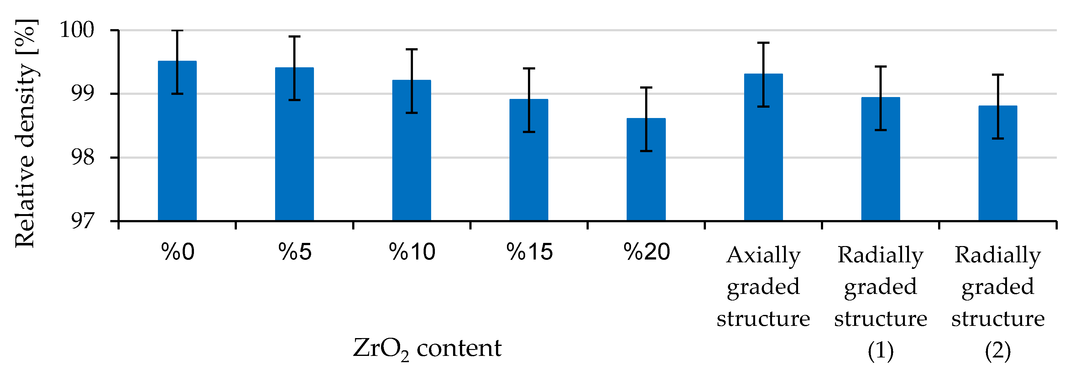
- The configuration of the radially graded specimen structure has a strong influence on its macroscopical density and mechanical properties;
- (5)
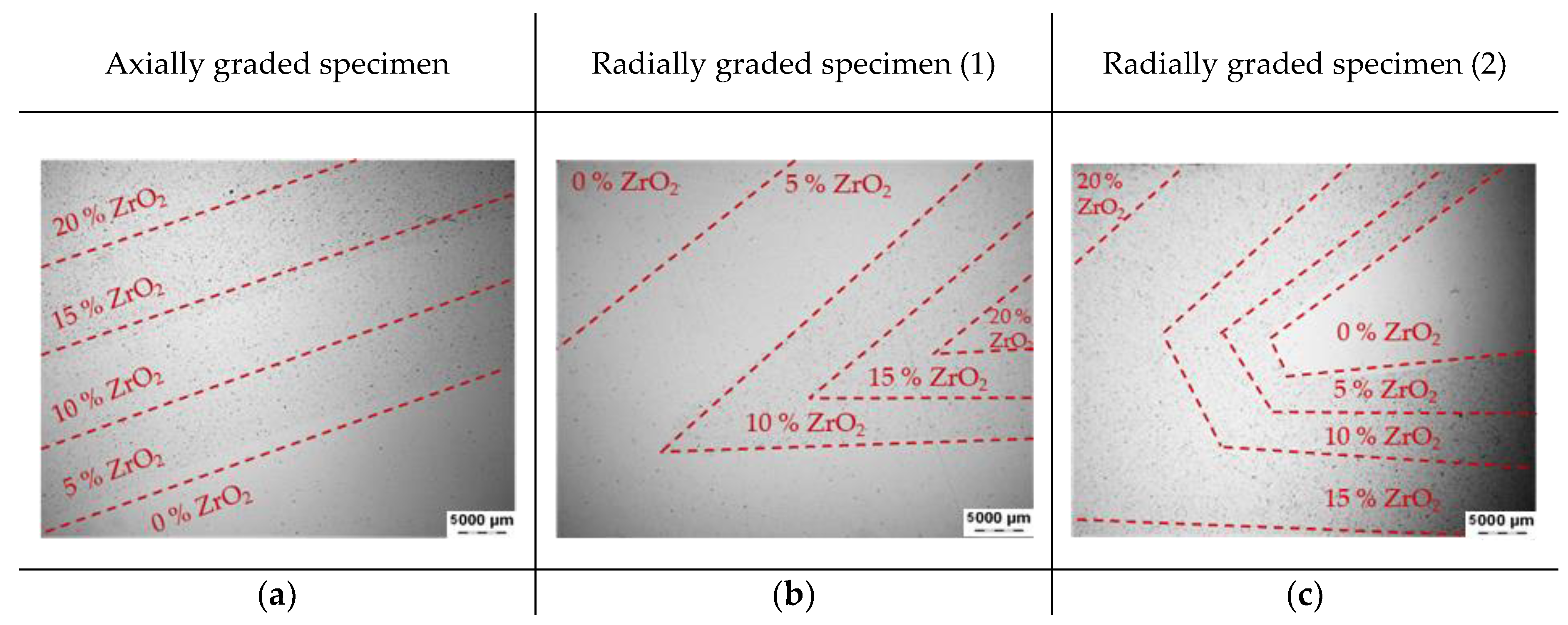
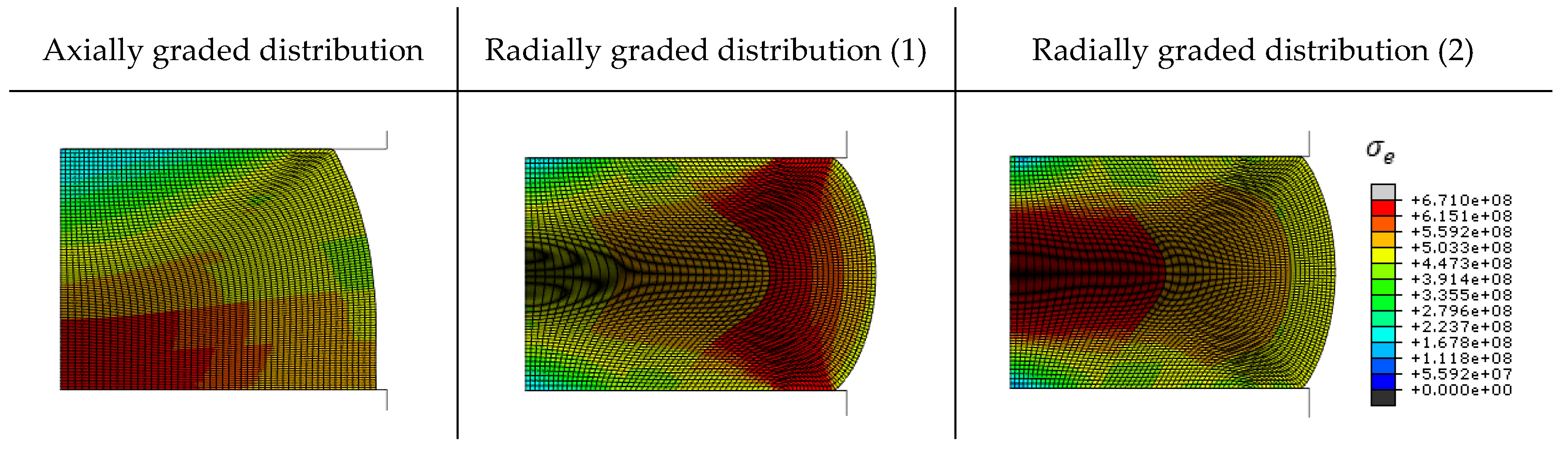
- The layers with high ceramic particle content were the critical regions of the graded specimens, leading to the crack initiation and propagation there;
- (6)
- The achieved yield strength shows a dependence on the configuration of the radially graded specimen structure;
- (7)
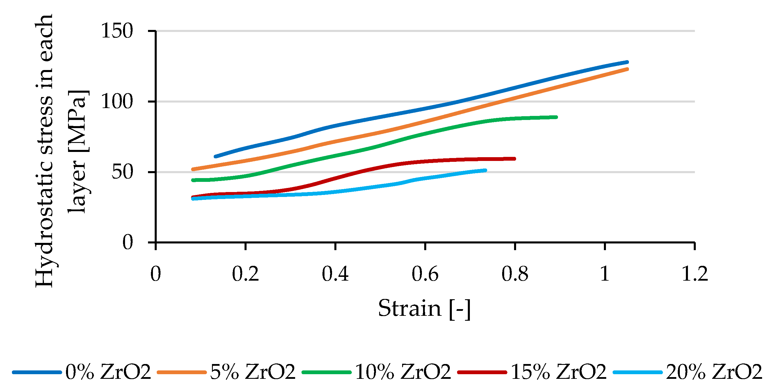
- The reinforcing particles generate a stress field, which increases with the increasing content of reinforcing particles, in the matrix, which is opposed to the hydrostatic stress field and inhibits forming and compaction;
- (8)
- The bulging model of axially graded specimens described and predicted in [35] was experimentally validated. The results showed a very good agreement with experimentally determined values;
- (9)
- The TRIP effect in the steel matrix as well as the tetragonal structure of ZrO2 remained even after powder forging and forming. Thus, no premature phase transformations that negatively influence the properties of the components occur during the manufacturing process.
Author Contributions
Funding
Data Availability Statement
Acknowledgments
Conflicts of Interest
References
- Birman, V.; Byrd, L.W. Modeling and analysis of functionally graded materials and structures. Appl. Mech. Rev. 2007, 60, 195–216. [Google Scholar]
- Pourmajidian, M.; Akhlaghi, F. Fabrication and characterization of functionally graded Al/SiCp composites produced by remelting and sedimentation process. J. Mater. Eng. Perform. 2013, 23, 444–450. [Google Scholar] [CrossRef]
- Liew, K.M.; Lei, Z.X.; Zhang, L.W. Mechanical analysis of functionally graded carbon nanotube reinforced composites: A review. Compos. Struct. 2015, 120, 90–97. [Google Scholar] [CrossRef]
- Raßbach, S. Grundlegende Untersuchungen zum Umformverhalten von Gradientenwerkstof-fen unter Anwendung von Druckformverfahren. Ph.D. Thesis, TU Bergakademie Freiberg, Freiberg, Germany, 2002. [Google Scholar]
- Kolaska, H. Fortschritte bei der Formgebung in Pulvermetallurgie und Keramik: Vorträge Anlässlich des Symposiums am 28./29; Verband Deutscher Ingenieure: Düsseldorf, Germany, 1991. [Google Scholar]
- Behrens, B.A.; Vahed, N.; Brand, H. Pulvermetallurgische Herstellung Gradierter Werkzeugwerkstoffe, 1st ed.; Leibniz Universität Hannover: Hannover, Germany, 2013. [Google Scholar]
- Elsner, P. Gradierte Werkstoffeigenschaften: Eine Herausforderung für die Fertigungs-technik. Futur 2005, 14, 16–18. [Google Scholar]
- Zeming, H.; Ma, J.; Tan, G.E.B. Fabrication and characteristics of alumina—Iron functionally graded materials. J. Alloys Compd. 2009, 468, 815–818. [Google Scholar]
- Li, J.; Sun, W.; Ao, W.; Gu, K.; Xiao, P. Al2O3—FeCrAl composites and functionally graded materials fabricated by reactive hot pressing. Compos. Part A Appl. Sci. Manuf. 2007, 38, 615–620. [Google Scholar] [CrossRef]
- Sahu, M.; Dargar, M.K.; Bartaria, V.N. The effect of hot forging and heat treatment on tribologocal properties of Al alloy & nano composites. Int. J. Sci. Eng. Technol. 2013, 76, 649–661. [Google Scholar]
- Schiller, W. Neue Konzepte zum Kalibrieren von Sinterbauteilen. Diploma Thesis, Montanuniversität Leoben, Leoben, Austria, 2010. [Google Scholar]
- Exner, H.E.; Danninger, H. Handbook of Inorganic Chemistry, Metallurgy of Iron: Powder Metallurgy of Steel, 10th ed.; Springer: Berlin/Heidelberg, Germany, 1992. [Google Scholar]
- Kuhn, H.A.; Lynn, B. Powder Forging. Powder Metallurgy; U.S. Department of Energy Office of Scientific and Technical Information: Oak Ridge, TN, USA, 1990; pp. 3–19.
- Vossen, K. Pulverschmieden von gerad- und Schrägverzahnten Zylinderrädern. Ph.D. Thesis, RWTH Aachen, Aachen, Germany, 1987. [Google Scholar]
- Zapf, G. Handbuch der Fertigungstechnik: Urformen; Carl Hanser Verlag: Munich, Germany, 1981. [Google Scholar]
- Gillia, O.; Caillens, B. Fabrication of a material with composition gradient for metal/ceramic assembly. Powder Technol. 2011, 208, 355–366. [Google Scholar] [CrossRef]
- Miracle, D. Metal matrix composites—From science to technological significance. Compos. Sci. Technol. 2005, 65, 2526–2540. [Google Scholar] [CrossRef]
- Kaczmar, J.; Pietrzak, K.; Włosiński, W. The production and application of metal matrix composite materials. J. Mater. Process. Technol. 2000, 106, 58–67. [Google Scholar] [CrossRef]
- Chawla, N.; Shen, Y.-L. Mechanical behavior of particle reinforced metal matrix composites. Adv. Eng. Mater. 2001, 3, 357–370. [Google Scholar] [CrossRef]
- Weigelt, C.; Jahn, E.; Berek, H.; Aneziris, C.G.; Eckner, R.; Krüger, L. Joining of Zirconia reinforced metal-matrix composites by a ceramics-derived technology. Adv. Eng. Mater. 2015, 17, 1357–1364. [Google Scholar] [CrossRef]
- Ehinger, D.; Krüger, L.; Martin, U.; Weigelt, C.; Aneziris, C.G. Buckling and crush resistance of high-density TRIP-steel and TRIP-matrix composite honeycombs to out-of-plane compressive load. Int. J. Solids Struct. 2015, 66, 207–217. [Google Scholar] [CrossRef]
- Glage, A.; Weigelt, C.; Räthel, J.; Biermann, H. Fatigue behaviour of hot pressed austenitic TWIP steel and TWIP steel/Mg-PSZ composite materials. Int. J. Fatigue 2014, 65, 9–17. [Google Scholar] [CrossRef]
- Biermann, H.; Martin, U.; Aneziris, C.G.; Kolbe, A.; Müller, A.; Schärfl, W.; Herrmann, M. Microstructure and compression strength of novel TRIP-Steel/Mg-PSZ composites. Adv. Eng. Mater. 2009, 11, 1000–1006. [Google Scholar] [CrossRef]
- Tamura, I. Deformation-induced martensitic transformation and transformation-induced plasticity in steels. Met. Sci. 1982, 16, 245–253. [Google Scholar] [CrossRef]
- Zackay, V.F.; Parker, E.R.; Fahr, D.; Busch, R. The enhancement of ductility in high-strength steels. ASM Trans. Quart 1967, 60, 252–259. [Google Scholar]
- Weigelt, C.; Aneziris, C.; Ehinger, D.; Eckner, R.; Krüger, L.; Ullrich, C.; Rafaja, D. Effect of zirconia and aluminium titanate on the mechanical properties of transformation-induced plasticity-matrix composite materials. J. Compos. Mater. 2015, 49, 3567–3579. [Google Scholar] [CrossRef]
- Yingkui, G.U.O.; Yu, Z.H.O.U.; Dongbo, L.I.; Xiaoming, D.U.A.N.; Tingquan, L.E.I. Microstructure and performance of 2Y-PSZ/TRIP steel composites. J. Mater. Sci. Technol. 2003, 19, 137–140. [Google Scholar]
- Yu, Z.; Yingkui, G.; Dongbo, L.; Xiaoming, D. Effects of load mode on mechanical properties of ZrO2 (2Y)/TRIP steel composites. Trans. Nonferr. Met. Soc. China 2003, 5, 1086–1091. [Google Scholar]
- Manolache, V.; Schlieper, G.; Huppmann, W.J. Moderne Formgebungsverfahren: Pulvermetallurgie: Pulvermetallurgische Herstellung von Schichtverbunden; Keramik: Berlin, Germany, 1985; pp. 213–220. [Google Scholar]
- Behrens, B.-A.; Uhe, J.; Wester, H.; Matthias, T.; Büdenbender, C. FE-based layer design of deposition-welded semi-finished parts for the production of hybrid bevel gear. Procedia Manuf. 2020, 47, 309–314. [Google Scholar] [CrossRef]
- Behrens, B.-A.; Bohr, D. Manufacturing of functionally graded metal matrix composite materials by segregation. Int. J. Mater. Res. 2018, 109, 373–380. [Google Scholar] [CrossRef]
- Baumann, A. Pulverspritzgießen von Metall-Keramik-Verbunden. Diploma Thesis, TU Freiberg, Freiberg, Germany, 2010. [Google Scholar]
- Kirschner, M.; Guk, S. Beitrag zur Bewertung des Verdichtungsgrades Mittels Visioplatsizität; Werkstoffwoche: Dresden, Germany, 2019. [Google Scholar]
- Kirschner, M.; Eckner, R.; Guk, S.; Krüger, L.; Kawalla, R.; Prahl, U. Deformation behavior of particle reinforced TRIP Steel/MgPSZ composite at hot working temperatures. Steel Res. Int. 2019, 90, 1800334. [Google Scholar] [CrossRef]
- Kirschner, M.; Guk, S.; Kawalla, R.; Prahl, U. Further development of process maps for TRIP matrix composites during powder forging. Mater. Sci. Forum 2019, 949, 15–23. [Google Scholar] [CrossRef]
- Kirschner, M.; Guk, S.; Kawalla, R.; Prahl, U. Austenitic TRIP/TWIP Steels and Steel-Zirconia Composites: Powder Forging of Pre-sintered TRIP-Matrix Composites; Springer Series in Materials Science 298; Biermann, H., Aneziris, C.G., Eds.; Springer: Berlin/Heidelberg, Germany, 2020; Volume 1. [Google Scholar]
- Narayanasamy, R.; Ramesh, T.; Pandey, K.S. Some aspects of workability studies in cold forging of pure aluminium powder metallurgy compacts. Mater. Sci. Technol. 2005, 21, 912–916. [Google Scholar] [CrossRef]
- Guk, S.; Pranke, K.; Müller, W. Flow curve modelling of an Mg-PSZ reinforced TRIP-matrix-composite. ISIJ Int. 2014, 54, 2416–2420. [Google Scholar] [CrossRef]
- Kirschner, M.; Martin, S.; Guk, S.; Prahl, U.; Kawalla, R. Forming complex graded and homogeneous components by joining simple presintered parts of TRIP-matrix composite through powder forging. Metals 2020, 10, 543. [Google Scholar] [CrossRef]
- Martin, S.; Berek, H.; Aneziris, C.G.; Martin, U.; Rafaja, D. Pitfalls of local and quantitative phase analysis in partially stabilized zirconia. J. Appl. Crystallogr. 2012, 45, 1136–1144. [Google Scholar] [CrossRef]
- Kirschner, M.; Guk, S.; Prahl, U.; Kawalla, R. Compaction of Powder Composites for Constructions with High Wear Resistance Requirements. In Proceedings of the XVI International Forum of Young Researchers, St. Petersburg, FL, USA, 17–19 June 2020. [Google Scholar]
- Flodin, A.; Andersson, M.; Miedzinski, A. Full density powder metal components through hot isostatic pressing. Met. Powder Rep. 2017, 72, 107–110. [Google Scholar] [CrossRef]
- Gasik, M.; Cherradi, N.; Kawasaki, A. FGM components: PM meets the challenge. Met. Powder Rep. 1996, 12, 28–32. [Google Scholar]
- Rogowski, D. Verfahren zur Herstellung von Preforms für Metal-Matrix-Composites; European Patent Office: Munich, Germany, 2009. [Google Scholar]
- Dahl, J.R. Powder forged or C-70 steel? Now the MPIF strikes back. Met. Powder Rep. 2005, 60, 14–17. [Google Scholar]
- Thomson, P. Densification of sintered metal compacts by cold deformation. J. Mech. Work. Technol. 1986, 13, 219–227. [Google Scholar] [CrossRef]
- Schaub, W.; Stilz, M.; Geiger, R. Umformtechnik—Handbuch für Industrie und Wissenschaft: Band 4: Sonderverfahren, Prozeßsimulation, Werkzeugtechnik, Produktion, 2nd ed.; Springer: Berlin, Germany, 1993. [Google Scholar]
- Pranke, K.; Guk, S. Material flow in Mg-PSZ particle reinforced TRIP-matrix-composites due to hot-rolling. Key Eng. Mater. 2016, 684, 97–103. [Google Scholar] [CrossRef]
- Berek, H.; Yanina, A.; Weigelt, C.; Aneziris, C.G. Determination of the phase distribution in sintered TRIP-matrix / Mg-PSZ composites using EBSD. Steel Res. Int. 2011, 82, 1094–1100. [Google Scholar] [CrossRef]
- Pavlyuchkov, D.; Dilner, D.; Savinykh, G.; Fabrichnaya, O. Phase equilibria in the ZrO2—MgO—MnO x system. J. Am. Ceram. Soc. 2016, 99, 3136–3145. [Google Scholar] [CrossRef]
- Martin, S.; Decker, S.; Krüger, L.; Martin, U.; Rafaja, D. Microstructure changes in TRIP Steel/Mg-PSZ composites induced by low compressive deformation. Adv. Eng. Mater. 2013, 15, 600–608. [Google Scholar] [CrossRef]
- Bokuchava, G.D.; Gorshkova, Y.; Papushkin, I.V.; Guk, S.V.; Kawalla, R. Investigation of plastically deformed TRIP-composites by neutron diffraction and small-angle neutron scattering methods. J. Surf. Investig. X-ray Synchrotron Neutron Tech. 2018, 12, 227–232. [Google Scholar] [CrossRef]
- Guk, S.; Milisova, D.; Pranke, K. Influence of deformation conditions on the microstructure and formability of sintered Mg-PSZ reinforced TRIP-matrix-composites. Key Eng. Mater. 2016, 684, 86–96. [Google Scholar] [CrossRef]
- Li, C.; Ellyin, F. Short crack growth behavior in a particulate-reinforced aluminum alloy composite. Met. Mater. Trans. A 1995, 26, 3177–3182. [Google Scholar] [CrossRef]
- Hochreiter, E.; Panzenböck, M.; Jeglitsch, F. Fatigue properties of particle-reinforced metal-matrix composites. Int. J. Fatigue 1993, 15, 493–499. [Google Scholar] [CrossRef]
- Seo, B.H.; Kim, J.H.; Park, J.B.; Jung, G.D. Crack propagation characteristics of particulate reinforced composites using digital image correlation. Mater. Werkst. 2015, 46, 387–393. [Google Scholar] [CrossRef]
- Shang, J.K.; Ritchie, R. On the particle-size dependence of fatigue-crack propagation thresholds in SiC-particulate-reinforced aluminum-alloy composites: Role of crack closure and crack trapping. Acta Met. 1989, 37, 2267–2278. [Google Scholar] [CrossRef]
- Wang, Z.; Zhang, R.J. Microscopic characteristics of fatigue crack propagation in aluminum alloy based particulate reinforced metal matrix composites. Acta Met. Mater. 1994, 42, 1433–1445. [Google Scholar] [CrossRef]
- Vahed, N. Einfluss des Materialflusses auf die Verdichtung beim Sinterschmieden; Umformtechnik: Verlag Meisenbach GmbH: Bamberg, Germany, 2014; pp. 2–11. [Google Scholar]


| TRIP Steel | Fe | C | Cr | Ni | Mn | Si | N | Al | S | Mo | Ti |
|---|---|---|---|---|---|---|---|---|---|---|---|
| (wt%) | bal. | 0.03 | 16.3 | 6.6 | 7.2 | 1.0 | 0.09 | 0.04 | <0.01 | <0.01 | <0.01 |
| Mg-PSZ | ZrO2 | HfO2 | MgO | SiO2 | Al2O3 | CaO | TiO2 | Y2O3 | |||
| (wt%) | bal. | 1.85 | 3.25 | 0.1 | 1.58 | 0.06 | 0.13 | 0.13 |
Publisher’s Note: MDPI stays neutral with regard to jurisdictional claims in published maps and institutional affiliations. |
© 2021 by the authors. Licensee MDPI, Basel, Switzerland. This article is an open access article distributed under the terms and conditions of the Creative Commons Attribution (CC BY) license (http://creativecommons.org/licenses/by/4.0/).
Share and Cite
Kirschner, M.; Guk, S.; Kawalla, R.; Prahl, U. Powder Forging of in Axial and Radial Direction Graded Components of TRIP-Matrix-Composite. Metals 2021, 11, 378. https://doi.org/10.3390/met11030378
Kirschner M, Guk S, Kawalla R, Prahl U. Powder Forging of in Axial and Radial Direction Graded Components of TRIP-Matrix-Composite. Metals. 2021; 11(3):378. https://doi.org/10.3390/met11030378
Chicago/Turabian StyleKirschner, Markus, Sergey Guk, Rudolf Kawalla, and Ulrich Prahl. 2021. "Powder Forging of in Axial and Radial Direction Graded Components of TRIP-Matrix-Composite" Metals 11, no. 3: 378. https://doi.org/10.3390/met11030378
APA StyleKirschner, M., Guk, S., Kawalla, R., & Prahl, U. (2021). Powder Forging of in Axial and Radial Direction Graded Components of TRIP-Matrix-Composite. Metals, 11(3), 378. https://doi.org/10.3390/met11030378