1. Introduction
Precipitation is a common phenomenon in alloys and can be used to influence the mechanical properties, e.g., of steels via precipitation hardening. As for many other phase transformations, the driving forces for precipitate formation are of thermodynamic origin, which means that an alloy can reduce its relevant energy (e.g., the Gibbs energy) by phase separation. Often, precipitation is also influenced by kinetic effects, which can, e.g., lead to precipitate-free zones near grain boundaries, which act as sinks for impurities and can therefore generate a corridor of reduced supersaturation around a grain boundary, where consequently, the thermodynamic driving force for precipitate formation is reduced [
1]. This interplay of thermodynamic and kinetic aspects is prominent in bainitic steels, where carbide precipitation can occur both in the the austenitic matrix and bainitic ferrite with a low solubility limit for carbon. Bainite is a highly interesting microstructure in steels for many applications due to the characteristic mechanical properties, which still lacks a full understanding of the underlying multi-scale microstructure [
2]. In particular, the debate on the nature of the transformation, whether it is diffusion controlled or displacive, is ongoing; see, e.g., [
3] for a recent review. Depending on the quenching conditions and the resulting front propagation velocity between austenite and ferrite, which is in competition with carbon diffusion, carbides appear preferentially on one (upper bainite) or the both sides (lower bainite) of this moving interface, with an influence on the mechanical properties of the steel; see
Figure 1.
Therefore, obviously, the formation of carbide precipitates plays a crucial role in bainitic transformations and requires a deeper understanding.
Next to the interaction of the bulk thermodynamic and kinetic effects, the proximity of the precipitates to phase boundaries is a characteristic feature of many phase transition phenomena, which shall be elucidated in this paper. If we consider a multi-phase setup (like austenite, ferrite, carbide in bainite) from a purely bulk thermodynamic perspective, the spatial arrangement of the phases should not play a role, as long as no long-range interactions are considered. A new complexity appears if mechanical effects are considered, which inevitably play a decisive role in many solid-state transformations, which bring surprising new features even if the different phases are not even in direct contact with each other. Mechanical effects are a striking element during bainitic transformations and are widely discussed in the literature, e.g., in the context of a surface relief [
4]. Whereas a complete understanding of the bainite morphologies will require a detailed understanding of the complex interplay of thermodynamic, kinetic and elastic effects, we will focus here on the equilibrium aspects alone to separate them intentionally from the kinetic effects. Nevertheless, one has to keep in mind that thermodynamic effects serve as driving forces for kinetic effects, and therefore influence them.
The key idea of the following discussion is the assumption that a precipitate introduces a mechanical deformation both inside the precipitate and in the surrounding matrix. This is accompanied by a modification of the bulk elastic energy, which therefore influences the thermodynamics of phase coexistence. Whereas this effect is well understood from a thermodynamic perspective on a bulk level (see, e.g., [
5,
6,
7,
8,
9,
10,
11]), additional effects can arise if a precipitate forms near surfaces or interfaces, which is a typical situation in bainite. It is worthwhile to note that the interface proximity can increase or decrease the elastic energy and therefore can make precipitation less or more likely in these regions. This effect is expected to play a role whenever precipitates show a lattice mismatch with the matrix, and the effect will play the largest effect for coherent interfaces between them. We will discuss here two limiting cases that we have elaborated during the past years for phase separation near free and confined surfaces [
12,
13] and shear-coupled grain boundaries [
14] and show what may happen near interfaces between different phases as a consequence of coherent-incoherent transitions. The aforementioned two limiting cases also lead to a distinction of what we call here “reactive” and “passive” surfaces and interfaces, which influence the range of interaction between interfaces and precipitates in the spirit of a strong thermo-chemo-mechanical coupling. Finally, we discuss how the interface interaction aspect can be covered within scale bridging descriptions, which are of interest, e.g., for the prediction of the microstructure evolution of bainite with its intrinsic multiscale character.
The article is structured as follows: In
Section 2, we first revisit our recent work on the thermodynamics of precipitates near surfaces and interfaces as a basis for scale bridging considerations and generalization to precipitates near phase boundaries. We focus here on the role of elastic effects, which introduce an effective interaction with the aforementioned types of interfaces, with different interaction ranges. In
Section 3, we investigate a different stress relaxation effect at grain boundaries, which is due to shear-coupled motion. It turns out that it can similarly lead to a modification of the precipitation conditions near a grain boundary. These effects are typically difficult to incorporate into mesoscopic descriptions of microstructure evolution, which are implicitly assuming coherent interfaces. To overcome this restriction, we develop an effective description using an elastic softening of a grain boundary layer in
Section 4, which can be tuned to reproduce the shear-coupled motion results. With this, we also show the way to generalize the modeling approach to multi-phase situations and the consideration of other near interface stress relaxation mechanisms as a coherent-incoherent transition in the concluding
Section 5.
2. Precipitation Near Free Surfaces and Rigid Interfaces
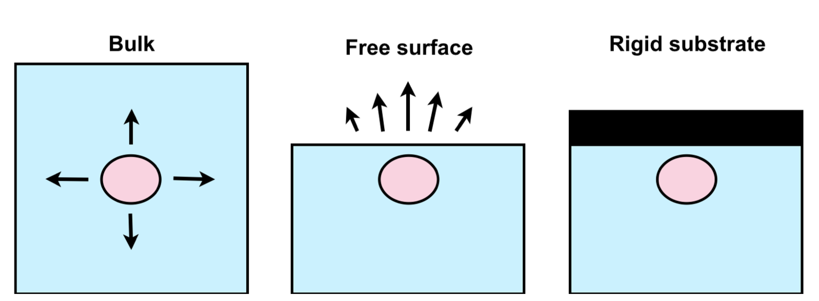
We start with a discussion on precipitation near free surfaces, as illustrated in
Figure 2.
The basic idea is that a nucleus with a mismatching lattice constant with its environment will exert elastic stresses, and therefore raise the elastic energy of the system. This energy contribution makes phase separation energetically less favorable, as described already by Cahn a long time ago [
5,
6]. We note that for a precipitate with a different lattice constant than the matrix phase, we expect elastic deformations both in the matrix and the precipitate. This effect is strongest for the case of a coherent interface between them, which means that the elastic displacement field is continuous at the interface. For the simplest case of fully isotropic materials and a vanishing contrast in elastic constants between the two phases, the shape and location of the precipitate are not relevant from an elastic point of view, as the energy only depends on the volume fraction of the precipitate according to the Bitter–Crum theorem [
15]. We note that this statement holds as long as the precipitate is surrounded by an infinitely large matrix phase (or for a periodic array of precipitates). In this case, the equilibrium shape of a precipitate is determined by the minimization of interfacial energy, and hence spherical for isotropic materials.
The situation changes if a precipitate is closer to a free surface (center panel of
Figure 2), as then, the matrix phase has the ability to relax stresses by normal displacement components at the surface. Therefore, the elastic energy drops if the inclusion gets closer to the interface, and we worked out the resulting interaction in [
12]. Especially, the case of a spherical precipitate close to a planar free surface can be expressed in closed analytical form and exhibits an elastic interaction, which decays as a power law according to
, where
d is the distance between the precipitate and the surface. The relaxation of the elastic energy is expressed through a dimensionless quantity:
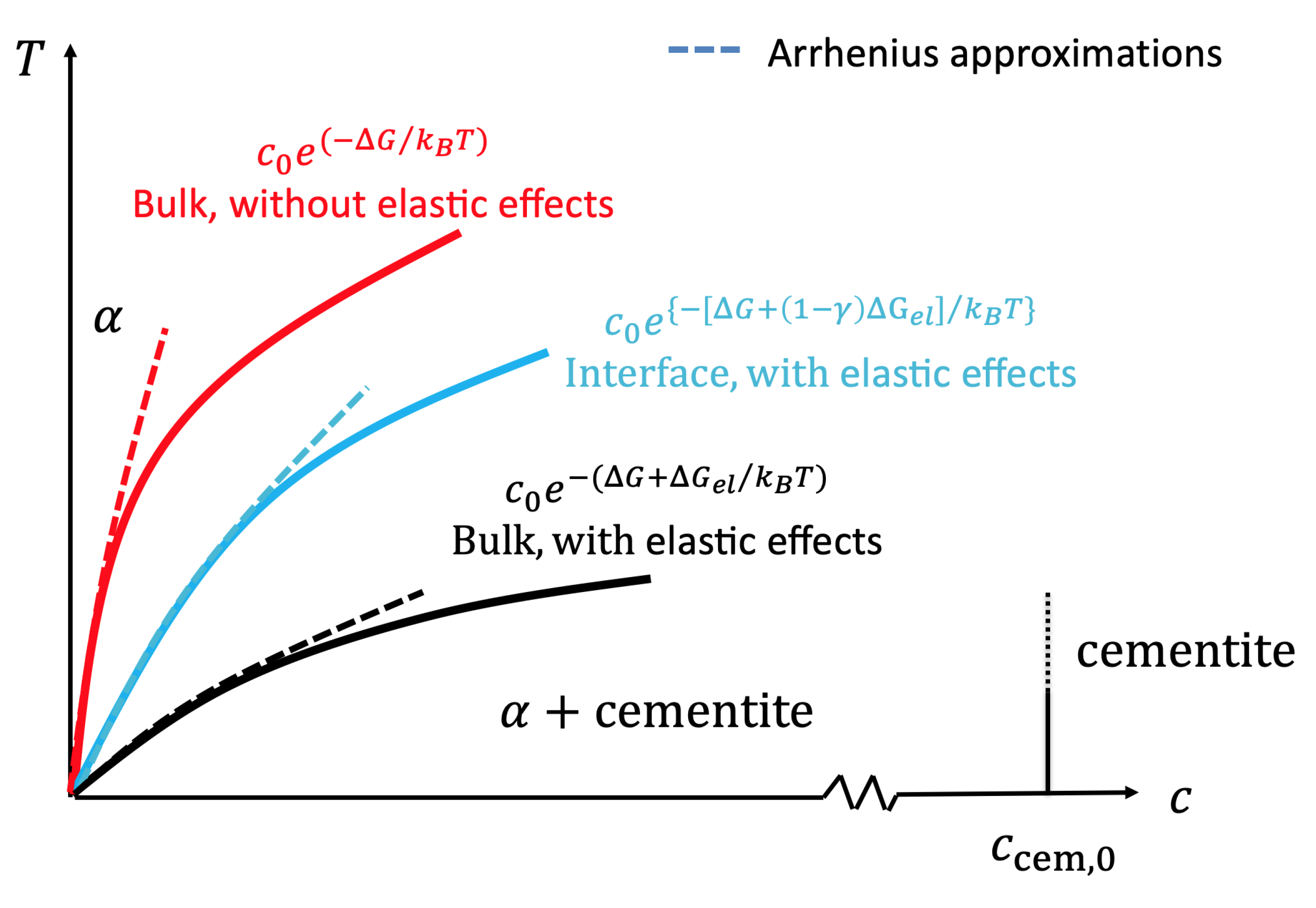
as the ratio of the system’s elastic energy for the precipitate being at a finite distance to a surface compared to the bulk case. Then, for a binary phase diagram with zero solubility at absolute zero, the stress-free solubility limit follows asymptotically for low temperatures an Arrhenius behavior:
with the formation enthalpy difference
. This is the case, e.g., for the carbon solubility in the ferritic
phase of Fe-C (coexistence with cementite); see
Figure 3. Including elastic effects and also near surfaces, the solubility limit becomes:
with the bulk elastic energy barrier:
Here,
E is Young’s modulus,
the Poisson number,
the Vegard coefficient for the lattice expansion through the impurities,
the volume of an impurity-free unit cell, and
the number of atoms within the cell. The concentration in the precipitate phase (e.g., the cementite), which coexists with the low concentration solid solution phase (e.g., the
phase), has a (carbon) concentration of
at absolute zero (see the phase diagram in
Figure 3; we refer to [
12] for a detailed discussion). This expression shows that the solubility limit is increased for bulk elasticity compared to the stress-free case, in agreement with the above discussion, which is reflected by the negative sign of
.
At first glance, the negative sign in Equation (
4) may seem surprising, as the elastic energies are positive. However, one has to keep in mind that the formation energy
is the difference between the energy of the solid solution phase (sign +) and the phase separated state (sign −). Phase separation increases the elastic energy due to coherency strains and therefore increases the second contribution. Consequently, the additional elastic energy contribution appears with a negative sign in Equation (
4).
A key element is the elastic energy rescaling factor
, which has the value
for a precipitate in the bulk, but can take different values near interfaces and surfaces. According to the definition
, it quantifies the relaxation or increase of the elastic energy for a precipitate near an interface compared to a bulk situation. If a precipitate gets closer to a free surface, we get
, and consequently, the elastic term is reduced and the solubility limit decreased. As a result, the coherent solubility limit near a free surface is in between the stress-free and the bulk elastic case and depends on the nucleus-surface distance. The conceptual resulting modification of the phase diagram is sketched in
Figure 3.
The right panel of
Figure 2 illustrates a case where the elastic energy of a two phase system with a precipitate near a surface even increases the elastic energy compared to a bulk situation, and therefore,
. This is due to the suppressed elastic relaxation by the coherency constraint induced by a stiff substrate. Consequently, the solubility limit of the alloying element (e.g., carbon) is effectively increased compared to the bulk elastic case.
We demonstrated that these predictions are in agreement with the Cahn–Hilliard simulations, which include elastic effects [
12]. There, the concentration field (e.g., of carbon) is used to discriminate between the mother phase (low carbon concentration) and the precipitate (high carbon concentration). The elastic displacement field is determined via finite element simulations. The coupling between these two fields is achieved through the lattice expansion, which leads to an eigenstrain proportional to the local concentration according to Vegard’s law. Such a formulation implies a coherent interface between the matrix and precipitate. At the free surface of the sample, we have vanishing shear and normal stresses, which induce the attractive interaction between the free surface and the precipitate. For the details of the model, we refer to [
12]. It is worthwhile to mention that the interaction and the resulting effect on the local thermodynamics are automatically contained in the description and do not require any adoption of the model.
Finally, we mention that in the theoretical analysis above, spherical precipitates are assumed to make the problem analytically accessible. The Cahn–Hilliard simulations show deformations of the precipitate shape when it comes closer to a free surface, which breaks the symmetry of the problem. The determination of the equilibrium shape requires in principle a balancing of elastic and interfacial energy contributions and can lead to a stronger energy reduction than what we have discussed above. Notice that different types of precipitate shapes were considered in [
12] and give an indication for the optimum shape based on the isotropic elastic effects alone. Although the predicted scaling behavior of the effects should be similar also for cases where we deviate from the assumptions of the analytical investigations (in particular, the isotropy and vanishing contrast of the elastic constants of the matrix and precipitate), a more careful analysis is recommended for future investigations of carbide precipitation including the consideration of habit planes and anisotropic interfacial energy.
We note that the effects discussed here are different from potential preferences for precipitate formation directly at interfaces, which can lead to a reduction of interfacial energies. Such interactions have—on mesoscopic scales, where we can consider the interfaces to be sharp—a vanishing interaction range. Furthermore, we do not consider short-range effects on the atomic scale, which are due to different bonding situations and which have frequently been discussed in the literature; see, e.g., [
16].
3. Precipitation Close to Shear-Coupled Grain Boundaries
The preceding investigations raise the question of how the precipitation thermodynamics may be influenced by internal interfaces inside materials, in particular grain boundaries. The central idea of the analysis in the above section is a strong contrast between the elastic properties of adjacent “phases”. The investigated extreme cases were a free surface (contact to a “phase” with vanishing elastic constants) and a stiff substrate (infinitely large elastic constants). A grain boundary is different in this respect as the elastic properties are identical on both sides of this internal interface. For anisotropic materials, the orientation dependence differs, but from the perspective of the simplifications within this article, which include in particular isotropy, the previous description should not lead to an influence of the grain boundary on the local thermodynamics. In other words, a grain boundary is invisible to the precipitate from an elastic perspective, as it coherently connects two identical materials, and we should not expect any elastic interaction between a precipitate and a grain boundary. However, from experimental evidence, it is known that grain boundaries can indeed influence precipitate formation. We already mentioned that this is often due to very localized segregation phenomena and following kinetic depletion in a corridor around a grain boundary. We also point out that a grain boundary itself generates stresses that may interact with a precipitate and therefore change its energetics. However, these stresses originate from individual dislocations at (low angle) grain boundaries and are screened on length scales proportional to the dislocation spacing. For mesoscopic precipitates at distances from a grain boundary that are far beyond the atomic scale, this interaction should be too weak to significantly affect the precipitate formation energetics. Nevertheless, experimental observations hint at an interaction between grain boundaries and precipitates in Al-Sc alloys also at scales beyond the atomic level [
17].
As we detailed in [
14], the situation changes if the grain boundary has the potential for morphological reorganizations, which can lead to a mechanical stress relaxation. In this sense, the grain boundary is not a fixed shape “passive” interface, but “reacts” to the presence of a nearby precipitate. In [
14], we considered the shear-coupled motion of a grain boundary as a potential stress relaxation mechanism, which is related to the amplitude equation and analytical modeling in [
18,
19,
20]. Shear coupling describes the resulting normal motion of a grain boundary, if the two grains are shifted laterally against each other; see
Figure 4.
Mathematically, the displacements in the two grains therefore acquire a tangential shift, which is proportional to the normal motion. In lowest order approximation, this can be expressed as:
where
is the lateral displacement of the upper (lower) grain at the grain boundary,
the coupling parameter, and
the grain boundary contour (
for a planar boundary that is not shifted in the normal direction). Grain boundary migration
generates elastic strain, and therefore raises the elastic energy. At first glance, such a shift seems to be energetically unfavorable and therefore not suitable to serve as the stress relaxation mechanism. However, the situation changes if a nearby precipitate generates its own stress field. We then have formally three contributions to the elastic free energy,
. The energy
describes the elastic energy resulting from the coherency misfit between a precipitate in an infinite matrix; it is always positive and therefore makes the phase separation unfavorable. The energy
results from the shear-coupled motion of the grain boundary and also leads to a positive energy contribution. Finally, the energetic cross term
between the grain boundary and the precipitate can lead to a reduction of the energy, making grain boundary shear coupling favorable as this term can overcompensate the energetic increase resulting from the first two terms. Minimization of the total elastic energy results in [
14]:
where the second term in round brackets reflects the energetic reduction resulting from the precipitate-grain boundary interaction and leads to an energy that is lower than the precipitate energy
in the bulk without the grain boundary. To obtain the above expression, we considered an array of precipitates with lateral distance
W between them and at distance
d from the grain boundary. Geometrically, we used a 2D analysis; hence, the precipitates with radius
R have a cylindrical shape in three dimensions.
For fixed lateral precipitate distance
W, the energy depends exponentially on the distance
from the grain boundary (hidden in the sinh function), as compared to the power law dependence in the previous section. This is the conceptual difference between a “passive” interface with a contrast of elastic constants on the two sides and a “reactive” interface like the shear-coupled grain boundary. Indeed, the above energetic minimization implies an adjustment of the grain boundary shape
, which therefore does not remain straight; see [
14] for a detailed discussion.
Figure 5 shows exemplarily how a grain boundary deforms in equilibrium, if it is approached by a spherical precipitate, and the resulting energy drop is shown in
Figure 5.
Effectively, this leads to an attractive interaction between the precipitate and grain boundary, similar to the case of a precipitate near a free surface.
Similar to the discussion above, we can predict the influence of the energy reduction on the equilibrium phase diagram. As a result, we arrive at an analytical expression for the stress relaxation parameter
, which is given by (see
Figure 6):
As we have
, the energy reduction leads here again to a reduced (carbon) solubility limit near shear-coupled grain boundaries and therefore preferred phase separation there. We estimated that for the Fe-C phase diagram, the equilibrium carbon solubility limit in the
phase at room temperature is only about 50% of the value in the bulk, which is a remarkable local modification of the phase diagram. It should be emphasized that the amount of elastic relaxation for spherical precipitates near a grain boundary is not significantly lower than near free surfaces. Only if in the latter case, the precipitate can deform and heterogeneously “nucleate” on the free surface, a further energy reduction is possible, as discussed in detail in [
12].
4. Effective Scale Bridging Description of Precipitation Near Interfaces
In this section, we aim at a unifying effective mesoscale description of the two aforementioned mechanisms for elastic relaxation at surfaces and interfaces and the influence on local thermodynamics. The goal is to demonstrate how the effects can be incorporated into a mesoscopic phase field model, which can be used for describing the thermodynamics and kinetics of microstructure evolution including the role of elastic effects on phase separation near interfaces.
First, we note that the two thermo-chemo-mechanical coupling mechanisms presented in the previous sections are of very different origin and naturally require a description on different scales. In this sense, the precipitation near free or confined interfaces is easier, as these interfaces are “passive” and do not have an intrinsic morphological evolution. We mention in passing that the presence of non-hydrostatic stresses at these surfaces can additionally trigger an Asaro–Tiller–Grinfeld instability, which may lead to a corrugation of the surface profile, provoked by the precipitate generated coherency stresses [
23,
24,
25]. In contrast, the shear-coupled motion of a grain boundary necessarily leads to a “reactive” interface, which adjusts its contour to the presence of a precipitate as a stress releasing mechanism. Notice that the shear coupling motion takes place on a more microscopic level and leads to deviation from coherency at the grain boundary by lateral “slip” (see Equation (
5)), which is not intrinsically contained in phase field models for stress induced phase transformations [
26,
27].
To transfer the microscopic shear coupling effect to a larger scale, which is useful, e.g., for describing the carbide formation at or inside bainitic sheaves, we follow the strategy developed in [
13]. The idea is to introduce an elastic soft layer in the grain boundary region, which can accommodate the slip component at the shear-coupled grain boundary in an effective manner. To get an efficient and still quantitative description, which does not have to resolve the atomic scale rearrangements associated with the shear-coupled motion, we have to choose both the thickness of the artificial grain boundary layer and its elastic moduli properly.
Figure 7 illustrates the concept of a possible and efficient way to compute the elastic energy of a setup with an isolated spherical precipitate near a grain boundary, exploiting the cylindrical symmetry of the problem.
This allows reducing the computational effort of finite element computations by reduction to a 2D problem. For demonstration purposes, both phases are assumed to be elastically isotropic, and the coherent precipitate has an eigenstrain
relative to the matrix phase, but shares the same elastic constants. We use free surface boundary conditions for the finite diameter mantle of the cylindrical domain and the top and bottom surfaces and solve the elastic equilibrium problem using the package FreeFEM++ [
28]. The resulting elastic free energy is shown in
Figure 8. As long as the precipitate is sufficiently far away from these boundaries and the grain boundary layer, we recover Eshelby’s expression for the elastic energy
, which is used here for normalization (see the plateau in the energy profile
in
Figure 8). When the precipitate approaches the upper free surface of the cylinder (
in the example shown, where
d is the distance to the grain boundary and
R the precipitate radius), we receive the above discussed case of the elastic relaxation near a free surface. The system also relaxes when the precipitate approaches the grain boundary,
, but then, the elastic energy reduction depends on the Young modulus ratio
of the grain boundary to the matrix phase. When the grain boundary is very soft, it behaves similar to a free surface, whereas for identical properties, no elastic relaxation occurs. When the precipitate intersects with the grain boundary layer (blue shaded area), the elastic energy is further reduced. This behavior is plausible, as the size mismatching precipitate can expand the surrounding phase more easily if it is soft. However, this behavior is not compatible with the predictions from the shear-coupled motion. There, we found that penetration of the grain boundary raises the energy again, and we therefore rather expect that precipitates should most easily form right at the grain boundary. Overcoming this discrepancy will be discussed below.
We can use these results for an effective and new description of the grain shear coupling relaxation mechanism in a larger-scale model, which does not resolve the small morphological shift of a grain boundary. By properly selecting
and
, we can mimic the energy reduction in the mesoscopic description.
Figure 9 demonstrates the matching between the microscopic description for an array of precipitates near a shear-coupled grain boundary and the mesoscopic description using a softening model for the grain boundary.
We can see that we obtain a reasonable description of the energetic dependence, provided that the precipitates do not intersect with the grain boundary. There are certain differences between the model predictions, but we do not expect that they significantly influence the precipitate formation modeling, and we believe that the accuracy of the description is sufficient for implementation into a mesoscale phase field model of carbide precipitation in bainitic steels.
The above results offer now a straightforward way to transfer the separate, finite element-based analysis to a complete phase field model for microstructure evolution. The starting point can be a Cahn–Hilliard model as in [
12], where we use the (carbon) concentration also as indicator to distinguish between the different phases. It is important to emphasize that this description can be supplemented with an elastic solver for describing coherent interfaces between all relevant phases [
12]. Consequently, the description automatically contains the solubility limit modification near free surfaces or—by inclusion of soft layers—of shear-coupled grain boundaries. Alternatively, we can use multi-order parameter phase field models to describe the relevant phases; in a three phase setup, we can therefore distinguish, e.g., between austenite, bainitic ferrite, and carbides. Additional order parameters can be used to discriminate between grain orientations, and soft layers can be inserted there to reproduce the shear coupling effect. Again, the (bulk) inclusion of elastic effects is well described in the literature; see, e.g., [
27].
The undesired preference of precipitates to form inside or migrate into the grain boundary layer, which is known to be energetically unfavorable [
14], can be suppressed by a penalty term. To be explicit, we denote phase fields by
, with each of them being in the interval
, obeying the sum rule:
We consider
as the austenite volume fraction,
being the bainitic ferrite and
a carbide. At a ferrite-austenite interface, we have a phase field profile that may look like:
with
being the interface thickness and
x an interface normal coordinate. The precise form of the interface profile depends on the chosen potentials within the used phase field framework. We use here the above case, but mention that all results can easily be transferred to other descriptions, e.g., based on the multi-obstacle potential instead of a multi-well potential; see, e.g., [
29] for a further discussion. To avoid the invasion of the precipitate into the soft layer, we add a penalty term to the generating energy density of a variational phase field model with the structure:
which only appears in triple junction regions, where all three phases are present, requiring that the soft layer thickness is of the order of the phase field interface thickness
. Here,
is a common interpolation function with the properties
,
, and
. The mechanical softening of the grain boundary layer itself can similarly be achieved by a phase dependence of the elastic constants, e.g.,
Here, we already included the extension towards bulk phases with arbitrary elastic constants, as an extension to the investigations in
Section 2, where one “phase” is infinitely soft, and
Section 3, with equal elastic constants on both sides of the grain boundary. In this way, a true three phase description of austenite, ferrite, and carbides with the stress relaxation mechanisms can be described, allowing modeling carbide precipitation near ferrite-austenite interfaces.
5. Summary and Conclusions
In this paper, we revisited recent descriptions of interface induced stress relaxation mechanisms and their influence on precipitation thermodynamics. The starting point is the fact that a coherent precipitate often has a misfit with the surrounding matrix, leading to an elastic energy contribution, which makes phase separation unfavorable. However, if such an inclusion is located closer to an interface or surface, different stress relaxation mechanisms can partly revert the bulk elastic effects and therefore generate preferred zones of precipitation in the vicinity of these interfaces. As a first case, we discussed the situation of a free surface and presented a formal approach for how to quantify the energy relaxation and influence on a local phase diagram. In contrast, an interface to a very stiff phase suppresses phase separation. A second case is based on the discussion of how a grain boundary can release coherency stresses. Here, we discussed grain boundary migration through shear-coupled motion as a way to reduce the elastic energy. It turns out that this effect can be surprisingly strong and lead to stress relaxation comparably strong as for free surfaces. The shear-coupled motion as the microscopic mechanism is difficult to capture within mesoscale (phase field) descriptions. We therefore demonstrated an effective description through a mechanically soft grain boundary layer to represent the shear coupling effect on larger scales. This also allows generalizing the description towards the investigation of phase separation near heterointerfaces.
An additional conceivable mechanism for mechanical stress relaxation, e.g., in bainitic steels, is a coherent-incoherent transition at the interface between the bainitic ferrite and austenite. As the bainitic sheaves are relatively large, strong coherency stresses arise if the lattice planes between these two phases stick together firmly. A slip at the interfaces will therefore take place and serve as the stress (and energy) relaxation mechanism. Whereas a quantitative prediction of this effect is difficult, as it depends on the precise interface structure on the atomic scale and the orientation relationships between the phases, our previous results, which can be understood as the upper and lower bound for stress relaxation in the presence of a precipitate, should give reasonable guidance here as well. We can therefore expect an effective elastic energy reduction of the order of 10% as a conservative estimate if a precipitate is right at the boundary between austenite and ferrite. We furthermore expect the interaction to decay on the scale of the precipitate radius or a lateral distance between neighboring precipitates, similar to the above results. Whether this decay is exponential (if the interface is “reactive”, i.e., the slip depends on the proximity of the precipitate) or follows a power law (for a “passive” interface, for which the interface slip is mainly determined by the contact of the bulk phases) is only of secondary importance. Consequently, we expect a rather strong reduction of the carbon solubility limit in the ferritic phase at lower temperatures in the vicinity of an interface to the austenitic mother phase, which can easily reach a similar order of magnitude as for precipitation near free surfaces and shear-coupled grain boundaries.
Although the different stress relaxation mechanisms discussed in this article are partly elaborated to an extent where they can be captured by closed analytical expressions, one has to keep in mind that several assumptions had to be made for that. In particular, we note that the predictions assume purely elastic relaxation, whereas plastic strain release through dislocation activity can reduce the amount of the effect. A typical peak misfit strain between a precipitate and the matrix is of the order of one percent, which can lead to high stresses, exceeding the yield stress of the material, and therefore can trigger plastic relaxation. Furthermore, one has to remember that stress effects enter the phase diagram with an exponential dependence (see Equation (
3)) and are therefore sensitive to a precise knowledge of the material parameters. A numerical treatment in the spirit of the phase field or Cahn–Hilliard simulations is more flexible and allows naturally releasing the constraints concerning the precipitate shape and the material behavior.
We believe that the proposed theoretical considerations can contribute to an understanding of precipitation phenomena, e.g., in bainitic steels. Due to the complexity of this system, a quantitative analysis may be difficult and the preceding experimental investigation of simpler model systems appropriate for further quantitative benchmarking. We mention, e.g., hydride precipitation in thin Nb films, which are attached to rigid substrates, which exhibit a hydrogen solubility limit considerably above the expected bulk solubility limit [
30]. Detachment of the films leads to a reduction of the solubility limit essentially back to the bulk limit. In [
12], we discussed this situation in detail and found that the reduction of the solubility limit is of a similar magnitude as predicted by our theory. For high strength austenitic steels, the limit of hydride precipitation can be reduced by up to two orders of magnitude by the discussed strain effects. For carbide precipitation near shear-coupled grain boundaries in ferritic steels, we used ab initio computed parameters and found a carbon solubility limit change at room temperature by about 50% [
14]. Beyond steel applications, the range of misfit strains can be close to zero, e.g., for LTO as battery anode material up to several hundred percent for phase separation and in silicon-based electrodes. Altogether, the effect of the near interface relaxation is therefore expected to depend strongly on the material system.

 ,
, 