Review

Research Status and Prospect of Laser Impact Welding

1
National Center for Materials Service Safety, University of Science and Technology Beijing, Beijing 100083, China
2
Beijing Satellite Manufacturing Co. LTD, China Academy of Space Technology, Beijing 100090, China
*
Authors to whom correspondence should be addressed.
Metals 2020, 10(11), 1444; https://doi.org/10.3390/met10111444
Submission received: 17 September 2020 / Revised: 22 October 2020 / Accepted: 25 October 2020 / Published: 29 October 2020
(This article belongs to the Special Issue Advanced Welding Technology in Metals)

Abstract

:
The demands for the connection between thin dissimilar and similar materials in the fields of microelectronics and medical devices has promoted the development of laser impact welding. It is a new solid-state metallurgical bonding technology developed in recent years. This paper reviews the research progress of the laser impact welding in many aspects, including welding principle, welding process, weld interface microstructure and performance. The theoretical welding principle is the atomic force between materials. However, the metallurgical combination of two materials in the solid state by atomic force but almost no diffusion has not been confirmed by microstructure observation. The main theories used to explain the wave formation in impact welding were compared to conclude that caved mechanism and the Helmholz instability mechanism were accepted by researchers. The rebound of the flyer is still a critical problem for its application. With proper control of the welding parameters, the weld failure occurs on the base materials, indicating that the weld strength is higher than that of the base materials. Laser impact welding has been successfully applied in joining many dissimilar materials. There are issues still remained unresolved, such as surface damage of the flyer. The problems faced by laser impact welding were summaried, and its future applications were proposed. This review will provide a reference for the studies in laser impact welding, aiming process optimization and industrial application.

1. Introduction

In the hush service environment, such as the nuclear power plant’s primary water reactor, the performance of single metal materials is difficult to meet the requirement. Composite materials can ensure that the components have two or more of the properties of lightweight, high strength, good toughness, corrosion resistance, human body compatibility, and low cost, which has become a direction of current material development [1,2]. Welding is an important process for joining materials, for example, welding is indispensable for the assembly of high-temperature shape memory alloys [3], and it can also perform metallurgical bonding of high-entropy alloy workpieces [4]. However, the huge differences of dissimilar materials, especially in the microstructure, physical and chemical properties, which leads to the production of intermetallic compounds and the large residual stresses during the fusion welding process. Thus, the performance of the bonding area will be reduced [5,6,7]. To obtain a good metallurgical bond between dissimilar materials, researchers consider using solid-state welding processes for welding dissimilar materials, such as diffusion welding, friction stir welding [8], ultrasonic welding [9], and impact welding (explosive welding [10], magnetic pulse welding [11], etc.). The impact welding temperature is relatively low, and the thermal cycle time is extremely short. In theory, it can be widely used for welding between any metals. Metal cladding is already a common process conducted with explosive welding.
In recent years, there has been an increasing demand for connections between similar or dissimilar metal thin foils, especially in the fields of battery electrodes, special medical materials, metal anti-corrosion coatings, and the coating of heat dissipation layers of semiconductor materials. For example, the electrodes of the heart-pace maker need to be optimized with a good weld between aluminium and titanium. However, the solid-state welding technologies have certain limitations in the connection of dissimilar metal foils. Ultrasonic welding, as shown in Figure 1, produces surface indentation, and friction welding leads to layered intermetallic compounds [12,13]. In 2009, Daehn and Lippold [14] from The Ohio State University in the United States proposed a non-contact welding method with laser as the energy source—Laser impact welding. This process could realize solid metallurgical bonding between dissimilar metal foils with a thickness of millimeters/micrometers, with precise positioning and flexible as well as adjustable welding area size.
As a new type of solid-state welding process, laser impact welding is still in the laboratory process exploration stage. This review summarizes the progress of the laser impact welding process and the results achieved at this stage from the mechanism of impact welding, the process of impact welding, the structure, and performance of the impact welded joint. It also proposes the development direction of the laser impact welding process and provides its maturity reference.

2. Laser Impact Welding Process

Laser irradiation on the surface of the material will cause temperature and force effects. According to the order of magnitude of energy input from small to large, the phenomenon of temperature rise, melting, vaporization, and plasma excitation will occur in sequence. While vaporizing and exciting the plasma, an instantaneous stress action is formed on the surface.
In the decades since the 1970s, the stability and high speed of the laser-driven flyer flying were verified, and the Gurney mathematical model of flyer flying speed and its influencing factors were established [16,17,18]:
ρ x d E = ( ρ / 2 ) ( x 0 x d ) v 0 2 + ( ρ / 2 ) 0 x d ( v 0 x / x d ) 2 d x
ρ is the density of ablated material, x d is the thickness ablated away, E is called Gurney energy, x 0 is the original thickness, and v 0 is the final velocity.
The formula is based on the principle of conservation of energy. The left side is the energy released by the ablation layer, and the right side is the kinetic energy. Equation (1) was simplified to obtain the final velocity:
v 0 = 3 E 3 x 0 / 2 x d 1
In the 1940s, Carl first proposed the use of explosives to drive metal and metal collisions for metallurgical bonding, named explosive welding [19]. Nowadays, people use chemical energy [20], electromagnetic field energy [21], high-energy-density light energy [22], high-pressure gas [23], etc. as driving sources to achieve various forms of impact welding by the transient release of high energy and drive high-speed collision of welding parts.
The principle of atomic bonding at the impact welding interface is shown in Figure 2. When atoms reach a certain position, interatomic bonding will occur. However, the obstacles on the surface of the flyer and the target such as oxides, oil stains, and surface impurities prevented the atoms from the flyer and the target to get close within the atomic distance. The basic principle of high-speed impact welding is to remove the bonding obstacles by jet flow, and with the help of the transient and huge impact force of the high-speed impact to make the atoms reach a close enough distance to achieve the bond between the atoms [23].
Laser impact welding is also an impact welding process with laser as the driving source, which is mainly used in spot welding of millimeter/micron-scale [24,25]. As shown in Figure 3a, the laser impact welding system is divided into two parts: the energy source, namely the laser system, and the weldment support system [26,27]. To prevent non-uniform force caused by continuous energy input and to ensure energy transfer efficiency, a pulsed laser with a pulse width of about 10 ns and a wavelength of 1064 nm is usually used. Since the laser can achieve 0–100% capacity adjustment, the greater the energy that the laser can achieve, the wider the applicability, but generally the minimum energy required to achieve millimeter-level spot welding is about 1 J. The commonly used laser types are flat-top laser and Gaussian laser. The energy distribution of the laser beam is shown in Figure 3b,c respectively. We can change the laser beam diameter by adjusting the position of the convex lens to determine the energy density and solder joint size. The arrangement sequence of the support system from left to right is confinement layer, ablation layer, flyer, standoff, and target. The whole set of equipment is fixed on the stander.
After starting the laser, laser impact welding can be divided into three stages, as shown in Figure 4 [28]:
During the impact welding process, due to collision and extrusion, a jet along the welding direction is generated at the collision point to clean the surface, which is a necessary condition for the metallurgical bonding of impact welding. For the flat-top laser-driven flyer, the flat-top light action area on the flyer first collides with the target in parallel, that is, the impact angle is zero degrees, there is no metallurgical bonding in this area, and rebound occurs for a large area after the collision. As the impact collision progresses, the impact angle gradually increases, enters the welding window, and the interface metallurgical bond is formed. Therefore, the solid-state metallurgical bonding area produced by the flat-top laser is a narrow ring shape. However, the metallurgical bonding area produced using Gaussian laser to drive the flyer is a wider circular ring shape.
The parameters of laser impact welding are also categorized into two groups: laser system parameters and weldment combination parameters. The parameters of the laser system are the laser energy and laser spot size, that is, the laser energy and laser spot size acting on the ablation layer. The combination parameters of weldment are complex, as shown in Table 1, including various indexes of the weldment support system, such as confinement layer, binder, ablative layer, the thickness of the flyer, preset flying distance, and so on [26].
The laser system parameters and weldment combination parameters affect the metallurgical bonding process by controlling the impact velocity Vp and impact angle β in Figure 5 at the collision point. The jet only starts in the shaded area process window as shown in Figure 6. Therefore, studying the effects of various parameters on the impact velocity and angle is very important for optimizing the laser impact welding process. It is worth noting that the jet is also affected by the welding metal itself, and the jet process window of different metals is different [24,29].

3. Microstructure of Laser Impact Welding Interface

3.1. Macroscopic Morphology of Laser Impact Welding Interface

The typical macroscopic morphology of the laser impact welding interface is shown in Figure 7a. The welding joint area has a ring shape, and the middle is the collision rebound area. As shown in Figure 7c,e, a certain amount of damage was produced on the top surface of the flyer-copper foil irradiated by the laser, and a convex area was produced on the back of the target. For thicker targets, this problem does not exist. Additionally, the generation, propagation, rebound and superposition of stress waves may cause tearing between the flyer and the target [27,28,30]. The center rebound zone of the flat-top laser is larger than that of the Gaussian laser, which may be affected by the impact angle factor mentioned above. The huge rebound zone seriously affects the industrial application and joint performance of laser impact welding (LIW), so eliminating the rebound zone is the primary task of current process optimization.
Liu et al. [31] performed Cu-Al-Cu three-layer impact welding of weldments, that is, using Cu as the flyer, first impact the middle layer Al, and finally, under the impact of the impact, the middle layer accelerates the impact to the Cu of the bottom target, completing three-layer impact welding. Due to the first impact welding of the flyer and the middle layer, impact velocity and impact angle are adjusted, thus reducing the springback of the middle layer Al and the bottom target Cu during the second impact welding process, but the springback of the first flyer and the middle layer still not be controlled. Sadeh et al. [32] found in experiments that the use of black tape between the target and the fixed plate reduces the rebound of the flyer. They used a black tape buffer layer to eliminate the center spring back phenomenon, greatly increasing the area of the weldment area. Convert the weldment area from a ring to a dot and outer ring shape.
Three-layer impact welding and the use of black tape have better eliminated the center spring back and obtained an ideal circular solder joint. They confirmed the possibility of laser impact welding to eliminate the center spring back and made a great contribution to the application of the process. These two experiments jointly pointed out that “buffering” is the key factor for laser impact welding to eliminate center spring back.

3.2. Laser Impact Welding Interface Wave

A periodic wave-like interface is a typical interface morphology in impact welding. On the one hand, the interface wave can increase the area of metallurgical bonding in a limited welding area and increase the welding bonding strength. On the other hand, it can also be mechanically interlocked to improve the strength of the interface. Accordingly, the interface wave characteristics are related to welding parameters such as input energy and impact angle. Figure 8a–c show the interface wave characteristics of explosive welding, magnetic pulse welding and laser impact welding [33]. The wavelength and peak of the interface wave increase with the increase in energy. Due to the low energy input in laser impact welding, the interface wave presents irregular characteristics. It is almost a straight line under the ordinary optical microscope and low-magnification scanning electron microscope, and the undulations of tiny waves can only be seen under the high-magnification electron microscope. Wang et al. [24] studied the relationship between the characteristics of the laser impact welding interface wave and the laser energy density, as shown in Figure 8d, which further confirmed the irregularity of the laser impact welding interface wave.
The ideal interface wave can make the welded joint get excellent performance, but the formation mechanism of the interface wave is still controversial. At present, there are mainly the following four theories regarding the formation mechanism of interface waves:
  • Bahrani and Black [34,35] first proposed the flyer flow penetration mechanism (caved mechanism), as shown in Figure 9. Since the stress generated by the impact is much greater than the yield strength of the material, this mechanism regards the flying stream as a fluid with a certain viscosity, and the target is a non-fluid ductile metal. It is believed that the initial impact of the flyer on the target will cause the target to sink and bulge with plastic deformation. The work hardening caused by deformation makes it more and more difficult for the target to deform, reaching the limit. After periodic action, a wavy interface formed.
  • The Helmholz instability mechanism was proposed by Hunt et al. [36]. This mechanism regards the two metals under high-speed impact as fluids. During the impact and collision, the flyer and the target will have their own characteristics at the interface between the two. The tangential velocities u1 and u2 parallel to the interface, due to that the different properties of the two metals, the different driving forces they receive, and the reflection from the fixed surface of the target, cause the tangential velocities u1 and u2 to be inconsistent. As shown in Figure 10a, the speed difference between the two fluids at the interface position will cause small disturbances. This disturbance will cause the interface to instability and produce a wave-shaped interface. This wave-shaped cloud commonly found in nature is Kelvin–Helmholtz instability. They believe that a similar situation will also occur during the impact, so a wavy interface will be formed.
  • The stress wave mechanism says that the impact wave generated by the release of energy and the various stress waves reflected from the target superimpose on the interface to produce interface waves as shown in Figure 10b [38,39]. At the collision between the flyer and the target, stress waves generated at the interface and propagate into both the flyer and the target. The higher the input laser energy, the stronger the stress waves are. The waves are reflected when they meet an interface/surface. Until now, no quantitative relationship was built between the wave characteristics and the stress waves. According to this mechanism, the size of the interface waveform is only related to the thickness of the weldment. However, the size of the waveform will be significantly different under different energy [24]. Therefore, this mechanism is not the main factor affecting the formation of the interface waveform.
  • The vortex street mechanism is also called the vortex flow mechanism. Sherif [40] and Hay [41] drew on the principles of fluid mechanics and regarded the flyer and target as fluids. As shown in Figure 11, according to the vortex mechanism, when the fluid vortex encounters an obstacle, they will rotate in opposite directions from both sides of the obstacle to form a vortex line. Therefore, the flow of the flyer and the target will flow out during the impact welding process. Separation and convergence eventually form a wavy interface. However, in fact, the impact process is not blocked by obstacles.
At present, the caved mechanism and the Helmholz instability mechanism are interface wave formation mechanisms accepted by most scholars, especially to explain the periodic interface waves in explosive welding and magnetic pulse welding. The energy input by the two is large, and the interface metal can be approximated as fluid during the impact. The laser impact welding interface presents irregular interface waves or flat interfaces. Whether the Helmholz instability mechanism can accurately predict the shape of the laser impact welding interface still needs to be explored.
At present, the simulation of the wave-shaped interface of impact welding by researchers often regards the material as a fluid and applies the penetration model. The material models adopted by most researchers are the Johnson–Cook materials model [43]. The Johnson–Cook materials model has the following formula.
σ = ( A + B ε e f f n ) ( 1 + C ln ε ˙ ) ( 1 T * m )
σ is flow stress; ε e f f is effective plastic strain; ε ˙ = ε e f f ε 0 ˙ is plastic strain rate; T * = T T r o o m T m e l t T r o o m is homologous temperature; A, B, C, n, m are materials parameters.

3.3. Microstructure of Laser Impact Welding Interface

3.3.1. Interface with and without Transition Layer

Figure 12 shows two typical interface structures in impact welding revealed by electron microscopy: welding interface with transition layer and welding interface without transition layer [44,45]. For the welding interface with a transition layer, the transition layer is a new phase different from the base material produced after melting and solidification of the interface metals, which belongs to the “rapid melting-solidification” interface bonding mechanism [46]. For the interface without a transition layer, there are currently two opposing views: on the one hand, scholars represented by Stern [47] believe that the interface combination is attributed to the “mechanical mixing” effect and there is no melting. The high plastic deformation of the interface leads to the rapid refinement of crystals and the formation of an intermediate thin layer. On the other hand, scholars represented by Marya [48] believe that under high-speed impact conditions, the temperature increase in the impact interface is inevitable. This type of interface is also formed by the “rapid melting-solidification” of the thin metal layer. The formation of the transition layer is related to the input energy.
For the foil vaporization welding with higher input energy than LIW, Sridharan N et al. [49] used the latest TEM and APT techniques to observe the structure of the weld interface without transition layers from the nanoscale. As shown in Figure 12a, they found that there is a nano-scale amorphous layer at the interface. The amorphous layer contains elements of the two weldments, confirming the diffusion of interface atoms during the impact. In this regard, they proposed a “liquid film” diffusion mechanism. That is, the metal atoms with the lower melting point are first melted into a liquid film during the impact welding process, and the higher melting point atoms on the other side will enter the liquid film for diffusion. Their study indicated that the interface reaction in impact welding is complex and exhibited different phenomena at a different scale.
Under SEM observation, the laser impact welding interface mostly belongs to the interface without the transition layer. Wang H. et al. [50] used EBSD to confirm that the grains in the vicinity of the joint are significantly refined, and there are nanocrystalline ribbons like the vaporized foil, but no obvious continuous transition layer is found on the welded joints of dissimilar metals. However, the impact is a rapid process of energy accumulation and release. Especially in the second half of the cycle, as shown below, the impact will abnormally increase the energy to form a discontinuous intermetallic compound, and finally form a mixed interface without a transition layer and a transition layer. At present, the mixed interface formed by laser impact welding with such low energy input has not been explored. Exploring the formation and distribution of these two interface structures is of great significance to reveal the order of the formation of the impact welding interface. In particular, the influence of discontinuous intermetallic compounds on the brittleness of the bonding surface has a certain significance for the improvement of process performance.

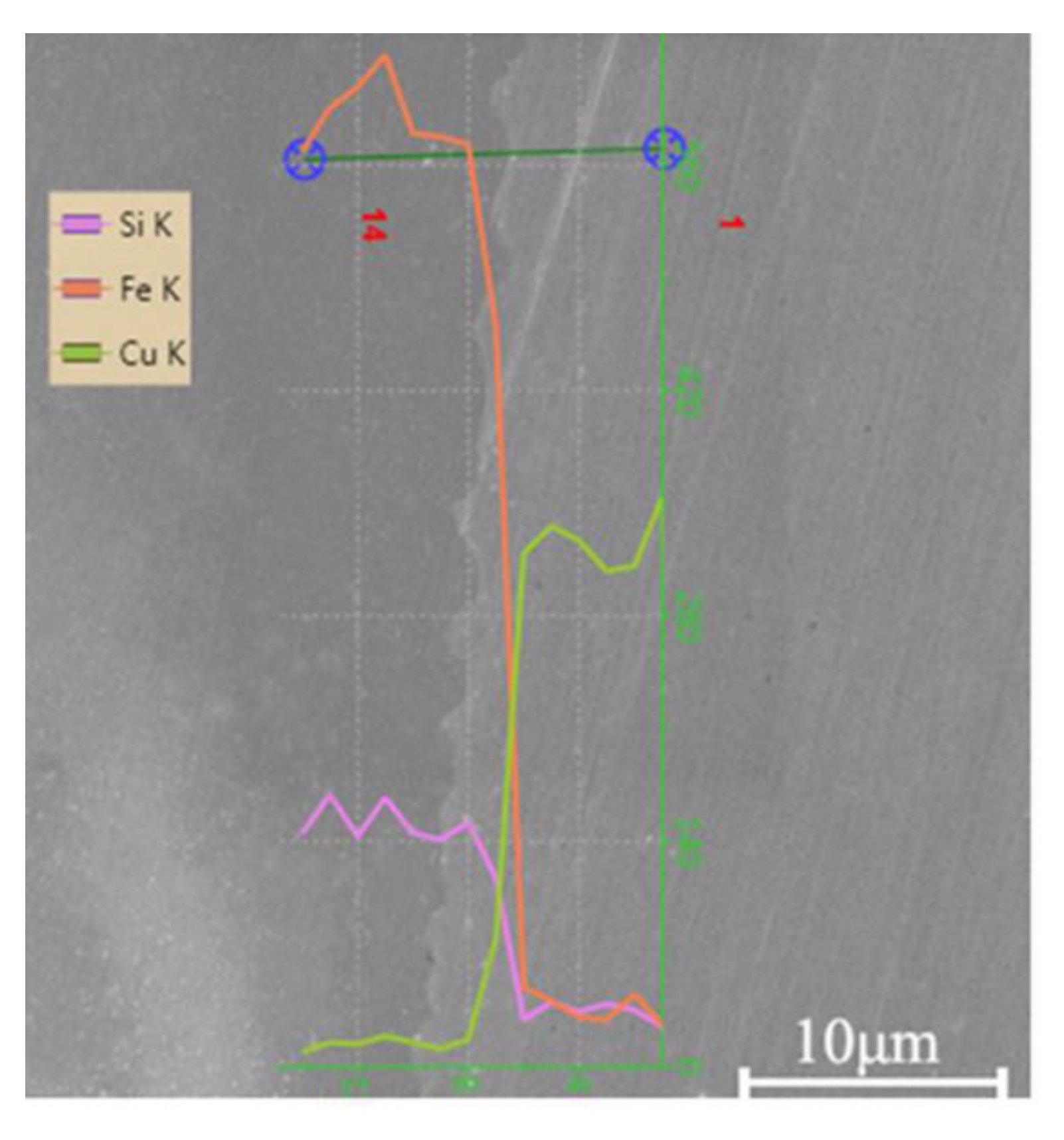
3.3.2. Laser Impact Welding Interface Diffusion and Intermetallic Compounds

At the impact welding interface with the corresponding occurring obvious melting phenomenon, the atom diffusion mechanism is the same as that in the melting and welding process, and intermetallic compounds forms. This kind of regional melting phenomenon is common in explosive welding and magnetic pulse welding/foil vaporization welding interface. Wang X et al. [27] found that laser impact welding also showed a local melting lump as shown in Figure 13 at high welding input energy, and a platform also appeared on the EDS (Energy Dispersive Spectrometer) concentration curve. According to previous studies by Akbari and Behnagh [51] and Zhang et al. [33], it is an intermetallic compound. Therefore, in laser impact welding, with high laser energy, melting at the interface also occurs. EDS can only qualitatively analyze the existing problems of intermetallic compounds. In-depth analysis is still needed for the composition and shape of intermetallic compounds.
For laser impact welding, the interface is generally no obvious melting phenomenon and the intermetallic compounds [24]. For example, Wang et al. [52] studied the laser impact welding of amorphous and crystalline materials. They used XRD to compare and analyze the changes in amorphous materials before and after laser impact welding. As shown in Figure 14, the EDS curve is the same as other materials. It is a continuous curve and no intermetallic compounds were found. In addition, they found that LIW could not cause structural changes in the amorphous matrix.
Chen S et al. [53] and Ning L et al. [54] found that the crystal structure at the interface was destroyed during an impact, resulting in a disordered organization. The two elements diffused and interacted with each other in a disordered structure, then, followed into the interior of the ordered crystal structure. Although the calculated diffusion layer thickness is slightly lower than the experimentally measured diffusion layer thickness, it provides an effective way to study atomic diffusion at the impact welding interface. This numerical simulation calculation result is consistent with “liquid film”, that is, the key to the inter-diffusion of LIW across the bonding interface is the disordered layer of atoms produced by the impact. In the future, high-precision characterization technology and numerical simulation technology are expected to reveal the atomic diffusion mechanism of laser impact welding interface.

4. Mechanical Properties of Laser Impact Welding Interface

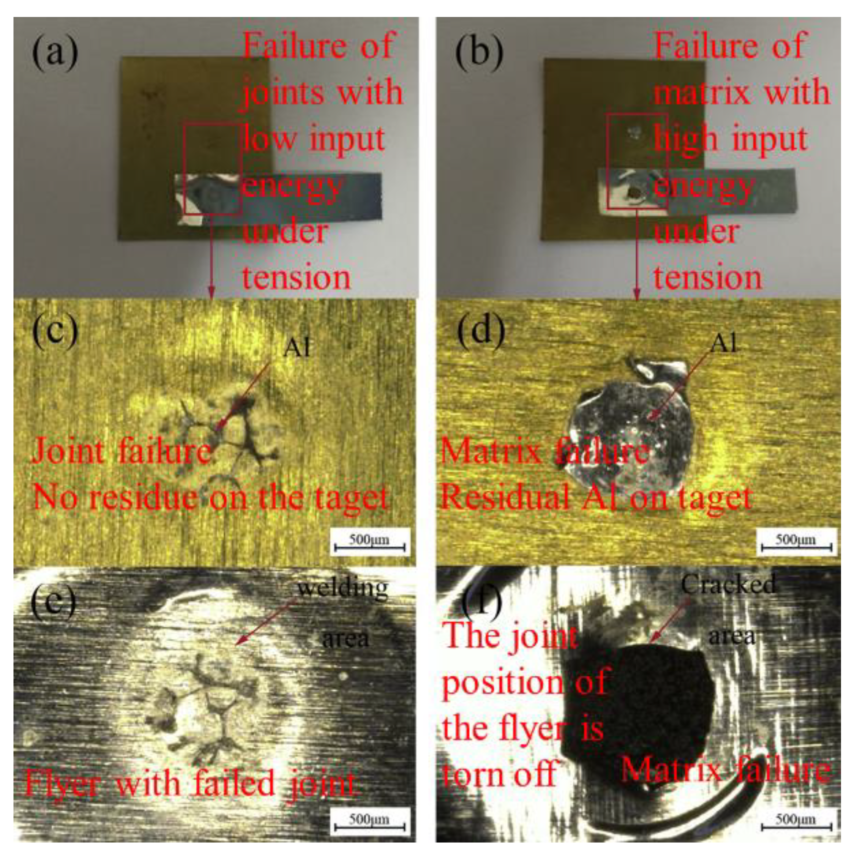
4.1. Laser Impact Welding Interface Strength

The welding area of laser impact welding is a millimeter-sized ring, and it is difficult to measure its area under mechanical testing in real-time. Therefore, the maximum force (N) that can be achieved in the tensile fracture of the welded joint is usually used to characterize the bonding performance of the welded joint. The test methods mainly include the peeling test and shearing test [24,28], as shown in Figure 15.
The mechanical properties of laser impact welded joints are generally considered to be related to energy density, welding area, and flyer thickness. The improvement of bonding force is affected by the higher the energy density, the larger the welding area, and the thicker the flying piece. As mentioned above, the higher the energy density, which leads to more generation of interface waves. It can be seen as increasing the bonding force by increasing the welding area and “mechanical interlocking”.
According to the failure location, laser impact welding can be divided into joint damage failures under low energy state and matrix damage failures under high energy state. The joint failure under low input energy is shown in Figure 16a,c,e. The joint bonding force is lower than the strength of the matrix, and the failure location is located in the joint, which is mostly brittle fracture; the matrix fails under high input energy. As shown in Figure 16b,d,f, the strength of the metallurgical joint is higher than the strength of the matrix, and the failure location is in the matrix, which is generally ductile fracture. Therefore, when the input energy is low, the input energy can be increased to increase the joint bonding force, and when the input energy is high, the thickness of the weldment can be increased to directly strengthen the target material and improve the damage resistance [27].

4.2. Interface Hardness of Laser Impact Welding

In addition to the bonding force, the nanoindentation experiment is used to test the hardness of the tiny interface area to characterize its strengthening under the high-speed impact. As shown in Figure 17, the laser impact welding joint is impact-strengthened, and the hardness is higher. The hardness of the matrix on both sides of the joint gradually decreases from the interface. However, the hardening effect is different for LIW (Laser Impact Welding) and MPW (Magnetic Pulse Welding) due to the different input energy. The higher hardness at the same position is affected by the more energy input [33].
Laser impact welding is a transient, high-temperature, and high-pressure process. The microstructure of the material undergoes abrupt changes, such as the increase in dislocations, the refinement of grains, and the formation of cellular structures, which change the properties of the material. On the one hand, the welded joint produces high-rate strain plastic deformation strengthening under impact; on the other hand, the rapid plastic deformation during the impact process will generate a lot of heat and cool down in a short period, which can be regarded as a quenching process [28,33,55,56].
However, it should be noted that the formation of brittle intermetallic compounds will also significantly increase its hardness. Therefore, to evaluate its performance, the bonding force of the welded joint and its hardening degree should be considered together.

5. Conclusions and Prospects

The principle and process of impact welding are described, and the difference between laser impact welding and another impact welding is illustrated above in this work. It also describes the research progress in recent years, and summarizes its application prospects, the difficulties in industrial applications and the mechanism problems currently to be studied as follows:
  • In the laboratory research stage, the development of laser impact welding technology has made great progress, realizing the joining between a variety of dissimilar materials, including the joining between amorphous and crystalline and multilayer composite materials. It shows that laser impact welding has a good application prospect in the joining of dissimilar materials.
  • Laser impact welding still has problems such as the rebound of the flyer, the surface damage of the flyer, and the small welding area. It is necessary to use a higher energy laser to try a larger welding area and use a “buffer layer” to solve the problem of center spring back. Before industrial applications, it is necessary to further optimize the laser impact welding process and design evaluation standards for the performance of welded joints.
  • The evolution of the microstructure of the laser impact welding interface is complex, the mechanism of interface atom diffusion is not clear, and the existence of micro-domain melting at the interface has not been confirmed. The discovery of the interface bonding mechanism requires more in-depth research on the atomic scale.

Author Contributions

Conceptualization, H.W.; Investigation, K.W., H.W., H.Z. and A.X.; Writing—Original Draft Preparation, K.W., H.Z. and H.W.; Writing—Review & Editing, K.W., H.W. and W.Z. All authors have read and agreed to the published version of the manuscript.

Funding

This work was supported by Beijing Municipal Science and Technology (Z201100004520011), National Natural Science Foundation of China (61409220124), Fundamental Research Funds for the Central Universities (06500107).

Acknowledgments

The authors thank all the lab members for the discussion and help. Particularly, the authors appreciate the excellent research work from the researchers included in this review.

Conflicts of Interest

The authors declare no conflict of interest.

References

  1. Liu, H.; Gong, J.; Ma, Y.; Cui, J.; Li, M.; Wang, X. Investigation of novel laser shock hydroforming method on micro tube bulging. Opt. Lasers Eng. 2020, 129, 106073. [Google Scholar] [CrossRef]
  2. Chen, Y.; Nakata, K. Microstructural characterization and mechanical properties in friction stir welding of aluminum and titanium dissimilar alloys. Mater. Des. 2009, 30, 469–474. [Google Scholar] [CrossRef]
  3. Oliveira, J.; Schell, N.; Zhou, N.; Wood, L.; Benafan, O. Laser welding of precipitation strengthened Ni-rich NiTiHf high temperature shape memory alloys: Microstructure and mechanical properties. Mater. Des. 2019, 162, 229–234. [Google Scholar] [CrossRef]
  4. Oliveira, J.; Curado, T.; Zeng, Z.; Lopes, J.; Rossinyol, E.; Park, J.M.; Schell, N.; Fernandes, F.B.; Kim, H.S. Gas tungsten arc welding of as-rolled CrMnFeCoNi high entropy alloy. Mater. Des. 2020, 189, 108505. [Google Scholar] [CrossRef]
  5. Fronczek, D.M.; Wojewoda-Budka, J.; Chulist, R.; Sypien, A.; Korneva, A.; Szulc, Z.; Schell, N.; Zieba, P. Structural properties of Ti/Al clads manufactured by explosive welding and annealing. Mater. Des. 2016, 91, 80–89. [Google Scholar] [CrossRef]
  6. Arya, H.K.; Saxena, R.K.; Kumar, R. Effect of Heat Input on Residual Stress in Submerged Arc Welding; LAMBERT Academic Publishing: Rīgā, Latvia, 2014; ISBN 13: 978-3-659-66032-0. [Google Scholar]
  7. Ishigami, A.; Roy, M.; Walsh, J.N.; Withers, P.J. The effect of the weld fusion zone shape on residual stress in submerged arc welding. Int. J. Adv. Manuf. Technol. 2016, 90, 3451–3464. [Google Scholar] [CrossRef]
  8. Mehta, K.P.; Carlone, P.; Astarita, A.; Scherillo, F.; Rubino, F.; Vora, P. Conventional and cooling assisted friction stir welding of AA6061 and AZ31B alloys. Mater. Sci. Eng. A 2019, 759, 252–261. [Google Scholar] [CrossRef]
  9. Ni, Z.; Yang, J.; Gao, Z.; Hao, Y.; Chen, L.; Ye, F. Joint formation in ultrasonic spot welding of aluminum to copper and the effect of particle interlayer. J. Manuf. Process. 2020, 50, 57–67. [Google Scholar] [CrossRef]
  10. Mousavi, S.A.; Sartangi, P.F. Experimental investigation of explosive welding of cp-titanium/AISI 304 stainless steel. Mater. Des. 2009, 30, 459–468. [Google Scholar] [CrossRef]
  11. Pereira, D.; Oliveira, J.; Santos, T.; Miranda, R.; Lourenço, F.; Gumpinger, J.; Bellarosa, R. Aluminium to Carbon Fibre Reinforced Polymer tubes joints produced by magnetic pulse welding. Compos. Struct. 2019, 230, 111512. [Google Scholar] [CrossRef]
  12. Watanabe, T.; Takayama, H.; Yanagisawa, A. Joining of aluminum alloy to steel by friction stir welding. J. Mater. Process. Technol. 2006, 178, 342–349. [Google Scholar] [CrossRef]
  13. Wang, K.; Shriver, D.; Li, Y.; Banu, M.; Hu, S.; Xiao, G.; Arinez, J.; Fan, H.-T. Characterization of weld attributes in ultrasonic welding of short carbon fiber reinforced thermoplastic composites. J. Manuf. Process. 2017, 29, 124–132. [Google Scholar] [CrossRef]
  14. Daehn, G.S.; Lippold, J.C. Low-Temperature Spot Impact Welding Driven without Contact. WO/2009/111,774, 11 September 2009. [Google Scholar]
  15. Wu, A.; Song, Z.; Nakata, K.; Liao, J.; Zhou, L. Interface and properties of the friction stir welded joints of titanium alloy Ti6Al4V with aluminum alloy 6061. Mater. Des. 2015, 71, 85–92. [Google Scholar] [CrossRef]
  16. Lawrence, R.; Trott, W.M. Theoretical analysis of a pulsed-laser-driven hypervelocity flyer launcher. Int. J. Impact Eng. 1993, 14, 439–449. [Google Scholar] [CrossRef]
  17. Paisley, D.L. Laser-Driven Miniature Flyer Plates For Shock Initiation Of Secondary Explosives. In Proceedings of the American Physical Society Topical Conference on Shock Compression of Condensed Matter, Albuquerque, NM, USA, 14–17 August 1989. [Google Scholar]
  18. Wang, H.; Wang, Y. Characteristics of Flyer Velocity in Laser Impact Welding. Metals 2019, 9, 281. [Google Scholar] [CrossRef] [Green Version]
  19. Crossland, B. Explosive Welding of Metals and Its Application; Clarendon Press: Oxford, UK, 1982. [Google Scholar]
  20. Blazynski, T. Explosive Welding, Forming and Compaction; Springer: Dordrecht, The Netherland, 1983. [Google Scholar]
  21. Katzenstein, J. System and Method for Impact Welding by Magnetic Implosion. U.S. Patent 4,513,188, 23 April 1985. [Google Scholar]
  22. Daehn, G.S.; Lippold, J.; Liu, D.; Taber, G.; Wang, H. Laser impact welding—Process introduction and key variables. In Proceedings of the International Conference on High Speed Forming, Dortmund, Germany, 24–26 April 2012; Volume 2012. [Google Scholar]
  23. Szecket, A. Impact Welding. U.S. Patent 4,842,182, 27 June 1989. [Google Scholar]
  24. Wang, H.; Vivek, A.; Taber, G.; Daehn, G. Laser impact welding application in joining aluminum to titanium. J. Laser Appl. 2016, 28, 32002. [Google Scholar] [CrossRef]
  25. Wang, H.; Wang, Y. High-Velocity Impact Welding Process: A Review. Metals 2019, 9, 144. [Google Scholar] [CrossRef] [Green Version]
  26. Wang, H.; Taber, G.; Liu, D.; Hansen, S.; Chowdhury, E.; Terry, S.; Lippold, J.C.; Daehn, G.; Taber, G.A.; Hansen, S.R. Laser impact welding: Design of apparatus and parametric optimization. J. Manuf. Process. 2015, 19, 118–124. [Google Scholar] [CrossRef]
  27. Wang, X.; Shao, M.; Jin, H.; Tang, H.; Liu, H. Laser impact welding of aluminum to brass. J. Mater. Process. Technol. 2019, 269, 190–199. [Google Scholar] [CrossRef]
  28. Wang, X.; Tang, H.; Shao, M.; Jin, H.; Liu, H. Laser impact welding: Investigation on microstructure and mechanical properties of molybdenum-copper welding joint. Int. J. Refract. Met. Hard Mater. 2019, 80, 1–10. [Google Scholar] [CrossRef]
  29. Zhang, Z.; Liu, M. Numerical studies on explosive welding with ANFO by using a density adaptive SPH method. J. Manuf. Process. 2019, 41, 208–220. [Google Scholar] [CrossRef]
  30. Wang, X.; Li, F.; Huang, T.; Wang, X.; Liu, H. Experimental and numerical study on the laser shock welding of aluminum to stainless steel. Opt. Lasers Eng. 2019, 115, 74–85. [Google Scholar] [CrossRef]
  31. Liu, H.; Jin, H.; Shao, M.; Tang, H.; Wang, X. Investigation on Interface Morphology and Mechanical Properties of Three-Layer Laser Impact Welding of Cu/Al/Cu. Met. Mater. Trans. A 2018, 50, 1273–1282. [Google Scholar] [CrossRef]
  32. Sadeh, S.; Gleason, G.H.; Hatamleh, M.I.; Sunny, S.F.; Yu, H.; Malik, A.; Qian, D. Simulation and Experimental Comparison of Laser Impact Welding with a Plasma Pressure Model. Metals 2019, 9, 1196. [Google Scholar] [CrossRef] [Green Version]
  33. Zhang, Y.; Babu, S.S.; Prothe, C.; Blakely, M.; Kwasegroch, J.; Laha, M.; Daehn, G.S. Application of high velocity impact welding at varied different length scales. J. Mater. Process. Technol. 2011, 211, 944–952. [Google Scholar] [CrossRef]
  34. Bahrani, A.S.; Black, T.J.; Crossland, B. The mechanics of wave formation in explosive welding. Proc. R. Soc. London. Ser. A Math. Phys. Sci. 1967, 296, 123–136. [Google Scholar] [CrossRef]
  35. Abrahamson, G.R. Permanent Periodic Surface Deformations Due to a Traveling Jet. J. Appl. Mech. 1961, 28, 519–528. [Google Scholar] [CrossRef]
  36. Hunt, J.N. Wave formation in explosive welding. Philos. Mag. 1968, 17, 669–680. [Google Scholar] [CrossRef]
  37. Ben-Artzy, A.; Stern, A.; Frage, N.; Shribman, V.; Sadot, O. Wave formation mechanism in magnetic pulse welding. Int. J. Impact Eng. 2010, 37, 397–404. [Google Scholar] [CrossRef]
  38. Godunov, S.; Deribas, A.; Zabrodin, A.; Kozin, N. Hydrodynamic effects in colliding solids. J. Comput. Phys. 1970, 5, 517–539. [Google Scholar] [CrossRef]
  39. Godunov, S.K.; Deribas, A.A.; Kozin, N.S. Wave formation in explosive welding. J. Appl. Mech. Tech. Phys. 1973, 12, 398–406. [Google Scholar] [CrossRef]
  40. Reid, S.R.; Sherif, N.H.S. Prediction of the Wavelength of Interface Waves in Symmetric Explosive Welding. J. Mech. Eng. Sci. 1976, 18, 87–94. [Google Scholar] [CrossRef]
  41. Kowalick, J.; Hay, D. A mechanism of explosive bonding. Metall. Trans. 1971, 2, 1953–1958. [Google Scholar] [CrossRef]
  42. Zhang, Z.; Feng, D.; Liu, M. Investigation of explosive welding through whole process modeling using a density adaptive SPH method. J. Manuf. Process. 2018, 35, 169–189. [Google Scholar] [CrossRef]
  43. Nassiri, A.; Abke, T.; Daehn, G. Investigation of melting phenomena in solid-state welding processes. Scr. Mater. 2019, 168, 61–66. [Google Scholar] [CrossRef]
  44. Göbel, G.; Kaspar, J.; Herrmannsdörfer, T.; Brenner, B.; Beyer, E. Insights into intermetallic phases on pulse welded dissimilar metal joints. In Proceedings of the 4th International Conference High Speed Form, Columbus, OH, USA, 9–10 March 2010. [Google Scholar] [CrossRef]
  45. Kore, S.D.; Imbert, J.; Worswick, M.J.; Zhou, Y. Electromagnetic impact welding of Mg to Al sheets. Sci. Technol. Weld. Join. 2009, 14, 549–553. [Google Scholar] [CrossRef]
  46. Stern, A.; Aizenshtein, M.; Moshe, G.; Cohen, S.R.; Frage, N. The Nature of Interfaces in Al-1050/Al-1050 and Al-1050/Mg-AZ31 Couples Joined by Magnetic Pulse Welding (MPW). J. Mater. Eng. Perform. 2013, 22, 2098–2103. [Google Scholar] [CrossRef]
  47. Stern, A.; Shribman, V.; Ben-Artzy, A.; Aizenshtein, M. Interface Phenomena and Bonding Mechanism in Magnetic Pulse Welding. J. Mater. Eng. Perform. 2014, 23, 3449–3458. [Google Scholar] [CrossRef]
  48. Marya, M.; Marya, S.; Priem, D. On The Characteristics of Electromagnetic Welds Between Aluminium and other Metals and Alloys. Weld. World 2005, 49, 74–84. [Google Scholar] [CrossRef]
  49. Sridharan, N.; Poplawsky, J.D.; Vivek, A.; Bhattacharya, A.; Guo, W.; Meyer, H.; Mao, Y.; Lee, T.; Daehn, G. Cascading microstructures in aluminum-steel interfaces created by impact welding. Mater. Charact. 2019, 151, 119–128. [Google Scholar] [CrossRef]
  50. Wang, H.; Liu, D.; Lippold, J.C.; Daehn, G.S. Laser impact welding for joining similar and dissimilar metal combinations with various target configurations. J. Mater. Process. Technol. 2020, 278, 116498. [Google Scholar] [CrossRef]
  51. Akbari, M.; Behnagh, R.A. Dissimilar Friction-Stir Lap Joining of 5083 Aluminum Alloy to CuZn34 Brass. Met. Mater. Trans. A 2012, 43, 1177–1186. [Google Scholar] [CrossRef]
  52. Wang, X.; Luo, Y.; Huang, T.; Liu, H. Experimental Investigation on Laser Impact Welding of Fe-Based Amorphous Alloys to Crystalline Copper. Materials 2017, 10, 523. [Google Scholar] [CrossRef] [Green Version]
  53. Chen, S.Y.; Wu, Z.W.; Liu, K.X.; Li, X.J.; Luo, N.; Lu, G.X. Atomic diffusion behavior in Cu-Al explosive welding process. J. Appl. Phys. 2013, 113, 044901. [Google Scholar] [CrossRef]
  54. Luo, N.; Shen, T.; Junxiang, X. Diffusion Mechanism of Explosive Welding Interface Between Memory Alloy Ni 50 Ti 50 and Cu. Xiyou Jinshu Cailiao Yu Gongcheng Rare Met. Mater. Eng. 2018, 47, 3238–3242. [Google Scholar]
  55. Zhang, Y.; Babu, S.; Daehn, G. Interfacial ultrafine-grained structures on aluminum alloy 6061 joint and copper alloy 110 joint fabricated by magnetic pulse welding. J. Mater. Sci. 2010, 45, 4645–4651. [Google Scholar] [CrossRef]
  56. Lee, K.-J.; Kumai, S.; Arai, T.; Aizawa, T. Interfacial microstructure and strength of steel/aluminum alloy lap joint fabricated by magnetic pressure seam welding. Mater. Sci. Eng. A 2007, 471, 95–101. [Google Scholar] [CrossRef]
Figure 1. (a) Surface indentation of ultrasonic welding (reproduced from [9], with permission of Elsevier 2020); (b) Intermetallic compound layer with friction stir welding (reproduced from [15], with permission of Elsevier 2015).
Metals 10 01444 g001
Figure 2. Atomic force-distance curve.
Metals 10 01444 g002
Figure 3. (a) Schematic diagram of laser impact welding system; (b) flat-top laser energy distribution; (c) Gaussian laser energy distribution.
Metals 10 01444 g003
Figure 4. Schematic diagram of laser impact welding process (reproduced from [28], with permission of Elsevier 2019). (a) Excitation stage: The laser irradiates the ablation layer through the confinement layer, and the ablation layer is vaporized into plasma. Due to the limitation of the confinement layer, the reaction force of the plasma drives the flyer to emit; (b) Flight phase: the flyer passes the preset flight distance (standoff) and collides with the target at a certain speed and angle; (c) Welding stage: The behavior of the impact point is shown in Figure 5 (the welded area on the left). The flyer and the target collide at a certain angle from the starting position of the metallurgical bonding to the end position and the welding is over.
Metals 10 01444 g004
Figure 5. Schematic diagram of the impact welding process.
Metals 10 01444 g005
Figure 6. Generic welding window (reproduced from [10], with permission of Elsevier 2019).
Metals 10 01444 g006
Figure 7. (a) Cross-section of weld interface at 1550 mJ energy (reprodueced from [27], with permission of Elsevier 2019); (be) Weld spot between molybdenum and copper (reproduced from [28], with permission of Elsevier 2019).
Metals 10 01444 g007
Figure 8. Weld interface morphology of three typical impact welded joints with (a) Explosive welding; (b) Magnetic pulse welding; (c) Laser impact welding; (d) Weld wave interface morphology with laser impact welding (reproduced from [24], with permission of Laser Institute of America 2016).
Metals 10 01444 g008
Figure 9. (ae) the process of Bahrani caved mechanism (reproduce from [34], with permission of Royal Society 1967).
Metals 10 01444 g009
Figure 10. (a) Helmholz instability mechanism (reproduced from [37], with permission of Elsevier 2010); (b) stress wave mechanism.
Metals 10 01444 g010
Figure 11. Vortex Street mechanism (reproduced from [42], with permission of Elsevier 2018).
Metals 10 01444 g011
Figure 12. Two welding interfaces of impact welding (a) Transition zone interface (reproduced from [49], with permission of Elsevier 2019); (b) Interface without transition zone (reproduced from [24], with permission of Laser Institute of America 2016).
Metals 10 01444 g012
Figure 13. EDS (Energy Dispersive Spectrometer) curves of impact weld melting block (reproduced from [27], with permission of Elsevier 2019) (a) SEM image of aluminum/copper weld interface with fusion block; (b,c) EDS curves at positions 1 and 2.
Metals 10 01444 g013
Figure 14. EDS concentration curve for laser impact welding of crystal and amorphous materials [52].
Metals 10 01444 g014
Figure 15. Test method for bonding force of welded joints (a) shearing test and result (reproduced from [28], with permission of Elsevier 2019); (b) peeling test and result (reproduced from [24] with permission of Laser Institute of America 2016).
Metals 10 01444 g015
Figure 16. Two forms of failure (reproduced from [27], with permission of Elsevier 2019) (a,c,e) Low-energy joint failure; (b,d,f) High-energy base metal failure.
Metals 10 01444 g016
Figure 17. Hardness of weld interface with MPW (Magnetic Pulse Welding) and LIW (Laser Impact Welding) (reproduced from [33], with permission of Elsevier 2011).
Metals 10 01444 g017
Table 1. Influence of Weldment Combination Parameters.
Weldment Combination ParametersInfluence of Impact Welding
Confinement layerThe higher the hardness, the greater the reaction force on the flyer, and the higher the impact speed under the same energy; but when the hardness of the confinement layer is high, the toughness is poor, and the service life is shorter in the continuous high-speed impact service environment. Currently, the commonly used material is polycarbonate and high light transmission glass
BinderLiquid super glue has high performance and can reach the highest speed, but it is difficult to spread evenly; solid double-sided glue spreads evenly, but it will lose a certain amount of energy due to self-adhesion. Therefore, its impact speed is lower than that of liquid super glue.
Ablative layerThe ablation layer is excited by the laser to form plasma to accelerate the flyer. The stronger its ability to absorb laser energy, the more plasma formed, and the higher the conversion efficiency of light energy to kinetic energy. Currently, black spray paint is commonly used
Thickness of flyerThe thicker the flyer, the larger the mass and the smaller the impact speed; however, as the thickness increases, the thickness of the welded joint becomes larger, thereby improving the joint strength
Preset flying distanceThe laser-driven flyer flight is a variable speed process. First, it accelerates and then decelerates. Under certain conditions, there is an optimal position for the highest impact velocity.
Publisher’s Note: MDPI stays neutral with regard to jurisdictional claims in published maps and institutional affiliations.

