Estimation of Critical Dimensions for the Crack and Pitting Corrosion Defects in the Oil Storage Tank Using Finite Element Method and Taguchi Approach


 ,
,  and
and 
Abstract
:1. Introduction
2. Types of Defects in the Oil Storage Tanks
- Defects due to inaccuracy in the construction, implementation and assembling of the structure.
- Defects that occur during the storage of oil and exploitation of reservoirs.
2.1. Pitting Corrosion
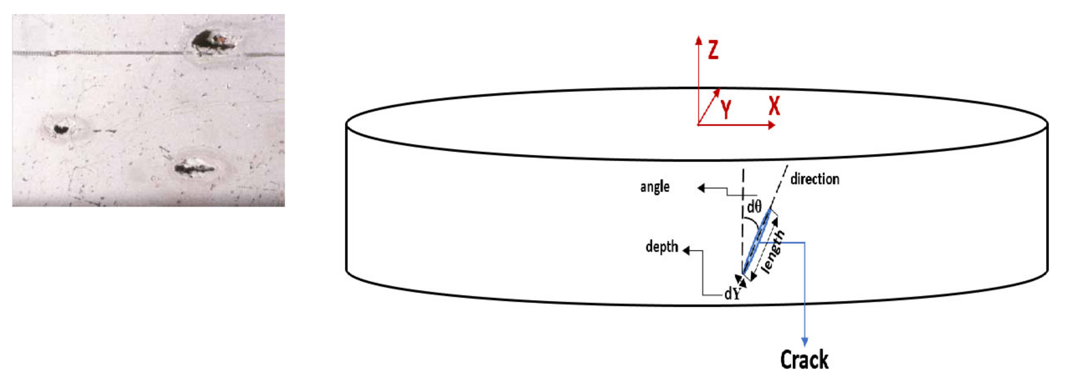
2.2. Crack
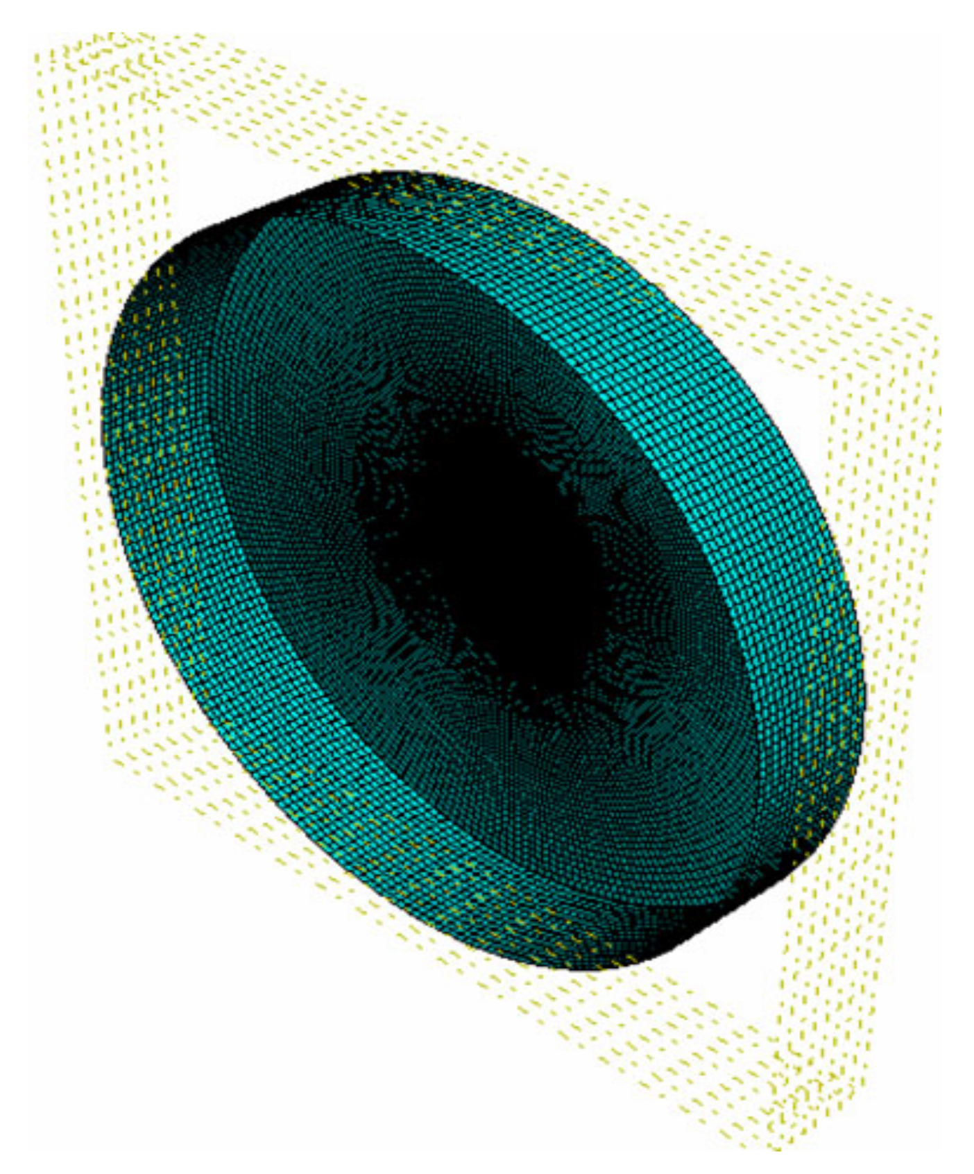
3. Finite Element Simulation
3.1. Analytical Solution
3.2. FE Solution
3.3. FE Model of Crack and Pitting Corrosion
4. Taguchi Approach
5. Results and Discussion
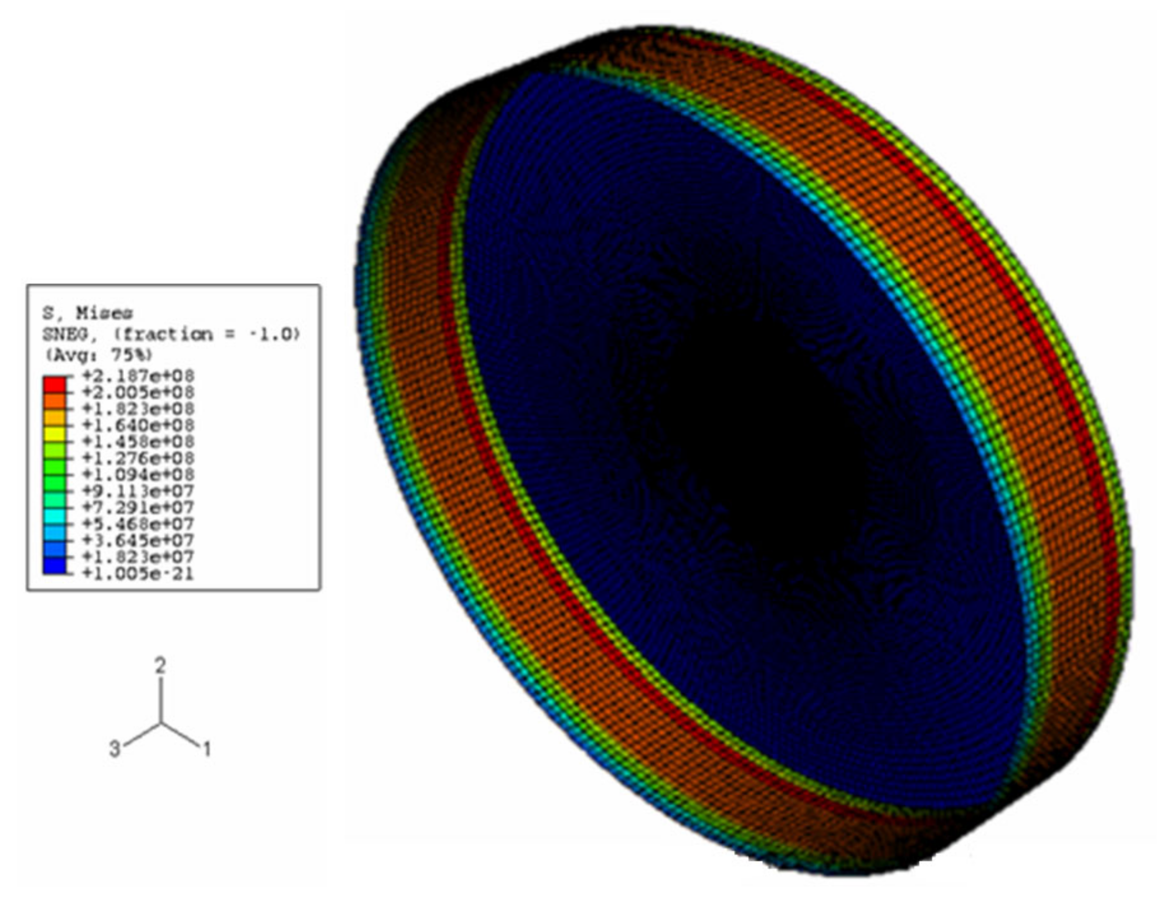
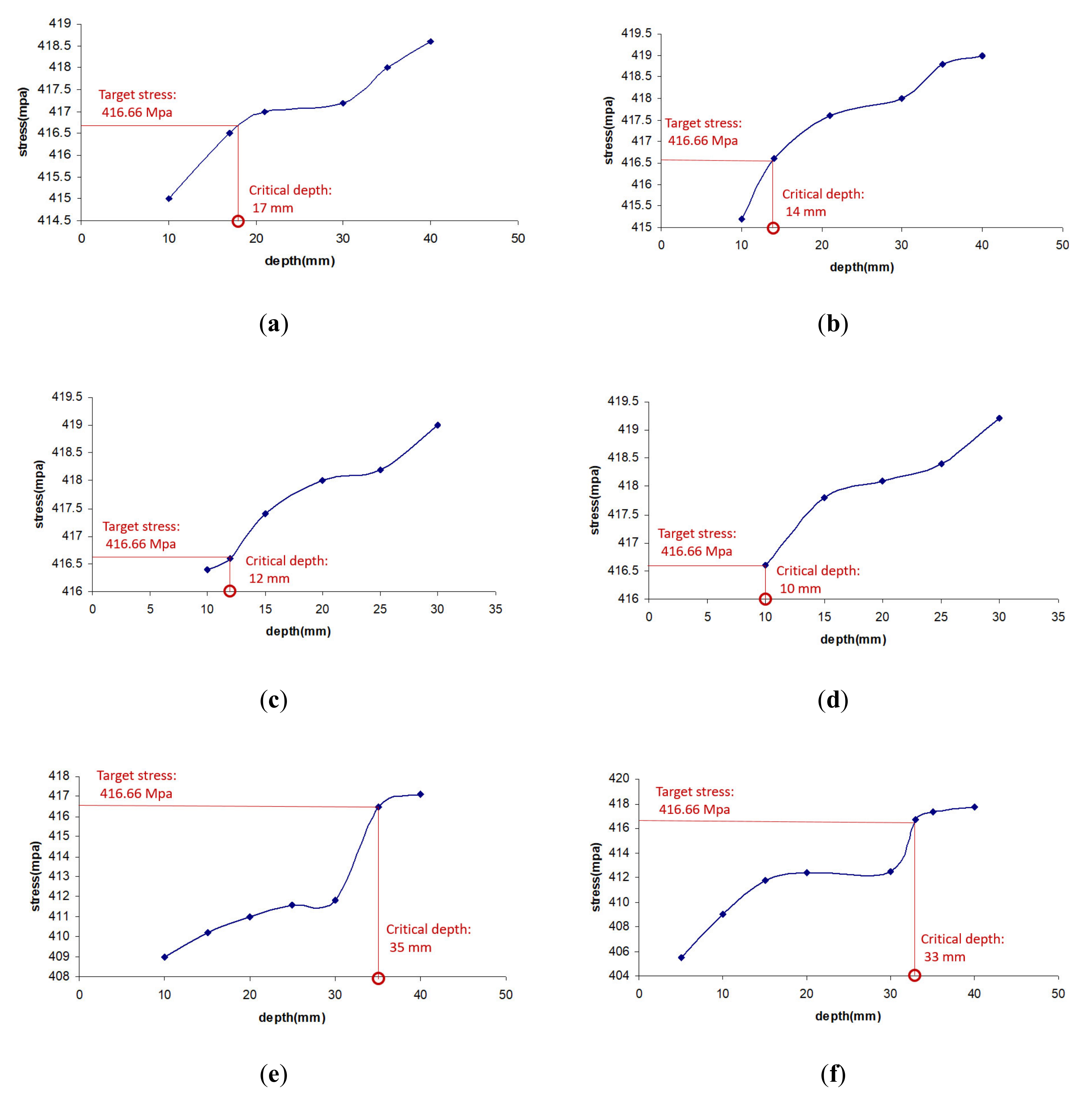
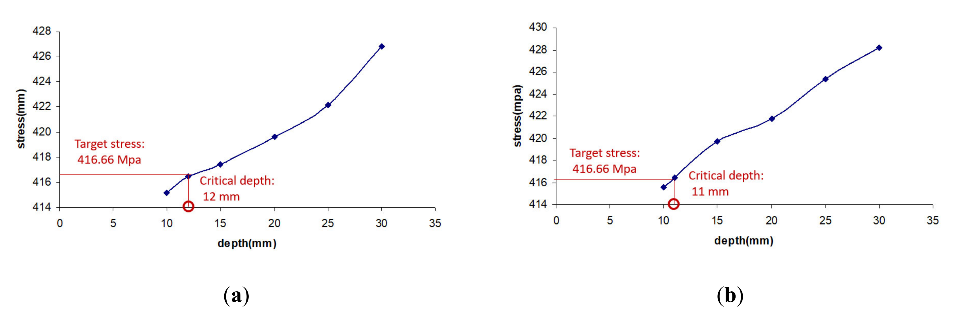
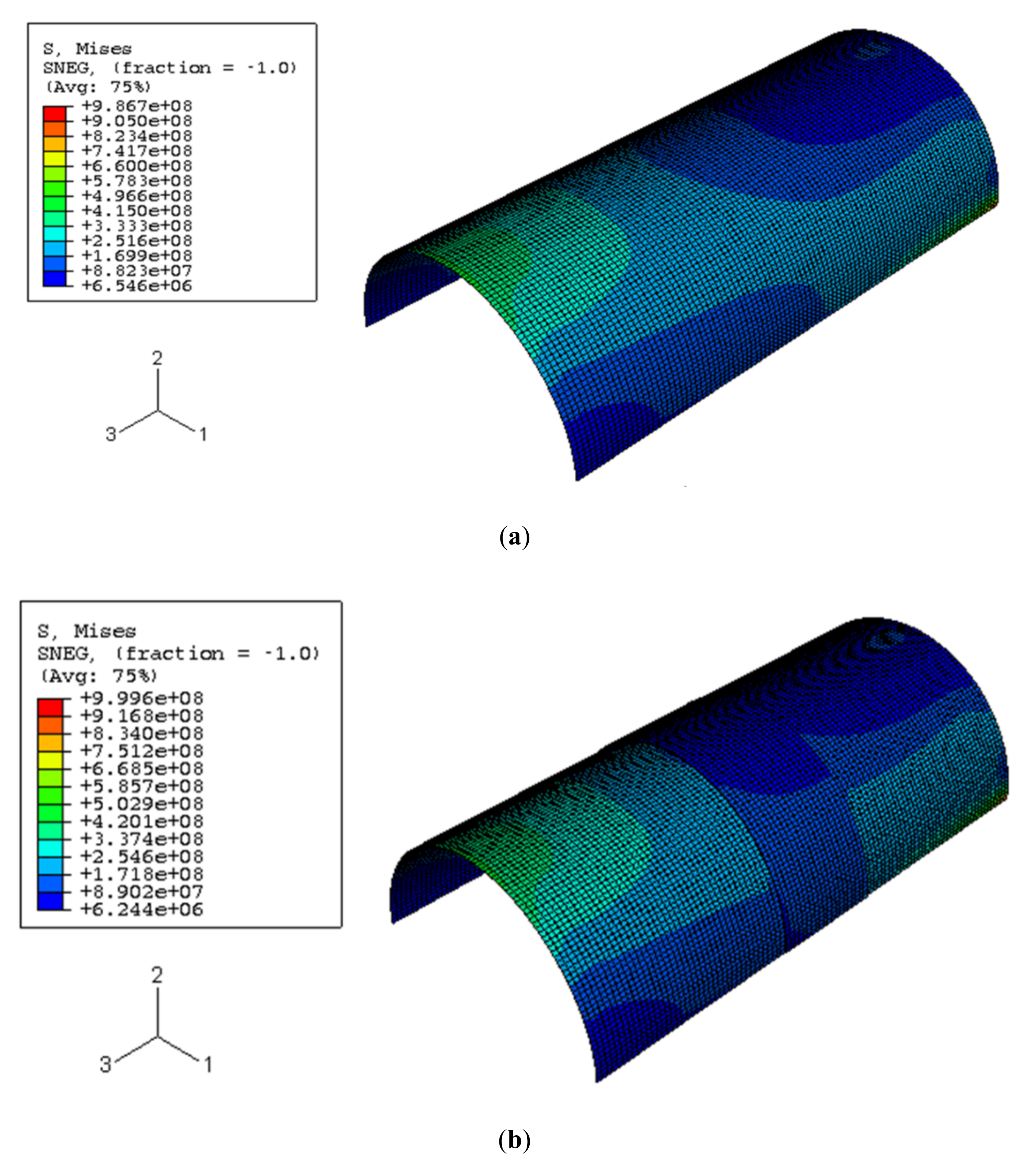
5.1. Finite Element Results
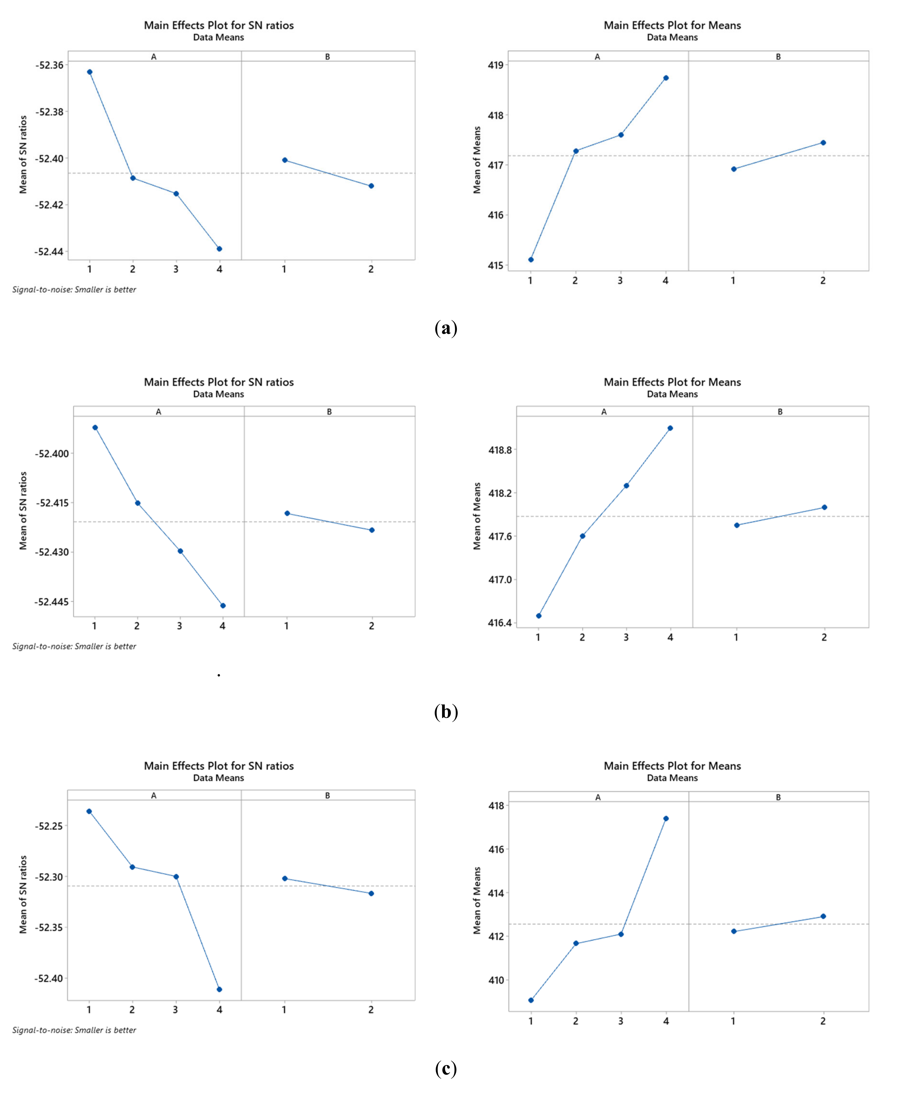
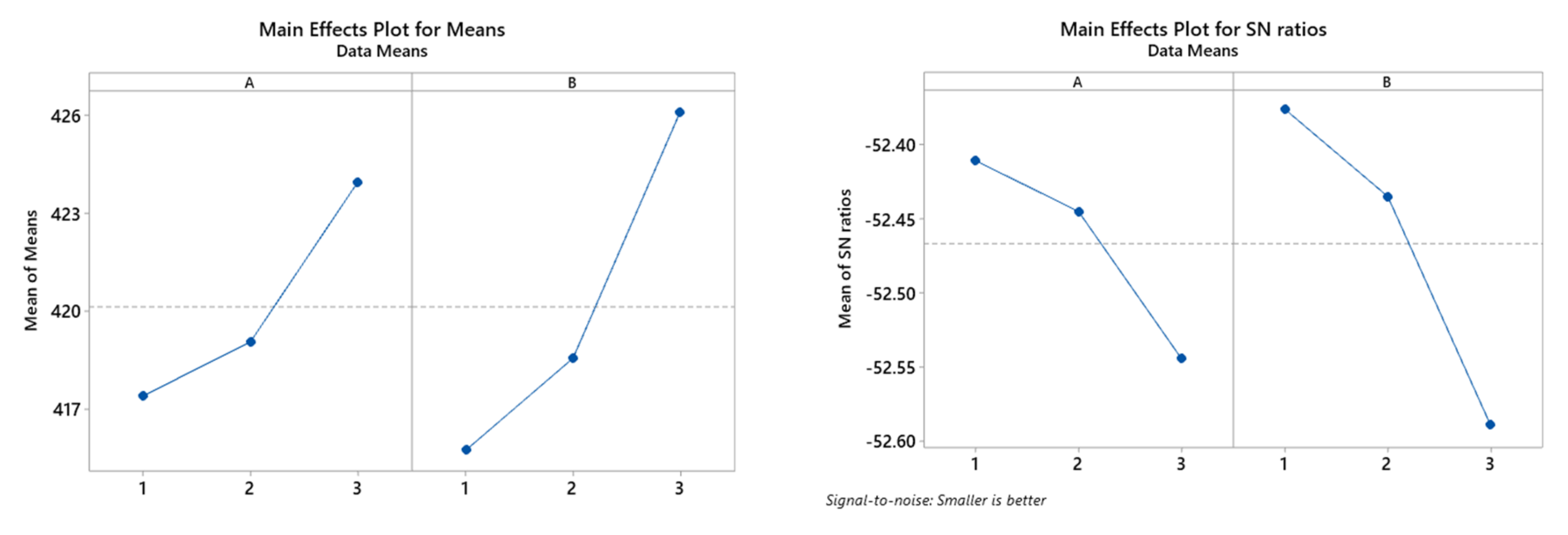
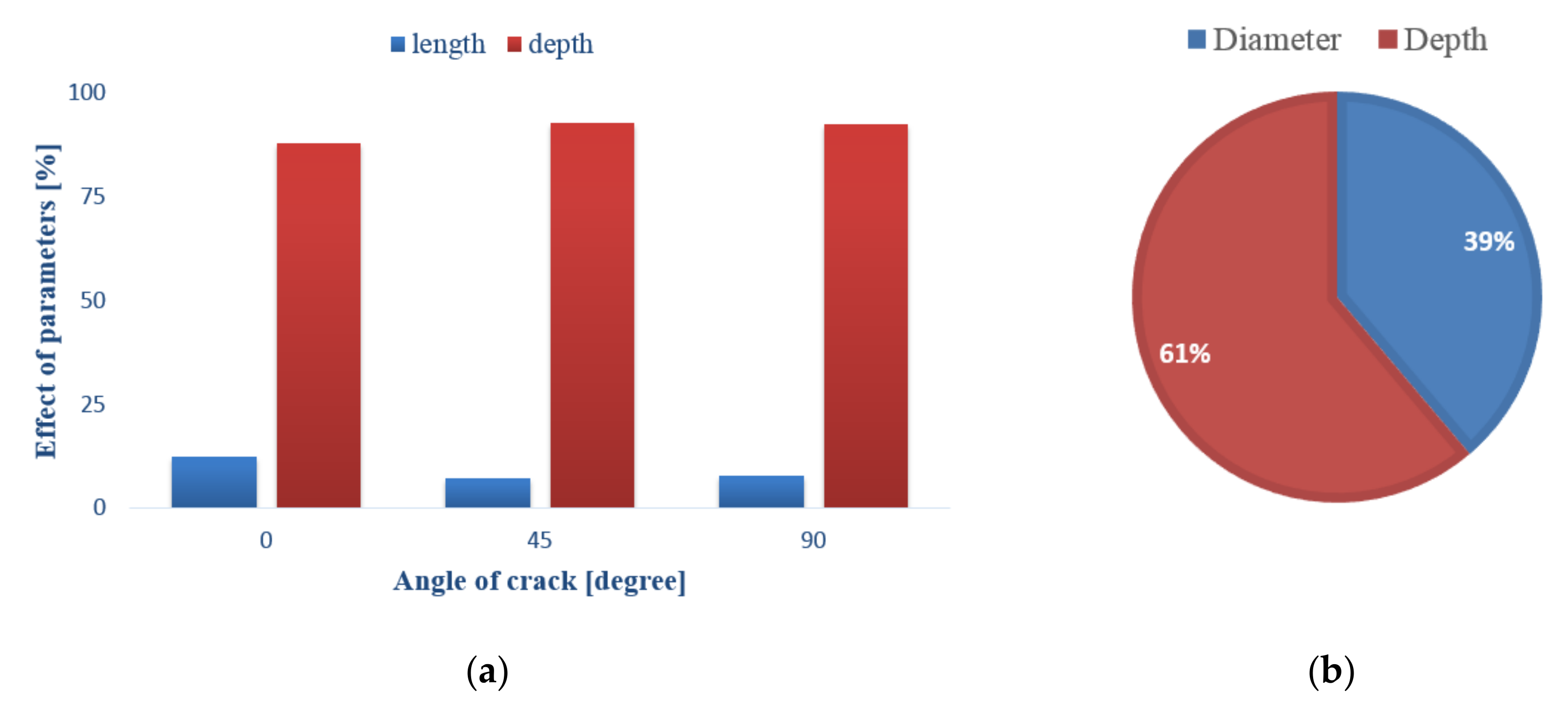
5.2. Taguchi Results
6. Conclusions
Author Contributions
Funding
Conflicts of Interest
References
- Underwood, J. Stress Intensity Factors for Internally Pressurized Thick-Wall Cylinders. Stress analysis and growth of cracks. ASTM STP 1997, 513, 59–70. [Google Scholar]
- Raju, I.S.; Newman, J. Stress-Intensity Factors for Internal and External Surface Cracks in Cylindrical Vessels. Int. J. Press. Vessel. Technol. 1982, 104, 293–298. [Google Scholar] [CrossRef]
- Carpinteri, A. Shape change of surface cracks in round bars under cyclic axial loading. Int. J. Fatigue 1993, 15, 21–26. [Google Scholar] [CrossRef]
- Carpinteri, A.; Brighenti, R.; Spagnoli, A. Part-through cracks in pipes under cyclic bending. Nucl. Eng. Des. 1998, 185, 1–10. [Google Scholar] [CrossRef]
- Fonte, M.; De Freitas, M. Stress Intensity Factors for semi-elliptical surface cracks in round bars under bending and torsion. Int. J. Fatigue 1999, 21, 457–463. [Google Scholar] [CrossRef]
- De Fonte, M.; Gomes, E.; De Freitas, M. Stress Intensity Factors for Semi-Elliptical Surface Cracks in Round Bars Subjected to Mode I (Bending) and Mode III (Torsion) Loading. Fatigue Des. Reliab. 1999, 25, 249–260. [Google Scholar] [CrossRef]
- Bhuyan, G.S.; Sperling, E.J.; Shen, G.; Yin, H.; Rana, M.D. Prediction of Failure Behavior of a Welded Pressure Vessel Containing Flaws During a Hydrogen-Charged Burst Test. J. Press. Vessel. Technol. 1999, 121, 246–251. [Google Scholar] [CrossRef]
- Carpinteri, A.; Brighenti, R.; Spagnoli, A. Fatigue growth simulation of part-through flaws in thick-walled pipes under rotary bending. Int. J. Fatigue 2000, 22, 1–9. [Google Scholar] [CrossRef]
- Toughiry, M. Development of Accept Reject Criteria for Requalification of High Pressure Steel and Aluminium Cylinders. STIN 2002, 3, 04229. [Google Scholar]
- Shahani, A.R.; Habibi, S.E. Calculation of stress intensity factors for semi-elliptical surface cracks in thick-walled cylinders under bending moment—Part II: Numerical simulation. In Proceedings of the 14th Annual International Conference of Iranian Society of Mechanical Engineering, Isfahan, Iran, 15–17 May 2006. [Google Scholar]
- Shahani, A.R.; Shoja, M.M.; Fazli, A.; Hosseinali, M. Calculation of stress intensity factors for semi-elliptical surface cracks in thick-walled cylinders under bending moment—Part I: Experimental observations. In Proceedings of the 14th Annual International Conference of Iranian Society of Mechanical Engineering, Isfahan, Iran, 15–17 May 2006. [Google Scholar]
- Wallbrink, C.; Peng, D.; Jones, R. Assessment of partly circumferential cracks in pipes. Int. J. Fract. 2005, 133, 167–181. [Google Scholar] [CrossRef]
- Shahani, A.R.; Habibi, S.E. Stress Intensity Factors in a Hallow Cylinder Containing a Circumferential Semi-Elliptical Crack Subjected to Combined Loading. Int. J. Fatigue 2006, 29, 128–140. [Google Scholar] [CrossRef]
- Kaptan, A.; Kisioglu, Y. Determination of burst pressures and failure locations of vehicle LPG cylinders. Int. J. Press. Vessel. Pip. 2007, 84, 451–459. [Google Scholar] [CrossRef]
- Kasai, N.; Fujiwara, Y.; Sekine, K.; Sakamoto, T. Evaluation of back-side flaws of the bottom plates of an oil-storage tank by the RFECT. NDT E Int. 2008, 41, 525–529. [Google Scholar] [CrossRef]
- Kim, J.-S.; An, D.-H.; Lee, S.-Y.; Lee, B. A failure analysis of fillet joint cracking in an oil storage tank. J. Loss Prev. Process. Ind. 2009, 22, 845–849. [Google Scholar] [CrossRef]
- Godoy, L.A.; Batista-Abreu, J.C. Buckling of fixed-roof aboveground oil storage tanks under heat induced by an external fire. Thin-Walled Struct. 2012, 52, 90–101. [Google Scholar] [CrossRef]
- Yang, L.; Chen, Z.; Cao, G.; Yu, C.; Guo, W. An analytical formula for elastic–plastic instability of large oil storage tanks. Int. J. Press. Vessel. Pip. 2013, 101, 72–80. [Google Scholar] [CrossRef]
- Kasai, N.; Mori, S.; Tamura, K.; Sekine, K.; Tsuchida, T.; Serizawa, Y. Predicting maximum depth of corrosion using extreme value analysis and Bayesian inference. Int. J. Press. Vessel. Pip. 2016, 146, 129–134. [Google Scholar] [CrossRef]
- Cheng, X.; Jing, W.; Yin, C.; Li, C. Stability parameter analysis of a composite foundation of an oil storage tank in a loess area treated with compaction piles. Soils Found. 2018, 58, 306–318. [Google Scholar] [CrossRef]
- Shigeno, H.; Okamoto, D.E.K. Corrosion of Bottom Plate of Oil Storage Tank and Corrosion Control; Nakagawa Corrosion Protecting Company, Ltd.: Tokyo, Japan, 1960. [Google Scholar]
- Pence, A.W. Failure Avoidance in Welded Fabrication. National Board Bulletin 1988, 17–23. [Google Scholar]
- Kashyzadeh, K.R.; Farrahi, G.H.; Shariyat, M.; Ahmadian, M.T. Experimental and finite element studies on free vibration of automotive steering knuckle. Int. J. Eng. (IJE) Trans. B Appl. 2017, 30, 1776–1783. [Google Scholar]
- Kashyzadeh, K.R. Effects of Axial and Multiaxial Variable Amplitude Loading Conditions on the Fatigue Life Assessment of Automotive Steering Knuckle. J. Fail. Anal. Prev. 2020, 20, 455–463. [Google Scholar] [CrossRef]
- Kashyzadeh, K.R. A new algorithm for fatigue life assessment of automotive safety components on the probabilistic approach: The case study of steering knuckle. Eng. Sci. Technol. Int. J. 2020, 23, 392–4040. [Google Scholar] [CrossRef]
- Higdon, A.; Ohlsen, E.H.; Stiles, W.B.; Weese, J.A.; Riley, W.F. Mechanics of Materials, 4th ed.; John Wiley and Sons: Hoboken, NJ, USA, 1985. [Google Scholar]
- ABAQUS Analysis User Manual Version 6.6; ABAQUS, Inc.: Rising Sun Mills, Providence, RI, USA, 2006.
- MSC/PATRAN & MSC/NASTRAN Analysis User Manual; Universal Analytics Inc.: Torrance, CA, USA, 2001.
- Maleki, E.; Unal, O.; Kashyzadeh, K.R. Efficiency Analysis of Shot Peening Parameters on Variations of Hardness, Grain Size and Residual Stress via Taguchi Approach. Met. Mater. Int. 2019, 25, 1436–1447. [Google Scholar] [CrossRef]
- Pandey, N.; Murugesan, K.; Thomas, H. Optimization of ground heat exchangers for space heating and cooling applications using Taguchi method and utility concept. Appl. Energy 2017, 190, 421–438. [Google Scholar] [CrossRef]
- Kashyzadeh, K.R.; Ghorbani, S.; Forouzanmehr, M. Effects of Drying Temperature and Aggregate Shape on the Concrete Compressive Strength: Experiments and Data Mining Techniques. Int. J. Eng. 2020, 33, 1780–1791. [Google Scholar] [CrossRef]
- Zhao, L.; Zhao, Y.; Bao, C.; Hou, Q.; Yu, A. Optimization of a circularly vibrating screen based on DEM simulation and Taguchi orthogonal experimental design. Powder Technol. 2017, 310, 307–317. [Google Scholar] [CrossRef]
- Ghorbani, S.; Ghorbani, S.; Kashyzadeh, K.R. Taguchi approach and response surface analysis to design of a high-performance SWCNT bundle interconnects in a full adder. Int. J. Eng. (IJE) Trans. B Appl. 2020, 33, 1598–1607. [Google Scholar]
- Chauhan, R.; Singh, T.; Kumar, N.; Patnaik, A.; Thakur, N. Experimental investigation and optimization of impinging jet solar thermal collector by Taguchi method. Appl. Therm. Eng. 2017, 116, 100–109. [Google Scholar] [CrossRef]
- Farrahi, G.; Kashyzadeh, K.R.; Minaei, M.; Sharifpour, A.; Riazi, S. Analysis of Resistance Spot Welding Process Parameters Effect on the Weld Quality of Three-steel Sheets Used in Automotive Industry: Experimental and Finite Element Simulation. Int. J. Eng. 2020, 33, 148–157. [Google Scholar] [CrossRef]


| Parameter | Value | Unit |
|---|---|---|
| Diameter | 119.5 | Meter |
| Height | 19 | Meter |
| Type of roof | Floating | |
| Floor | A283 Gr C, 7 mm | |
| Floor margin sheet | A537 Gr II, 20 mm | |
| First round sheet | A537 Gr I, 43 mm | |
| Second round sheet | A537 Gr I, 42 mm | |
| Third round sheet | A537 Gr I, 35 mm | |
| Fourth round sheet | A537 Gr I, 28 mm | |
| Fifth round sheet | A537 Gr I, 22 mm | |
| Sixth round sheet | A537 Gr I, 16 mm | |
| Seventh round sheet | A516 Gr 60, 13 mm | |
| Eighth sheet | A516 Gr 60, 11 mm | |
| Roof | A283 Gr C, 5 mm | |
| Levels | Variables | |
|---|---|---|
| Parameter I: Depth | Parameter II: Length | |
| A | 50 | 10 |
| B | 100 | 15 |
| C | 150 | 20 |
| Angle | Run No. | Inputs | Output | |
|---|---|---|---|---|
| Parameter I | Parameter II | Stress | ||
| Zero | 1 | A | A | 415.00 |
| 2 | A | B | 415.20 | |
| 3 | B | A | 416.96 | |
| 4 | B | B | 417.60 | |
| 5 | C | A | 417.20 | |
| 6 | C | B | 418.00 | |
| 7 | D | A | 418.50 | |
| 8 | D | B | 419.00 | |
| 45 | 1 | A | A | 416.40 |
| 2 | A | B | 416.58 | |
| 3 | B | A | 417.40 | |
| 4 | B | B | 417.80 | |
| 5 | C | A | 418.20 | |
| 6 | C | B | 418.40 | |
| 7 | D | A | 419.00 | |
| 8 | D | B | 419.20 | |
| 90 | 1 | A | A | 409.00 |
| 2 | A | B | 409.11 | |
| 3 | B | A | 410.97 | |
| 4 | B | B | 412.35 | |
| 5 | C | A | 411.78 | |
| 6 | C | B | 412.42 | |
| 7 | D | A | 417.10 | |
| 8 | D | B | 417.73 | |
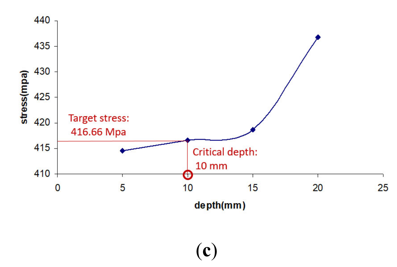
| Run No. | Inputs | Output | |
|---|---|---|---|
| Parameter I | Parameter II | Stress | |
| 1 | A | A | 415.13 |
| 2 | A | B | 417.41 |
| 3 | A | C | 419.63 |
| 4 | B | A | 415.61 |
| 5 | B | B | 419.70 |
| 6 | B | C | 421.83 |
| 7 | C | A | 416.44 |
| 8 | C | B | 418.55 |
| 9 | C | C | 436.9 |
| Crack Type | Critical Dimensions | ||
|---|---|---|---|
| Length (mm) | Depth (mm) | Angle | |
| Environmental crack | 300 | 17 | 0 |
| Environmental crack | 400 | 14 | 0 |
| Crack | 150 | 12 | 45 |
| Crack | 200 | 10 | 45 |
| Longitudinal crack | 300 | 35 | 90 |
| Longitudinal crack | 400 | 33 | 90 |
| Defect Type | Critical Sizes | |
|---|---|---|
| Diameter (mm) | Depth (mm) | |
| Corrosion cavity | 50 | 12 |
| Corrosion cavity | 100 | 11 |
| Corrosion cavity | 150 | 10 |
Publisher’s Note: MDPI stays neutral with regard to jurisdictional claims in published maps and institutional affiliations. |
© 2020 by the authors. Licensee MDPI, Basel, Switzerland. This article is an open access article distributed under the terms and conditions of the Creative Commons Attribution (CC BY) license (http://creativecommons.org/licenses/by/4.0/).
Share and Cite
Omidi Bidgoli, M.; Reza Kashyzadeh, K.; Rahimian Koloor, S.S.; Petru, M. Estimation of Critical Dimensions for the Crack and Pitting Corrosion Defects in the Oil Storage Tank Using Finite Element Method and Taguchi Approach. Metals 2020, 10, 1372. https://doi.org/10.3390/met10101372
Omidi Bidgoli M, Reza Kashyzadeh K, Rahimian Koloor SS, Petru M. Estimation of Critical Dimensions for the Crack and Pitting Corrosion Defects in the Oil Storage Tank Using Finite Element Method and Taguchi Approach. Metals. 2020; 10(10):1372. https://doi.org/10.3390/met10101372
Chicago/Turabian StyleOmidi Bidgoli, Mostafa, Kazem Reza Kashyzadeh, Seyed Saeid Rahimian Koloor, and Michal Petru. 2020. "Estimation of Critical Dimensions for the Crack and Pitting Corrosion Defects in the Oil Storage Tank Using Finite Element Method and Taguchi Approach" Metals 10, no. 10: 1372. https://doi.org/10.3390/met10101372
APA StyleOmidi Bidgoli, M., Reza Kashyzadeh, K., Rahimian Koloor, S. S., & Petru, M. (2020). Estimation of Critical Dimensions for the Crack and Pitting Corrosion Defects in the Oil Storage Tank Using Finite Element Method and Taguchi Approach. Metals, 10(10), 1372. https://doi.org/10.3390/met10101372