Article

Improvement in Weldment of Dissimilar 9% CR Heat-Resistant Steels by Post-Weld Heat Treatment

1
State Key Laboratory of Long-life High Temperature Materials, Dongfang Turbine Co., Ltd., Deyang 618000, China
2
Manufacturing Technology Department, Dongfang Turbine Co., Ltd., Deyang 618000, China
3
College of Materials Science and Engineering, Chongqing University, No. 174, Shazheng Street, Shapingba District, Chongqing 400044, China
*
Authors to whom correspondence should be addressed.
Metals 2020, 10(10), 1321; https://doi.org/10.3390/met10101321
Submission received: 6 September 2020 / Revised: 22 September 2020 / Accepted: 24 September 2020 / Published: 2 October 2020
(This article belongs to the Special Issue Technology of Welding and Joining)

Abstract

:
The effect of the post-weld heat treatment on the microstructures and mechanical properties of the dissimilar joint of G115, a novel developed martensite heat resistant steel, and CB2 steel, currently used in an ultra-super-critical power unit, was investigated. The results indicate that the quenched martensite underwent decomposition and transformation, and the amount of dislocations were sharply decreased in the weld metal after post-weld heat treatment (PWHT). Many nano-scale M23C6 precipitates present in the weldment were distributed on the grain and grain boundary in a dispersed manner with PWHT. The average microhardness of the weldment decreased from about 400 HV to 265–290 HV after PWHT and only a slight decrease in the microhardness of CB2 steel was detected after PWHT at 760 °C. In contrast to the case of the as-received joint, the tensile strength of the joint was improved from 630 MPa to 694 MPa and the fracture location moved from the weld metal to the base metal after PWHT. The fracture surface consisted of a cleavage fracture mode without PWHT, whereas many dimples were observed on the fracture surface with PWHT.

1. Introduction

Heat resistant steels are widely used as structural materials for boilers, main steam pipes, and turbines of power plants [1,2]. In order to improve steam parameters and heat efficiency, researchers have turned their targets to higher-parameter thermal power units above 630 °C for developing high-capacity ultra-super-critical power plants [3]. At present, the upper limit of the operating temperature of the commercial heat-resistant steel is about 600 °C. Beyond the temperatures, problems in the still, such as thermally unstable microstructure, insufficient durability and insufficient environmental corrosion resistance, need to be considered [4]. Thus, the key factor restricting the construction of a 630 ℃ power station is the ability to produce heat-resistant steel in the higher temperature range of 630 °C [5,6].
In this context, many attempts have been made to overcome this limitation. A martensitic heat-resistant steel with a 9Cr-3W-3Co composition system is pivotal to research and development. MARBN (9Cr-3W-3CoVNbBN) [7,8,9], SAVE12AD (9Cr-3W-3CoNdVNbBN) [10], NPM (9Cr-3W-3CoVNbBN) [11], 9Cr3W (9.5Cr-3.1W-3.2CoVNbBN) [12] and G115 (9Cr-2.8W-3CoCuVNbBN) [13,14,15,16] steels have been developed. In recent years, many studies were focused on the structures and mechanical properties of G115 steel [13,14,15,16], which revealed that G115 steel has excellent structural stability and high-temperature creep properties at 630 °C. The endurance strength of G115 steel at 650 °C is 1.5 times that of P92 steel, and its resistance to high-temperature steam oxidation corrosion is better than that of P92 steel [16].
The welding research on heat-resistant steel was mostly concentrated on P91 [17,18] and P92 [19,20] steels. The joints of other steels with a 9Cr-3W-3Co composition system, such as MARBN steel, have also been reported [21,22]. As G115 steel is a newly developed heat-resistant steel, which will be used in the high temperature components; so far researches on the welding of G115 steel were limited. In this study, G115 steel was selected for welding with a heat-resistant steel (CB2), still currently used in the unit. After welding, microstructure similar to that found by casting formed in the weld bead, the heat-affected zone (HAZ) that appears adjacent to the weld line, and residual stress can be produced. To reduce these influences on the joint, post-weld heat treatment (PWHT) was employed. The improvements in the microstructure and mechanical properties of the dissimilar joints of G115 and CB2 steels with PWHT are discussed in detail in this paper.

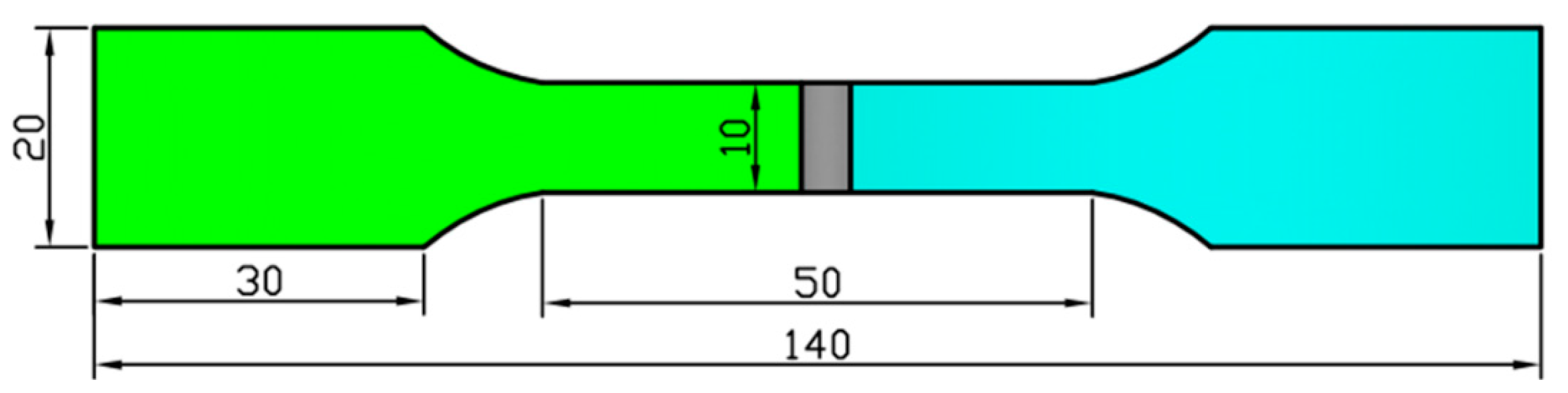
2. Materials and Methods

G115 and CB2 steel blanks, measuring 80 × 70 × 2 mm, were machined from as-received plates and utilized as the base metals. The G115 steel plate with dimensions of 200 × 150 × 40 mm, which was produced by China BaoWu Steel Group Corporation Limited (Shanghai, China), was in the condition of quenching and high temperature tempering. A filler wire with a diameter of 2.4 mm was used and its composition was similar to that of G115 steel. The filler wire was made by Atlantic China Welding Consumables INC (Zigong, China). The chemical composition of the substrates and filler are given in Table 1.
A common welding method, tungsten inert gas (TIG) welding, was used to weld G115 and CB2 steels by a TIG welding machine (YC-300WP5HGN, Panasonnic industrial machinery Co., Ltd., Tangshan, China). Based on the results of previous research, the welding current, the wire feed speed and the welding speed were 130 A, 0.5 m/min and 0.15 m/min, respectively. The post-welding heat treatment was conducted at 700, 730 and 760 °C for 2 h in a resistance heating furnace. The temperature of the solid solution of CB2 steel was about 730 °C.
Specimens for metallographic examination were sectioned from the welded joints. Ground and polished cross sections were etched in a solution (5 g FeCl3 + 15 mL HCl + 80 mL H2O) to observe the joint microstructure. Microstructural observations were conducted using an optical microscope (OM, DM2000X, Chongqing, China) and a scanning electron microscope (SEM, TESCAN VEGA 3 LMH, Brno, Czech Republic). Morphology and precipitates were analyzed by TEM. Microhardness testing was used to determine the hardness profile of the joint region. The testing was carried out using a load of 4.9 N on a hardness tester (MH3N). The hardness testing was performed at a position 1 mm below the surface, and the distance between the hardness points was about 0.25 mm. Tensile tests were conducted by an electronic tensile test machine (AG-X 50KN, Shimadzu, Kyoto, Japan), where the loading rate was 1 mm/min. The tensile testing is shown schematically in Figure 1. Three specimens were tested for each condition. After tensile testing, the fracture surfaces of the samples were observed with SEM.

3. Results and Discussion

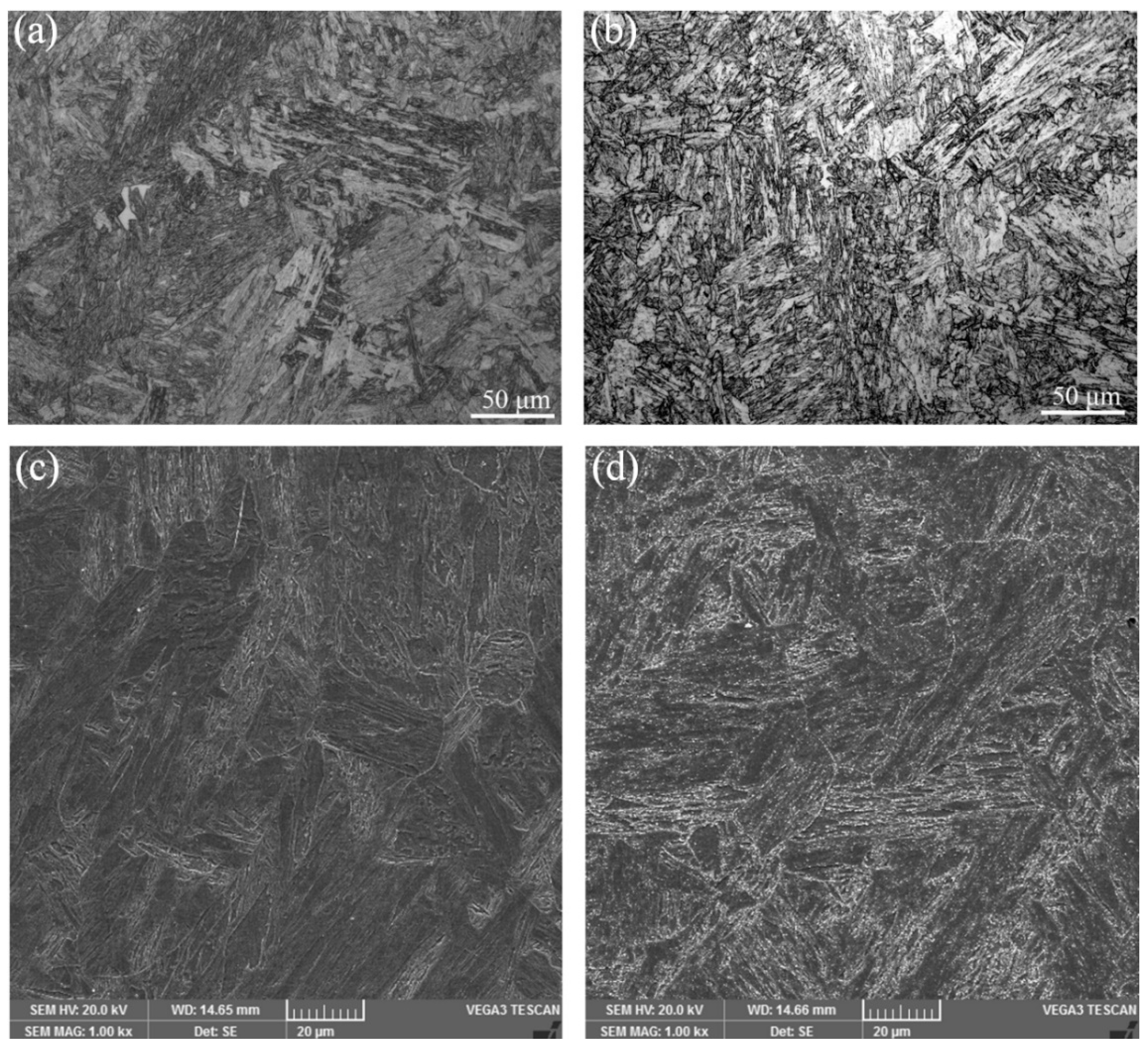
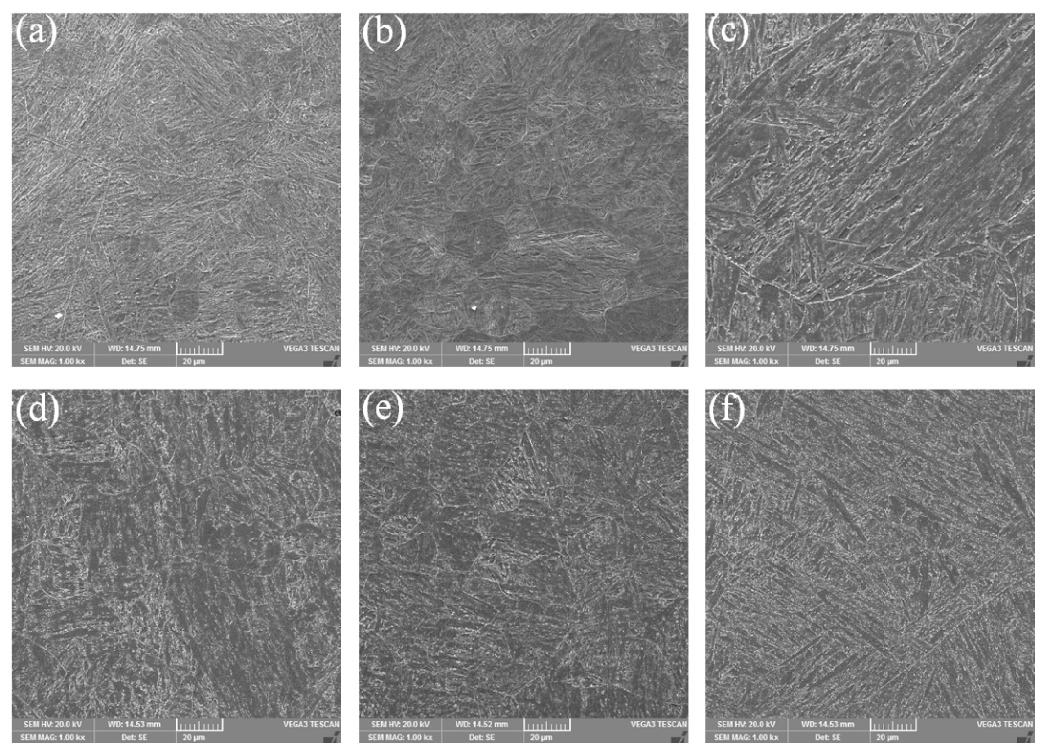
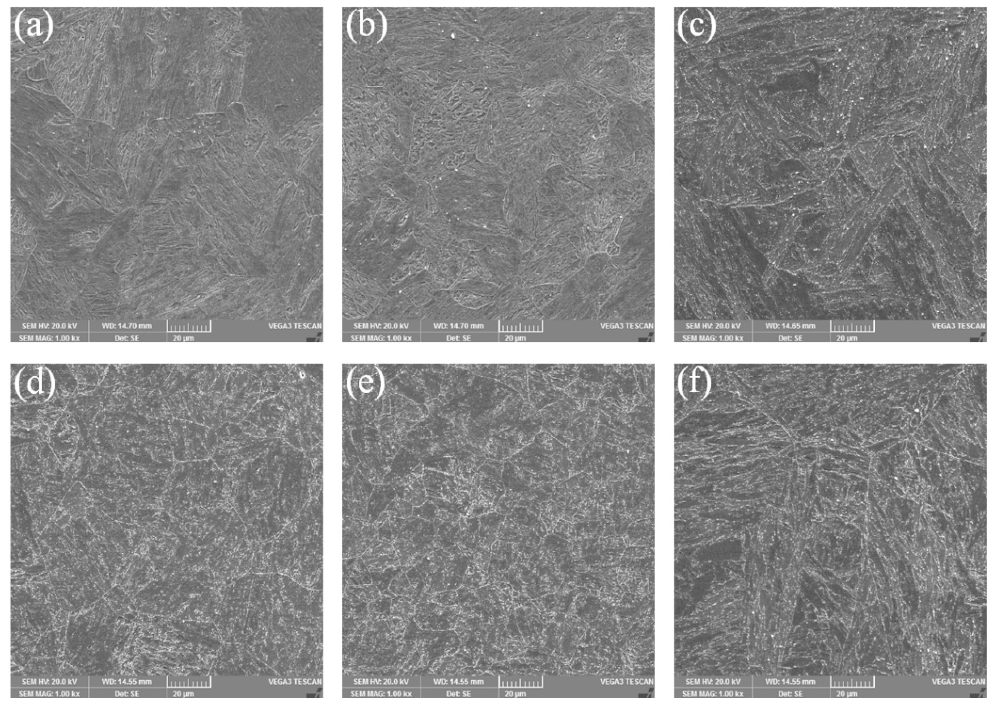
3.1. Microstructure of the Weld Metal

Figure 2 exhibits typical weld metal OM and SEM images of specimens prepared without and with PWHT (post-weld heat treatment) at a temperature of 730 °C after holding for 2 h. Without PWHT, the microstructure of the weld seam was dominated by lath martensite. The boundaries of martensite lath bundles were clearly visible, and the martensite in each lath bundle had relatively uniform directionality. With PWHT, the tempered martensite laths were discontinuous, and the boundaries of the martensite lath bundles became less clear. Fine grain precipitates were found on the martensite laths and the boundaries of the lath bundles; the number of precipitation phases was large and their distribution was dispersed.
Figure 3 and Figure 4 demonstrate the typical SEM images of HAZ (heat-affected zone) and the base metal of CB2 steel and G115 steel. The results in Figure 3a–c and Figure 4a–c are from as-welded joints, whereas the images in Figure 3d–f and Figure 4d–f are from the joints with PWHT at 730 °C for 2 h. The microstructure of CB2 steel and G115 steel is shown in Figure 3c,f and Figure 4c,f. Figure 3a,b, Figure 3d–e, Figure 4a,b and Figure 4d,e show steel that is in the HAZ. The positions for Figure 3a,d and Figure 4a,d were closer to the weld metal than Figure 3b,e and Figure 4b,e, respectively. In contrast with Figure 3b,e and Figure 4b,e, the size of martensite lath bundles shown in Figure 3a,d and Figure 4a,d was relatively larger, due to the higher temperature effect of these areas closer to the weld line. There are a few precipitates in the substrate of G115 steel in the joint without PWHT; that is because the as-received condition of the G115 steel is different from the condition of the CB2 steel. As compared with the as-welded joint, many precipitates were observed in the HAZ for the base metal involving CB2 and G115 steel after PWHT at 730 °C for 2 h.
Figure 5 shows typical TEM (transmission electron microscope) images of the weld metal in the joints produced without PWHT. From Figure 5, the matrix phase of the weldment was martensite, and the width of the martensite lath was approximately several hundred nanometers. The distribution of the lath martensite with a certain length was regular and directional. The quenched martensite was formed by shearing and resulted in a high defect density. A large number of dislocations and dislocation tangles were detected on and between the martensite laths. These dislocations were unevenly distributed, and the dislocation cells of the cellular substructure might be formed in some high-density dislocation regions.
Figure 6 illustrates typical weld metal TEM images of the joints obtained with PWHT at 730 °C for 2 h. From Figure 3, the directionality and length of the martensite laths were clearly reduced and shortened after PWHT, which can be explained by the following three reasons: (1) Firstly, the long laths of quenched martensite are decomposed, owing to the effect of the high temperature. (2) Secondly, some martensite phases undergo recovery and recrystallization processes, and then the equiaxed crystals with low dislocation density are transformed from the lath crystals. (3) Thirdly, sub-grains are formed from remaining dislocations, through multilateralization and then gradually grow up when undergoing higher temperature for an extended long time. The dislocation density was decreased significantly, which can be attributed to the reduction and disappearance of dislocations and dislocation cells in the recovery process during PWHT. The carbides were identified as M23C6 phase by the diffraction patterns. Many carbide particle phases were formed on the grains and grain boundaries. The precipitate size ranged from approximately several nanometers to tens of nanometers, and the size of very few carbides was approximately hundreds of nanometers.

3.2. Microhardness of the Joint

Figure 7 displays the variation of microhardness in the joint region without and with PWHT. For the as-welded joint, the microhardness of the weld metal, whose average value is about 400 HV, is significantly higher than that of the G115 steel and CB2 steel. This might be interpreted in the following four aspects: (1) Firstly, the quenched martensite transformed by rapid cooling has higher microhardness, which results in transformation hardening in the weld zone. (2) Secondly, there are no carbide precipitates in the quenched martensite matrix, and almost all carbon atoms are dissolved into the matrix in a supersaturated form. This can lead to solid solution hardening in the weld zone. (3) Thirdly, the residual stress produced by welding and stored in the weldment makes the measured microhardness values higher. (4) Finally, a large number of dislocations (Figure 5b) are produced in the rapid cooling process and during the quenched martensite formation. This might cause dislocation hardening in the weld seam. The microhardness values of the base metal areas were higher than those of the center area, because the above-mentioned four hardening effects are greater at the faster cooling rate. The microhardness of the G115 steel was similar to that of the CB2 steel, and its value was approximately 250 HV. By comparing the two cases of without and with PWHT, an obvious change in the microhardness profile is that the microhardness of the weld seam was sharply reduced to 265–290 HV after PWHT. The transformation of tempered martensite from quenched martensite, the reduction of the solid solution carbon content in martensite, the elimination of the remaining stress and the decrease and disappearance of dislocation density during PWHT can make the microhardness of the weldment notably low. As the PWHT temperature increased, the microhardness of the G115 steel side did not change significantly, which indicates that the G115 steel has good high temperature stability. However, the microhardness of the weldment and CB2 steel side was slightly reduced especially at 760 °C. The further coarsening of grains at the higher temperature may be responsible for the decrease in microhardness.

3.3. Tensile Strength of the Joint

Figure 8 presents the tensile strengths of the joints without and with PWHT. The tensile strength of the joint without PWHT was about 630 MPa, and the fracture during tensile testing was located in the weld seam. Due to the large amount of fine carbides with dispersed distribution (Figure 6), the tensile strength values of the joints that underwent PWHT were notedly larger than those without PWHT, and the failure during tensile testing took place in the base metal of CB2, which indicates that the thermal strength of CB2 is lower than that of G115. As the PWHT temperature increased from 700 to 730 °C, the joint strength improved markedly, whereas the joint strength clearly decreased by further increasing the PWHT temperature from 730 to 760 °C. The reduction in the properties including microhardness and tensile strength of CB2 steel at 760 °C might be because the temperature was higher than the solid solution temperature of CB2 steel. The maximum strength of the joint that was reached was 694 MPa at the PWHT temperature of 730 °C, which was approximately 94 % of the tensile strength of the base metal (Table 2).
Table 3 shows the yield strength and elongation to failure of the welded joints without and with PWHT. The yield strength values of the joints with PWHT are much larger than those without PWHT. The yield stress exhibits a change that firstly increases and then decreases as the temperature of PWHT enhances, which was similar to the change in the tensile strength. The maximum yield strength obtained with PWHT at 730 °C was higher than that of the joint without PWHT by about 159 MPa. The ductility of the joint increased significantly after PWHT, and the elongation values of the joints with PWHT were an order of magnitude larger than those without PWHT.

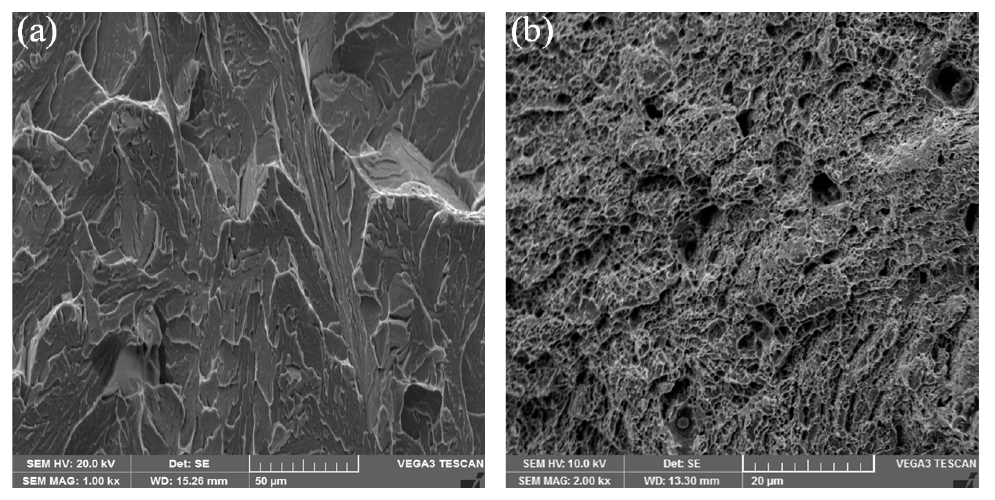
3.4. Fracture Characteristics

Figure 9 represents the fracture surface images of the joints without and with PWHT of 730 °C. The fracture of the as-welded joint occurred in the weldment; the failed surface contained cleavage fracture characteristics and it is considered to be a mainly brittle fracture. In all cases investigated for PWHT, the weld seam was strengthened and CB2 steel became a weak part, causing fractures that occurred in the CB2 side. The post fracture microstructures of the joints were similar and there were many dimples on the fracture surface. The results indicate that the PWHT process improved the microstructure and mechanical properties of the weldment, thereby avoiding brittle fracture at the weld.

4. Conclusions

In this paper, the microstructures and mechanical properties of the weldment between G115 and CB2 steels without and with PWHT were studied. The related conclusions can be drawn as follows:
(1)
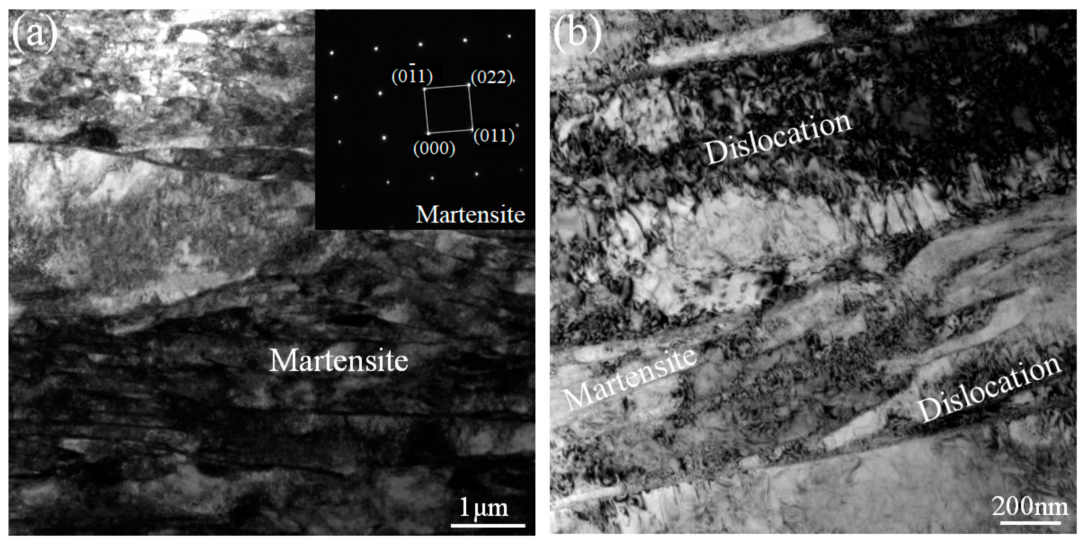
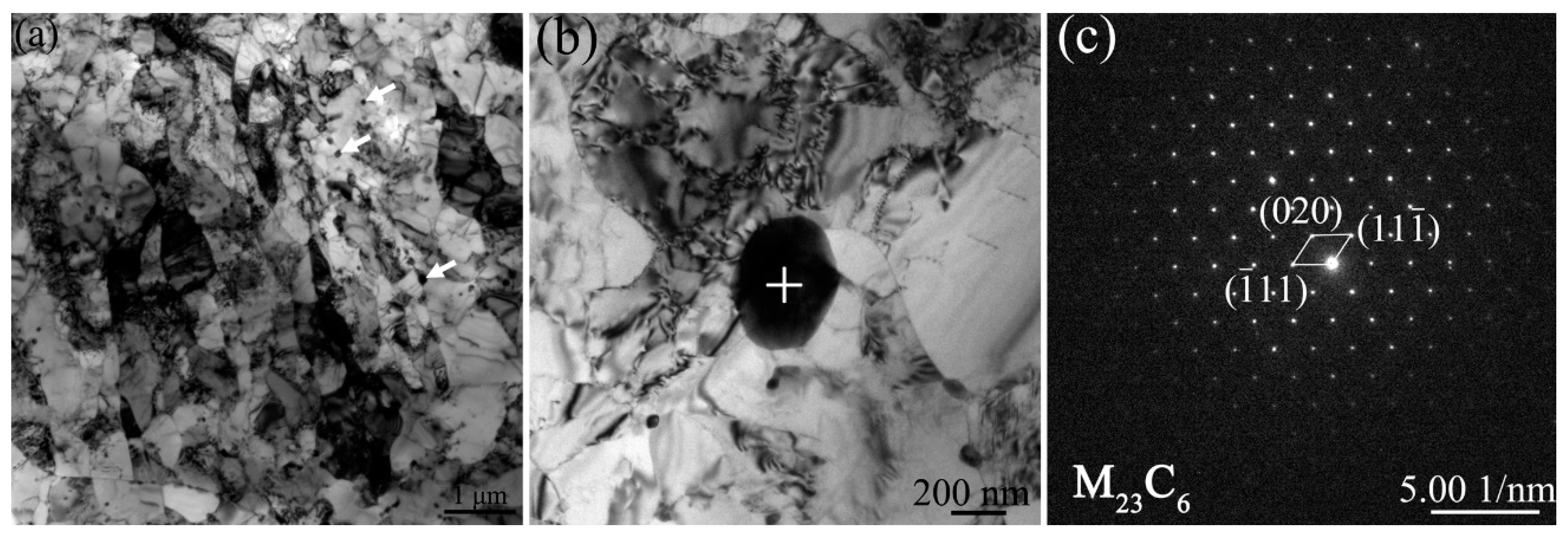
Without PWHT, the weld seam was mainly composed of the quenched martensite with a lath thickness of approximately several hundred nanometers Many dislocations and dislocation tangles were found on and between the martensite laths. With PWHT, the tempered martensite was transformed from the quenched martensite and the number of dislocations was drastically reduced. In addition, M23C6 secondary-phases with the size of approximately several nanometers to tens of nanometers were dispersedly distributed on the grains and grain boundaries.
(2)
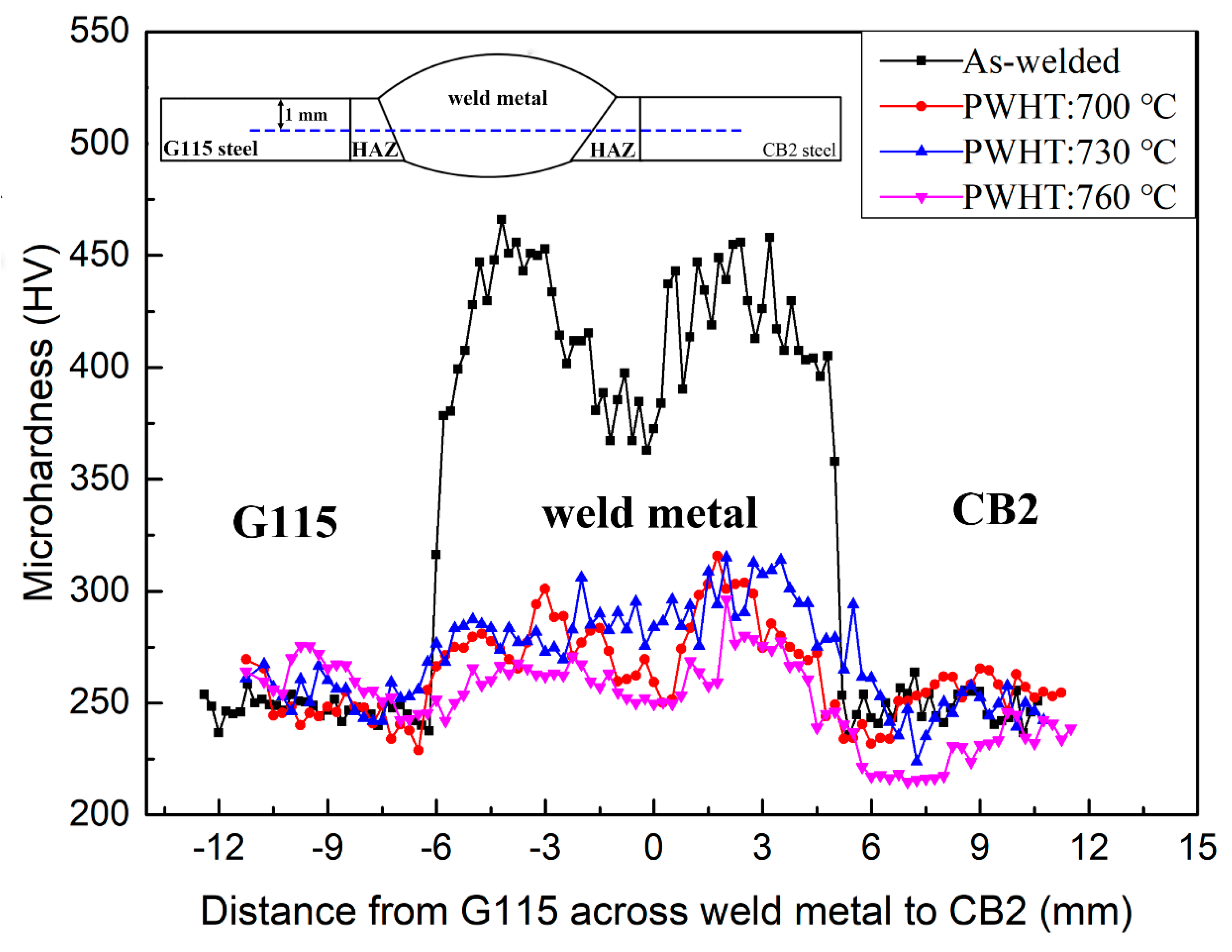
Without PWHT, the average microhardness of the weldment (~400 HV) was evidently larger than that of the G115 steel and CB2 steel (~250 HV). With PWHT, the microhardness of the weldment decreased to 265–290 HV and the microhardness of CB2 steel was slightly reduced at 760 °C for PWHT.
(3)
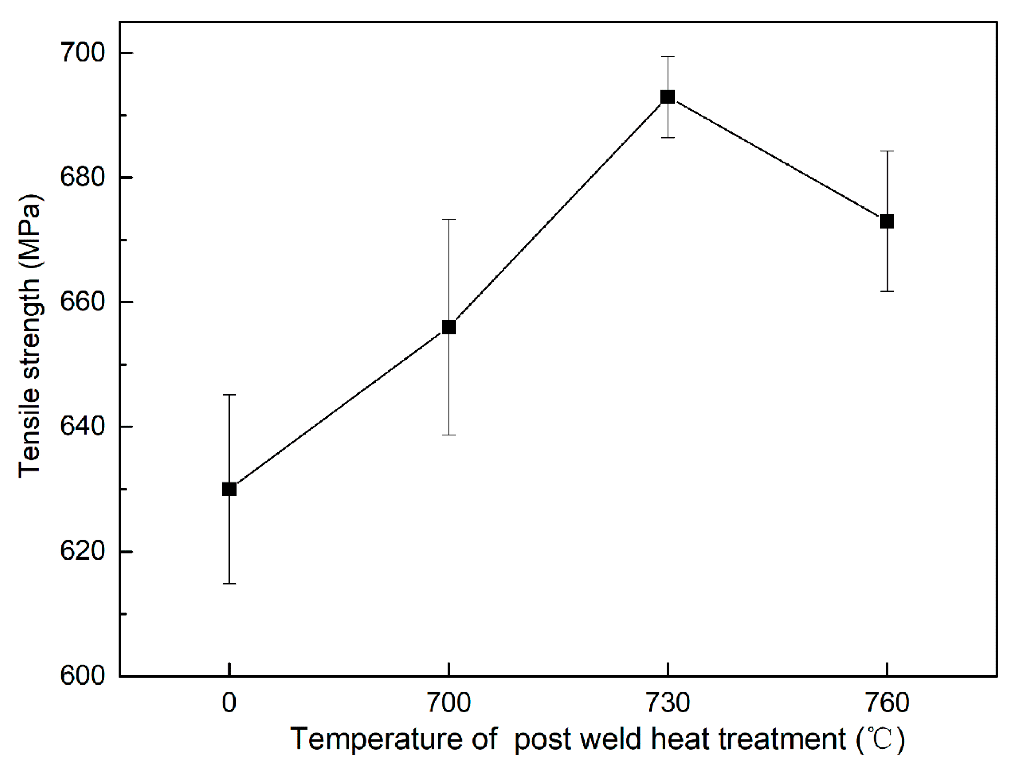
Without PWHT, the tensile strength of the joint was about 630 MPa, and the fracture with mainly cleavage fracture characteristics occurred in the weld seam. With PWHT, the joint strength increased significantly and reached up to a maximum value (694 MPa) at 730 °C, which might result from many dispersed precipitates, and the fracture with many dimples was located in the base metal of CB2 steel.

Author Contributions

J.X. (Jiankun Xiong), X.Y., J.Y., L.Y., and J.X. (Jian Xu) formulated the original problem, designed the study, developed the methodology, and wrote the manuscript. J.X. (Jiankun Xiong), T.L., X.Y., G.M. and J.X. (Jian Xu) performed the welding, testing, characterization and collected data. J.X. (Jiankun Xiong) and G.M. controlled the materials selection. J.X. (Jiankun Xiong) and X.Y. provided guidance and interpretation of data. All authors have read and agreed to the published version of the manuscript.

Funding

This work was financially supported by the Sichuan Deyang Open University-City Cooperative Technology Research and Development Project (Project No.: 2018CKJ004) and the Sichuan Deyang Industry-University-Research Cooperation Technology R&D Project (Project No.: 2019CK094). This research was also supported by the fund of Sate Key Laboratory of Long-life High Temperature Materials (Project No.: DTCC28EE190934).

Conflicts of Interest

The authors declare no conflict of interest.

References

  1. Fedoseeva, A.; Dudova, N.; Kaibyshev, R.; Belyakov, A. Effect of tungsten on creep behavior of 9%Cr–3%Co martensitic steels. Metals 2017, 7, 573. [Google Scholar] [CrossRef] [Green Version]
  2. Kaybyshev, R.O.; Skorobogatykh, V.N.; Shchenkova, I.A. New martensitic steels for fossil power plant: Creep resistance. Phys. Met. Metallogr. 2010, 109, 186–200. [Google Scholar] [CrossRef]
  3. Wang, X.; Wang, X.; Luo, B.; Hu, X.; Yuan, T. Creep degradation assessment in 9%Cr heat-resistant steel welded joints using ultrasonic methods. Results Phys. 2019, 12, 307–320. [Google Scholar] [CrossRef]
  4. Zinkle, S.J.; Was, G.S. Materials challenges in nuclear energy. Acta Mater. 2013, 61, 735–758. [Google Scholar] [CrossRef]
  5. Rojas, D.; Garcia, J.; Prat, O.; Sauthoff, G.; Kaysser-Pyzalla, A.R. 9%Cr heat resistant steels: Alloy design, microstructure evolution and creep response at 650 °C. Mater. Sci. Eng. A 2011, 528, 5164–5176. [Google Scholar] [CrossRef]
  6. Wang, H.; Yan, W.; Zwaag, S.V.; Shi, Q.; Wang, W.; Yang, K.; Shan, Y. On the 650 ℃ thermostability of 9e12Cr heat resistant steels containing different precipitates. Acta Mater. 2017, 134, 143–154. [Google Scholar] [CrossRef]
  7. Abe, F. New Martensitic Steels. In Materials for Ultra-Supercritical and Advanced Untra-Supercritical Power Plants; Gianfrancesco, A.D., Ed.; Woodhead Publishing: Cambrige, UK, 2017; pp. 323–374. [Google Scholar]
  8. Abe, F. Development of Creep-Resistant Steels and Alloys for Use in Power Plants. In Structural Alloys in Power Plants; Shirzadi, A., Jackson, S., Eds.; Woodhead Publishing: Cambridge, UK, 2014; pp. 250–293. [Google Scholar]
  9. Abstossa, K.G.; Schmigallab, S.; Schultzeb, S.; Mayr, P. Microstructural changes during creep and aging of a heat resistant MARBN steel and their effect on the electrochemical behaviour. Mater. Sci. Eng. A 2019, 743, 233–242. [Google Scholar] [CrossRef]
  10. Iseda, A.; Yoshizawa, M.; Okada, H.; Hamaguchi, T.; Hirata, H.; Joutoku, K.; Ono, T.; Tanaka, K. Development of 9Cr ferritic steel tube and pipe SAVE12AD for advanced power boilers. Therm. Nucl. Power Gener. Conv. Collect. Works 2016, 12, 49–55. [Google Scholar]
  11. Hollner, S.; Piozin, E.; Mayr, P.; Caës, C.; Tournié, I.; Pineau, A.; Fournier, B. Characterization of a boron alloyed 9Cr3W3CoVNbBN steel and further improvement of its high-temperature mechanical properties by thermomechanical treatments. J. Nucl. Mater. 2013, 441, 15–23. [Google Scholar] [CrossRef]
  12. Fedoseeva, A.; Dudova, N.; Kaibyshev, R. Creep behavior and microstructure of a 9Cr–3Co–3W martensitic steel. J. Mater. Sci. 2017, 52, 2974–2988. [Google Scholar] [CrossRef]
  13. Xiao, B.; Xu, L.; Zhao, L.; Jing, H.; Han, Y.; Zhang, Y. Creep properties, creep deformation behavior, and microstructural evolution of 9Cr-3W-3Co-1CuVNbB martensite ferritic steel. Mater. Sci. Eng. A 2018, 711, 434–447. [Google Scholar] [CrossRef]
  14. Liu, Z.; Liu, Z.; Wang, X.; Chen, Z. Investigation of the microstructure and strength in G115 steel with the different concentration of tungsten during creep test. Mater. Charact. 2019, 149, 95–104. [Google Scholar] [CrossRef]
  15. Xiao, B.; Xu, L.; Cayronc, C.; Xue, J.; Sha, G.; Logé, R. Solute-dislocation interactions and creep-enhanced Cu precipitation in a novel ferritic-martensitic steel. Acta Mater. 2020, 195, 199–208. [Google Scholar] [CrossRef]
  16. Yu, Y.; Liu, Z.; Zhang, C.; Fan, Z.; Chen, Z.; Bao, H.; Chen, H.; Yang, Z. Correlation of creep fracture lifetime with microstructure evolution and cavity behaviors in G115 martensitic heat-resistant steel. Mater. Sci. Eng. A 2020, 788, 139468. [Google Scholar] [CrossRef]
  17. Silva, F.J.G.; Pinho, A.P.; Pereira, A.B.; Paiva, O.C. Evaluation of welded joints in P91 steel under different heat-treatment conditions. Metals 2020, 10, 99. [Google Scholar] [CrossRef] [Green Version]
  18. Wang, Y.; Li, L.; Kannan, R. Transition from type IV to type I cracking in heat-treated grade 91 steel weldments. Mater. Sci. Eng. A 2018, 714, 1–13. [Google Scholar] [CrossRef]
  19. Wang, X.; Pan, Q.; Liu, Z.; Zeng, H.; Tao, Y. Creep rupture behaviour of P92 steel weldment. Eng. Fail. Anal. 2011, 18, 186–191. [Google Scholar]
  20. Sklenička, V.; Kuchařová, K.; Svobodová, M.; Kvapilová, M.; Král, P.; Horváth, L. Creep properties in similar weld joint of a thick-walled P92 steel pipe. Mater. Charact. 2016, 119, 1–12. [Google Scholar] [CrossRef]
  21. Mayr, P.; Martín, F.M.; Albu, M.; Cerjak, H. Correlation of creep strength and microstructural evolution of a boron alloyed 9Cr3W3CoVNb steel in as-received and welded condition. Mater. High Temp. 2014, 27, 67–72. [Google Scholar] [CrossRef]
  22. Matsunaga, T.; Hongo, H.; Tabuchi, M.; Sahara, R. Suppression of grain refinement in heat-affected zone of 9Cr-3W-3Co-VNb steels. Mater. Sci. Eng. A 2016, 655, 168–174. [Google Scholar] [CrossRef]
Figure 1. The schematic drawing for tensile testing (mm).
Metals 10 01321 g001
Figure 2. Optical microscope (OM) and scanning electron microscope (SEM) images of typical weld metal specimens: (a), (c) without post-weld heat treatment (PWHT); and (b,d) with PWHT at 730 °C for 2 h.
Metals 10 01321 g002
Figure 3. Typical SEM images of the heat-affected zone (HAZ) (a,b), (d,e) and base metal (c), (f) of CB2 steel: (a)–(c) without PWHT and (d)–(f) with PWHT at 730 °C for 2 h.
Metals 10 01321 g003
Figure 4. Typical SEM images of HAZ (a,b), (d,e) and base metal (c), (f) of G115 steel: (a)–(c) without PWHT and (d)–(f) with PWHT at 730 °C for 2 h.
Metals 10 01321 g004
Figure 5. Typical weld metal TEM analysis of the joints produced without PWHT: (a) TEM images and diffraction patterns of martensite, and (b) dislocation.
Metals 10 01321 g005
Figure 6. Typical weld metal TEM analysis of the joints obtained with PWHT at 730 °C for 2 h: (a) TEM images, (b) precipitates images, and (c) diffraction patterns of precipitate. The white arrows highlight the precipitates.
Metals 10 01321 g006
Figure 7. The microhardness profiles of the joint of G115 steel and CB2 steel without and with PWHT.
Metals 10 01321 g007
Figure 8. Tensile strengths of the joints of G115 steel and CB2 steel without and with PWHT.
Metals 10 01321 g008
Figure 9. Typical fracture surface SEM images of the joints: (a) without PWHT and (b) with PWHT, at 730 °C for 2h.
Metals 10 01321 g009
Table 1. The chemical composition of the base metals and filler wire (wt.%).
MetalsCCrWCoMoCuMnSiNiVNbNBFe
G1150.088.82.843.0-1.00.50.3-0.20.060.0080.014Bal.
CB20.119.18-0.981.47-0.690.30.330.20.060.020.009Bal.
Filler0.0888.952.83.01-0.940.350.07-0.220.0080.00960.009Bal.
Table 2. Elongation, yield strength and tensile strength of the base metals.
As-Received G115As-Received CB2G115 at 730 °C for 2 hCB2 at 730 °C for 2 h
Elongation (%)8.926.1410.67.79
Yield strength (MPa)641623621614
Tensile strength (MPa)749746745740
Table 3. Elongation and yield strength of the welded joints without and with PWHT.
As-Weld JointPWHT at 700 °C for 2 hPWHT at 730 °C for 2 hPWHT at 760 °C for 2 h
Elongation (%)0.586.666.697.12
Yield strength (MPa)410547569539

