Article

Crash Characteristics of Partially Quenched Curved Products by Three-Dimensional Hot Bending and Direct Quench

by
Atsushi Tomizawa
1,*,
Sanny Soedjatmiko Hartanto
2,
Kazuo Uematsu
3 and
Naoaki Shimada
4
1
Faculty of Production Systems Engineering and Sciences, Komatsu Univercity, Nu 1-3 Shichomachi, Komatsu, Ishikawa 923-8511, Japan
2
Department of Mechanical Systems Engineering, Okinawa National College of Technology, 905 Henoko, Nago-shi, Okinawa 905-2192, Japan
3
Steel Research Laboratories, Nippon Steel Corporation, 1-8 Fuso-cho, Amagasaki, Hyogo 660-0891, Japan
4
Steel Research Laboratories, Nippon Steel Corporation, 20-1 Shintomi, Futtsu, Chiba 293-0011, Japan
*
Author to whom correspondence should be addressed.
Metals 2020, 10(10), 1322; https://doi.org/10.3390/met10101322
Submission received: 18 August 2020 / Revised: 28 September 2020 / Accepted: 30 September 2020 / Published: 2 October 2020
(This article belongs to the Special Issue Latest Hydroforming Technology of Metallic Tubes and Sheets)

Abstract

:
Recently, improvement of hybrid and electric vehicle technologies, equipped with batteries, continues to solve energy and environmental problems. Lighter weight and crash safety are required in these vehicles body. In order to meet these requirements, three-dimensional hot bending and direct quench (3DQ) technology, which enables to form hollow tubular automotive parts with a tensile strength of 1470 MPa or over, has been developed. In addition, this technology enables to produce partially quenched automotive parts. In this study, the crash characteristics of 3DQ partially quenched products were investigated as the fundamental research of the design for improving the energy absorption. Main results are as follows: (1) for partially quenched straight products in axial crash test, buckling that occurs at nonquenched portion can be controlled; (2) for the nonquenched conventional and overall-quenched curved products, buckling occurs at the bent portion at the initial stage in axial crash tests, and its energy absorption is low; (3) by optimizing partially quench conditions, buckling occurrence can be controlled; and (4) In this study, the largest energy absorption was obtained from the partially quenched curved product, which was 84.6% larger than the energy absorption of the conventional nonquenched bent product in crash test.

1. Introduction

Recently, improvement of hybrid and electric vehicle technologies, equipped with batteries, continues to solve energy and environmental problems. Lighter weight and crash safety are required in the vehicles’ bodies [1]. In order to satisfy these requirements, it has been promoted to apply ultrahigh tensile steel [2]. In the case of sheet metal, application of hot stamping has been promoted to achieve over 1500 MPa tensile strength [3,4]. However, assembling closed-sectional-shaped automotive parts from sheet metal requires spot welding of two or more parts. Therefore, flange for spot welding is indispensable. So, it is difficult to reduce the weight of the components. In addition, ideal rigidity cannot be obtained because the spot welds are intermitted. On the other hand, hydroforming technology has been developed to manufacture high-rigidity hollow components from steel tube. However, generally hydroforming cannot form over 980 MPa strength tubes, and manufacturing facility required for it is large and expensive [5,6]. In addition, as electrification and autonomous automobiles progresses, it is expected that newcomers of automotive manufacturer will increase, and they will demand more compact and low-cost manufacturing facility to depress initial investment cost. Resin body car prototype using 3D printer as the low-cost manufacturing facility even exists [7], but it is uncertain whether the crash performance is sufficient. Thus, the technology that can manufacture more high-strength tubular components with compact and low-cost facility has been desired. Therefore, three-dimensional hot bending and direct quench (3DQ) technology has been developed. 3DQ is a consecutive forming process, which allows bending and quenching at the same time. This technology enables to form hollow tubular structure components of a vehicle bodies with ultrahigh tensile strength and three-dimensional shapes using steel tube. The 3DQ technology is an innovative method, and the method makes it possible to fully enjoy the advantage of steel to manufacture high-strength automotive structural parts at lower costs with excellent recyclability, compared with other materials such as carbon fiber reinforced plastics (CFRP). In addition, 3DQ facility is more compact and low cost than hot press and hydroforming machine. In this study, the crash characteristics of partially quenched curved products by 3DQ and the suitable design are discussed for improving the energy absorption.

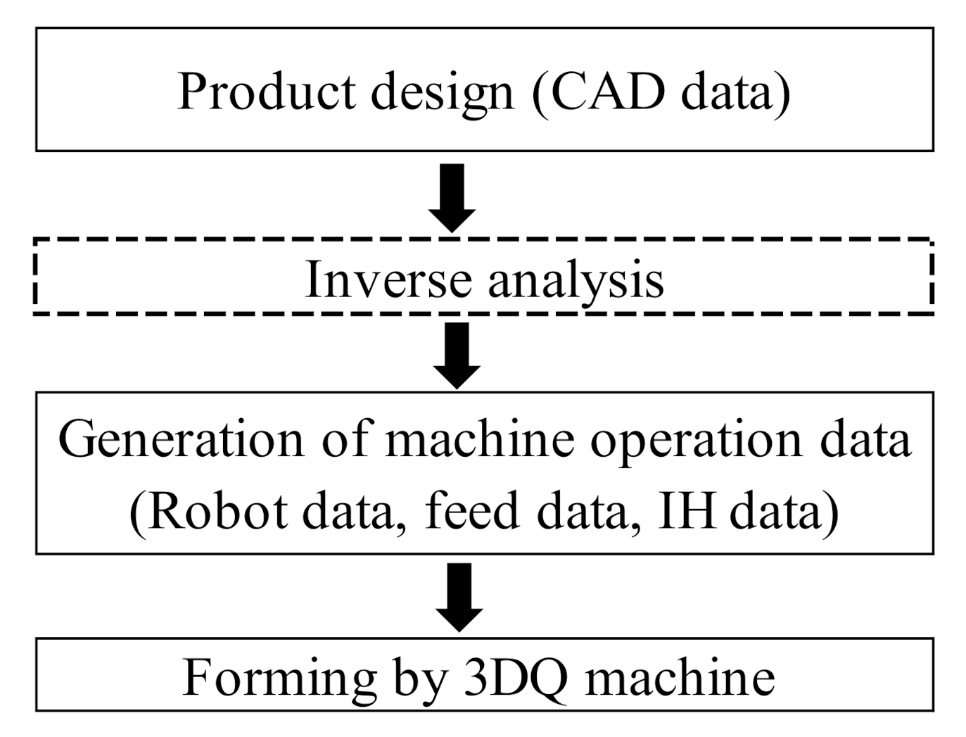
2. Outline of 3DQ Technology

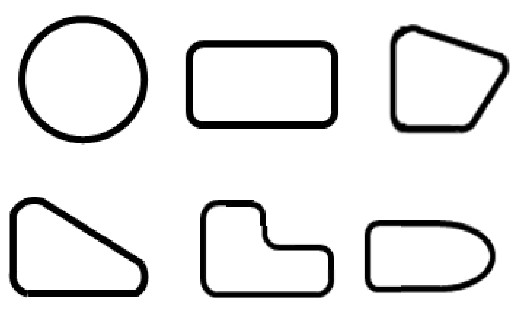
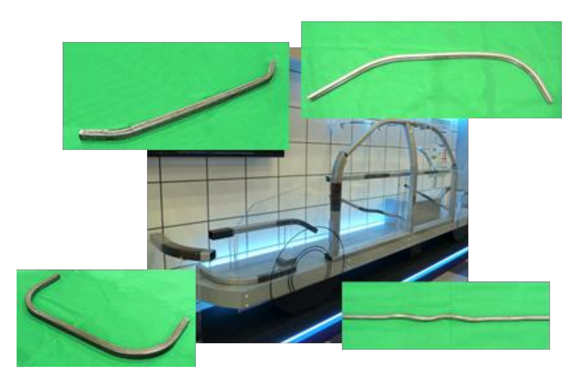
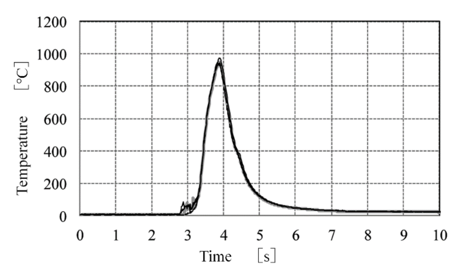
2.1. Features of 3DQ Technology

Figure 1 shows the developed 3DQ machine. The main components of the 3DQ machine are axial feeding device, support guides or rolls, induction heater (IH), water cooling device, and bending robot. First, by inverse analysis from the three-dimensional product shape data, 3DQ operation data are determined (Figure 2). The straight tube is fed supported by the support guides or rolls. As shown in Figure 3, the straight tubes with various cross-sections, such as round, square, and odd-shaped, are available. Then, this tube is heated by the IH rapidly. The heat temperature is more than Ac3 transformation point. After heating, the tube is cooled to room temperature by water cooling device for quenching. At the same time, the tube is bent by robot. The deformation is concentrated in this narrow heating potion. By this process consecutively, the products which have complex three-dimensional bent shape and ultrahigh tensile strength are obtained (Figure 4).
The 3DQ technology has achieved the following characteristics: [8,9,10,11,12]
  • Product tensile strength of 1470 MPa.
  • High shape fixability results in high forming precision.
  • Low residual stress.
  • Low die cost (die less forming).
  • No concern of delayed fracture.
In addition, it is possible to quenched products partially using the IH control.

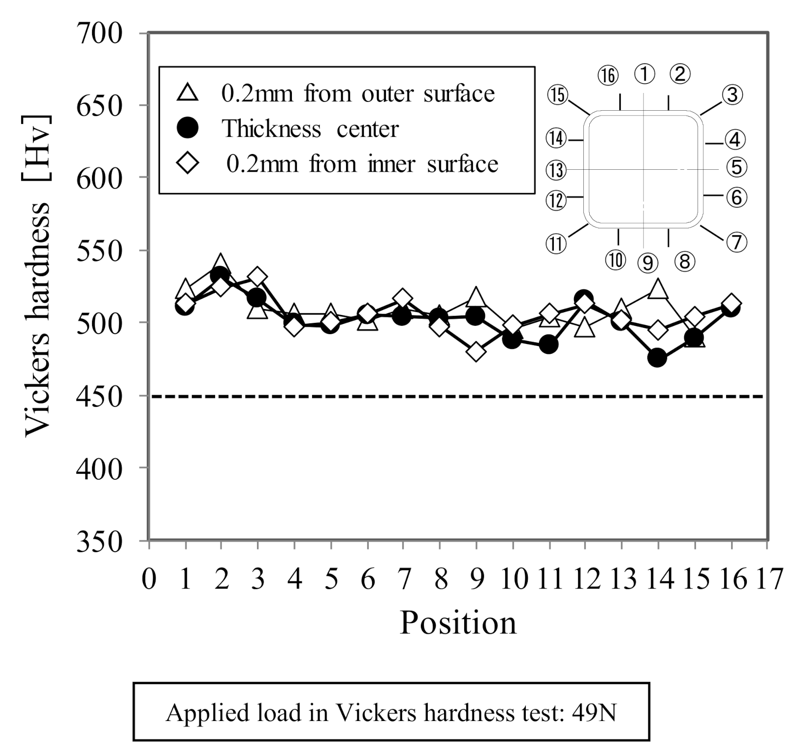
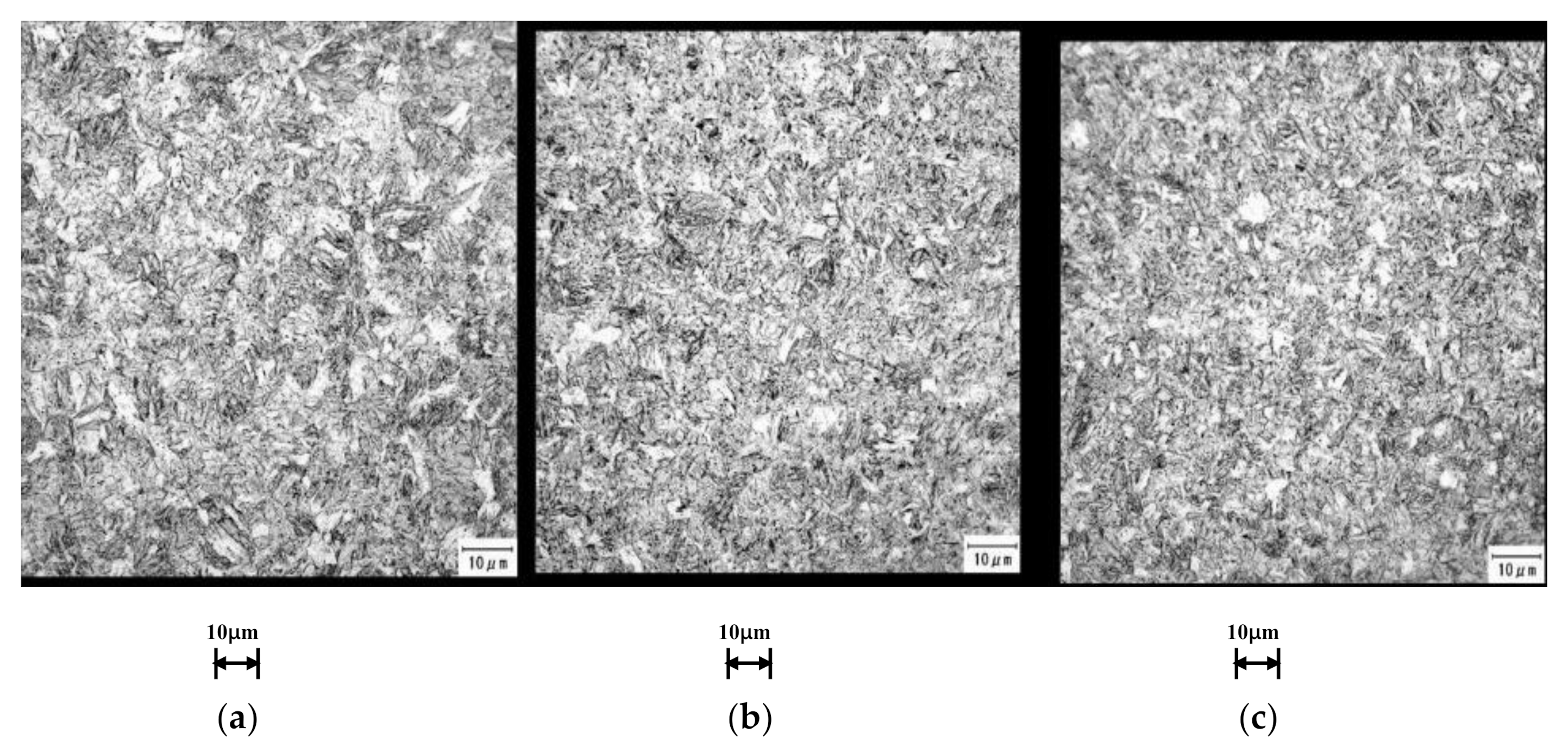
2.2. Properties of 3DQ Products

In this study, the experiments were carried out using the 3DQ machine as shown in Table 1. In the experiment, electric welded steel tubes with a rectangular cross-section were used. Table 2 shows the chemical composition of the test tubes. Figure 5 shows an example of the temperature change during the 3DQ forming process of a square hollow section. It was measured with thermocouples on the internal surface of the material, which was fed at a rate of 80 mm/s. Here, the material was quickly heated to above the Ac3 temperature by the high-frequency heating coil, and then rapidly water-cooled to room temperature.
Figure 6 shows the hardness distribution of the product by the 3DQ machine. Vickers hardness of 450 HV, which is equivalent to tensile strength of 1470 MPa, is obtained in all portions of the product, and the microstructure of the product became uniform martensitic structure, as shown in Figure 7.

3. Crash Characteristics of Partially Quenched Curved Product

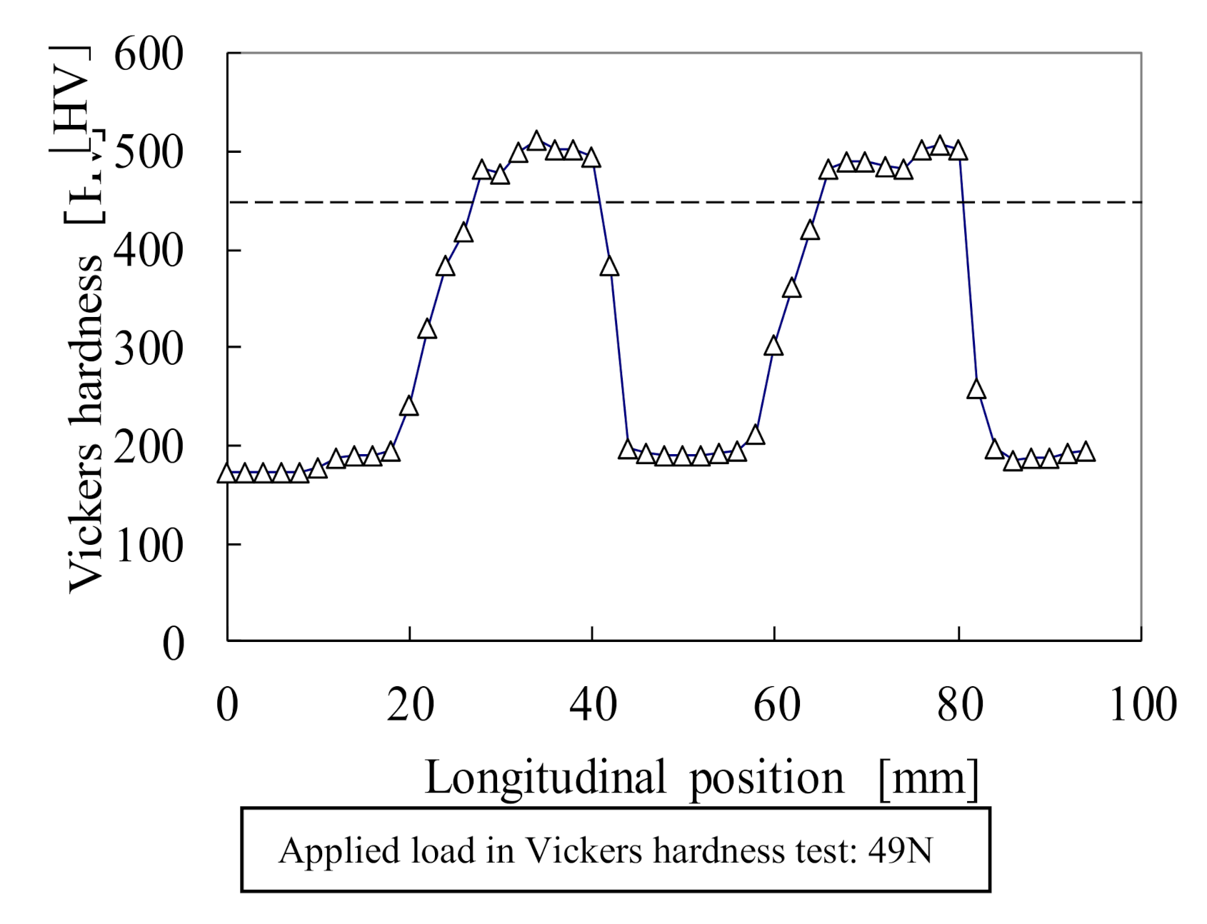
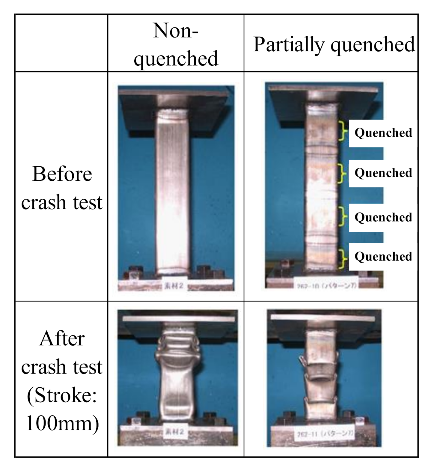
3.1. Deformation Behavior of the Partially Quenched Straight Product

Partial quenching by 3DQ allows strengthening of only the areas of an automobile component that need high-tensile strength. To clarify the deformation behavior of the partially quenched straight product by 3DQ, the axial crash tests were carried out as shown in Table 3 [13]. In the crash test, the load is measured by the load cell. The stroke signal was measured by a laser displacement meter. Hence, the load-stroke diagram is obtained by synchronizing these signals. Figure 8 shows longitudinal hardness distribution of the partially quenched straight product in part of this test tube. Figure 9 shows the results of the axial crash test of the nonquenched and the partially quenched specimens. The nonquenched product deforms sequentially from top of the specimen, whereas the portion which is not quenched deformed preferentially in the partially quenched specimen. In other words, it is suggested that the buckling mode can be controlled by partial quenching. Figure 10 shows the energy absorption of the specimen in this test. For the straight product, the energy absorption of the partially quenched product is a little larger than that of the nonquenched product or in the same level, because the deformation occurs in the nonquenched area.

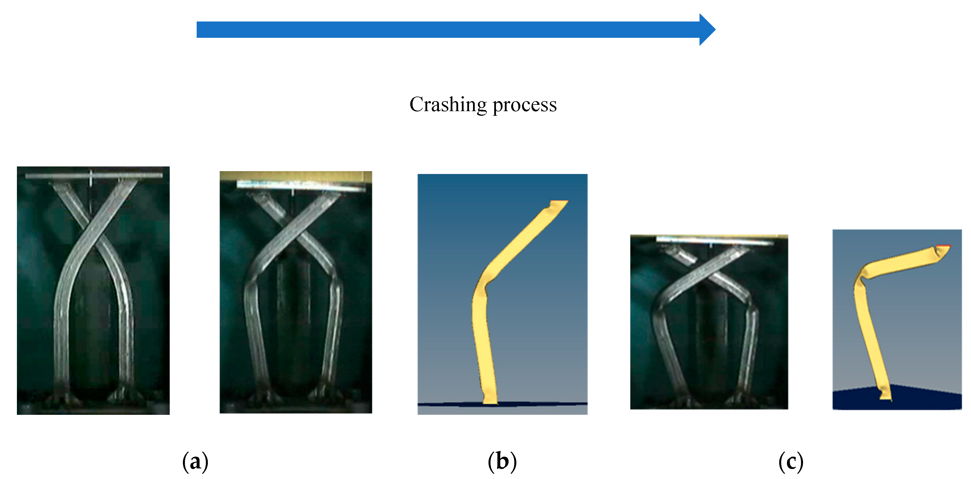
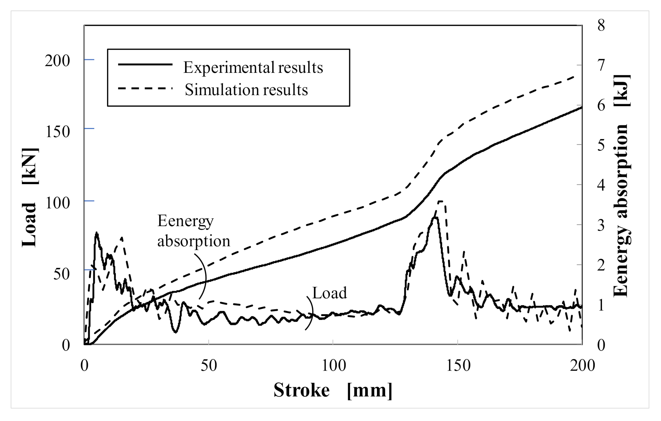
3.2. Deformation Behavior of Partially Quenched Curved Product

The shapes of automotive parts are generally curved. To investigate the effects of some major factors on axial crash behavior of partially quenched curved products by 3DQ, the finite element analysis has been conducted with RADIOSS 13.0 (Altair Engineering, Inc., Troy, MI, USA) using the dynamic explicit method. Table 4 shows the analytical conditions. During the plastic deformation, the material expressed the strengthening phenomenon, so called work hardening, where the stress of material increases exponentially to the strain as shown in Equation (1). In this calculation model, the transition region of hardness, as shown in Figure 8, was not considered.
σ = a + b·εn.
Figure 11 shows the example of the curved product shapes in the crash test: (a) the overall-quenched product and (b) the partially quenched product. In this simulation, the bending radius and its quenched area were varied to investigate the crash characteristics of the curved design products.
In the finite element method (FEM) model, the top of the products is restricted from translation of both X and Y axes and rotation of Z axis, and is deformed by a rigid wall as shown in Table 5. Under the consideration of the symmetry of the test product, half analytical model is applied to the simulation. The bottom of the product is restricted from both displacement and rotation of all axes. Meshing size is 2.0 mm × 2.0 mm.
The initial product shapes are shown in Figure 11a,b. In the crush test, two 3DQ curved products are used as shown in Figure 12a and top and bottom plates are welded to these curved products. The crash behavior of overall-quenched product is shown in Figure 12. The buckling occurs at the bending section during the initial stage. Figure 13 shows the crash behavior of partially quenched product. The first buckling occurs at the nonquenched upper part of the product and the second buckling occurs at the nonquenched lower part of the product. In this study, the simulation results are in good agreement with the experimental results. Figure 14 and Figure 15 show the relationship between load and stroke of overall-quenched product and partially quenched product in crash test for both experimental and simulation results. Both graphs are in good agreement practically. These absolute values difference seems to be due to difference between their boundary conditions. Since the energy absorption represents the area of stroke-load diagram in crash test, there is a possibility of improving crash performance by applying partially quenched products by 3DQ, as seen in Figure 14 and Figure 15.

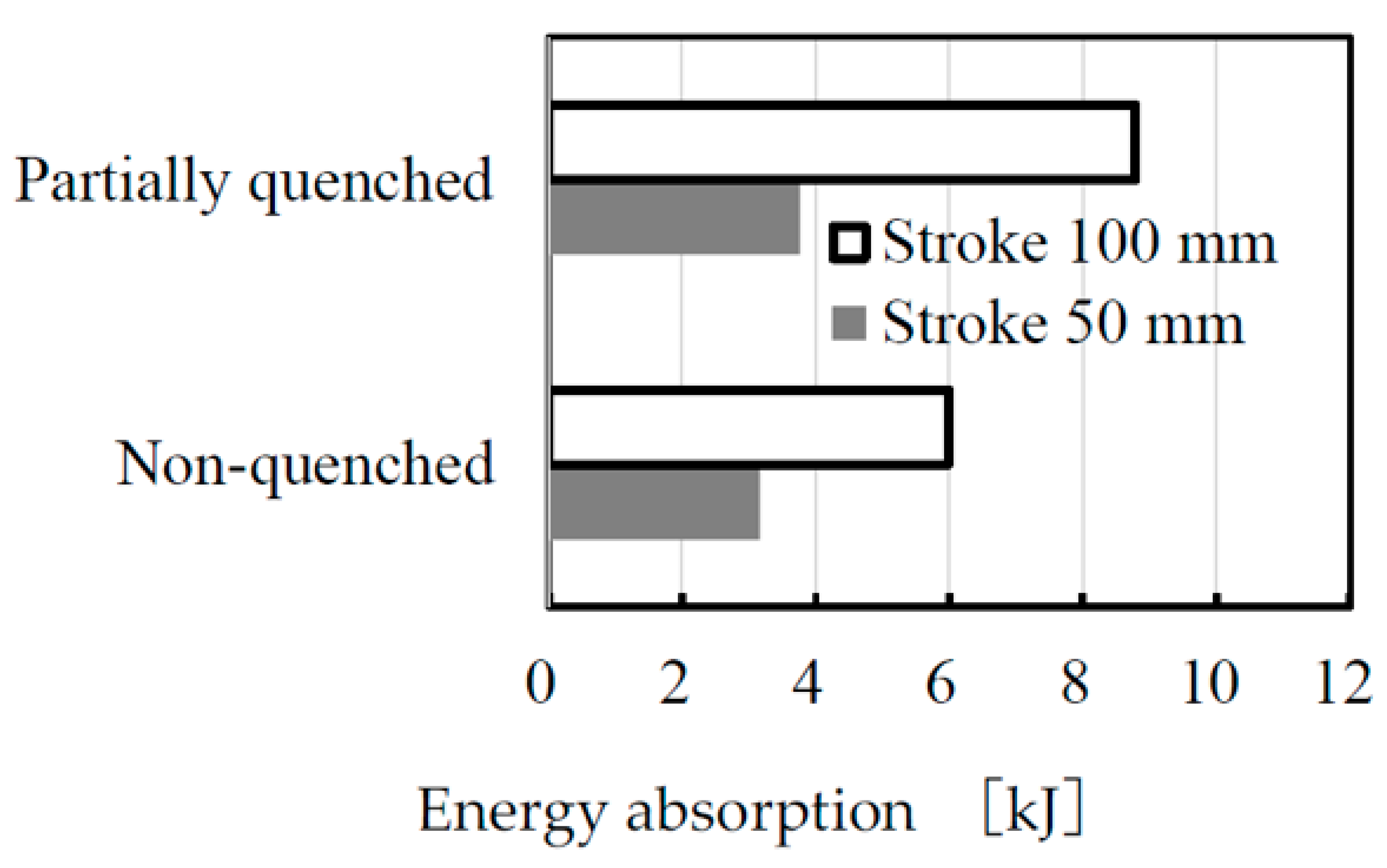
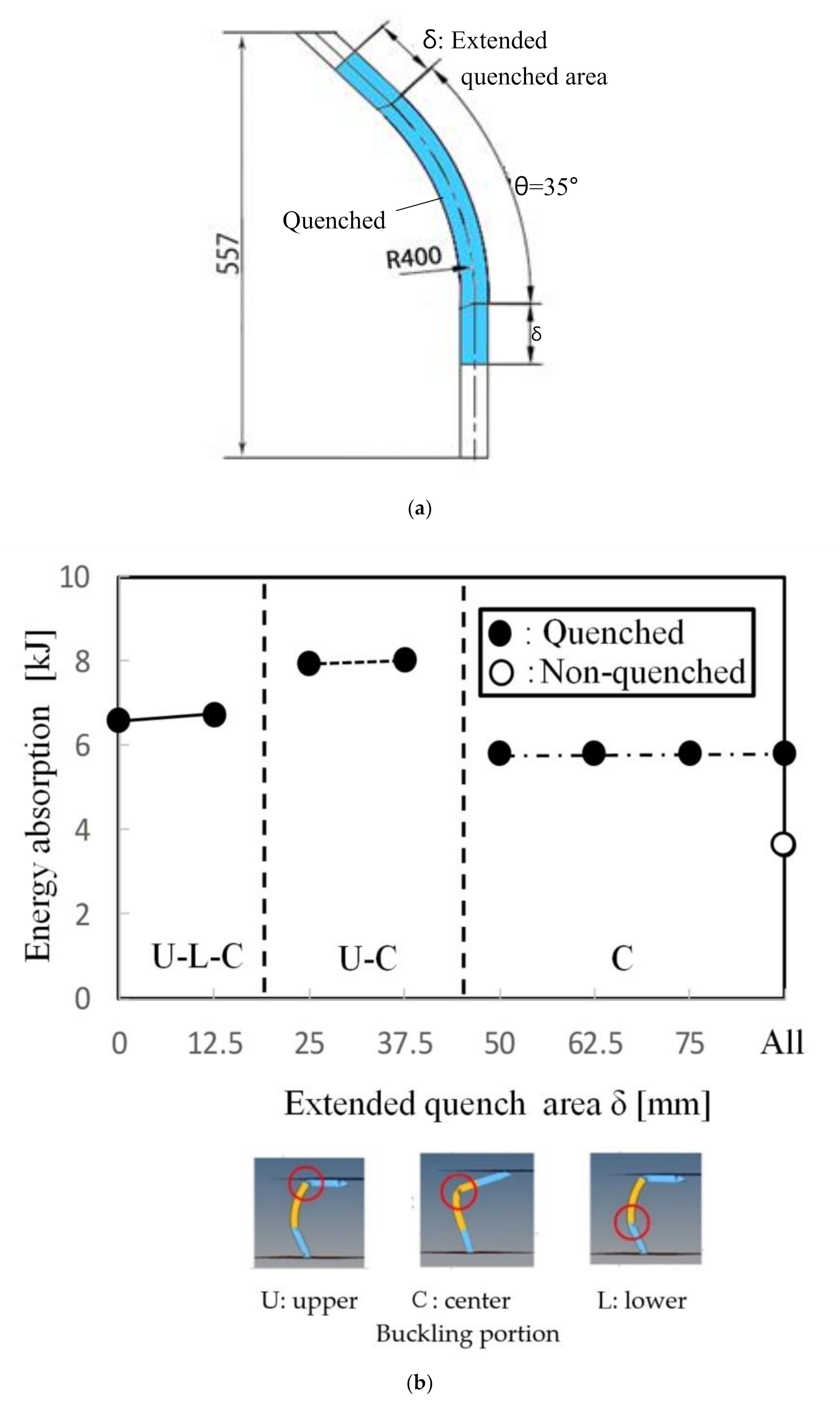
3.3. Influence of the Quenched Area on Crash Deformation

To investigate effect of the quenched area on crash behavior, calculations were carried out using previous finite element (FE) analysis. Table 6 and Figure 16a show the analytical conditions. The calculations were carried out under the bending radius R = 400 mm with extended quenched area δ ranging from 0 to 75 mm. Calculation results are shown in Figure 16b. Figure 16 shows the stroke and buckling location. Buckling occurs at the center portion (C), upper portion (U), and lower (L) portion of curved product. The arrows indicate the order of buckling when the buckling occurred multiple times. As seen in Figure 16, buckling behavior depends on the quenched area. In the case of the products with 50 and 75 mm extended quenched area, the buckling occurrence is same as the crash test of overall-quenched products. In the case of smaller quenched area products, such as the products with 25 and 37.5 mm extended quenched area, the local buckling occurs two times in the crash test. The first buckling occurs at the nonquenched upper part of the product and the second buckling occurs at the bending section. This kind of buckling at bending section leads to rupture in some case. In the case of products with 0 and 12.5 mm extended quenched area, local buckling occurs three times in the crash test. The first buckling occurs at the nonquenched upper part of the product. Then, the second buckling occurs at the nonquenched lower part of the product. Finally, the last buckling occurs at the bending section.

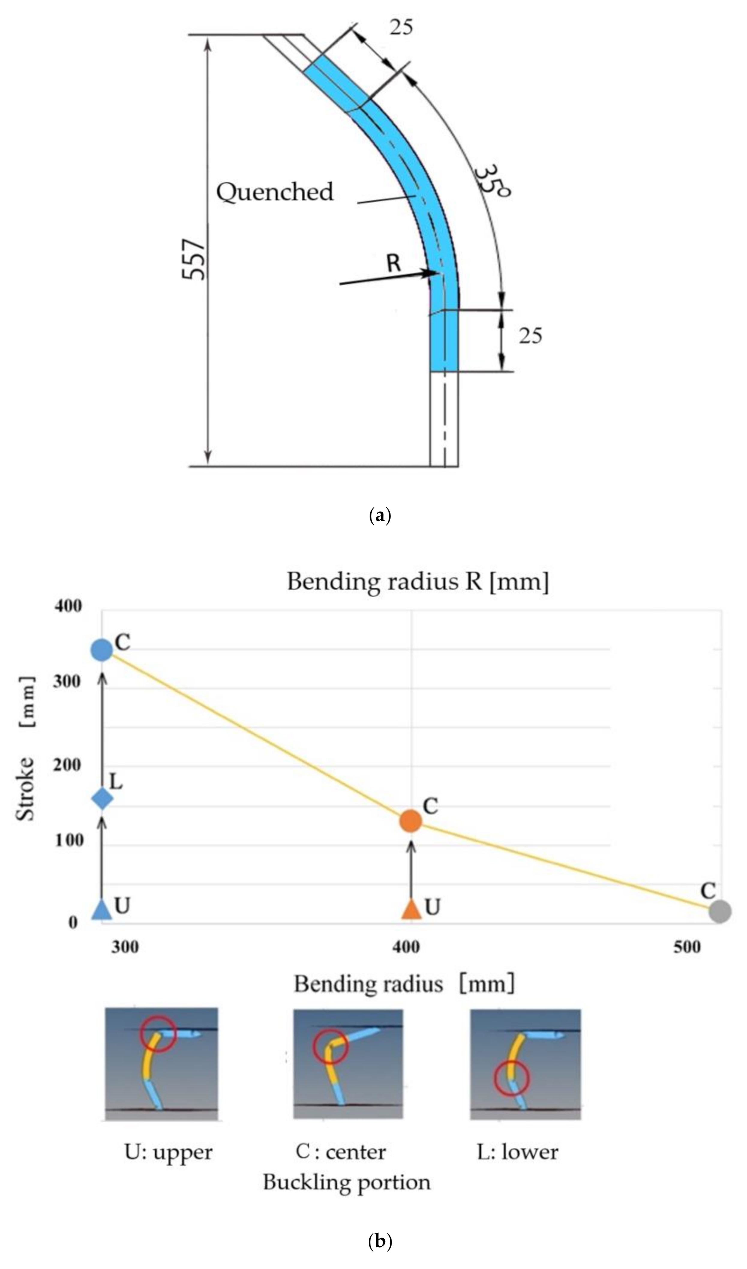
3.4. Influence of Bending Radius on Crash Deformation

To investigate effect of bending radius on crash behavior, calculations were carried out under the same condition (extended quenched area δ = 25 mm) with bending radius R ranging from 300 to 500 mm. Figure 17a shows initial product shape in calculation. The calculation results are shown in Figure 17b. As can be seen from the figure, for the partially quenched products with bending radii greater than 400 mm, buckling easily occurs at the initial stage owing to its larger moment at the bent portion. Thus, it exhibits smaller energy absorption. Contrary, for those partially quenched products with bending radius below 400 mm, local buckling occurs three times.

4. Discussion

From the FEM analysis in the previous section, it is made clear that the buckling behavior significantly changed by changing the partially quenched area. The deformation behavior in the crash test is classified into the following three types: (1) buckling occurs only at the bent portion (C); (2) buckling occurs at the upper nonquenched portion, and then buckling occurs at the center bent portion (U-C); (3) buckling occurs at the upper nonquenched portion, then buckling occurs at the lower nonquenched portion, and finally, third buckling occurs at the center bent portion (U-L-C). Figure 18 shows relationship between the extended quenched area and energy absorption, correspond to the buckling deformations.
The energy absorption of the conventional curved product is 3.5 kJ, whereas the overall-quenched product exhibits a larger value, whose buckling occurs at the bent portion during the initial stage. As shown in Figure 17, in the case of the products with 50 and 75 mm extended quenched area, the buckling occurrence are the same as that in the crash test of the overall-quenched products. For products with a smaller quenched area, such as those with 25 and 37.5 mm extended of the quenched area, the buckling occurs twice. The first buckling occurs at the nonquenched upper portion, and the second buckling occurs at the quenched bent portion. Although this type of buckling exhibits such a large value of energy absorption, as shown in Figure 17, rupture easily occurs, hence its buckling load is varied.
As shown in Figure 18, the most suitable crash characteristic is obtained when local buckling occurs three times during the crash process in the following condition: 0 and 12.5 mm extended quenched area. The first buckling occurs at the nonquenched upper part of the product and the second buckling at the nonquenched lower part of the product and then, the third buckling at the bent portion.
In Figure 19, the effect of partially quenched products on energy absorption is shown. The conventional nonquenched curved product has the smallest energy absorption in the crash test. Due to the effect of its quenching characteristics, the energy absorption of overall-quenched product became 59.3% larger than that of the conventional nonquenched curved product. Furthermore, in this study, the crash characteristics of partially quenched products by 3DQ are investigated. The energy absorption increased 84.6% compared with the energy absorption of conventional nonquenched curved product.

5. Conclusions

In this study, the characteristics of 3DQ curved products were investigated as the fundamental research of the most suitable automotive design for improving the energy absorption capability. Main results are concluded as follows:
  • For partially quenched straight products in the axial crash test, buckling behavior occurred at nonquenched portion can be controlled.
  • For the conventional nonquenched curved product and overall-quenched curved products, buckling occurs at the bent portion at the initial stage in axial crash tests, and its energy absorption was low.
  • The crash deformation of curved partially quenched 3DQ products were performed by FE analysis.
  • For overall-quenched products, buckling occurred at the bent portion and, its energy absorption increased 59.3% compared to the conventional nonquenched curved product.
  • By optimizing the partially quenched area, buckling can be controlled. In this study, the largest energy absorption was obtained from the partially quenched curved product, which is 84.6% larger than the energy absorption of the conventional nonquenched curved product during the crash test.

Author Contributions

Conceptualization, A.T.; Methodology, A.T.; Resources, A.T., K.U. and N.S.; Material provision, K.U. and N.S.; Experimental work, A.T., K.U. and N.S.; Numerical analysis, A.T. and S.S.H.; Data curation, A.T.; Writing—original draft preparation, A.T.; Supervision, A.T.; Project administration, A.T.; Funding acquisition, A.T. All authors have read and agreed to the published version of the manuscript.

Funding

This work was supported by JSPS KAKENHI Grant Number JP20K05172.

Conflicts of Interest

The authors declare no conflict of interest.

References

  1. Watabnabe, K.; Kuriyama, Y.; Inazumi, T.; Fukui, K. World Auto Steel Program Future Steel Vehicle (Third Report). Trans. JSAE 2013, 44, 523–528. [Google Scholar]
  2. Takahashi, M. Current Status and Future Prospects of High-Strength Steel Sheet for Automobiles. J. JSTP 2017, 58, 105–109. [Google Scholar] [CrossRef]
  3. Kojima, N.; Nishibata, T.; Uematsu, K.; Uchihara, M.; Imai KAkioka, K.; Kikuchi, K. The Effect of Process Factors on Performance of Hot Stamped Parts. Trans. JSAE 2007, 38, 321–326. [Google Scholar]
  4. Asai, T.; Iwaya, J. Hot Stamping Drawability of Steel. Proc. IDDRG 2004, 344–354. [Google Scholar]
  5. Dohmann, F.; Hartl, C. Tube hydroforming—Research and practical application. J. Mater. Process. Technol. 1997, 71, 174–186. [Google Scholar] [CrossRef]
  6. Hasegawa, Y.; Fujita, H.; Endo, T.; Fujimoto, M.; Tanabe, J.; Yoshida, M. Development of Front Pillar for Visibility Enhancement. Honda R D Tech. Rev. 2008, 20, 106–113. [Google Scholar]
  7. LSEV World’s First Mass Produced 3D Printed Car. Available online: https://polymaker.com/lsev-worlds-first-mass-produced-3d-printed-car/ (accessed on 9 March 2020).
  8. Tomizawa, A.; Shimada, N.; Kubota, H.; Okada, N.; Sakamoto Yoshida, M.; Yamamoto, K.; Mori, H.; Hara, M.; Kuwayama, S. Development of three-dimensional hot bending and direct quench technology. Nippon Steel Sumitomo Met. Tech. Rep. 2013, 397, 83–89. [Google Scholar]
  9. Tomizawa, A.; Shimada, N.; Hara, M.; Kuwayama, S.; Okahisa, M.; Suyama, T. Development of Three-Dimensional Hot Bending and Direct Quench (3DQ) Mass Processing Technology. In Proceedings of the 5th International Conference on Tube Hydro Forming, Hokkaido, Japan, 24–27 July 2011; pp. 137–140. [Google Scholar]
  10. Tomizawa, A.; Shimada, N.N.; Kubota, H.; Okada, N.; Hara, M.; Kuwayama, S. Forming characteristics in three-dimensional hot bending and direct quench process- Development of three-dimensional hot bending and direct quench technology. J. JSTP 2015, 56, 961–966. [Google Scholar] [CrossRef] [Green Version]
  11. Kubota, H.; Tomizawa, A.; Yamamoto, K.; Okada, N.; Hama, T.; Takuda, H. Effect of cross-sectional shape and temperature distribution on formable range in three- dimensional hot bending and direct quench processes- Development of three-dimensional hot bending and direct quench technology. J. JSTP 2016, 57, 879–885. [Google Scholar] [CrossRef] [Green Version]
  12. Uematsu, K.; Tomizawa, A.; Shimada, N.; Mori, H. Development of Three-Dimensional Hot Bending and Direct Quench Using Robot, Journal of Advance Control. Autom. Robot. 2015, 1, 18–24. [Google Scholar]
  13. Sumitomo Metals Develops High-Precision Drop Weight Impact Test Machine. Available online: https://www.nipponsteel.com/en/news/old_smi/2010/news2010-10-20-01.html (accessed on 25 September 2020).
Figure 1. Three-dimensional hot bending and direct quench (3DQ) machine: (a) appearance photograph and (b) schematic illustration.
Metals 10 01322 g001
Figure 2. 3DQ production system.
Metals 10 01322 g002
Figure 3. Examples of tube cross-section for 3DQ.
Metals 10 01322 g003
Figure 4. Examples of automotive products by 3DQ.
Metals 10 01322 g004
Figure 5. Example of tube temperature of in 3DQ process (feed speed 80 mm/s).
Metals 10 01322 g005
Figure 6. Circumferential hardness distribution of 3DQ product (40 mm × 40 mm and thickness 1.8 mm).
Metals 10 01322 g006
Figure 7. Microstructure of product by 3DQ (40 mm × 40 mm and thickness 1.8 mm): (a) 0.2 mm from outer surface, (b) thickness center, and (c) 0.2 mm from inner surface.
Metals 10 01322 g007
Figure 8. Longitudinal hardness distribution of the partially quenched straight product.
Metals 10 01322 g008
Figure 9. Deformation of the partially quenched straight tube in the axial crash test.
Metals 10 01322 g009
Figure 10. Energy absorption of the partially quenched straight tube in the axial crash test.
Metals 10 01322 g010
Figure 11. Initial product shape in axial crash test: (a) overall-quenched, (b) partially quenched, and (c) finite element method (FEM) model.
Metals 10 01322 g011
Figure 12. Comparison of crash deformation of overall-quenched product between experiment and simulation in axial crash test: (a) initial product shape, (b) axial stroke = 15 mm, (c) axial stroke = 150 mm.
Metals 10 01322 g012
Figure 13. Comparison of crash deformation of partially quenched product between experiment and simulation in axial crash test: (a) initial product shape, (b) axial stroke = 15 mm, (c) axial stroke = 85 mm, and (d) axial stroke = 177 mm.
Metals 10 01322 g013
Figure 14. Relationship between load and stroke of overall-quenched product in axial crash test.
Metals 10 01322 g014
Figure 15. Relationship between load and stroke of partially quenched product in axial crash test.
Metals 10 01322 g015
Figure 16. Relationship between extended quenched area and the stroke at buckling occurred: (a) initial product shape and (b) calculation results.
Metals 10 01322 g016
Figure 17. Relationship between bending radius and the stroke at buckling occurred for partially quenched product with extended quenched area δ = 25 mm: (a) initial product shape and (b) calculation results.
Metals 10 01322 g017
Figure 18. Relationship between the extended quenched area and energy absorption in crash test: (a) initial product shape and (b) calculation results.
Metals 10 01322 g018
Figure 19. Energy absorption of product with optimized partially quenched area (see Figure 18).
Metals 10 01322 g019
Table 1. Main specifications of experimental three-dimensional hot bending and direct quench (3DQ) machine.
Maximum Induction Heating Output300 kW
Frequency of induction heater9.8 kHz
Maximum feed stroke1700 mm
Maximum feed speed120 mm/s (at load 5 kN)
Payload of robot165 kg
Table 2. Chemical compositions of material (mass %).
CSiMnB
0.210.221.200.0015
Table 3. Conditions of axial crash test.
Cross-section of Specimen50 mm × 70 mm
Specimen thickness1.8 mm
Partially quenched specimen
(see Figure 9)
Partially quench area: 30 mm × 4
Nonquenched area: 10 mm ×5
Impactor weight430 kg
Impactor speed7–10 m/s
Table 4. Analytical conditions (see Equation (1))
SymbolItemNonquenched AreaQuenched Area
ρInitial density (kg/mm3)7.85 × 10−6
EYoung’s modulus (GPa)210
νPoisson’s ratio (−)0.3
aYield stress (GPa)0.61.6
bStrength coefficient (GPa)1.7543.978
nStrain hardening exponent (−)0.36630.3377
Table 5. Boundary conditions.
Location of SurfaceRestriction of TranslationRestriction of Rotation
X axisY axisZ axisX axisY axisZ axis
TopFixedFixedFreeFixedFixedFixed
BottomFixedFixedFixedFixedFixedFixed
Table 6. Analytical conditions.
Bending Angle θ35 (Deg)
Bending radius R300, 400, 500 (mm)
Extended quenched area δ0, 12.5, 25, 37.5, 50, 75 (mm)

