Article

Design of Wear-Resistant Diecast AlSi9Cu3(Fe) Alloys for High-Temperature Components

1
Department of Management and Engineering, University of Padova, Stradella San Nicola 3, I-36100 Vicenza, Italy
2
Veneto Nanotech Spa, Via delle Industrie, 5 I-30175 Venezia Marghera, Italy
*
Author to whom correspondence should be addressed.
Metals 2020, 10(1), 55; https://doi.org/10.3390/met10010055
Submission received: 24 November 2019 / Revised: 22 December 2019 / Accepted: 24 December 2019 / Published: 28 December 2019
(This article belongs to the Special Issue Dedicating to Professor John Campbell's 80th Birthday)

Abstract

:
Type AlSi9Cu3(Fe) alloy has been modified by alloying with iron, manganese, and chromium elements to develop wear-resistant diecast hypoeutectic Al–Si–Cu alloys that can be applied for high-temperature applications. Several alloys have been produced by varying iron, manganese, and chromium levels (0.80, 1.00, 1.20 wt.% for Fe; 0.25, 0.40, 0.55 wt.% for Mn, and 0.06, 0.10 wt.% for Cr). Brinell hardness measurements and pin-on-disk wear tests have been conducted from room temperature up to 200 °C. The microstructural changes that occurred with the different alloying levels have been quantitatively examined by metallographic and image analysis techniques. The results showed how the increasing content of the Fe, Mn, and Cr promoted the precipitation of both primary and secondary Fe-enriched particles, mainly with polyhedral, blocky, and star-like morphologies. These compounds showed high hardness that is not affected by chemical composition and morphology variation. At high temperatures, the diecast alloys always showed lower average hardness and wear resistance, especially at 200 °C; however, a greater amount of Fe-rich particles can compensate the alloy softening.

1. Introduction

The growing demand of Al-based alloys in the automotive sector is mainly ascribed to the need of vehicles’ weight reduction as well as to increase their performance. Concurrently, the use of lightweight materials aims to meet the energetic and environmental requirements. Due to their excellent castability and high mechanical properties referred to the weight, Al–Si alloys are widely used among the Al foundry alloys in the automotive industry.
Besides the tensile and fatigue properties, many efforts have been made to improve the tribological properties of Al–Si-based alloys, especially for high-temperature components such as pistons, cylinder block, and cylinder liners in internal combustion engines [1,2,3,4].
Aluminum alloys do not exhibit sufficient wear resistance [5]; however, the tribological behavior of Al alloys can be improved by properly tailoring the type and amount of alloying elements as well by the introduction of ex-situ reinforcing phases [6,7] and by postcasting heat treatments [8].
Silicon alloying is the most popular route to improve the wear response of casting Al alloys; by increasing the Si fraction, the formation of hard Si crystals is stimulated and consequently, the hardness and the wear resistance increase but, conversely, the machinability decreases. Thus, although hypereutectic Al–Si alloys (Si > 13 wt.%) are usually used for tribological applications, the Si content does not exceed 20 wt.% in commercial applications [9].
Recently, Taghiabadi et al. [10] have reported how an optimized addition of iron can improve the tribological behavior of Al–Si alloys. Furthermore, a few percent of iron enhances the mechanical properties and the thermal stability of the material at high temperatures [11].
Iron is commonly considered an impurity element of Al–Si casting alloys, which detrimentally affects the final mechanical properties. This is typically ascribed to the formation of brittle β-Al5FeSi (β-Fe) phase, which appears as needles-like particles in the microstructure; as the needle tips act as stress concentration points, the presence of β-Fe phase leads to a general reduction of tensile properties (ductility and ultimate tensile strength) and wear resistance [12]. However, a high Fe level is demanded in aluminum diecasting alloys to alleviate or eliminate die soldering phenomena occurring in high-pressure diecasting (HPDC) processes.
Thus, a typical solution adopted in Al–Si alloys to contrast the negative effects of β-Fe needle-like particles consists in the addition of transition metals (Mn, Cr, Ni, Mo, Co) and some alkaline earth metals (Sr and Be) which modify the morphology of β-Fe phase into a less harmful and more compact shape [13,14,15].
It is largely known [15,16,17] that both manganese, the most diffuse alloying element, and chromium induce the precipitation of hard primary α-Al15(Fe,Mn,Cr)3Si2 (α-Fe) particles (i.e., sludge [18]) instead of needle-like β-Fe phase. As reported in [19], the replacement of β-Fe with α-Fe phase leads to enhancement of wear resistance. The α-Fe particles show a better bonding with the α-Al matrix compared with the β-Fe phase and, therefore, they reduce the possibility of crack formation at the interface matrix/particle.
The sludge formation is a typical problem in HPDC foundry, where the molten bath temperatures are generally lower with respect to other foundry processes in order to extend the operating life of die and tools.
Beside the melting and holding temperature and time, the alloy’s chemistry influences the sludge formation. It is widely accepted how the sludge factor (also called iron equivalent value [20,21]) can be considered a useful parameter to predict the precipitation of primary α-Fe particles. The sludge factor can be determined from the initial contents of iron, manganese, and chromium in the alloy as [22,23]:
Sludge Factor (SF) = (wt.%Fe × 1) + (wt.%Mn × 2) + (wt.%Cr × 3)
In this scenario, the automotive industry requires the best compromise to achieve excellent performances in terms of wear and high-temperature resistance by using materials and processes suitable for mass production. Because of that, wear-resistant automotive components are produced by hypereutectic Al–Si alloys by means of low-pressure die casting instead of HPDC due to the high density of silicon crystals in hypereutectic alloys, which reduce the life of dies and tools.
On the other side, the capability to enable the use of HPDC can exhibit several advantages such as high production rate, low cycle time, and production of castings with greater geometrical complexity. This can be achieved by preserving the use of hypoeutectic Al–Si alloys necessary to ensure low wear rate of dies and by a proper design of sludge particles to optimize the wear and high-temperature properties.
In this study, a diecast AlSi9Cu3(Fe) alloy was analyzed. Variations of the chemical composition were systematically obtained by gradually increasing the content of iron, manganese, and chromium in accordance to the tolerance limits of the EN 1706:2010 standard [24]. This paper investigates a set of proposed alloys with increasing amounts of Fe, Mn, and Cr alloying elements, taking into account their microstructure, hardness, and wear resistance at high temperature.

2. Materials and Methods

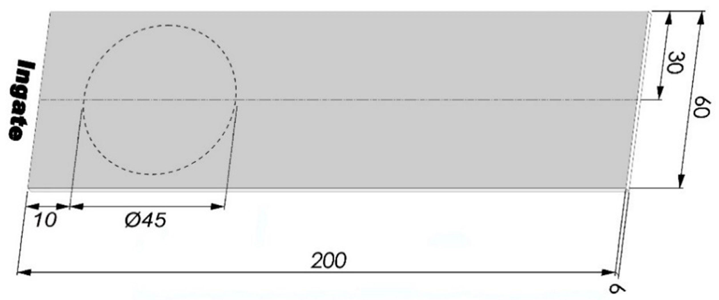
2.1. Experimental Alloys and Casting Parameters

In this work, a secondary AlSi9Cu3(Fe) foundry alloy was chosen as base alloy (Alloy 1) and melted in a gas-fired chamber furnace at 760 ± 5 °C. The chemical composition of the base material is summarized in Table 1. The different experimental alloys were then prepared by progressively adding precise amounts of Al–25Fe, Al–25Mn and Al–10Cr master alloys, which gradually dissolved into the liquid bath. The homogeneity and dissolution of the elements was ensured by holding the liquid metal in the furnace for 1 h. The temperature was then gradually decreased to 690 ± 5 °C, and the liquid metal was degassed by using an argon–sulphur hexafluoride mixture (Ar/SF6 0.2%) for 10 min.
Eighteen different alloys were produced by varying the content of Fe and Mn over three targeted levels (0.8, 1.0, 1.2 wt.% for Fe; 0.25, 0.40, 0.55 wt.% for Mn) and Cr over two levels (0.06, 0.10 wt.%). The measured contents of iron, manganese, and chromium in the final alloys are shown in Table 2; they result to be within the composition tolerance limits of the AlSi9Cu3(Fe) alloy, while the amount of the other elements remains nearly similar to the base alloy; the sludge factor, SF, ranged from 1.32 to 2.90.
A multicavity die was used to produce cast-to-shape specimens by means of a cold chamber diecasting machine. The die allowed to cast two flat and cylindrical tensile specimens, one Charpy specimen with V-notch and one plate from each shot. Further details of the HPDC machine and casting process parameters are reported in [25]. More than 40 castings were produced for each alloy composition; the specimens were stored at room temperature for six months and then analyzed.

2.2. Wear Testing

For the tribological tests, 45 mm diameter rotating discs were drawn from the diecast plates. Preliminary X-ray inspections revealed the presence of casting defects in the region far from the ingate, as reported in [26]; therefore, the discs were drawn close to the ingate of the plates, as shown in Figure 1. Dry sliding wear experiments were carried out at different temperatures by means of a pin-on-disc testing machine. The material used as 10 mm diameter round pin was a tempered EN2C45 steel (surface hardness of 58 HRc). The pin surface was ground with 600 grit abrasive paper to guarantee identical surface roughness before each test. Prior to the tribological tests, the 45 mm diameter discs were machined for removing 2.0 ± 0.1 mm from the surface, in order to provide a flat and fresh metal surface. All the wear discs were then polished up to 0.5 μm average roughness (Ra), which was evaluated by using a Taylor Hobson Surtronic 3+ stylus profilometer (AMETEK Inc, Berwyn, PA, USA) with a resolution of 0.01 μm. The discs were cleaned using acetone before wear testing in order to remove any external contamination from the surface. Dry sliding tests were carried out in air at room temperature, 150 ± 5 °C, and 200 ± 5 °C, with a constant sliding speed of 0.1 m/s and a load of 15 N for a distance of 540 m; the test time was about 90 min long.
For high-temperature experiments, each disc was heated and maintained for 30 min at temperature before wear testing. Thus, for the tests at elevated temperatures, the discs were overall exposed for approximately 120 min. Each test was repeated four times on new specimens. The mass loss was measured by using an electronic balance with a resolution of 0.1 mg and used for the analysis of the wear rate; the density of fully dense material was here assumed to be 2.770 g/cm3, as indicated in [11].

2.3. Hardness and Nanoindentation Measurements

Hardness tests were performed at different temperatures on machined specimens by using a Brinell hardness testing procedure according to the standard ASTM E10-15a [27]. The hardness tests were carried out at room temperature, 150, and 200 °C using a spherical indenter (tempered steel) with a diameter of 2.5 mm and a load of 60 kgf. For hardness measurements at high temperature, each specimen was heated and maintained for about 120 min at the testing temperature in order to compare the hardness results with the wear data at high temperature. The hardness of each alloy, under the different thermal conditions, was obtained as an average value of five measurements.
Nanoindentation tests were performed in order to determine the hardness and reduced modulus of primary Fe-rich particles. All the experiments were conducted at room temperature using the nanotest indentation module with a three-side Berkovich diamond indenter. A loading rate of 0.33 mN/s with a maximum load of 20 mN and a constant dwell time of 30 s were applied. Optical microscopy integrated in the indenter device was used for finely positioning the indenter tip on the particles. Single indents were carried out on Fe-bearing particles larger than 15 μm to avoid any matrix influence on the measurements. Three alloys with different Fe, Mn, and Cr levels were selected for the nanoindentation tests, and, at least, 30 particles were analyzed for each alloy. Finally, hardness and Young’s modulus were evaluated by applying Oliver and Pharr’s model on the load/penetration depth curves [28].

2.4. Microstructural Investigations

Samples of 6 × 15 × 10 mm3 were drawn from the cross section of the diecast plates and prepared according to standard metallographic procedure. Microstructural investigations were carried out using an optical microscope (OM, Leica Microsystems GmbH, Wetzlar, Germany) and a scanning electron microscope (SEM, FEI Quanta™ 250, Thermo Fisher Scientific, Hillsboro, OR, USA) equipped with an energy-dispersive X-ray spectrometer (EDS, EDAX™, AMETEK BV, Tilburg, The Netherlands); the OM micrographs were then processed by using an image analysis software for a quantitative characterization. The polished specimens were etched using a sulphuric acid solution at 70 °C to more easily detect the α-Fe phase by image analyzer. According to the results in Reference [29], only Fe-rich particles over 10 µm in diameter were selected as primary phase and, thus, considered for a characterization of sludge. The worn out surfaces and the wear mechanisms were not studied in the present work.

3. Results and Discussion

3.1. Microstructural Analysis

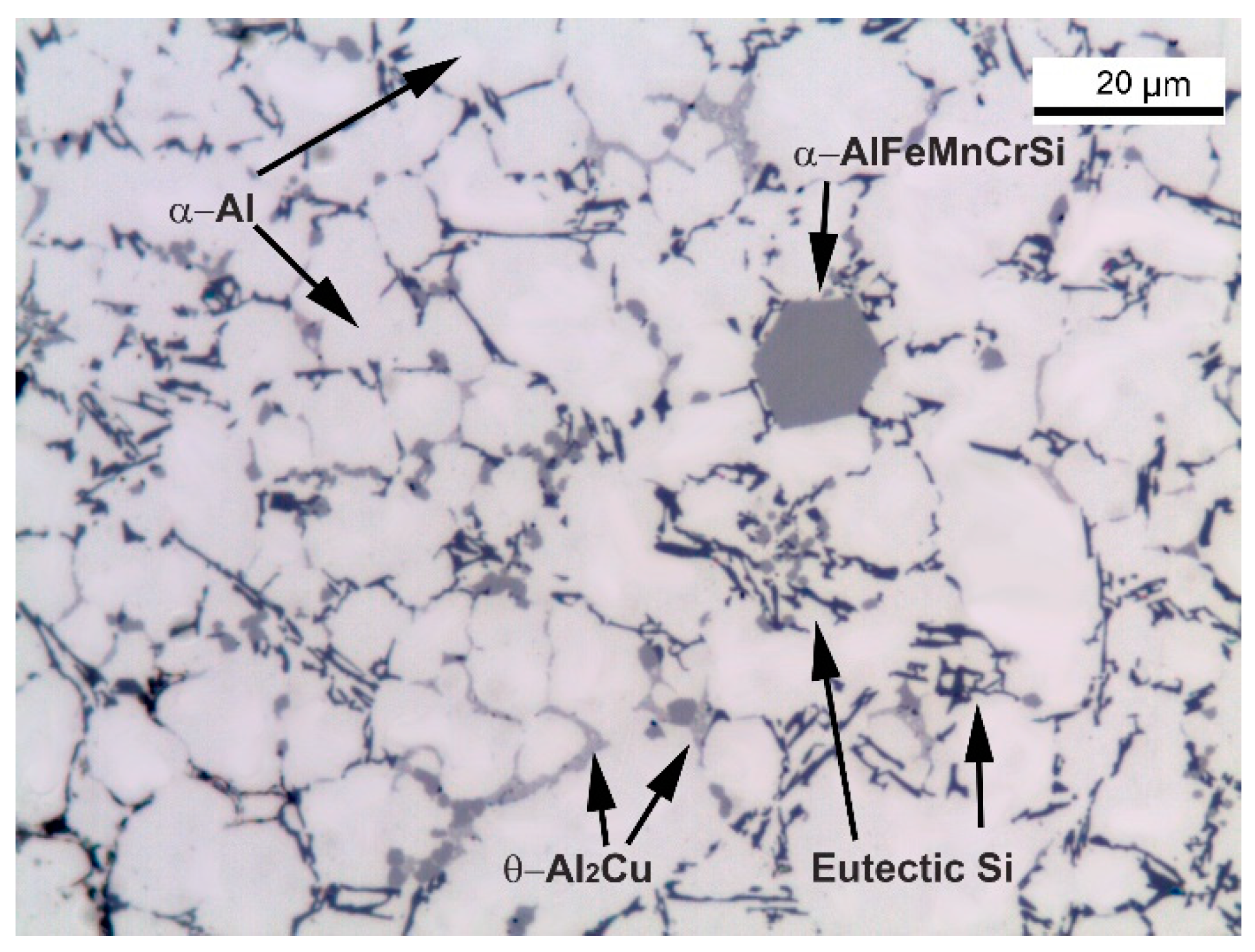
3.1.1. Diecast AlSi9Cu3(Fe) Alloy

The microstructure of base alloy (Alloy 1) in Figure 2 mainly reveals an α-Al solid solution and an eutectic mixture of Al and Si. The α-Al phase consists of fine equiaxed and less-branched dendrites. Such a morphology is due to the intense shear and to the high cooling rate generally achieved in the HPDC process, which favor greater nucleation than growth of the α-Al phase [30].
The eutectic Si particles appear fine and fibrous on the casting surface owing to higher cooling rates, while they assume a coarse plate-like morphology at the center of the specimen, as typically observed in the unmodified Al–Si alloys.
The α-Al15(Fe,Mn,Cr)3Si2 and Al2Cu phases were also identified as frequent intermetallic compounds (Figure 2). Besides Al2Cu phase, another Cu-containing phase was occasionally observed in the AlSi9Cu3(Fe) alloys and identified as Q-Al5Mg8Cu2Si6 phase [31].
The intermetallic compounds generally appear in the interdendritic region and in the grain boundaries; moreover, α-Fe phase appears as polyhedral particles, while the Al2Cu phase precipitates in the forms of blocky-like and lamellar particles, the latter as product of binary L → α-Al + Al2Cu eutectic reaction.
Ferraro et al. [29] found for similar alloys that the distribution of the α-Fe particles’ size shows a bimodal distribution; in such work, the “α1-Fe” and “α2-Fe” labels are used to indicate the particles larger than 10 μm and those ranging from few microns up to ~10 μm, respectively (Figure 3). While the smaller α2-Fe particles are generally referred to as secondary intermetallic compounds, the coarser α1-Fe ones, comparable in size to the α-Al cells, are considered as primary and, thus, defined as sludge particles [22,23].
The α1-Fe particles are generally formed in the ladle (or feed pipe) when the melt is transferred to the cold chamber diecasting machine or in the shot sleeve before the plunger moves forward, where the cooling rate can achieve 102 °C/s during solidification [32]. On the other side, the α2-Fe particles are believed to be nucleated inside the die cavity under a cooling rate higher than 103 °C/s during solidification [33].
It has been recently reported how the stoichiometry of the α-Fe compounds is α-Al12(Fe,Mn,Cr)3Si2 [34]; these compounds were described by Mondolfo [35] as a solid solution of iron and chromium in the Al15Mn3Si2 phase, where iron and chromium atoms can substitute manganese atoms, resulting in the final α-Al15(Fe,Mn,Cr)3Si2 stoichiometry. Fabrizi et al. [36] highlighted how the variability of the Fe, Mn, and Cr concentration in the α-Fe precipitates is related to the initial alloy composition.

3.1.2. Influence of High Temperature on the Microstructure

Preliminary investigations of the nanoscale precipitates formed by thermal exposure during high-temperature tests were carried out by bright-field transmission electron microscopy (TEM).
Before thermal exposure, fine precipitates with an average size of few nanometers are found throughout the α-Al matrix (Figure 4a); when the alloy is thermal treated at 150 °C for 30 min, the density of fine and slightly coarser precipitates seems to increase (Figure 4b). At 200 °C, the fine precipitates completely disappear, and coarse platelets with {100}Al habit plane appear in the α-Al phase (Figure 4c).
The key factor to explain the microstructural evolution at higher temperature is the non-equilibrium state of the diecast AlSi9Cu3(Fe) plates related to the rapid cooling during solidification in the HPDC process. The EDS measurements in the as-diecast alloys revealed that 1.5 ± 0.3 wt.% Cu, 0.5 ± 0.1 wt.% Mg and 2.4 ± 0.7 wt.% Si are retained in supersaturated solid solution (SSSS) inside the α-Al dendrites. According to the CALPHAD equilibrium calculations, the solid solubility of these elements is negligible at room temperature, while the solubility of Si, Cu, and Mg at 200 °C amounts about to 0.007, 0.110, and 0.003 wt.%, respectively. The inhomogeneous solid solution supersaturation due to the diecasting process enhances the chemical driving force for diffusion of Si, Cu, and Mg solute atoms, leading to a controlled decomposition of the SSSS and the precipitation of strengthening fine particles.

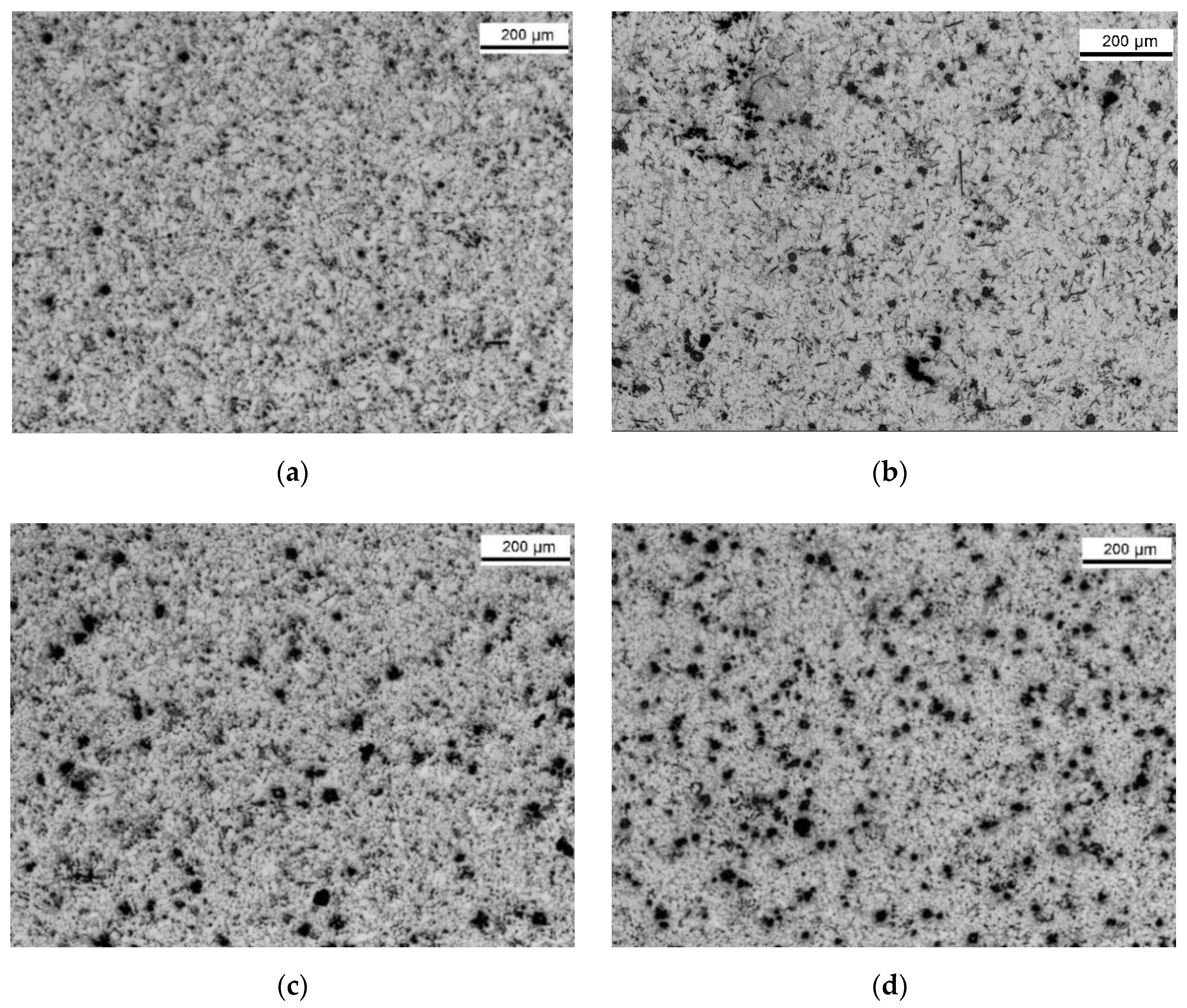
3.1.3. Influence of Iron, Manganese, and Chromium on the Microstructure

The microstructures of the center of the plates produced with different Fe, Mn, and Cr contents are reported in Figure 5. The α1-Fe sludge particles, appearing as dark compounds after chemical etching, generally assume star-like and polyhedral morphologies. Their amount and dimensions increase by increasing the Fe, Mn, and Cr levels in the alloy, in accordance with the SF value obtained through Equation (1). The graph in Figure 6 shows the sludge fraction of the experimental alloys as a function of their sludge factor; the sludge amount increases proportionally with the SF. At the same time, more α2-Fe particles form and, therefore, the volume fraction of these increases. However, it has been recently demonstrated how the sludge formation prevails over the whole precipitation of α-Fe phase [37].
Needle-like β-Al5FeSi particles are also observed in the alloys with higher Fe:Mn ratio; the most critical alloys appeared to be the Alloy 13 (Figure 5b) and the Alloy 14, having a Fe:Mn ratio of 5.81 and 6.27, respectively. Here, the manganese and chromium levels are not high enough to change the crystallization mechanism of the Fe-rich particles from acicular to blocky shape; therefore, beside blocky α-Fe phase, β-Fe needles coexist in the microstructure.
Upon increasing the Mn and Cr levels such as in Alloys 15 and 18, the amount and the dimension of sludge compounds notably increase if compared with the diecast AlSi9Cu3(Fe) base alloy (see Figure 5c,d). Needle-like β-Fe particles are also observed, but they appear smaller compared with those in Alloy 13; moreover, the morphology of sludge seems to change towards a more irregular and star-like shapes.
The local variation of α1-Fe fraction along the cross section of diecast plates was studied, and the results are summarized in Figure 7. Each point of the curves represents the average sludge fraction obtained from at least three micrographs of about 620 × 460 µm2; the fraction profile was then realized by acquiring micrographs at 600 µm intervals from casting surface to the center.
The α1-Fe compounds tend to segregate in the central zone of the plate, which was the region subsequently investigated by wearing tests. On the other side, the surface layer shows few sludge crystals (see Figure 7). This segregation mechanism has been largely described in literature [16].

3.2. Hardness and Nanoindentation

Nanoindentation tests were performed on sludge particles to verify their individual specific hardness. As found in [36], the different contents of iron, manganese, and chromium in the experimental alloys lead to a variation of the chemical composition of the sludge particles and, potentially, their mechanical properties. Therefore, sludge particles in three alloys with different iron, manganese, and chromium levels (Alloys 1, 13, and 18) were analyzed. In addition, the relationship between sludge morphology and the hardness was also investigated by testing polyhedral and star-like particles in Alloy 18 with the highest sludge fraction (Figure 8).
The average hardness and reduced modulus of the α1-Fe particles and α-Al matrix are given in Table 3.
Sludge particles exhibit high hardness and reduced modulus, which are almost constant regardless of the iron, manganese, and chromium levels in the alloy; therefore, the sludge particles can be effectively considered a “hardening phase”; in addition, the different sludge morphology seems to not be reflected in the hardness value (Table 4).
Although the average hardness values estimated in the present work well correlate with the values of the α-AlFeMnSi phase reported in literature [38,39], Chen and co-workers [39] found slightly higher reduced modulus (~175 GPa). However, this discrepancy is in agreement with the accuracy of the characterization method and it could be related to different causes such as sample preparation, instrument calibration, and contact point detection as well adoption of different calibration procedures for the estimation of the reduced modulus [40].
Brinell hardness measurements were also conducted at different temperatures to investigate the influence of the iron, manganese, and chromium contents on the overall hardness of the experimental alloys. The average hardness values as a function of the sludge factor are plotted in Figure 9. At room temperature, the hardness ranges from 80 (Alloy 1 with a SF of 1.32) to 95 HB (Alloy 18 with SF of 2.90) with an increasing tendency by greater content of iron, manganese, and chromium. This behavior can be mainly ascribed to greater fraction of Fe-rich particles, which, as it results from Figure 6, is strictly related to the increase of SF.
At higher temperatures, the experimental AlSi9Cu3(Fe) alloys show lower average hardness, especially at 200 °C, where the solute diffusion of Cu, Si, and Mg is more effective in promoting precipitate coarsening within the α-Al matrix and it contributes to the alloy softening (see Figure 4c). At 150 °C, the increased amount of fine and slightly coarser precipitates with respect to the as-diecast alloys (see Figure 4b) leads to a reduction of the residual solid solution, which, therefore, less contributes to the overall hardness. The volume fraction of strengthening particles cannot compensate the change in the matrix solute level. However, the hardness shows again an increasing tendency by higher Fe, Mn, and Cr levels. An improved hardness is expected to lead to an increasing wear resistance.

3.3. Wear Behaviour

Figure 10a shows the average wear rate of the experimental AlSi9Cu3(Fe) alloys against the area fraction of sludge compounds for the different testing temperatures. The wear rate decreases progressively with the sludge fraction, and this behavior is even more pronounced by increasing the temperature during wear testing. On the other side, the variations of the wear rate at different temperatures well fit with the sludge factor too (Figure 10b). The results suggest that for the testing conditions considered in this study, the wear rate of the diecast AlSi9Cu3(Fe) alloys may be predicted by the SF of the alloy using a linear regression model. The slope of the fitting curves reported in Figure 10 increases progressively by increasing the temperature from room temperature up to 200 °C. The wear rate (in mm3/m·N × 10−3) can be statistically modelled for the different temperatures using a relationship of the type:
Wear rate = a × SF + b,
where the coefficients, a and b, as well as the R2 and p-values are indicated in Table 5.
Recently, Ferraro et al. [41] showed how, at room temperature, the tensile mechanical properties of diecast AlSi9Cu3(Fe) alloys do not exhibit a significant drop when the fraction of sludge particles is increased through iron, manganese, and chromium addition.
On the other side, the mechanical properties at high temperatures of Al–Si-based alloys can be improved through precipitation of dispersoids, which are thermally stable and more resistant to coarsening than traditional Mg2Si and Al2Cu precipitates. Unconventional Al–Si alloys have been developed by adding Cu and Ni, and transition elements such as Ti, V, Mn, Cr, and Zr [42,43,44,45]. Among the transition alloying elements, Mn combined with Cu and Ni turned out to be the most effective elements to improve the high-temperature strength of the material.
The mild wear mechanism of AlSiCu(Fe) gravity-cast alloys has been studied and described in literature [3,4,5,7,8,10,12]. High tangential stresses on and below the sliding surface cause the formation of cracks in the material plastically deformed during dry sliding. These cracks can propagate and coalesce, leading to fracture of the particles starting from the surface [4]. A fraction of these particles goes out from the wear track, while the remaining part is accumulated on the wear surfaces, particularly at the bottom of the grooves formed in the early stages of sliding. The sliding behavior with a constant action of the pin at the bottom of the track accounts for this concentration of sludge and other hard oxide particles in the groove surface. Moreover, the local temperature combined with normal pressure promoted the formation of a sort of compact and hard metal matrix composite in the surface layer with a significant beneficial effect on tribological behavior of the material.
Therefore, the enhancement in the wear properties by increasing the iron, manganese, and chromium content can be assigned to hardening effects of the hard α-Fe intermetallic compounds, which help the substrate to support the load. The hardness increase of the diecast AlSi9Cu3(Fe) alloy through the addition of iron, manganese, and chromium results in a wear resistance improvement, as predicted by Archard wear law [46].
The α-Fe intermetallics have a compact morphology and they have modest tendency to develop surface and sub-surface microcracks. Furthermore, the α-Fe phase forms a rough interface with the matrix, and its bonding with the matrix declines the possibility of decohesion at the interface (see Figure 11a).
On the other side, the β-Fe needle-like compounds are hard and brittle phase, and much more easily subjected to fracture mechanism under load than the small eutectic Si particles or α-Al matrix. For this reason, the β-Al5FeSi needles are considered as harmful for the final mechanical properties of the alloy. Micro-cracks tend generally to initiate at these particles (see Figure 11b), facilitating the propagation of the macro-cracks. The β-Al5FeSi compounds exist as discrete particles with a highly faceted nature in the alloy matrix that can fracture through cleavage mechanism, particle–matrix decohesion [47], or separation of folded bifilms [48]. Moreover, sharp edges of the β-Fe needle-like compounds represent stress concentration points within the alloy’s matrix.
It was observed how the experimental alloys with higher density of β-Al5FeSi phase (Alloys 13 and 14, having higher Fe:Mn ratio) do not suffer a great decrease in the wear properties. Therefore, the effect of β-Al5FeSi needles on the mechanical properties of the alloy significantly depends on their size and volume fraction. This means that only the presence of large β-platelets in the microstructure might lead to higher embrittlement of the alloy and to larger microcracking tendency, and delamination of the surface can strongly occur. In the present work, the β-needles show maximum length of about 25 μm and their presence coexists with both coarse and fine blocky α1-Fe and α2-Fe compounds, respectively.
The material loss during dry-sliding at high temperature is generally controlled by two antagonistic effects: wear process and oxidation. Higher temperatures, such as 150 and 200 °C, led progressively to greater wear rates with respect to those obtained at room temperature. Furthermore, the wear rate seems to not be linearly proportional to the temperature, but it increased significantly at 200 °C. In general, the strength of Al–Si–Cu alloys drastically decreases for temperatures higher than 200 °C [49], where plastic relaxation mechanisms become increasingly dominant.
The effect of high temperature is to promote the compactness and average resistance of the metal-matrix-composite surface layer described above, and to accelerate the oxidation of the residual metal in the particles. If there are the conditions to allow the formation of the surface layer before breakdown, then the wear becomes very low [6]. On the contrary, if the surface layer is not yet compacted, then particles’ removal, damages to surface, and delamination occur, strongly reducing the whole wear resistance.
Zhang and Alpas [5] found out how the transition mechanism from mild to severe wear is realized by a joint combination of experimental variables such as the sliding velocity, the applied load, and contact surface temperature. Severe wear mechanism is related to a massive plastic deformation as a consequence of thermal softening of the alloy. In literature [5], the wear mechanism maps for Al-based alloys show how the conditions to achieve a severe wear have not been reached in the present work and the delamination wear is the controlling mechanism.
Figure 12 illustrates how the friction coefficient evolves with the sliding distance for different experimental conditions. The Fe, Mn, and Cr alloying addition seems to not largely influence the friction behavior at room or high temperatures. However, it is evident how that friction coefficient varies over a narrow band.
The friction coefficient at room temperature starts off from a low value (~0.2) and increases rapidly. At the initial stage of the test, the surface roughness and preparation as well as the asperity deformation play important roles in friction determination; thus, the contribution of adhesion to the friction is expected to be moderate.
After a peak at about 20 m slid distance, the friction coefficient decreases, most likely due to the surface asperities flatting. During this phase, the presence of wear debris on the surface causes several oscillations of the friction coefficient minimizing the contribution of adhesion on the friction itself. The friction coefficient seems to reach a steady state for sliding distance above 150 m, that is, when the wear debris entrapped at the interface and the surface asperities achieve a dynamic balance [50].
During the tests at elevated temperatures, the friction coefficient decreases with increasing the sliding distance, as shown in Figure 12 for Alloy 18; similar results were also obtained from all the diecast experimental AlSi9Cu3(Fe) alloys. Here, the plowing friction [51], namely the resistance force related to the deformation of aluminum, becomes effective and plays an important role. The decrease of the plowing friction, the removal of surface asperities, and, eventually, the crystallographic texturing of material along the wear track [52] affect the friction coefficient, which significant decreases at the initial stage. The contribution of adhesion to the friction during the tests at high temperatures is greater with respect to that at room temperature; stronger chemical as well as atomic interactions form between hot Al alloy and steel by temperature increasing.
After a sliding distance of approximately 200 m, the friction coefficient is almost constant. The friction coefficient remains at a higher value at 200 °C, while, at 150 °C testing, it is comparable to values obtained at room temperature.

4. Conclusions

In this research work, novel diecast AlSi9Cu3(Fe) alloys have been designed and produced by systematically varying the amount of Fe, Mn, and Cr, and then tested. The major conclusions from this work can be here summarized.
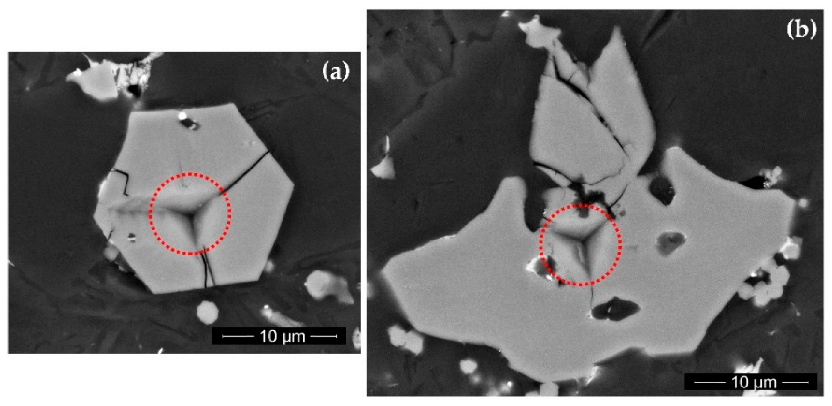
  • The microstructure reveals primary α-Fe particles with star-like and polyhedral morphologies. At higher Fe:Mn ratio, needle-like β-Fe phase appears too.
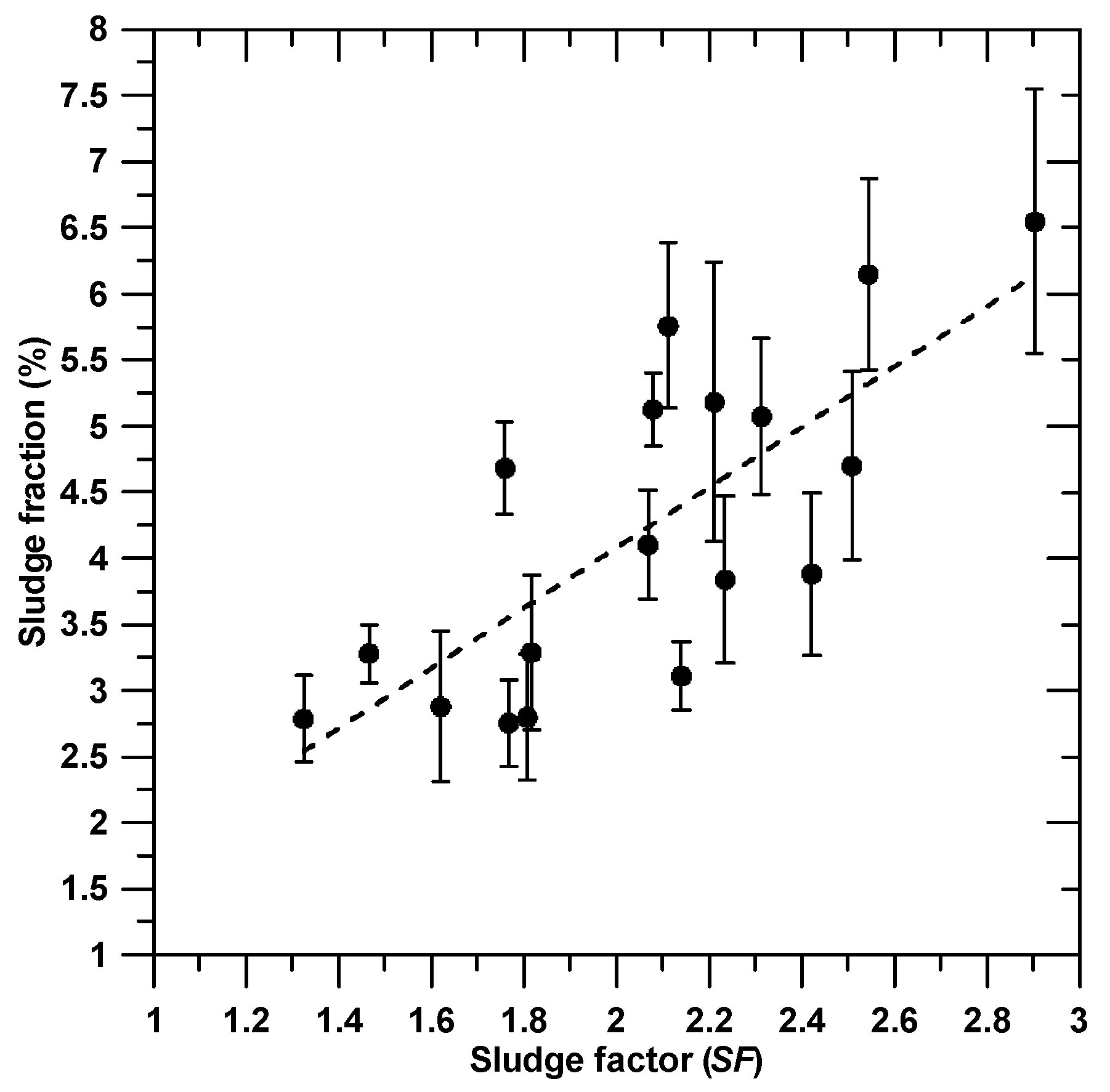
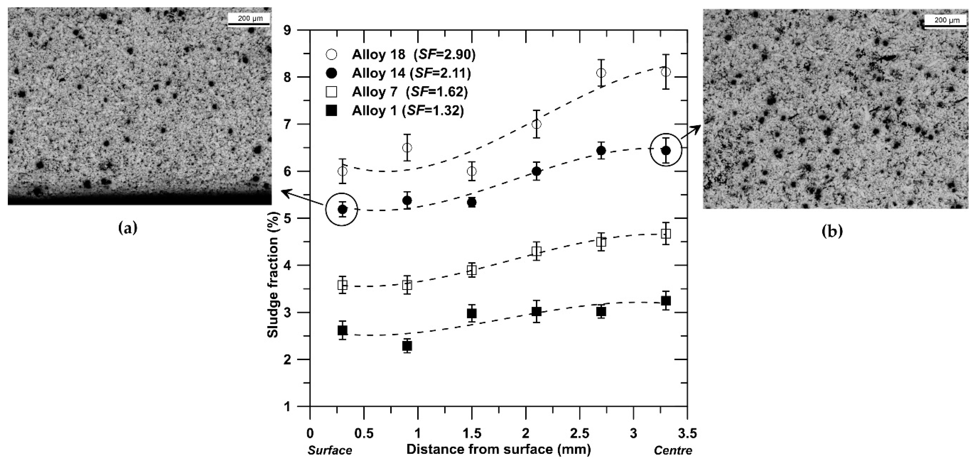
  • The contents of primary Fe-rich compounds (sludge), as well as secondary Fe-rich particles, increase by increasing the Fe, Mn, and Cr contents in the alloy.
  • Sludge particles show high hardness and reduced modulus, which are not affected by the initial contents of Fe, Mn, and Cr in the alloy; in addition, the different sludge morphology does not cause any variation in the hardness behavior.
  • At high temperatures, the experimental AlSi9Cu3(Fe) alloys show lower average hardness, especially at 200 °C; however, greater sludge fraction leads to higher hardness values.
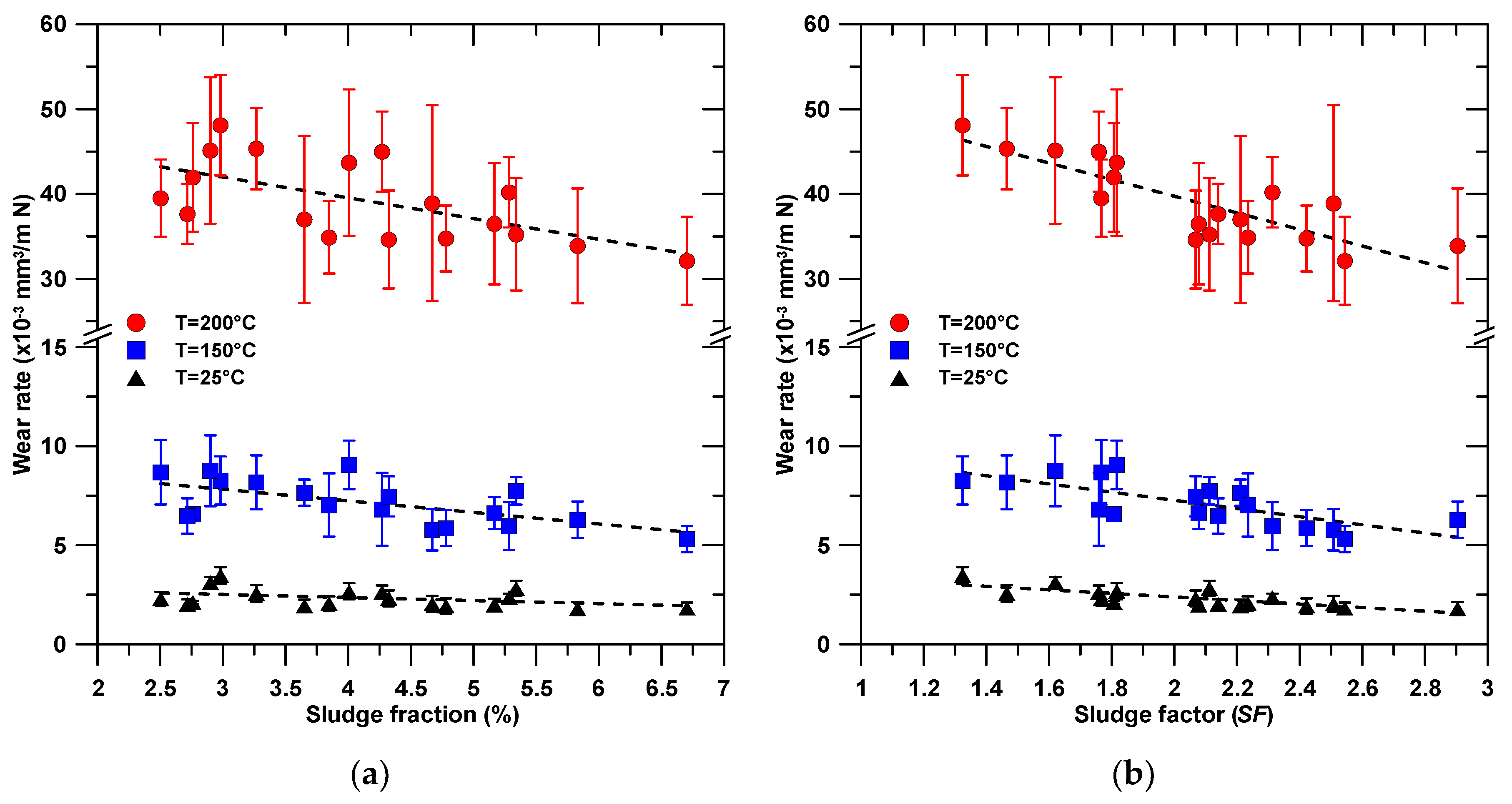
  • The wear rate decreases progressively with the amount of sludge particles, and this behavior is even more pronounced by increasing the temperature during testing. This feature is correlated to the hardening effect of the α-Fe phase that helps the Al-matrix to support the load.

Author Contributions

All the authors actively participated to the research: conceptualization, G.T.; methodology, G.T. and A.F.; software, A.D.M.; validation, G.T.; investigation, A.F., S.V., A.D.M.; formal analysis, G.T. and A.D.M.; resources, G.T. and S.V.; data curation, G.T.; writing, G.T.; writing—review and editing, A.F., S.V. and A.D.M.; supervision, G.T.; project administration, G.T.; funding acquisition, G.T. All authors have read and agreed to the published version of the manuscript.

Funding

This research was funded by the European Project NADIA (New Automotive components Designed for and manufactured by Intelligent processing of light Alloys) NMP-2004-SME 3.4.4.5, contract n.026563-2.

Acknowledgments

The authors would like to acknowledge the skilful contribution of Toolcast Snc (Brugine, Italy) and Raffineria Metalli Capra Spa (Brescia, Italy). Nicola Zavarise and Stefano Farronato are also acknowledged for the experimental contribution to this research.

Conflicts of Interest

The authors declare no conflict of interest.

References

  1. Rajaram, G.; Kumaran, S.; Srinivasa Rao, T. High temperature tensile and wear behaviour of aluminum silicon alloy. Mater. Sci. Eng. A 2010, 528, 247–253. [Google Scholar] [CrossRef]
  2. Slattery, B.E.; Perry, T.; Edrisya, A. Microstructural evolution of a eutectic Al-Si engine subjected to severe running conditions. Mater. Sci. Eng. A 2009, 512, 76–81. [Google Scholar] [CrossRef]
  3. Slattery, B.E.; Edrisya, A.; Perry, T. Investigation of wear induced surface and subsurface deformation in a linerless Al-Si engine. Wear 2010, 269, 298–309. [Google Scholar] [CrossRef]
  4. Abouei, V.; Saghafian, H.; Shabestari, S.G.; Zarghami, M. Effect of Fe-rich intermetallics on the wear behavior of eutectic Al-Si piston alloy (LM13). Mater. Design 2010, 31, 3518–3524. [Google Scholar] [CrossRef]
  5. Zhang, J.; Alpas, A.T. Transition between mild and severe wear in aluminium alloys. Acta Mater. 1997, 45, 513–528. [Google Scholar] [CrossRef]
  6. Pauschitz, A.; Roy, M.; Franek, F. Mechanisms of sliding wear of metals and alloys at elevated temperatures. Tribol. Int. 2008, 41, 584–602. [Google Scholar] [CrossRef]
  7. Culliton, D.; Betts, A.J.; Kennedy, D. Impact of intermetallic precipitates on the tribological and/or corrosion performance of cast aluminium alloys: a short review. Int. J. Cast Metal. Res. 2013, 26, 65–71. [Google Scholar] [CrossRef] [Green Version]
  8. Lee, K.Y.; Lee, S.L.; Wu, C.T.; Chen, W.C.; Lin, J.C. Effects of T6 heat treatment on thermal stability and wear behaviour of Al-12.5Si-4.5Cu-1.0Mg alloy. Mater. Sci. Technol. 2012, 28, 639–643. [Google Scholar] [CrossRef]
  9. Tomida, S.; Nakata, K.; Shibata, S.; Zenkouji, I.; Saji, S. Improvement in wear resistance of hyper-eutectic Al-Si cast alloy by laser surface remelting. Surf. Coat. Tech. 2003, 169–170, 468–471. [Google Scholar] [CrossRef]
  10. Taghiabadi, R.; Ghasemi, H.M.; Shabestari, S.G. Effect of iron-rich intermetallics on the sliding wear behaviour of Al-Si alloys. Mater. Sci. Eng. A 2008, 490, 162–170. [Google Scholar] [CrossRef]
  11. Makhlouf, M.M.; Apelian, D.; Wang, L. Microstructure and Properties of Aluminium Die Casting Alloys, 1st ed.; North American Die Casting Association: Rosemont, IL, USA, 1998. [Google Scholar]
  12. Dhiman, M.; Dwivedi, D.K.; Sehgal, R.; Bhat, I.K. Effect of iron (wt.%) on adhesive wear response of Al-12Si-1Cu-0.1Mg alloy in dry sliding conditions. Trans. Indian Inst. Met. 2008, 61, 451–456. [Google Scholar] [CrossRef]
  13. Cao, X.; Campbell, J. Morphology of β-Al5FeSi Phase in Al-Si Cast Alloys. Mater. Trans. 2006, 47, 1303–1312. [Google Scholar] [CrossRef] [Green Version]
  14. Mahta, M.; Emamy, M.; Cao, X.; Campbell, J. Overview of β-Al5FeSi Phase in Al-Si Alloys; Nova Science Publisher: New York, NY, USA, 2008; pp. 251–271. [Google Scholar]
  15. Timelli, G.; Fiorese, E. Methods to neutralize the effects of iron in Al-Si foundry alloys. Metall. Ital. 2011, 103, 9–23. [Google Scholar]
  16. Timelli, G.; Bonollo, F. The influence of Cr content on the microstructure and mechanical properties of AlSi9Cu3(Fe) die-casting alloys. Mater. Sci. Eng. A 2010, 528, 273–282. [Google Scholar] [CrossRef]
  17. Zahedi, H.; Emamy, M.; Razaghian, A.; Mahta, M.; Campbell, J.; Tiryakioğlu, M. The effect of Fe-rich intermetallics on the weibull distribution of tensile properties in a cast Al-5 Pct Si-3 Pct Cu-1 Pct Fe-0.3 Pct Mg alloy. Metall. Mater. Trans. A 2007, 38, 659–670. [Google Scholar] [CrossRef]
  18. Timelli, G.; Capuzzi, S.; Fabrizi, A. Precipitation of primary Fe-rich compounds in secondary AlSi9Cu3(Fe) alloys. J. Therm. Anal. Calorim. 2016, 123, 249–262. [Google Scholar] [CrossRef]
  19. Bidmeshki, C.; Aboudei, V.; Saghafian, H.; Shabestari, S.G.; Noghani, M.T. Effect of Mn addition on Fe-rich intermetallics morphology and dry sliding wear investigation of hypereutectic Al-17.5%Si alloy. J. Mater. Res. Technol. 2016, 5, 250–258. [Google Scholar] [CrossRef] [Green Version]
  20. Cao, X.; Campbell, J. Effect of precipitation of primary intermetallic compounds on mechanical properties of cast Al-11.5Si-0.4Mg alloy. AFS Trans. 2000, 108, 391–400. [Google Scholar]
  21. Cao, X.; Campbell, J. The nucleation of Fe-rich phases on oxide films in Al-11.5Si-0.4Mg cast alloys. Metall. Mater. Trans. A 2003, 34, 1409–1420. [Google Scholar] [CrossRef]
  22. Gobrecht, J. Settling-out of Fe, Mn and Cr in Al-Si casting alloys. Giesserei 1975, 62, 263–266. [Google Scholar]
  23. Jorstad, J.L. Understanding sludge. Die Cast. Eng. 1986, 30, 30–36. [Google Scholar]
  24. Irish Standard, EN 1706:2010. Aluminium and Aluminium Alloys—Castings-Chemical Composition and Mechanical Properties; CEN–Comité Européen de Normalisation: Brussel, Belgium, 2007. [Google Scholar]
  25. Timelli, G.; Ferraro, S.; Grosselle, F.; Bonollo, F.; Voltazza, F.; Capra, L. Mechanical and microstructural characterization of diecast aluminium alloys. Metall. Ital. 2011, 103, 5–17. [Google Scholar]
  26. Timelli, G.; Grosselle, F.; Voltazza, F.; Della Corte, E. A new reference die for mechanical properties evaluation in diecasting, Part 1—Design and process optimization. In Proceedings of the 4th International Conference High Tech Die Casting (HTDC2008), Montichiari (BS), Italy, 9–10 April 2008; Italian Association of Metallurgy (AIM): Milan, Italy, 2008. [Google Scholar]
  27. ASTM E10-15a. Standard Test Method for Brinell Hardness of Metallic Materials; ASTM International: West Conshohocken, PA, USA, 2015. [Google Scholar]
  28. Oliver, W.C.; Pharr, G.M. An improved technique for determining hardness and elastic modulus using load and displacement sensing indentation experiments. J. Mater. Res. 1992, 7, 1564–1583. [Google Scholar] [CrossRef]
  29. Ferraro, S.; Fabrizi, A.; Timelli, G. Evolution of sludge particles in secondary die-cast aluminum alloys as function of Fe, Mn and Cr contents. Mater. Chem. Phys. 2015, 153, 168–179. [Google Scholar] [CrossRef]
  30. Flemings, M.C. Behavior of metal alloys in the semisolid state. Metall. Trans. A 1991, 22A, 957–981. [Google Scholar] [CrossRef]
  31. Bäckerud, L.; Chai, G.; Tamminen, J. Solidification Characteristics of Aluminum Alloys, 1st ed.; American Foundrymen’s Society Inc.: Des Plaines, IL, USA, 1990; Volume 2, pp. 201–204. [Google Scholar]
  32. Helenius, R.; Lohne, O.; Arnberg, L.; Laukli, H.I. The heat transfer during filling of a high-pressure die-casting shot sleeve. Mater. Sci. Eng. A 2005, 413-414, 52–55. [Google Scholar] [CrossRef]
  33. Guo, Z.-P.; Xiong, S.-M.; Liu, B.-C.; Li, M.; Allison, J. Effect of process parameters, casting thickness, and alloys on the interfacial heat-transfer coefficient in the high-pressure die-casting process. Metall. Mater. Trans. A 2008, 39A, 2896–2905. [Google Scholar] [CrossRef]
  34. Shabestari, S.G. The effect of iron and manganese on the formation of intermetallic compounds in aluminum-silicon alloys. Mater. Sci. Eng. A 2004, 383, 289–298. [Google Scholar] [CrossRef]
  35. Mondolfo, L.F. Aluminium Alloys: Structure and Properties; Butterworth-Heinemann: Oxford, UK, 1976. [Google Scholar]
  36. Fabrizi, A.; Ferraro, S.; Timelli, G. The influence of Fe, Mn and Cr additions on the formation of iron-rich intermetallic phases in an Al-Si die-casting alloy. In Shape Casting: 5th International Symposium 2014; Tiryakioğlu, M., Campbell, J., Byczynski, G., Eds.; Minerals, Metals and Materials Society: Warrendale, PA, USA, 2014; pp. 277–284. ISBN 9781118888186. [Google Scholar]
  37. Timelli, G.; Fabrizi, A.; Capuzzi, S.; Bonollo, F.; Ferraro, S. The role of Cr additions and Fe-rich compounds on microstructural features and impact toughness of AlSi9Cu3(Fe) diecasting alloys. Mater. Sci. Eng. A 2014, 603, 58–68. [Google Scholar] [CrossRef]
  38. Lombardi, A.; D’Elia, F.; Ravindran, C.; Murty, B.S.; MacKay, R. Analysis of the secondary phases in the microstructure of 319 type Al alloy engine blocks using electron microscopy and nanoindentation. Trans. Indian Inst. Met. 2011, 64, 7–11. [Google Scholar] [CrossRef]
  39. Chen, C.L.; Richter, A.; Thomson, R.C. Mechanical properties of intermetallic phases in multi-component Al-Si alloys using nanoindentation. Intermetallics 2010, 17, 634–641. [Google Scholar] [CrossRef]
  40. Fischer-Cripps, A.C. Nanoindentation, 3rd ed.; Springer: New York, NY, USA, 2011. [Google Scholar]
  41. Ferraro, S.; Timelli, G. Influence of sludge particles on the tensile properties of die-cast secondary aluminum alloys. Metall. Mater. Trans. B 2015, 46, 1022–1034. [Google Scholar] [CrossRef]
  42. Scott, G.D.; Shabel, B.S.; Morales, A. Aluminum alloy suitable for pistons. U.S. Patent 5162065 10 November 1992. [Google Scholar]
  43. Cho, Y.-H.; Joo, D.-H.; Kim, C.-H.; Lee, H.-C. The effect of alloy addition on the high temperature properties of over-aged Al-Si(CuNiMg) cast alloys. Mater. Sci. Forum 2006, 519–521, 461–466. [Google Scholar] [CrossRef]
  44. Qian, Z.; Liu, X.; Zhao, D.; Zhang, G. Effects of trace Mn addition on the elevated temperature tensile strength and microstructure of a low-iron Al–Si piston alloy. Mater. Lett. 2008, 62, 2146–2149. [Google Scholar] [CrossRef]
  45. Mayer, H.; Papakyriacou, M.; Zettl, B.; Vacic, S. Endurance limit and threshold stress intensity of die cast magnesium and aluminium alloys at elevated temperatures. Int. J. Fatigue 2005, 27, 1076–1088. [Google Scholar] [CrossRef]
  46. Rohatgi, P.K.; Riu, Y.; Ray, S. Friction, Lubrication and Wear Technology; American Society for Metals: Metals Park, OH, USA, 1992; p. 85. [Google Scholar]
  47. Mrówka-Nowotnik, G. The effect of intermetallics on the fracture mechanism in AlSi1MgMn alloy. J. Achiev. Mater. Manuf. Eng. 2008, 30, 35–42. [Google Scholar]
  48. Campbell, J. An overview of the effects of bifilms on the structure and properties of cast alloys. Metall. Mater. Trans. B 2006, 37B, 857–863. [Google Scholar] [CrossRef]
  49. Gariboldi, E.; Lemke, J.N.; Ozhoga-Maslovskaja, O.; Timelli, G.; Bonollo, F. High temperature behaviour of 46000, 46100, 47100 Al die cast parts. Metall. Ital. 2016, 108, 49–52. [Google Scholar]
  50. Wang, L.; He, Y.; Zhou, J.; Duszczyk, J. Effect of temperature on the frictional behaviour of an aluminium alloy sliding against steel during ball-on-disc tests. Tribol. Int. 2010, 43, 299–306. [Google Scholar] [CrossRef]
  51. Kamminga, J.D.; Janssen, G.C.A.M. Experimental discrimination of plowing friction and shear friction. Tribol. Lett. 2007, 25, 149–152. [Google Scholar] [CrossRef] [Green Version]
  52. Farhat, Z.N. Contribution of crystallographic texturing to the sliding friction behaviour of fcc and hcp metals. Wear 2001, 250, 401–408. [Google Scholar] [CrossRef]
Figure 1. Die cast plate showing the investigated location (dimensions in mm).
Metals 10 00055 g001
Figure 2. OM micrograph of diecast base alloy (Alloy 1).
Metals 10 00055 g002
Figure 3. SEM micrograph of base alloy; α1-Fe and α2-Fe particles are indicated.
Metals 10 00055 g003
Figure 4. Bright field TEM micrographs of diecast AlSi9Cu3(Fe) alloy (Alloy 1) showing precipitation in the α-Al matrix: (a) before thermal exposure; after 30 min at (b) 150 °C and (c) 200 °C.
Metals 10 00055 g004
Figure 5. Etched microstructure of (a) Alloy 1, SF = 1.32, (b) Alloy 13, SF = 1.82, (c) Alloy 15, SF = 2.21, and (d) Alloy 18, SF = 2.90; the Fe-rich particles appear dark.
Metals 10 00055 g005
Figure 6. Sludge area fraction as function of sludge factor, SF.
Metals 10 00055 g006
Figure 7. Evolution of the area fraction of sludge particles along the cross section of the plates die cast with different experimental alloys, here indicated with their sludge factor (SF), which was calculated according to Equation (1). The micrographs refer to (a) the casting surface and (b) the center of the plate (Alloy 14); the Fe-rich particles appear dark in the etched microstructures.
Metals 10 00055 g007
Figure 8. SEM images of nanoindentation impressions in (a) polyhedral and (b) star-like sludge particles.
Metals 10 00055 g008
Figure 9. Brinell hardness tendency as a function of the sludge factor, SF, in the diecast experimental AlSi9Cu3(Fe) alloys.
Metals 10 00055 g009
Figure 10. Average wear rate at different temperatures as function of (a) the sludge area fraction and (b) the sludge factor in the diecast experimental AlSi9Cu3(Fe) alloys.
Metals 10 00055 g010
Figure 11. Micrographs of fractured (a) α-Al15(Fe,Mn,Cr)3Si2 particle and (b) β-Al5FeSi platelet after wear testing.
Metals 10 00055 g011
Figure 12. Effects of Fe, Mn, and Cr additions and test temperature on the friction coefficient at constant sliding distance. Alloys 1 (SF = 1.32) and 18 (SF = 2.90) with the lowest and highest sludge factors are taken as references.
Metals 10 00055 g012
Table 1. Composition (wt.%) of the AlSi9Cu3(Fe) base alloy.
SiFeCuMgMnCrNiZnPbBiSnTiAl
8.400.722.430.190.220.0560.051.050.0920.0340.0330.037bal.
Table 2. Concentration (wt.%) of iron, manganese, and chromium in the experimental alloys. The sludge factors, SF, obtained according to Equation (1), are also given.
Alloy No.FeMnCrSF
1 *0.720.220.0561.32
20.720.220.1021.47
30.730.430.0611.77
40.710.390.1051.81
50.720.590.0582.07
60.720.560.1042.14
71.010.220.0571.62
81.030.220.0991.76
91.040.430.0592.08
101.050.430.1082.24
111.010.570.0562.31
121.010.570.0942.42
131.220.210.0551.82
141.380.220.0992.11
151.250.400.0542.21
161.390.430.1002.54
171.270.530.0562.51
181.420.590.1032.90
* Base alloy.
Table 3. Mechanical properties of sludge α1-Fe particles measured in three different experimental alloys; the values for the α-Al matrix are also given as reference.
AlloyHardness (GPa)Reduced modulus (GPa)
Alloy 110.1 ± 1.4154 ± 15
Alloy 1310.3 ± 1.3157 ± 14
Alloy 1810.7 ± 1.5156 ± 15
α-Al matrix1.1 ± 0.679 ± 30
Table 4. Hardness values of sludge particles with different morphology.
Sludge MorphologyHardness (GPa)
Polyhedral shape10.6 ± 1.5
Star-like shape10.8 ± 1.0
Table 5. Regression coefficients used to estimate the wear rate at different temperatures through Equation (2), by using the SF expression. The R2 and p-values are also reported.
CoefficientSF
Room Temperature150 °C200 °C
a−0.90−2.07−9.78
b4.1811.4059.30
R20.610.550.70
p-value0.00010.00010.006

