Abstract
Additive Manufacturing (AM) is becoming a more and more widespread technology. Its capability to produce complex geometries opens new design possibilities. Despite the big efforts made by the scientific community for improving the AM processes, this technology still has some limitations, mainly related to the achievable surface quality. It is known that AM technologies promote the formation of LACKS of fusion inside the material. In some cases, the external surfaces are finished with traditional machining. This is the case of AM-produced gears. While the grinding operation aims to reduce the surface roughness, the presence of porosities just below the surface of the wrought component, could lead, after grinding, to the exposure of those porosities leading to a pitted surface. This phenomenon is surely not beneficial in terms of structural resistance, but can help the lubrication promoting the clinging of the lubricant to the surface. The aim of this paper is to study this effect. Micro-Computer-Tomography (μ-CT) analyses were performed on a 17-4 PH Stainless Steel (SS) produced via Selective Laser Melting (SLM). The real geometry of the pores was reproduced virtually and analyzed by means of multiphase CFD analyses in the presence of centrifugal effects.
1. Introduction
Additive Manufacturing (AM) is an innovative manufacturing technology that relies on the melting and solidification of metal powder allowing to create the final shape of the object as a superposition of successive layers.
AM is particularly suitable to reduce the weight of the components exploiting the possibility to put material only where needed for structural purposes. Examples in this sense are available in different sectors ranging from the bio-medical prosthesis to the aerospace engines. Moreover, this technology has pushed forward the capability to insert internal sensors already during the manufacturing process. Furthermore, the possibility to reduce the mass of the components without affecting significantly their stiffness could also help in improving the Noise, Vibration, and Harshness (NVH) behavior by shifting the eigenfrequencies and the resonances far from the operating point of the system. This could be, for example, the case of gears where the mass can be significantly reduced with a reticular gear rim.
The first patent [1] related to AM can be traced back to 1951 [2]. However, only in the last decade this technology has experienced a great expansion [3]. Nowadays, several different AM technologies are available on the market. Among them, the most important are the Direct Deposition (DD) and the Power Bed (PB) ones [4]. PB technologies can be further sub-classified into Electron Beam Melting (BEM) and Selective Laser Melting (SLM) [5]. The latter is the one used in this study. The metal powder is locally fused by means of a laser. The materials produced by AM do not differ significantly from their traditional counterparts in terms of the chemical composition. However, the different production processes promote the formation of different microstructures that, in turn, affect the mechanical properties.
For this study, a 17-4PH Stainless Steel (SS) was selected. Previous researches by the author [6,7] and other scholars [8] were aimed at characterizing the mechanical performances of this steel.
The 17-4PH is a stainless steel having a good corrosion resistance and good mechanical strength thanks to the martensitic structure [9] guaranteed by the precipitation of fine Cu-rich face centered cubic phase. The SLM process promotes the formation of dendritic structures with body centered cubic martensite and 50% of reserved austenite. AM technologies are characterized by high solidification speeds, leading to a metastable austenite phase in the matrix. Internal and surface defects such as porosities, inclusions, and a high roughness in the as-build condition, can act as crack nucleation sites [10,11].
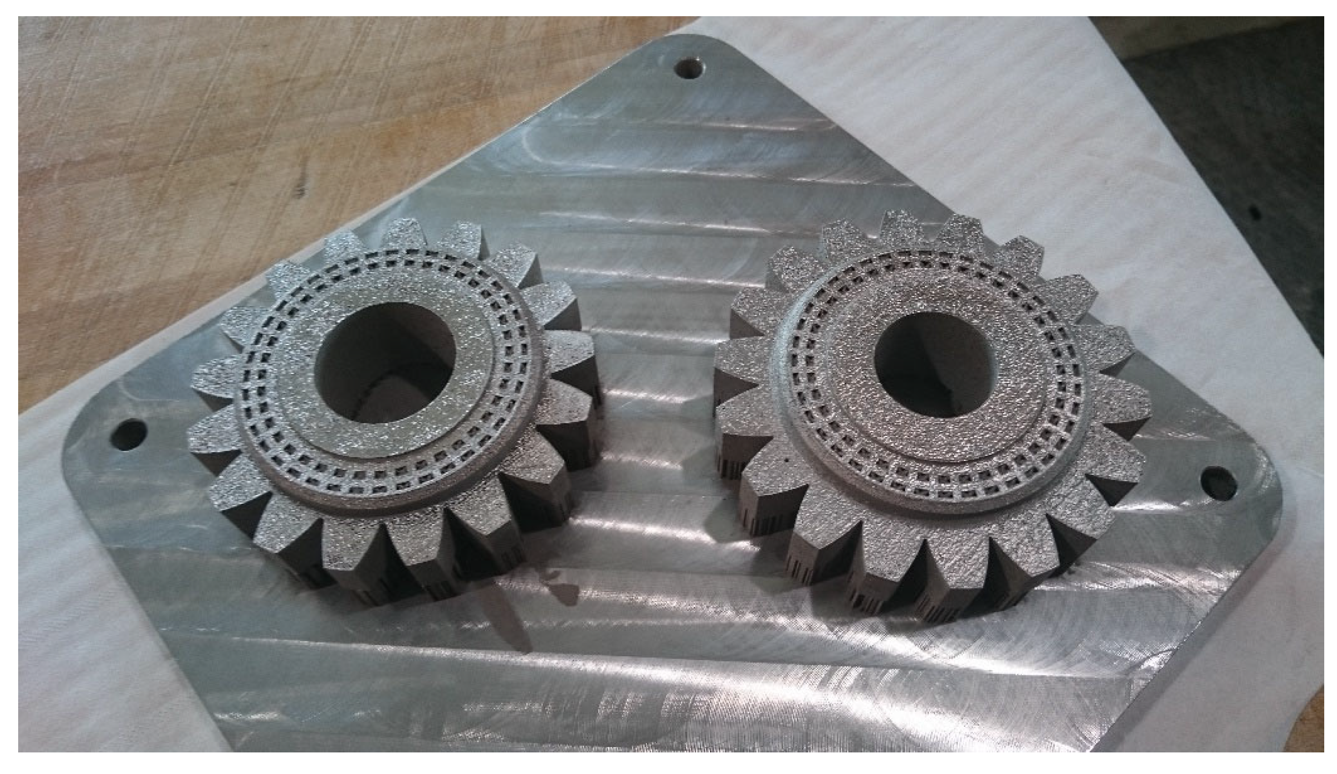
A high- and low-cycle fatigue testing campaign was carried out by the authors on AM produced 17-4PH SS both on standard samples [12,13,14] as well as on gears [15]. The results show that their fatigue properties are comparable with those of the wrought material. Starting from this consideration, the authors designed a gear pair having the standard FZG Type-C (FZG-C) geometry [16,17], in which the solid gear rim is substituted by a reticular structure. Considering that the gear rim normally has a significantly higher stiffness with respect to the gear teeth, a weight reduction is possible without significantly affecting the stiffness and strength of the component. By reducing the weight, the eigenfrequencies of the system are shifted to higher values and the Noise, Vibration, and Harshness (NVH) behavior of the gear train results are smoother. Figure 1 shows the lightweight gears produced by SLM.

Figure 1.
Lightweight gears produced by SLM.
However, the production of the reticular structure implies that also the gear teeth are manufactured via SLM. Their surface finishing as well as tolerances are not acceptable and far below the gear standards. Therefore, a grinding operation was performed on the flanks. Even the machining operations remove a thin layer of material, some sub-surface porosities emerge. The exposure of those porosities leads to a pitted surface. This is surely not desirable in terms of strength but can lead to significant benefits in terms of lubrication. At high speeds, in fact, the lubricant is thrown away by the centrifugal effects [18,19,20,21,22,23,24]. The teeth results are not wetted by the lubricant anymore. Therefore, a massive oil sump is required to allow the teeth to dive in the lubricant just before the meshing. The aim of this study is to quantify this effect based on real Micro Computer Tomography (μ-CT) measurements of the porosities.
2. Materials
The abovementioned gears were produced via SLM using an EOS M280 machine with bidirectional long scanning vectors rotating 90° between the successive layers.
The printing direction was aligned with the gear axis and performed in a Nitrogen gas filled chamber. The nominal power of the laser was 200 W. The spot diameter was equal to 100 µm and the layer thickness was 40 µm. The mean size of the powder particles was 44.454 µm. The chemical composition of the metal powder (declared by the manufacturer) is shown in Table 1.

Table 1.
Chemical composition of the metal powder.
Chromium interacts with carbon, forming chromium carbides along grains [20].
To prevent the creation of Cr23C6 and to increase strength, niobium is used. Si decreases the mechanical properties leading to the formation of ferric phase, but it is needed for fluidizing the material during the casting. To compensate this effect, Cr and Ni are used to reduce the formation of ferrite in favor of austenite. Ni and Mn are helpful to avoid the formation of Cr23C6 and FeS phases, respectively, forming Cr2N and MnS instead. Cu helps increase the total strength of the material forming precipitates.
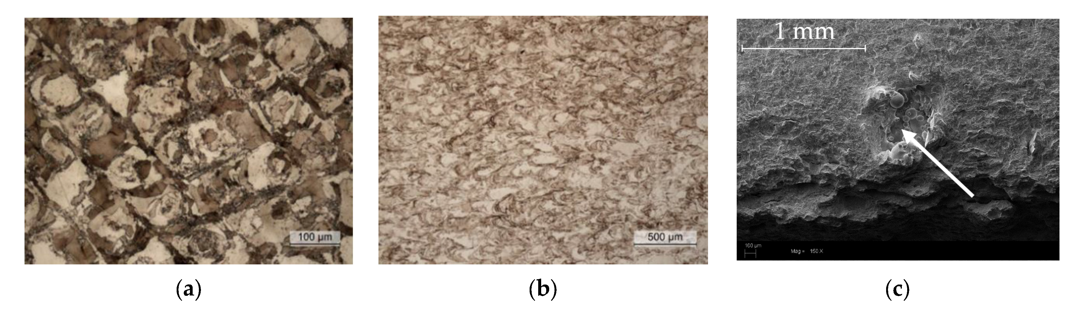
In addition to the gears, small cylindrical samples were produced for the μ-CT analyses. The cylinders were produced using the same manufacturing parameters used for the gear production. The need for having small samples is related to the μ-CT technique whose penetration capability is limited to few millimeters. The preliminary Optical Microscopy (OM) and the Scanning Electron Microscopy (SEM) measurements have pointed out the presence of porosities up to 100 µm (Figure 2). The chemical composition of the melt pools was investigated by the Energy-Dispersive X-ray Spectroscopy (EDS) analysis. No appreciable difference was detected among the pool center and boundaries: Al (0.28–0.30%), Si (0.47–0.51%), Cr (17.1–17.4%), Fe (73,15–74.6%), Ni (3.76–3.79%), Cu (3.27–3.30%), and Nb (0.24–0.25%).
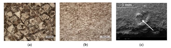
Figure 2.
OM: Melt pools in the transversal (a) and in the build (b) directions; SEM: Defect in LACKS of fusion (c).
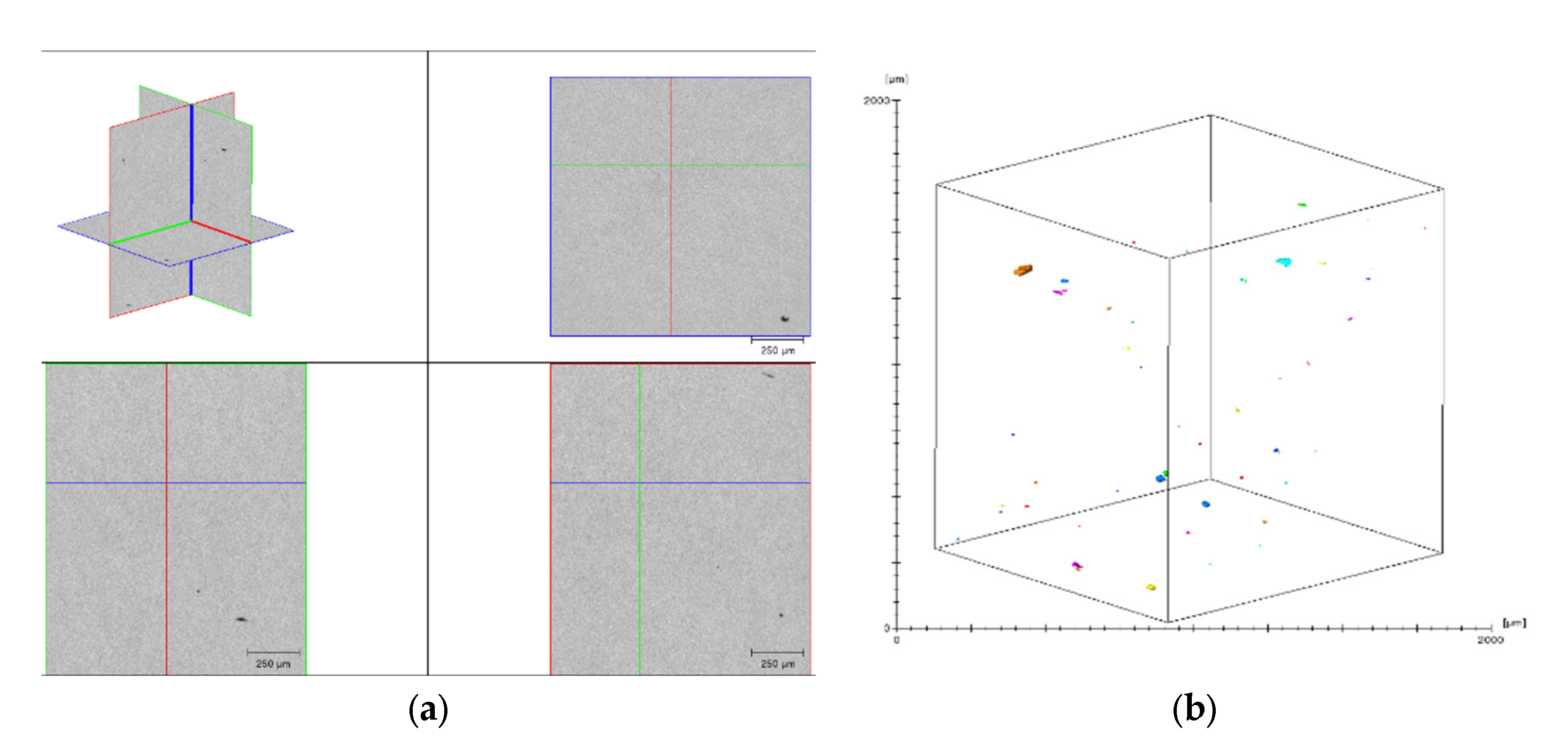
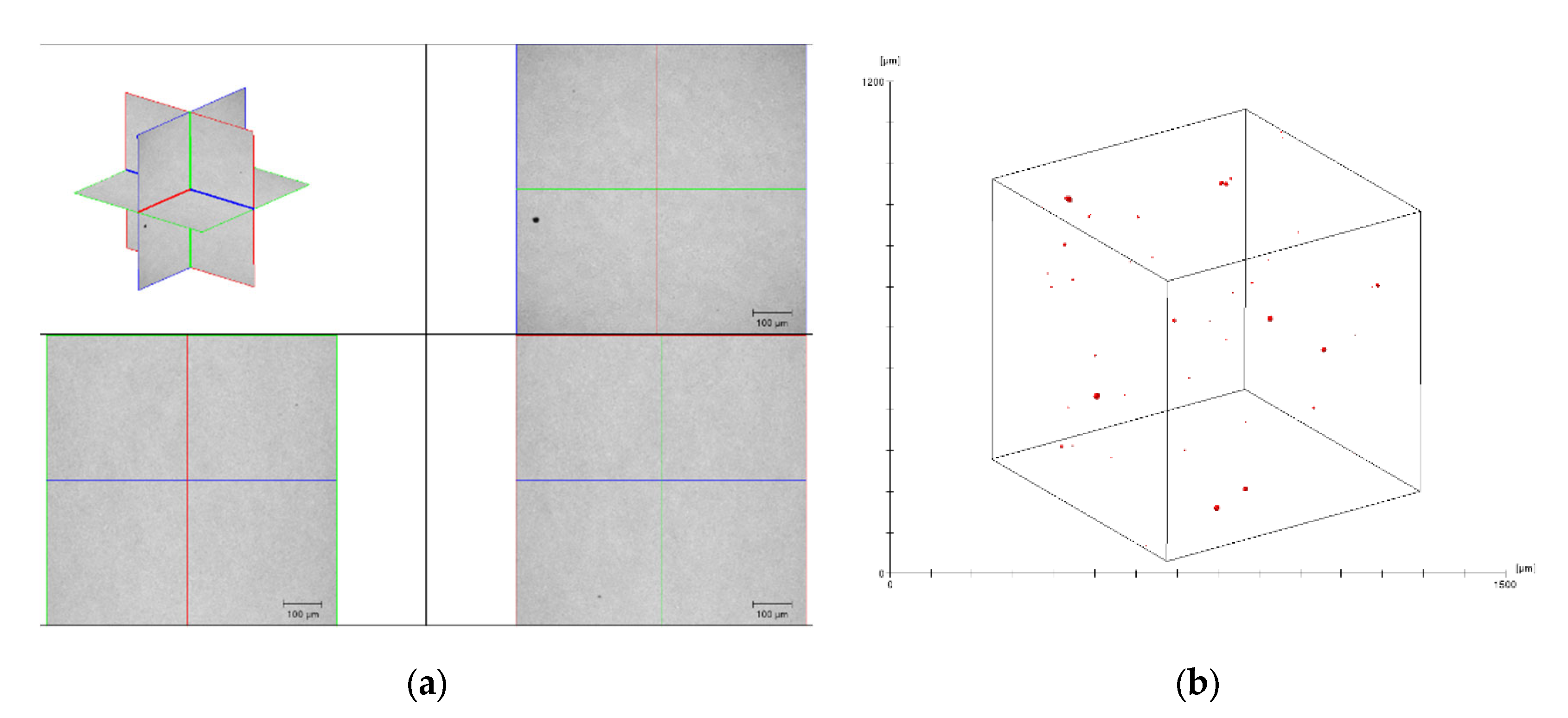
The μ-CT measurements were performed by the University of Kassel. A first scan was made with an effective pixel size of about 2.25 µm (Scouting—Figure 3), while a second scan was performed with a pixel size of about 1.125 µm (Zoom—Figure 4). Figure 3a and Figure 4a show the orthogonal views, while Figure 3b and Figure 4b show the distribution of the pores in the scanned volume.
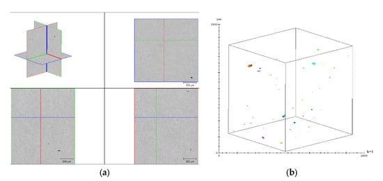
Figure 3.
Scouting scan: 2.25 μm. (a) Orthogonal views; (b) distribution of the pores in the scanned volume.
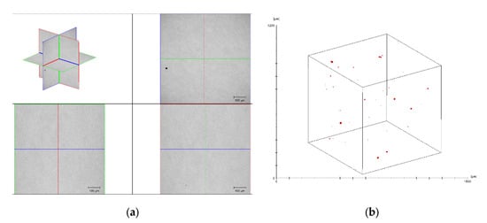
Figure 4.
Zoom scan: 1.125 μm. (a) Orthogonal views; (b) distribution of the pores in the scanned volume.
The μ-CT analyses confirm the presence of very small defects below 100 µm.
Starting from these results, the exposure of a sub-surface pore after grinding was simulated numerically. Considering that a grinding operation removes typically between 0.001 and 0.2 mm, each of the porosities within the measured volume can emerge after the finishing operation.
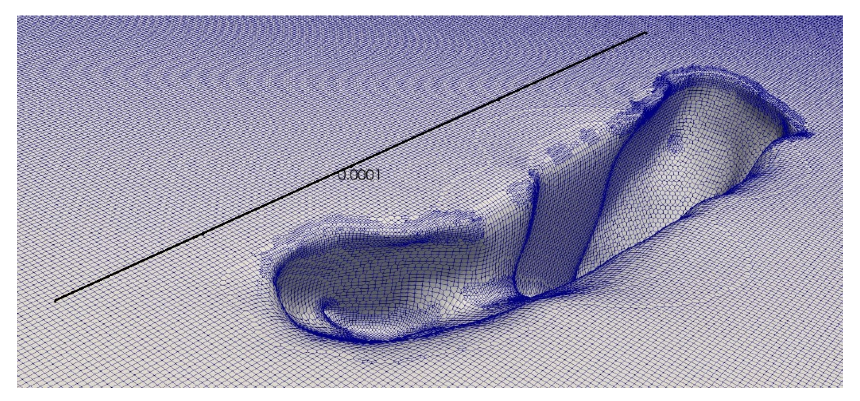
The biggest measured porosity (having a maximum length of about 100 μm and a volume of about 6 × 104 μm3) was virtually cut with a plane representing the tooth flank (Figure 5).

Figure 5.
Geometry of the emerged porosity considered in this study [m].
3. Configuration and Simulations
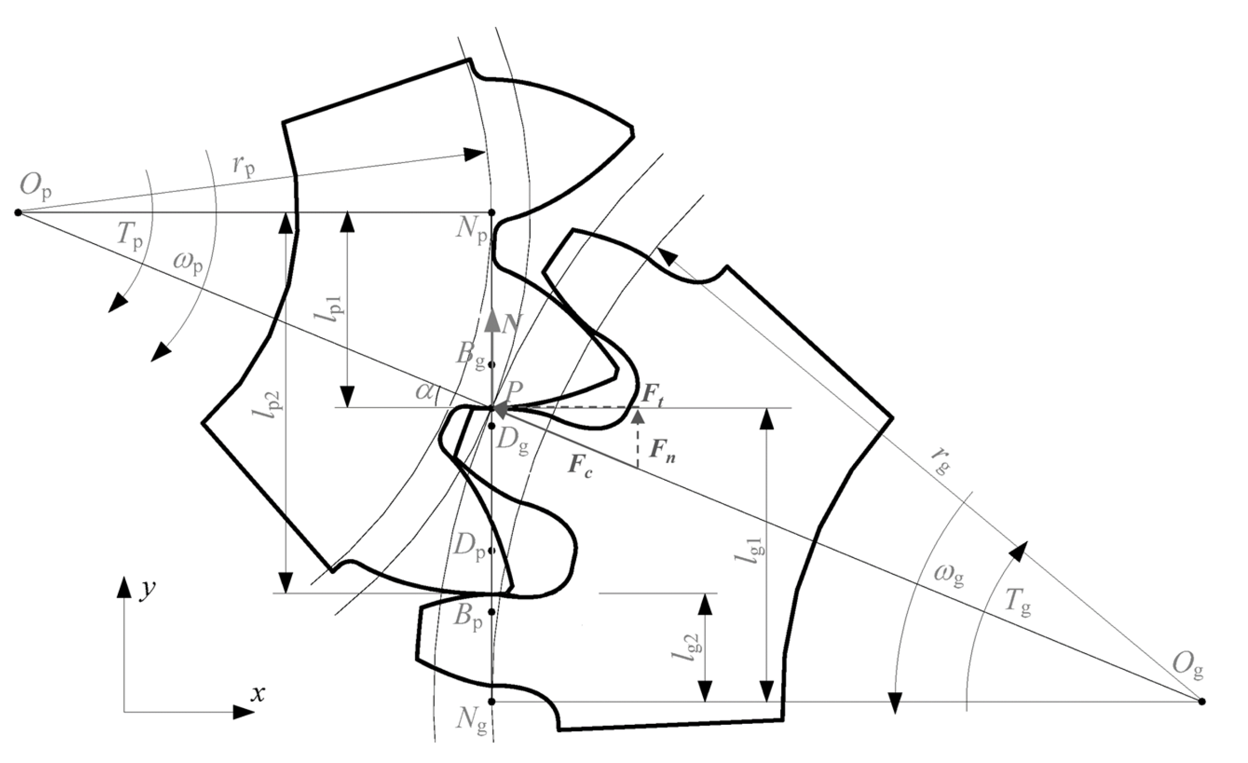
In order to study the centrifugal effects due to rotation on the lubrication, a surface representing a small portion of a teeth flank was modeled. As a reference, the geometry of the FZG-C gear type was selected. These gears are characterized by a pressure angle α of 20°. In the pitch point P (Figure 6), the relative angle between the flank’s normal N and the center distance Op-Og results in 90°.
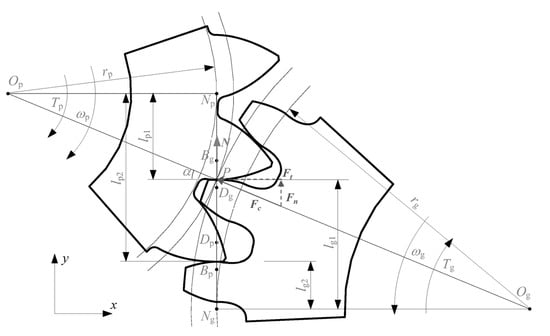
Figure 6.
Kinematics of a gear pair.
The angle between the direction of the centrifugal force Fc and the teeth flank is therefore α. The simulations were performed for different magnitudes of centrifugal accelerations, namely from 1 to 5000 g (g = 9.81 m/s2). Table 2 can help better quantify these accelerations. Considering that the standard FZG-C gear geometry [25] has a pitch radius rp of 45.75 mm [26], an acceleration of 5000 g (Table 2) corresponds to a tangential velocity vt of 47 m/s (ac = vt2/rp). These values are fully representative of the standard operating conditions of the FZG test rig [27], in which the tangential velocity usually ranges from 0 to 38.4 m/s [28].
Table 2.
Typical accelerations.
The lubricant considered is an FVA-3 which has a density of 824 kg/m3 and a viscosity of 29.8 mm2/s at 100 °C and 5.2 mm2/s at 40 °C. The surface tension is 0.023 N/m (Concli 2016).
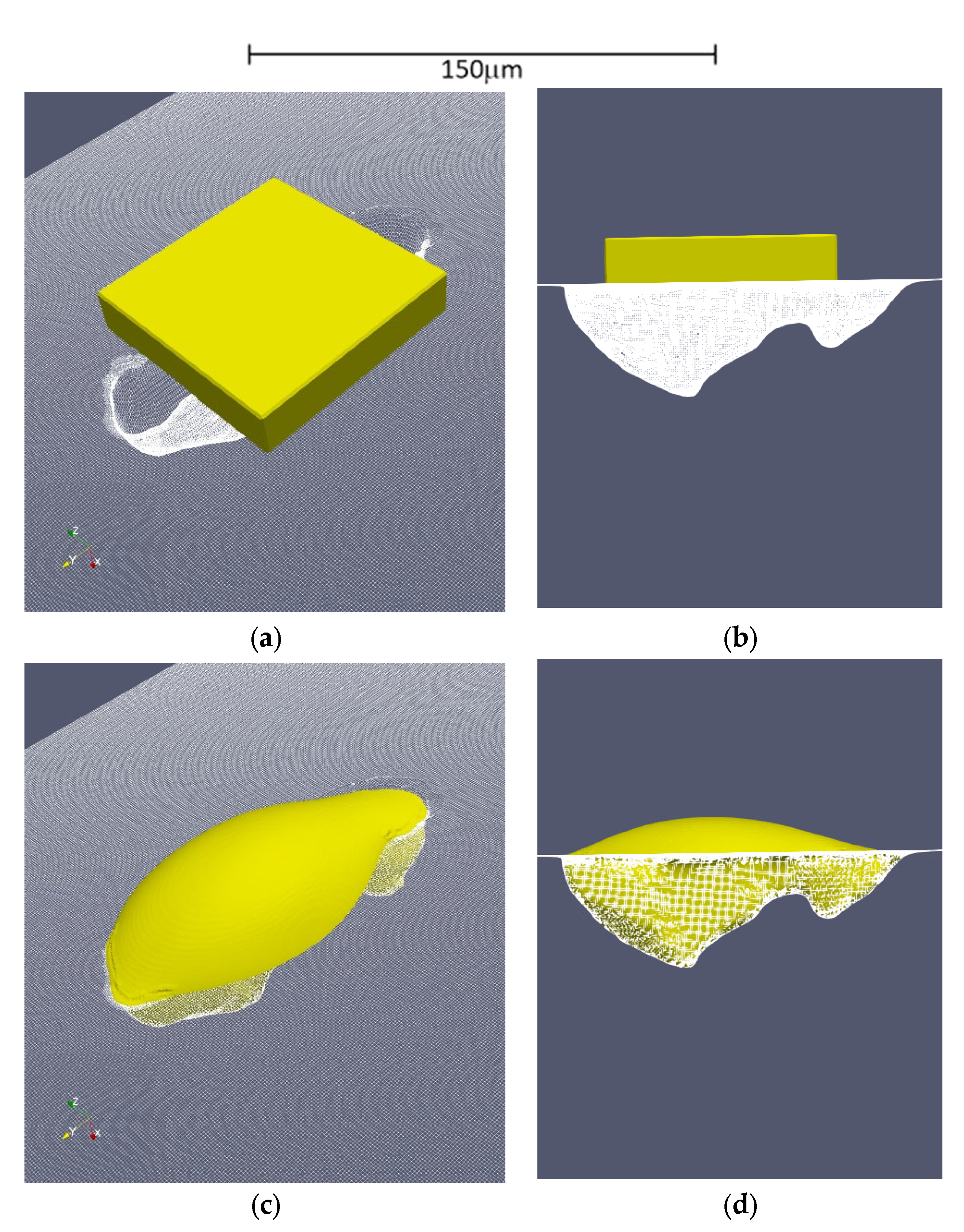
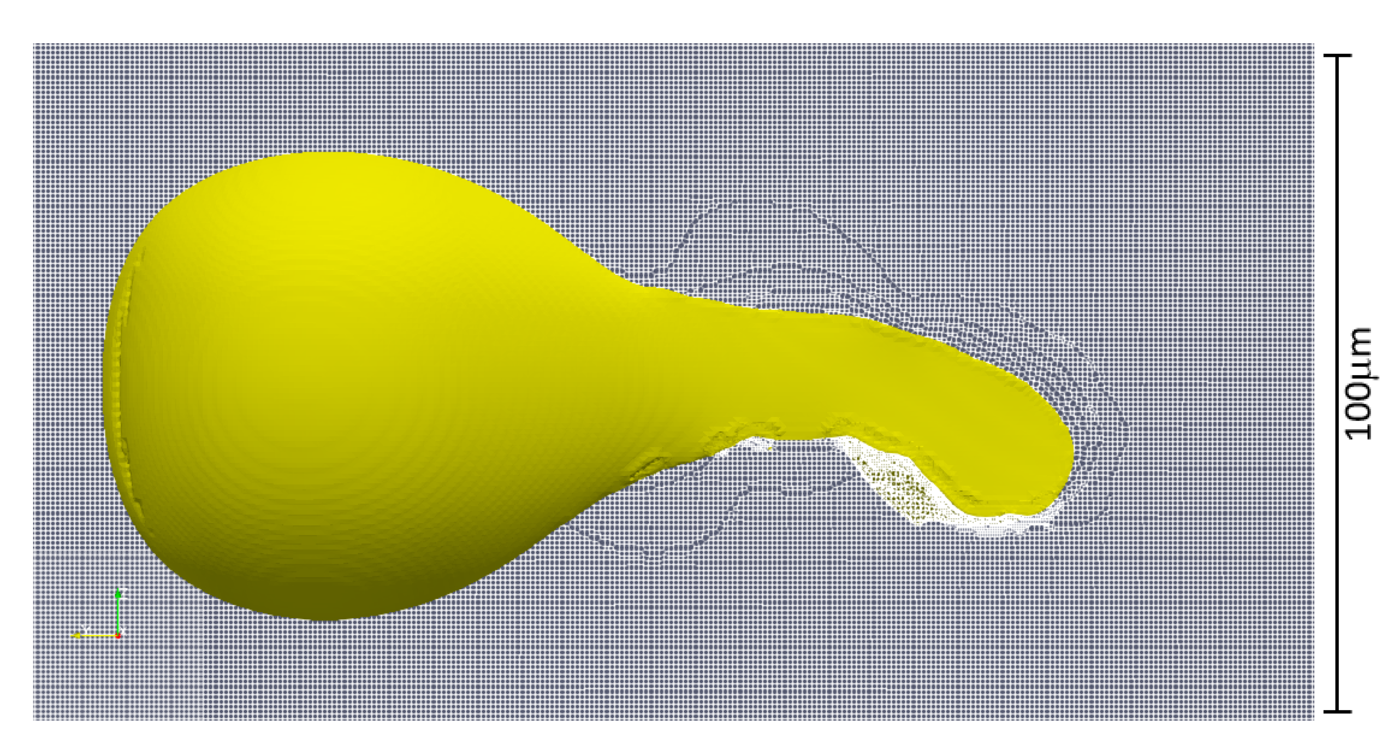
A droplet of oil having a volume of 2.5 × 10⁻⁵ mm3 (25 pl) was initially placed above the surface (Figure 7) (preconditioning stage). A preliminary simulation was performed in order to let the oil penetrate the cavity and reach the physical equilibrium (still standing condition). Thanks to the surface tension and a wetting angle of 45°, the oil fills the cavity as shown in Figure 7.

Figure 7.
Results of the preliminary simulation. The porosity is filled with 25 pl of oil; (a) isometric view, initial timestep; (b) lateral view, initial timestep; (c) isometric view, final timestep; (d) lateral view, final timestep.
The results of these preliminary simulations were used as a starting point for the successive analyses. The flank surface and cavity boundaries were modelled as walls (U = 0; ∇p = 0; ∇α = 0) and the remaining patches as free flow surfaces (∇U = 0; prel = 0; ∇α = 0). The only acting external force is the one due to the centrifugal acceleration. Its direction is inclined by an angle of 90°-αn (where αn = 20° is the pressure angle of the FZG-C gears) with respect to the surface normal.
Apart from the porosity, the surface of the gear was modelled as perfectly planar, and the roughness was neglected. The deformation of the solids under operation was neglected, as well.
The shape of the porosity was reconstructed with a 3.1 M cells grid with the average element size of 0.25 µm. The mesh was obtained using the standard OpenFOAM® [36,37] utilities blockMesh [38] and snappyHexMesh. While blockMesh is suitable to create simple meshes only—it decomposes the domain geometry into a set of 1 or more three dimensional, hexahedral blocks—snappyHexMesh is a fully parallel, split hex mesh generator that, starting from a background grid (generated with blockMesh), creates the final one by subtraction.
The adopted solver solves the Navier Stokes equations for two incompressible, isothermal immiscible fluids. The fluid properties are constant in the region filled by one of the two fluids except at the interphase. It relies on a constant-density continuity equation, a momentum equation, and an equation for the interphase.
where represents the velocity, the gravitational acceleration, the pressure, and and are the viscose and turbulent stresses. is the surface tension, modelled as a continuum surface force calculated on the basis of the curvature of the interface between the fluids. is the volume fraction. Density and viscosity are calculated, for each cell, based on the properties of the two fluids (namely the lubricant and the air) and the volume fraction alpha.
The flow was considered laminar and the unresolved Reynolds terms (namely and —the viscose and turbulent stresses) neglected (turbulence not activated).
The time step was selected dynamically to keep the courant number co below one in order to ensure the numerical stability. The average time step was equal to 1 × 10⁻⁸. A physical time of 2.5 × 10⁻³ s was simulated.
The simulations were performed on a Deploy Linux LXD [39] Computer Node [40] backed by 228 a Ceph storage cluster [41]. The LXD computer node is equipped with 2x INTEL Xeon® E5-2680 (8 Cores, 3.5 GHz) and 12 × 32 Gb ECC DIMMs Random-access memory. Each simulation took approximately 200 ks, corresponding to 2.3 days.
4. Results and Discussion
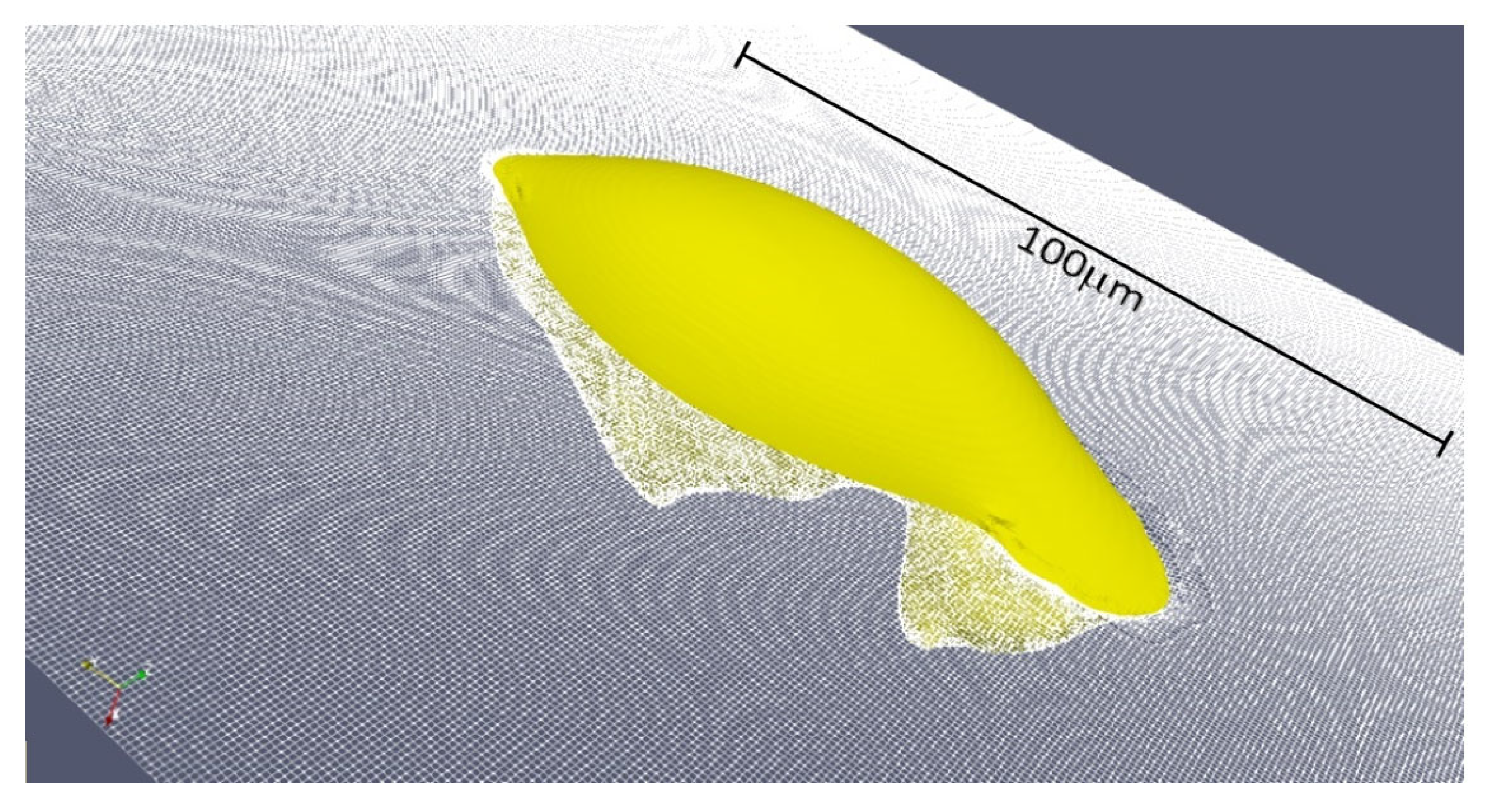
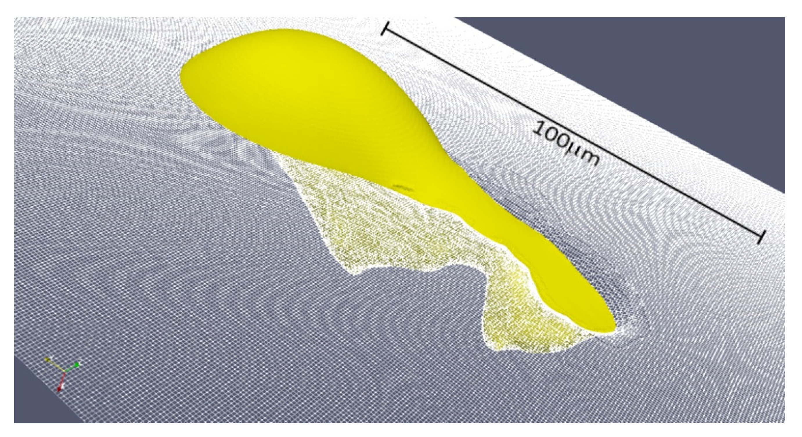
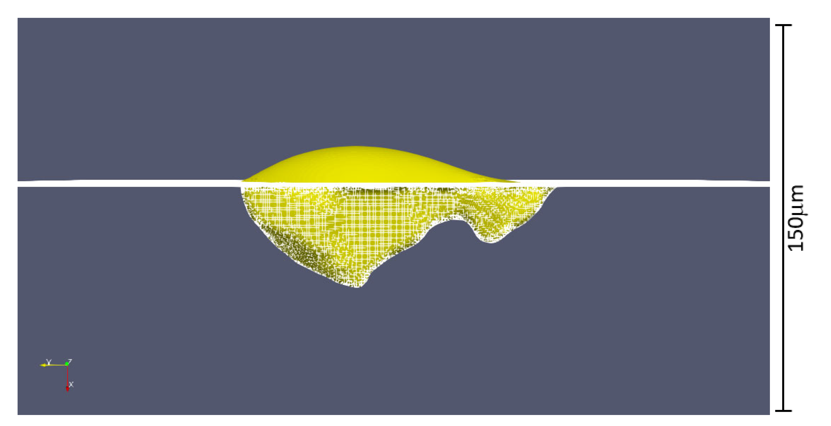
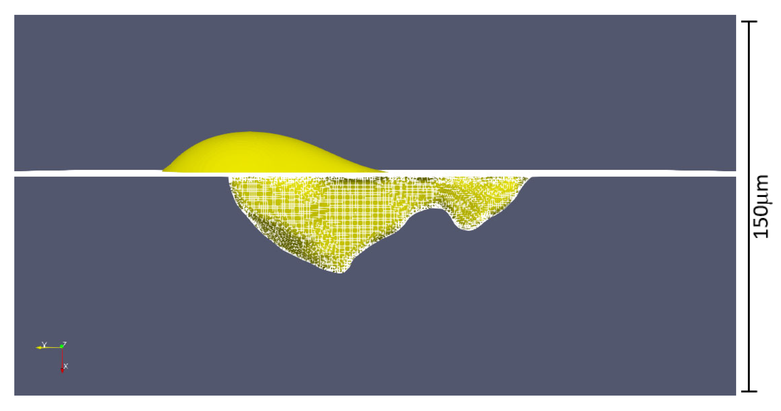
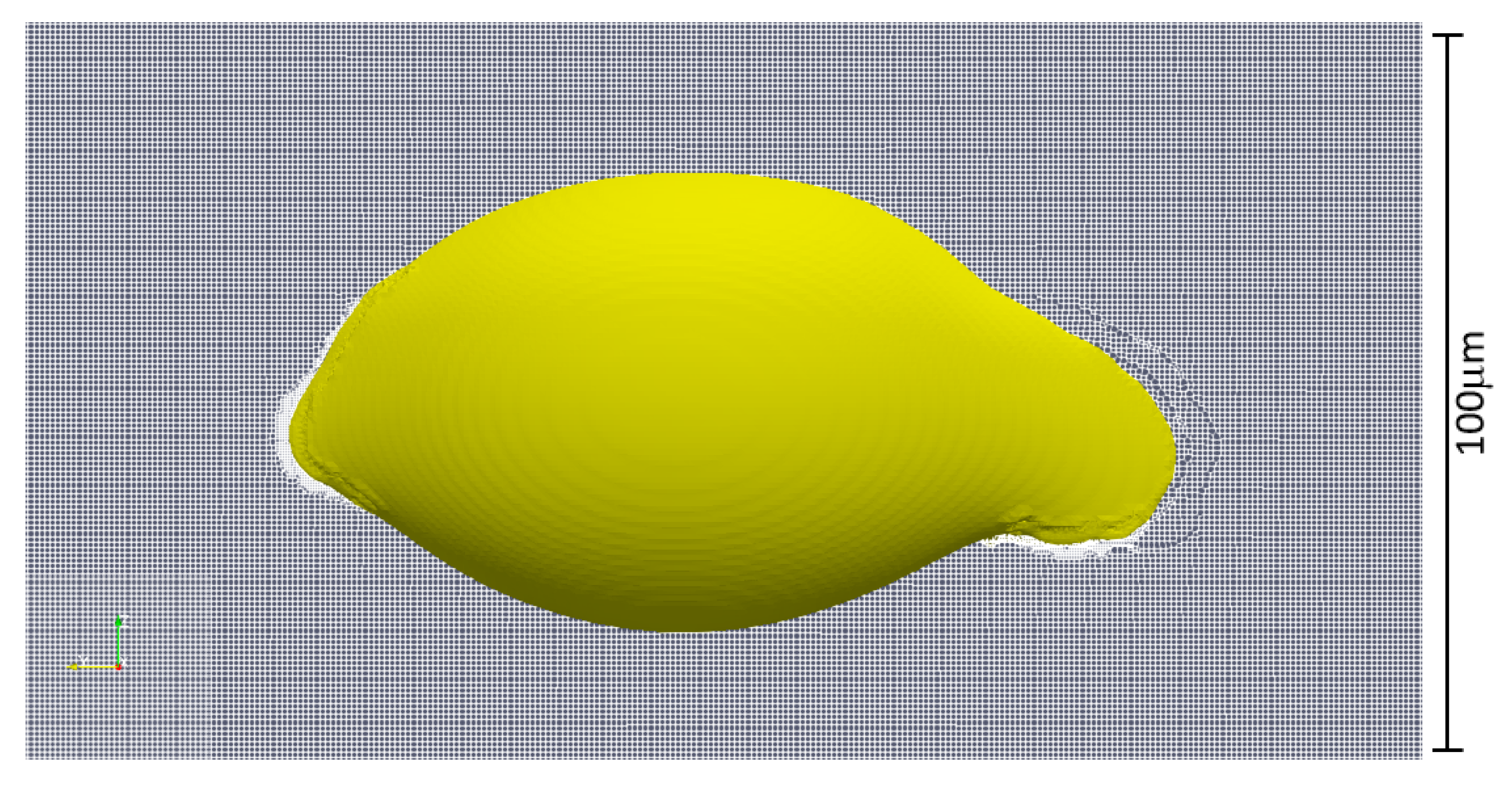
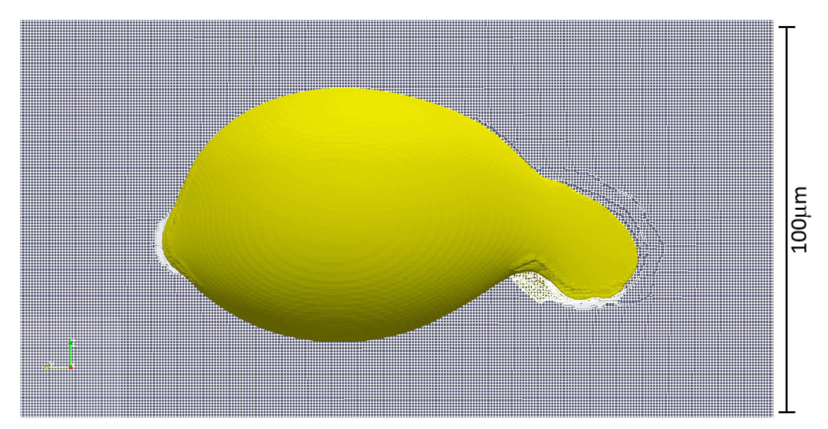
CFD simulations were run considering different values of centrifugal force, associated with tangential velocities of the gear between 21 to 47 m/s. The final equilibrium position of the oil droplet, undergone to the centrifugal force, was analyzed to investigate the adhesion enhancement related to the presence of the cavity. Figure 8, Figure 9, Figure 10, Figure 11, Figure 12, Figure 13, Figure 14, Figure 15 and Figure 16, show the final equilibrium position of the oil droplet. It can be noticed that up to tangential velocities of 30 m/s the oil seems to remain trapped into the cavity ensuring a good lubrication of the flank. On the other hand, at 47 m/s the centrifugal force becomes excessive, overcoming the surface tension which promotes the trapping of the droplet inside the cavity: The oil droplet firstly deforms and successively breaks due to high shear stresses. Neglecting the surface roughness, in the presence of a smooth surface without cavities, the oil flows on the surface already for very small velocities.

Figure 8.
Equilibrium position of the oil droplet for an acceleration of 1000 g corresponding, for an FZG-C gear, to a tangential speed vt of 21 m/s—isometric view.

Figure 9.
Equilibrium position of the oil droplet for an acceleration of 2000 g corresponding, for an FZG-C gear, to a tangential speed vt of 30 m/s—isometric view.

Figure 10.
Equilibrium position of the oil droplet for an acceleration of 5000 g corresponding, for an FZG-C gear, to a tangential speed vt of 47 m/s—isometric view.
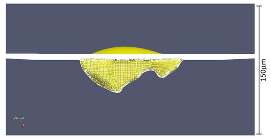
Figure 11.
Equilibrium position of the oil droplet for an acceleration of 1000 g corresponding, for an FZG-C gear, to a tangential speed vt of 21 m/s—lateral view.

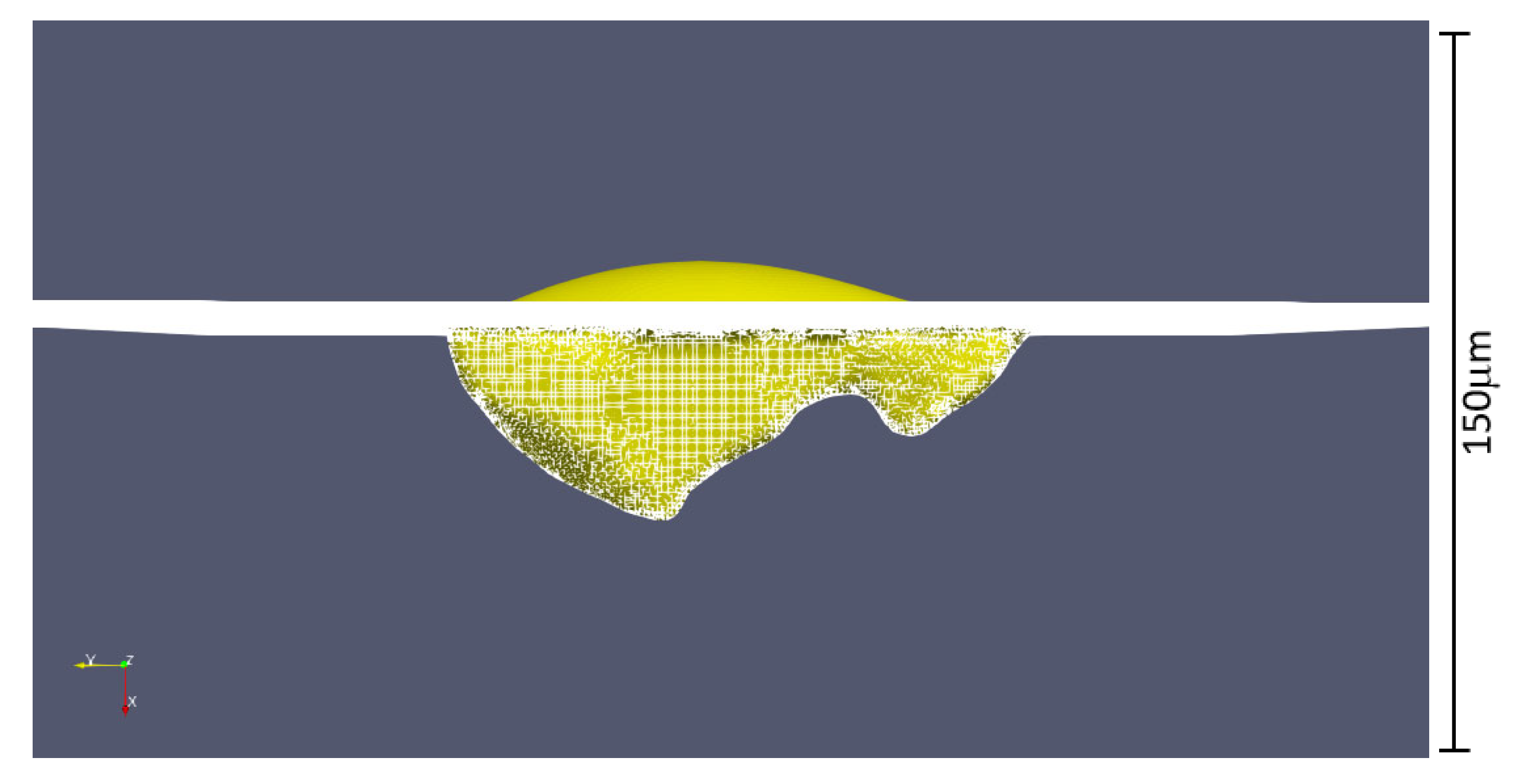
Figure 12.
Equilibrium position of the oil droplet for an acceleration of 2000 g corresponding, for an FZG-C gear, to a tangential speed vt of 30 m/s—lateral view.

Figure 13.
Equilibrium position of the oil droplet for an acceleration of 5000 g corresponding, for an FZG-C gear, to a tangential speed vt of 47 m/s—lateral view.
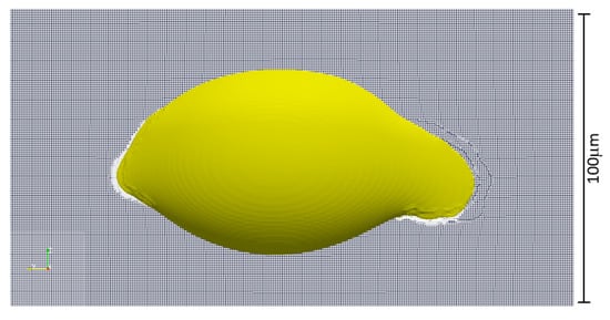
Figure 14.
Equilibrium position of the oil droplet for an acceleration of 1000 g corresponding, for an FZG-C gear, to a tangential speed vt of 21 m/s—top view.
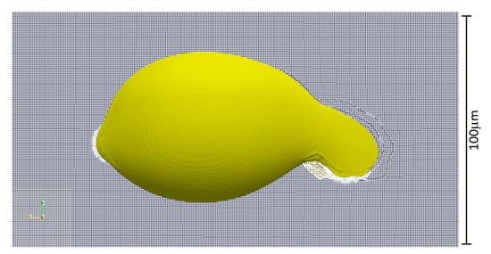
Figure 15.
Equilibrium position of the oil droplet for an acceleration of 2000 g corresponding, for an FZG-C gear, to a tangential speed vt of 30 m/s—top view.
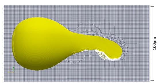
Figure 16.
Equilibrium position of the oil droplet for an acceleration of 5000 g corresponding, for an FZG-C gear, to a tangential speed vt of 47 m/s—top view.
Figure 17 reports the displacement of the top tip of the oil droplet for increasing values of the centrifugal force. Despite the fact that the deformation of the droplet becomes significant for the highest values, the clinging is maintained over all the operating conditions. This allows highlighting the beneficial effects of the small defects, eventually presenting on the surface of the AM flank, for the retention of the lubrication film.
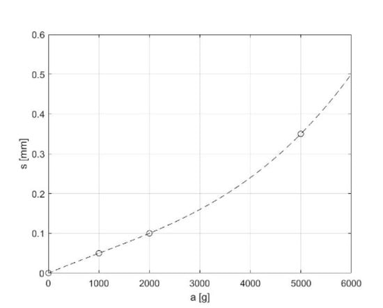
Figure 17.
Centrifugal acceleration vs. displacement of the top tip of the droplet.
While the specific detachment velocity depends on the shape of the pore as well as on the lubricant properties and should be evaluated for each specific configuration, the reported example points out the significant beneficial effect of having a jagged and not uniform surface. While in traditional machining the roughness of the surface could be limited with a proper selection of the manufacturing operations and their process parameters, in additive manufactured structures the final surface quality depends on whether the final machining is possible or not. In the latter case (for example, in the presence of reticula or lattice structures), the surface roughness is a consequence of the process parameters and is in general very high. This of course is not beneficial in terms of strength and crack nucleation but could lead to a better adhesion of the lubricant. On the other hand, when finishing operations are possible (such as in the presented test case), the final surface quality is mostly affected by the sub-superficial defects such as LACKS of fusion and pores. These kinds of porosities, after grinding, result in being exposed. The final surface appears therefore pitted. As in the case of high asperities resulting from rough machining, these porosities are very dangerous and significantly reduce the fatigue performances. On the other hand, the lubrication seems to be positively affected by such cavities.
In the present test case made of gears produced in 17-4 PH SS via SLM, the average sub-surface porosity was found to be in the order of magnitude of 10 to 100 microns. With a typical gear lubrication oil, namely an FVA-3 having a density of 824 kg/m3, a viscosity of 29.8 mm2/s at 100 °C and 5.2 mm2/s at 40 °C and a surface tension of 0.023 N/m, shows that the centrifugal acceleration required for the detachment of the oil droplet (end of lubrication) is of about 5000 g, a value comparable with the acceleration of the piston of a F1 car. This finding is important since it is one of the first evidence of a positive effect of the performances of the typical porosities of additive manufactured materials.
While an increase of the porosity reduces the mechanical strength, it could promote a good lubrication and possibly increase the wear and scuffing protection. In this regard, the right level of acceptable defects could be tuned to optimize the global performances of lubricated components and at the same time try to minimize the production costs without the need of necessarily achieving a zero-porosity product.
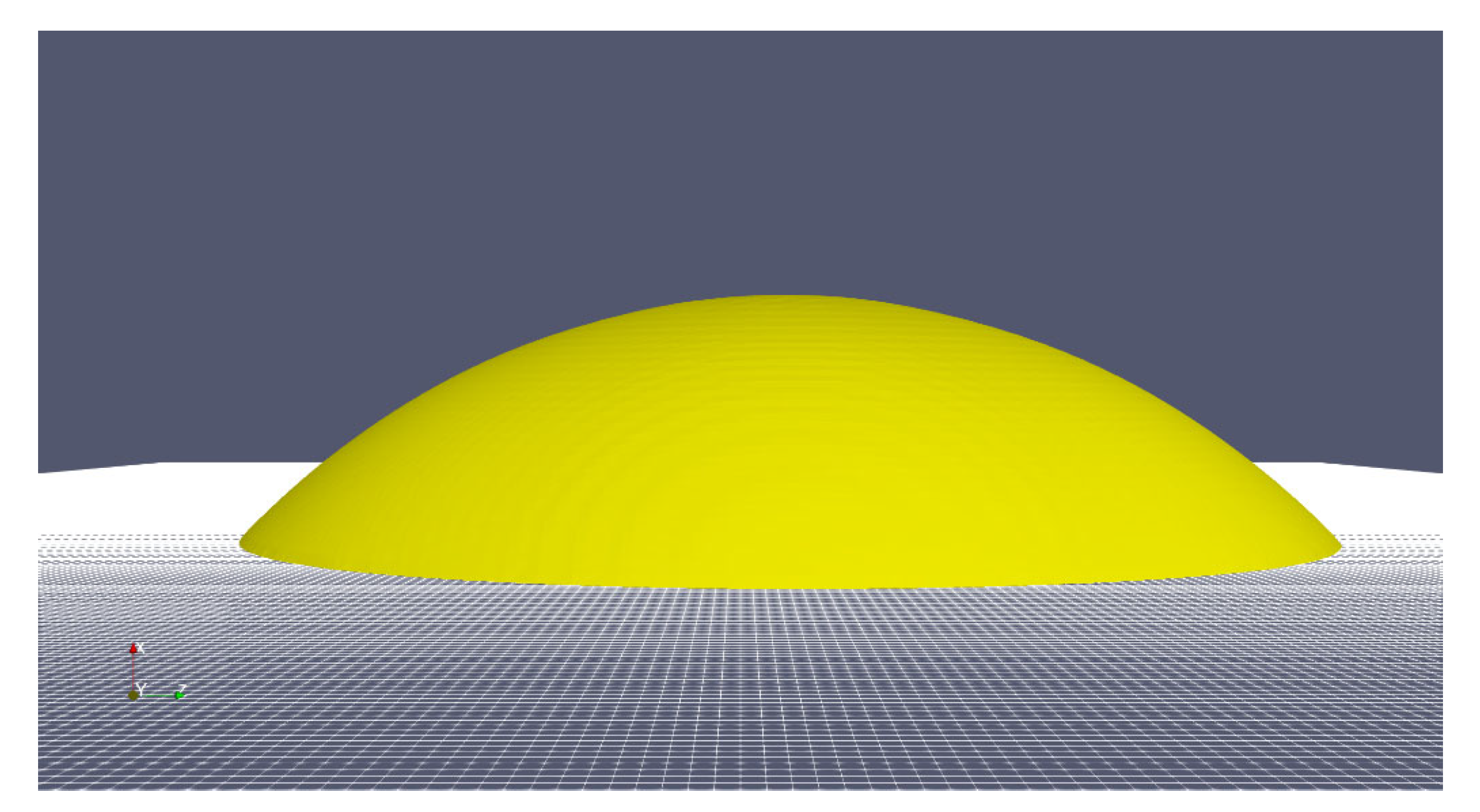
To report a practical example, let us consider a gearbox. The abovementioned evidence clarifies the different behaviors between the smooth surface and the one with exposed cavities as well as how these differences could affect lubrication. If the roughness is too small, in fact, the lubricant droplets could not cling to the surface (Figure 18). In this condition, to ensure the proper wetting of the contact between the gear flanks, significant amounts of lubricants should be used. In the presence of rotating elements such as gears, the splashing of the oil, namely churning, is usually enough to ensure a continuous oil supply to the meshing region. On the other hand, if the lubricant tends to remain on the flank surfaces despite the centrifugal effects, the required volume of oil could be reduced promoting a significant reduction in the load independent power losses (churning losses).
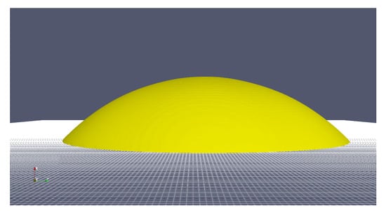
Figure 18.
Equilibrium position of the oil droplet for an acceleration of 1 g corresponding, for an FZG-C gear, to a tangential speed vt of 0.7 m/s—side view. The shape of the droplet remains hemispherical and the contact angle of 45° could be easily recognized.
5. Conclusions
In this work, a combination of micro-CT scans, OM and SEM analyses, and CFD simulations have been applied in order to investigate the impact of superficial defects of additive manufactured (AM) gears on the lubrication. In particular, the study was focused on a single defect on the surface, investigating the penetration of the oil droplet into the cavity, which promotes the clinging of the oil to the surface. The oil retention capability was evaluated considering the centrifugal forces acting on the lubrication film under typical operating conditions. The range of considered accelerations was selected according to the typical operating conditions of an FZG test rig, the standard equipment used for testing gears.
The results showed that superficial defects can improve the adhesion of the lubrication film, which is guaranteed even in the presence of significant centrifugal forces due to the rotation of the gear. This study, even if preliminary, highlights that the intrinsic high porosity of the AM components, if properly controlled, could be potentially exploited to provide superior properties to surface finishing, which could be beneficial for the lubrication.
Specifically, the present manufacturing process ensured a proper clinging of the oil droplets up to 5000 g, corresponding, for the FZG-C gears, to a rotational speed of about 1000 rads.
In the present research, the surface roughness was neglected, and only relatively big pores were considered. This choice was made to have a first clear differentiation between the perfectly smooth condition and a highly jagged profile. Considering the big differences observed, future studies are planned to better quantify the mutual effects of the presence of porosities (both in terms of size and topology) and roughness for different lubrications and operating conditions. Moreover, pitting- or wear-tests could possibly be used for an additional validation: An improved lubrication will increase the mechanical performance, which are easily measured.
Author Contributions
F.C. followed the experimental µ-CT measures, performed the CFD simulations, post-processed the results, and wrote the paper; A.D.T. supported the development of the CFD models and revised the paper. All authors have read and agreed to the published version of the manuscript.
Funding
This work was supported by the Open Access Publishing Fund of the Free University of Bozen-Bolzano.
Institutional Review Board Statement
Not applicable.
Informed Consent Statement
Not applicable.
Data Availability Statement
The datasets used and/or analyzed during the current study are available from the corresponding author on reasonable request.
Acknowledgments
The authors would like to thank the Free University of Bozen-Bolzano for the financial support given to this study through the projects M.AM.De (TN2092, call CRC2017 Unibz PI Franco Concli franco.concli@unibz.it) and APE (call RTD2021 Unibz PI Franco Concli franco.concli@unibz.it).
Conflicts of Interest
The authors declare that they have no competing interests.
References
- Munz, O.J. Photo-Glyph Recording. U.S. Patent 2,775,758A, 25 December 1956. [Google Scholar]
- Bourell, D.; Beaman, J.; Leu, M.; Rosen, D. RAPID History of AM and 2009 Roadmap. In Proceedings of the RapidTech 2009 US-TURKEY Workshop on Rapid Technologies, Istanbul, Turkey, 24 September 2009. [Google Scholar]
- Zhai, Y.; Lados, D.A.; Lagoy, J.L. Additive Manufacturing: Making imagination the major Limitation. JOM 2014, 66, 808–816. [Google Scholar] [CrossRef] [Green Version]
- Frazier, E.W. Metal additive manufacturing: A review. J. Mater. Eng. Perform. 2014, 23, 1917–1928. [Google Scholar] [CrossRef]
- Murr, L.E.; Gaytan, S.M.; Ramirez, D.A.; Martinez, E.; Hernandez, J.; Amato, K.N.; Shindo, P.W.; Medina, F.R.; Wicker, R.B. Metal Fabrication by Additive Manufacturing Using Laser and Electron Beam Melting Technologies. J. Mater. Sci. Technol. 2012, 28, 1–14. [Google Scholar] [CrossRef]
- Maccioni, L.; Fraccaroli, L.; Borgianni, Y.; Concli, F. High-Cycle-Fatigue Characterization of an Additive Manufacturing 17-4 PH Stainless Steel. In Proceedings of the 11th International Conference on Materials and Manufacturing Technologies, Bangkok, Thailand, 24–26 April 2020. MT013. [Google Scholar]
- Maccioni, L.; Rampazzo, E.; Nalli, F.; Borgianni, Y.; Concli, F. Low-Cycle-Fatigue Properties of a 17-4 PH Stainless Steel Manufactured via Selective Laser Melting. In Proceedings of the 11th International Conference on Materials and Manufacturing Technologies, Bangkok, Thailand, 24–26 April 2020. MT012. [Google Scholar]
- Mower, M.J.; Long, T.M. Mechanical behavior of additive manufactured, powder-bed laser-fused materials. Mater. Sci. Eng. A 2016, 651, 198–213. [Google Scholar] [CrossRef]
- Cheruvathur, S.; Lass, E.A.; Campbell, C.E. Additive Manufacturing of 17-4 PH Stainless Steel: Post-processing Heat Treatment to Achieve Uniform Reproducible Microstructure. JOM 2016, 68, 930–942. [Google Scholar] [CrossRef]
- Sehrt, G.J.; Witt, T. Dynamic Strength and Fracture Toughness Analysis of Beam Melted Parts. In Proceedings of the 36th International MATADOR Conference, Lancashire, UK, 14–16 July 2010. [Google Scholar]
- Yadollahi, A.; Shamsaei, N.; Thompson, S.M.; Elwany, A.; Bian, L. Mechanical and microstructural properties of selective laser melted 17-4 ph stainless steel. In Proceedings of the ASME International Mechanical Engineering Congress and Exposition, Proceedings (IMECE), Houston, TX, USA, 13–19 November 2015. 2A-2015. [Google Scholar]
- Facchini, L.; Vicente, N., Jr.; Lonardelli, I.; Magalini, E.; Robotti, P.; Alberto, M. Metastable austenite in 17-4 precipitation-hardening stainless steel produced by selective laser melting. Adv. Eng. Mater. 2010, 12, 184–188. [Google Scholar] [CrossRef]
- Wu, C.; Lin, J. Tensile and Fatigue Properties of 17-4 PH Stainless Steel at High Temperatures. Met. Mater. Trans. 2002, 33, 1717–1724. [Google Scholar] [CrossRef]
- Gu, H.; Gong, H.; Pal, D.; Rafi, K.; Starr, T.; Stucker, B. Influences of energy density on porosity and microstructure of selective laser melted 17-4PH stainless steel. In Proceedings of the 24th International SFF Symposium-An Additive Manufacturing Conference, SFF, Austin, TX, USA, 2–4 August 2013; pp. 474–489. [Google Scholar]
- Bonaiti, L.; Concli, F.; Gorla, C.; Rosa, F. Bending fatigue behaviour of 17-4 PH gears produced via selective laser melting. Procedia Struct. Integr. 2019, 24, 764–774. [Google Scholar] [CrossRef]
- Gorla, C.; Conrado, E.; Rosa, F.; Concli, F. Contact and bending fatigue behaviour of austempered ductile iron gears. Proc. Inst. Mech. Eng. Part C J. Mech. Eng. Sci. 2018, 232, 998–1008. [Google Scholar] [CrossRef]
- Concli, F. Austempered Ductile Iron (ADI) for gears: Contact and bending fatigue behavior. Procedia Struct. Integr. 2018, 8, 14–23. [Google Scholar] [CrossRef]
- Concli, F.; Gorla, C.; Torre, A.D.; Montenegro, G. Windage power losses of ordinary gears: Different CFD approaches aimed to the reduction of the computational effort. Lubricants 2014, 4, 162–176. [Google Scholar] [CrossRef]
- Peng, Q.; Zhou, C.; Gui, L.; Fan, Z. Investigation of the lubrication system in a vehicle axle: Optimization and experimental validation. Proc. Inst. Mech. Eng. Part D J. Automob. Eng. 2019, 233, 2096–2107. [Google Scholar] [CrossRef]
- Luke, P.; Olver, A.V. A study of churning losses in dip-lubricated spur gears. Proc. Inst. Mech. Eng. Part G J. Aerosp. Eng. 2019, 213, 337–345. [Google Scholar] [CrossRef]
- Seetharaman, S.; Kahraman, A.; Moorhead, M.D.; Petry-Johnson, T.T. Oil churning power losses of a gear pair: Experiments and model validation. J. Tribol. 2009, 131, 0222021–02220210. [Google Scholar] [CrossRef]
- Hill, M.J.; Kunz, R.F.; Medvitz, R.B.; Handschuh, R.F.; Long, L.N.; Noack, R.W.; Morris, P.J. CFD analysis of gear windage losses: Validation and parametric aerodynamic studies. J. Fluids Eng. Trans. ASME 2009, 133, 031103. [Google Scholar] [CrossRef] [Green Version]
- Kodela, C.; Kraetschmer, M.; Basa, S. Churning Loss Estimation for Manual Transmission Gear Box Using CFD. SAE Int. J. Passeng. Cars-Mech. Syst. 2015, 8, 391–397. [Google Scholar] [CrossRef]
- Hamlin, R.J. Microstructural Evolution and Mechanical Properties of Simulated Heat Affected Zones in Cast Precipitation Hardened Stainless Steels 17-4 and 13-8 + Mo. Metal. Mater. Trans. 2017, 48, 246–264. [Google Scholar] [CrossRef]
- Concli, F.; Gorla, C.; Stahl, K.; Höhn, B.-R.; Miachaelis, K.; Schultheiss, H. Stemplinger Load independent power losses of ordinary gears: Numerical and experimental analysis. In Proceedings of the 5th World Tribology Congress, WTC2013, Torino, Italy, 8–13 September 2013; Volume 2, pp. 1243–1246. [Google Scholar]
- Concli, F.; Gorla, C.; Rosa, F.; Conrado, E. Effect of the static pressure on the power dissipation of gearboxes. Lubr. Sci. 2019, 31, 347–355. [Google Scholar] [CrossRef]
- Höhn, B.-R.; Michaelis, K.; Otto, H.-P. Influence on no-load gear losses. In Proceedings of the ECOTRIB 2011: 3rd European Conference on Tribology in Tandem with Viennano ’11-4th Vienna International Conference on Nano-Technology, Wien, Austria, 7–9 June 2011; pp. 639–644. [Google Scholar]
- Concli, F.; Gorla, C. CFD simulation of power losses and lubricant flows in gearboxes. In Proceedings of the American Gear Manufacturers Association Fall Technical Meeting, Alexandria, VA, USA, 27 June 2017. [Google Scholar]
- Lilienfeld, S.O.; Arkowitz, H. Lunacy and the Full Moon. Sci. Am. Mind 2009, 20, 64–65. [Google Scholar] [CrossRef]
- Bugatti. Available online: https://assets.bugatti.com/ (accessed on 15 July 2019).
- Dennis, J.R. Space Shuttle: Developing an Icon–1972–2013; Specialty Press: Forest Lake, MN, USA, 2016. [Google Scholar]
- FORMULA 1. Available online: www.f1.com (accessed on 15 July 2019).
- FIA. Available online: www.fia.com (accessed on 15 July 2019).
- AUTO123. Available online: www.auto123.com (accessed on 15 July 2019).
- Lechome. Available online: www.lechom.com (accessed on 15 July 2019).
- Concli, F. Thermal and efficiency characterization of a low-backlash planetary gearbox: An integrated numerical-analytical prediction model and its experimental validation. Proc. Inst. Mech. Eng. Part J. J. Eng. Tribol. 2016, 230, 996–1005. [Google Scholar] [CrossRef]
- OpenFOAM. Available online: www.openfoam.com (accessed on 15 July 2019).
- Concli, F.; Schaefer, T.C.; Bohnert, C. Innovative Meshing Strategies for Bearing Lubrication Simulations. Lubricants 2020, 8, 46. [Google Scholar] [CrossRef] [Green Version]
- Linux Containers. Available online: https://linuxcontainers.org (accessed on 28 August 2019).
- Cisco. Available online: https://www.cisco.com/c/dam/en/us/products/collateral/servers-unified-computing/ucs-b-series-blade-servers/B200M3_SpecSheet.pdf (accessed on 30 August 2019).
- Ceph. Available online: https://ceph.com (accessed on 2 October 2019).


Publisher’s Note: MDPI stays neutral with regard to jurisdictional claims in published maps and institutional affiliations. |
© 2021 by the authors. Licensee MDPI, Basel, Switzerland. This article is an open access article distributed under the terms and conditions of the Creative Commons Attribution (CC BY) license (https://creativecommons.org/licenses/by/4.0/).