1. Introduction
One of the main systems in a modern vehicle powertrain based on manual or automated manual transmission is the frictional clutch system. As is well known, the friction clutch system accounts for more than one task, but the main one is the transmission of the power from the driving side (engine) to the driven side (gearbox). The other tasks are absorbing the vibration and engine torque irregularities, and providing smooth transition between different vehicle driving conditions.
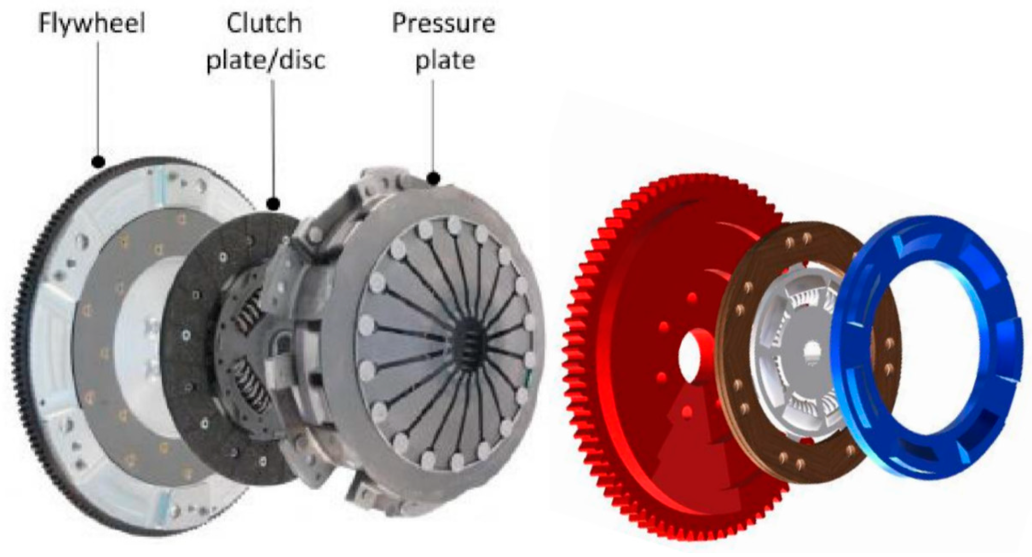
Figure 1 shows the main parts of a single disc dry clutch system.
Figure 2 shows the cycle engagement of the clutch system, which consists of two periods. In the first period, an axial force is applied to a pressure plate to produce sufficient compression to trigger the initial engagement. A significant disadvantage of this stage is the high amount of friction heat generation due to the sliding between rubbing surfaces [
1]. This period is called the heating period (slipping phase), this is also the phase characterized by the highest values of thermal stresses and interface temperature. Once both the parts of the system (driving and driven) reach the same speed, the heat generation vanishes and the second period starts (lock-up phase).
The friction clutch system is essentially based on the frictional states between two rotating elements in sliding contact. Overheating and bad cooling during the slipping phase could lead to drastic reduction of the performance and may cause premature failure of the contacting surfaces such as cracks, plastic deformation, etc.
Figure 3 shows the main variables influencing the thermo-mechanical behavior and ensuing performance of automotive clutches which have a potential occurrence of failure. Other parameters such as the degree of air cooling, the geometry of the contacting parts (i.e., thickness) and grooving profile are usually considered important issues in the design of clutches.
Al-Shabibi and Barber [
2] developed a new numerical approach of the whole sliding system, by assuming contact pressure profiles under different sliding speeds. The new feature of this mode is that it can be use it to find the critical speed of the system. These analyses could essentially be seen as virtualizing of experiment with the clear advantages of shorter time necessary for the development of new product is shorter, lower costs, and it allows also a better understanding of the problem because of the visualization of thermal and mechanical stresses. Moreover, it is possible in early stages of product development to detect the main influential variables as well as what is necessary to change or improve, in order to ensure the highest reliability of the observed elements [
3]. Such results have been obtained by Lee et al. [
4], where the main finding is the increase of pressure plate’s thickness to promote higher heat capacity, and reduce the thermal stresses. However, it is generally possible to determine the optimal working conditions of the friction clutch. Abdullah et al. [
5] investigated the effect of the applied pressure on the temperatures investigated, when the acting pressure is constant. Lower temperatures are obtained in the case of the linear pressure.
The frictional heat generated during the sliding of clutch system, assuming uniform wear, was investigated. The results obtained proved that the temperature field is uniform on facing surfaces [
6]. This is quite crucial for automotive engineers in order to find the optimal working conditions and to prolong the life cycle of the frictional clutch under design.
Liu et al. [
7] built two numerical models of multi-disc clutch based on the finite element method to study the contact and the thermodynamic problems. They investigated the effect of the material properties on the distribution of pressure for each disc in the system. They validated the numerical results with a static pressure test. Liu et al. [
8] also investigated thermo-dynamic characteristics for the multi-disc clutch. It was found that the elastic modulus and Poisson’s ratio have significant influence on the contact pressure, where it obtained a semi-uniform pressure when using materials with high values of elastic modulus and Poisson’s ratio.
Zhao et al. [
9] studied the influence of the thermal buckling on the tribological characteristics of a friction clutch that works under wet conditions. The friction pairs were modified artificially into different contact ratios. They used theoretical and experimental approaches to study the contact and thermal problems in the clutch system. It was found that the surface temperatures increased dramatically when the contact contact ratio decreases. They concluded that the most significant factor on the generated temperature is the contact pressure distributions, so non-uniformities in the contact after thermal buckling led them to reduce the frictional characteristics. Also, when they decreased the contact ratio, the vibration for the output torque grew [
10].
The main aim of this paper is to present a new developed finite element model of the clutch system that will be the base for further numerical computation with high accuracy as a crucial step to increase the reliability of the clutch system. The investigation is mainly focused on the new model validation and test during the engagement stage (cooling stage) to find the contact pressure, stresses, and deformations under different working conditions. Also, it investigated the effect of contact stiffness (modules of elasticity) on the distribution of the contact and the deformations.
2. Finite Element Modeling
In this section, the main steps to build the finite element model of the single disc friction clutch system using ANSYS software 2021 are explained. Also, we present the contact problem of the clutch system. Owing to the symmetry of the geometry (no grooves in the frictional facing) and the load conditions of the friction clutch system, a three-dimensional finite element model (sector, 1/8 of complete model) is considered sufficient to represent the complete model. The complete three-dimensional finite element model can be used in future analysis in non-symmetric load conditions such as wear analysis, hot spots, etc. Furthermore, the newly developed finite element model is valid to study the steady-state and dynamic problem.
The ANSYS software included three elementary contact type forms which are: 1. surface-to-surface contact; 2. node-to-surface contact; 3. single contact. For the contact problem in the friction clutch disc, it can be demonstrated that the surface-to-surface is the most accurate assumption. The main reason for this assumption is the effective management of large contact area and complexes geometries. There are many investigations that proved the accuracy of the selection of this contact type, e.g., [
11,
12,
13,
14].
The load condition selected to perform the simulation discussed in this work is steady-state, which occurs in the second phase of the loading cycle of the friction clutch system and is called also full engagement phase. As already explained, this phase is no longer characterized by additional thermal generation due to friction, because there is no sliding between mating surfaces.
In the contact problem, the correlation feature between the contact pair (contact and target surfaces) should be taken into account. This correlation underlines the magnitude of the penetration that occurs due the contact pressure. Low magnitude of penetration is observed when the contact stiffness is high, but in such cases, the convergence condition of the numerical algorithm is hard to reach. This may result in a special condition called ill-conditioning for the stiffness matrix (global).
On the other hand, a certain magnitude of penetration can be obtained if the contact stiffness is low, this will lead to reduce the difficulties of obtaining convergence and the solution. The contact stiffness of an element can be written as follows [
15]:
where,
f and
e are the shape function and the restraining stiffness (elastic)), depending on material properties. The default magnitude of factor for contact stiffness (
FKN) equal to 1. This value is suitable for bulk deformation. The default magnitude of
KKN is 0.1 when the bending deformation is most effective.
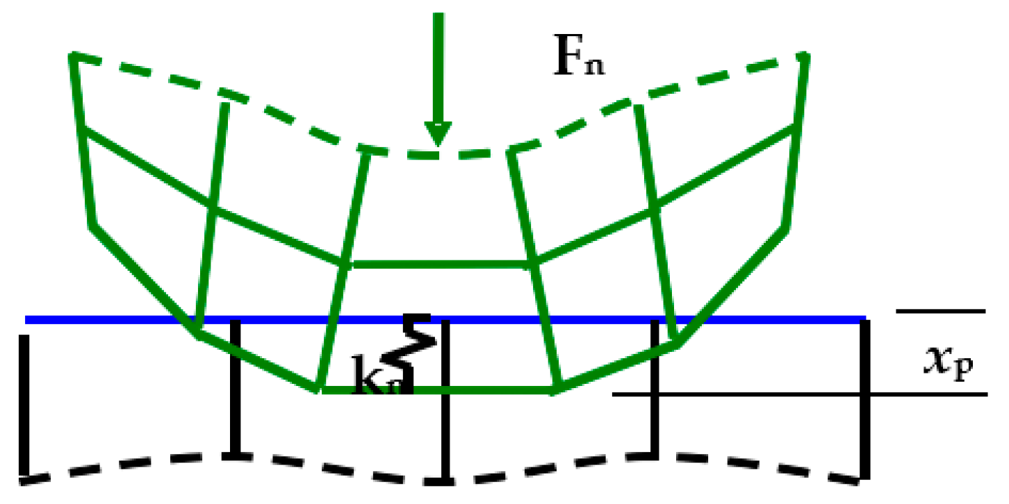
In this analysis, we selected the augmented Lagrange algorithm to find the solution of the contact problem (surface-to-surface contact). The algorithm is based on the iterative penalty method and, through the equilibrium iterations, the frictional stresses and pressure are increased. Therefore, the value of the penetration (final value) is less than the permissible tolerance. This algorithm can be considered as optimal for its lower sensitivity to constant stiffness. The contact force/pressure relationship between two contact bodies can be written as follows (
Figure 4):
where
λ is the Lagrange multiplier component.
Based on the real dimensions, an accurate three-dimensional model of the main parts of the dry clutch system (pressure plate, clutch disc and flywheel) was developed using SOLIDWORKS 2020. After checking the model and the surfaces of contact, the model was exported to ANSYS/Workbench 2020.
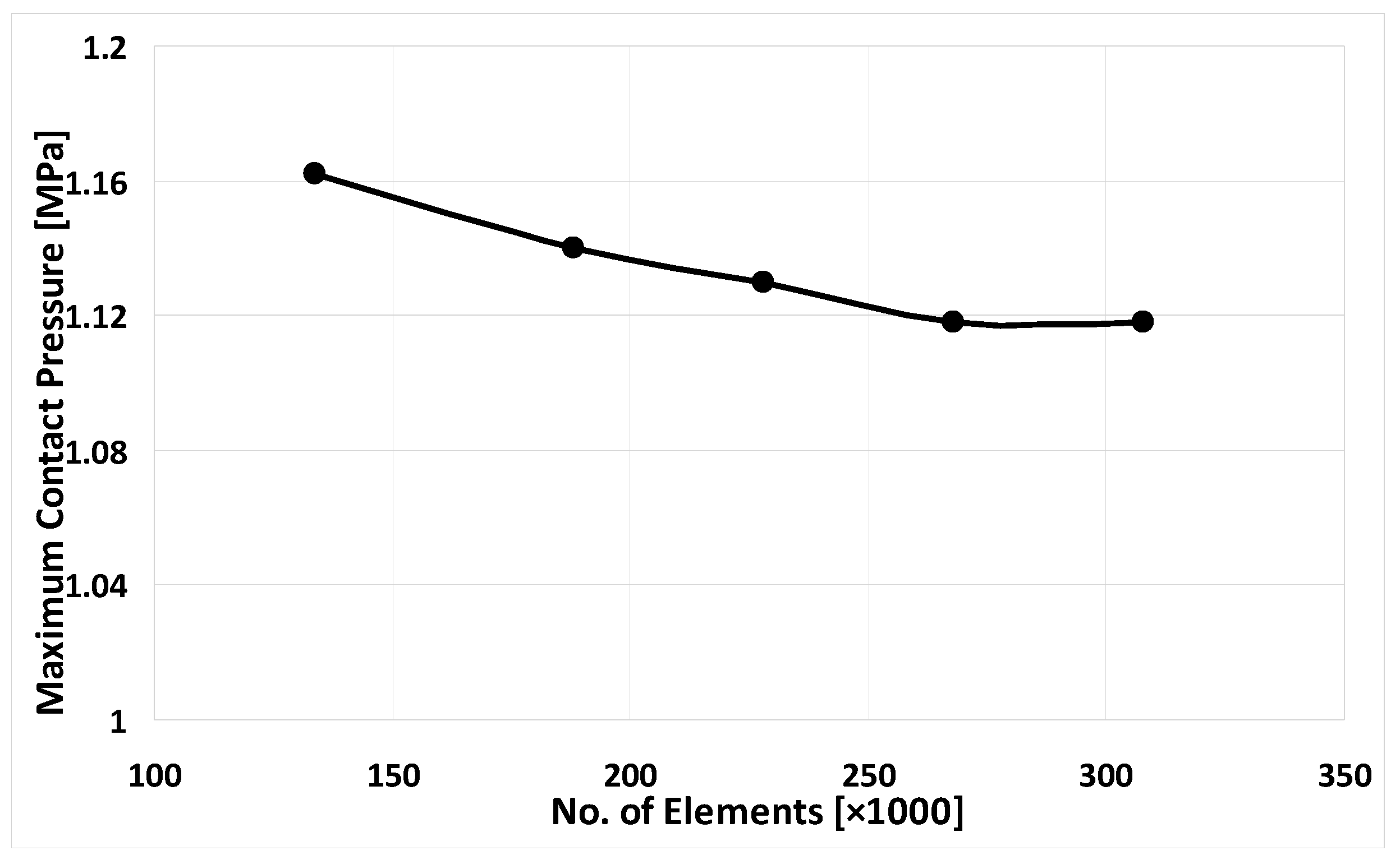
Figure 5 shows the optimal finite element model of the friction clutch system. This mesh type was selected after performing the mesh dependency test. The full Newton–Raphson with unsymmetrical matrices of elements was chosen to achieve the numerical solution including the large deflection. For all numerical analyses, the materials are assumed isotropic and homogeneous.
Table 1 shows the main characteristics of the materials, dimensions and the operational parameters. The selected type of the frictional material was sintered metal (dry), where the range of maximum pressure was (2–2.75 MPa), the maximum allowable temperature for continuous and instantaneous cases are 622 K and 822 K, and the maximum allowable velocity was 1097.28 m/s [
16].
Figure 5 shows the mesh independence test to select the optimal finite element model of the clutch system. The selected FE model had 1,164,367 nodes (268,675 elements).
Figure 6 shows the flowchart finite simulation of the solution of the contact problem of clutch system.
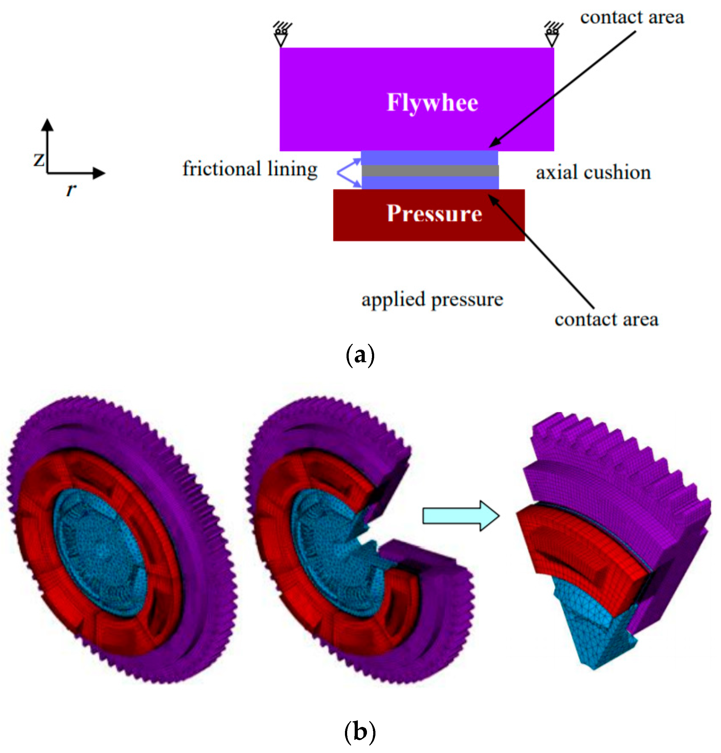
Figure 7 demonstrations the disassembly of the contacting elements of the clutch system (sector). The types of the element used to build the contact finite element mode of the clutch system can be seen.
The main development achieved in this work is to create a new accurate three-dimensional model of the dry clutch system from scratch taking into consideration all complexities of the geometry to find the numerical solution of the contact problem during the full engagement. The vast majority of researchers use the 2D axisymmetric model to find the solution [
2,
3,
4,
5,
6]. The most important features of the new 3D model is the capability to find the solution for more complex problems that occur in the dry clutch system such as wear, effect of roughness, effect of defects, etc.
Figure 5 shows the flowchart finite simulation of contact problem solution for clutch system
Figure 6 shows the disassembly of the contacting elements of the clutch system (sector). The types of the element used to build the contact finite element mode of the clutch system can be seen.
3. Results and Discussions
Generally, in most machine elements, increasing in the magnitude of stiffness is considered a desirable feature. However, in some cases such as in dry friction clutches, the magnitude of the structural stiffness should be carefully limited (e.g., trade-off structural stiffness in some cases). This is very important to ensure the frictional clutch works within the safe zone (safe temperature). The structural stiffness is propositional directly with the materials properties (Young’s modules E) of the contacting elements. Based on this fact, this new analysis was achieved to present the effect of values of modulus of elasticity on the contact pressure distribution of the dry friction clutch.
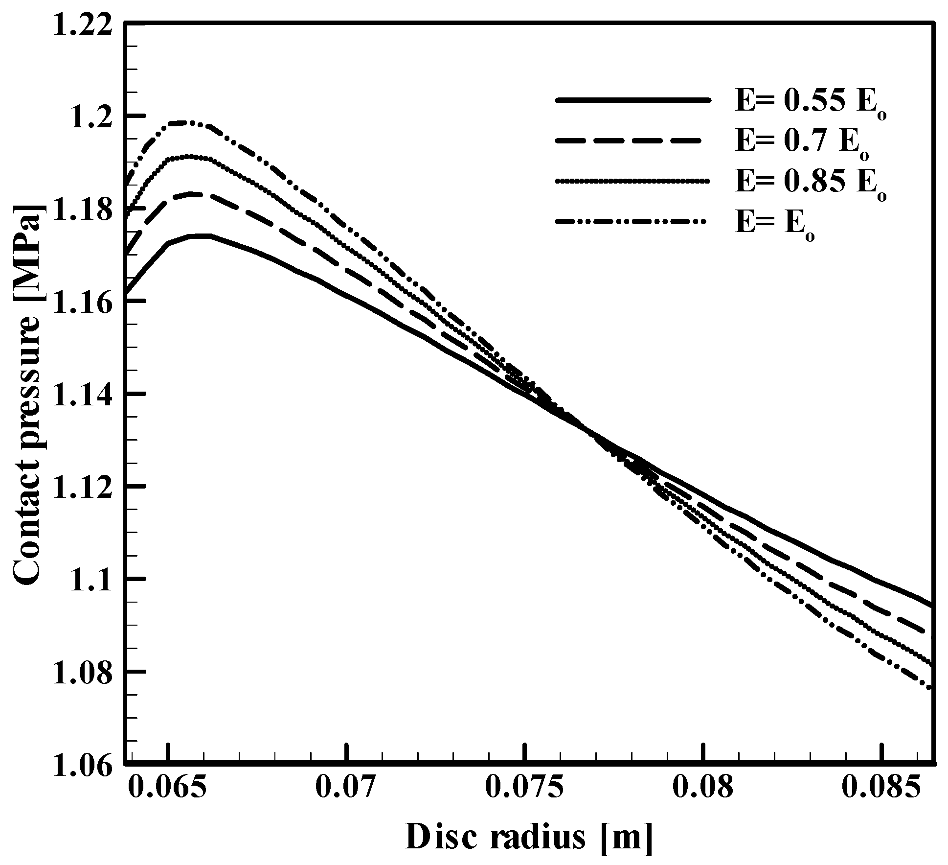
Figure 8 shows the contact pressure distribution along the disc radius between the clutch disc and the pressure plate by using different values of modules of elasticity of frictional materials under the same working conditions. It can be noticed for all the cases that the maximum value occurred near the inner radius (at
r = 0.065 m). Behind this point, the values of the contact pressure decreased until reaching the minimum value at the outer radius. The main reason for this distribution of the contact pressure is the restriction conditions and the geometry of the contacting parts of the clutch system. The highest values of contact pressure (1.198 MPa) occurred when the value of modulus of elasticity is highest (
).The minimum value of the contact pressure (1.173 MPa) occurred when using the lowest value of modulus of elasticity (
). However, all values of the contact pressures for all cases were equal at
r = 0.077 m, and the values of contact pressure was (1.13 MPa).
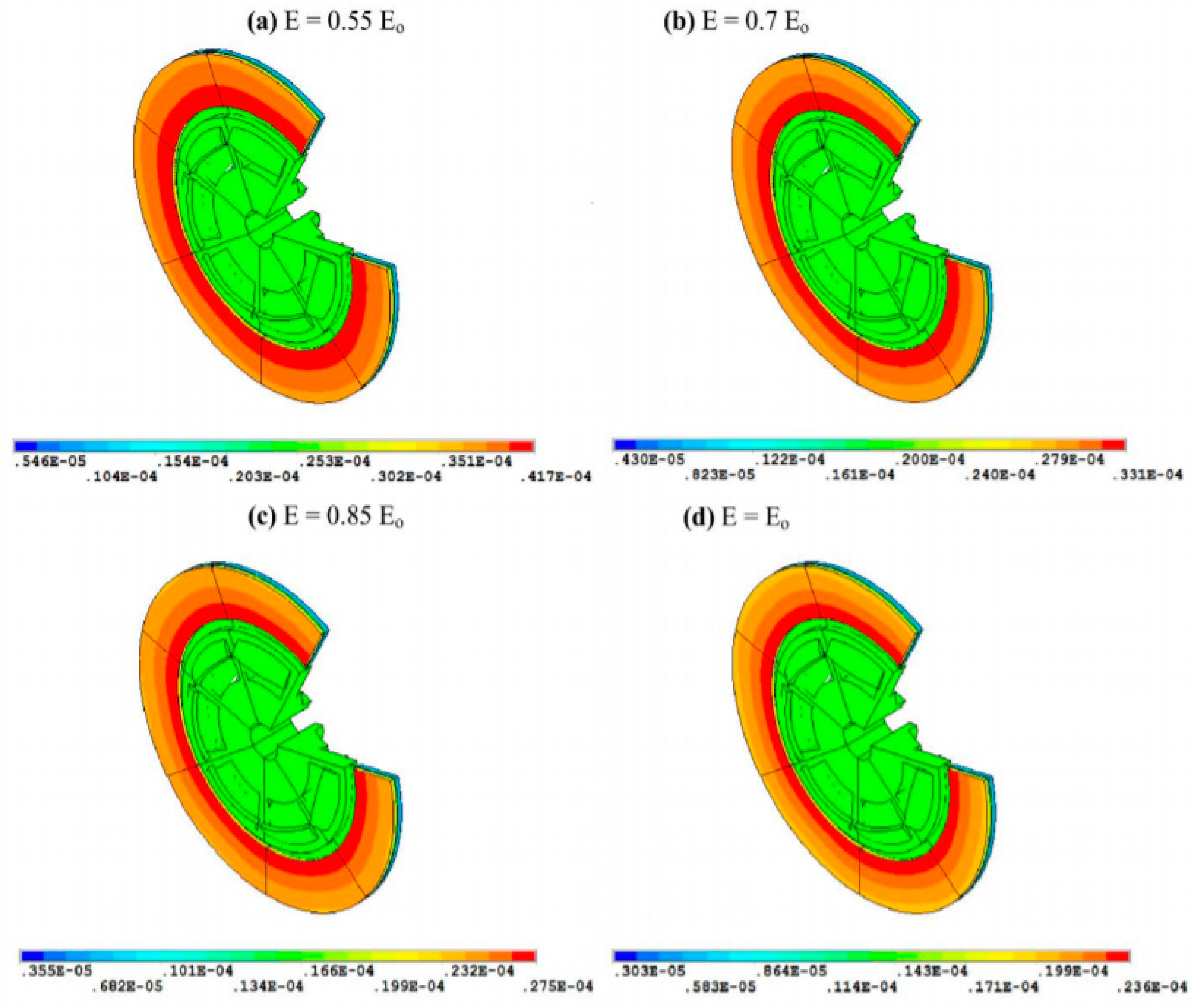
Figure 9 illustrates the contours of the contact pressure distribution between the friction clutch disc and the pressure plate when using different values of modulus of elasticity for the frictional material (
1234). It is obvious that the minimum values of contact pressure (peaks) occurred when using the minimum value of in the set of modulus of elasticity (
).The maximum value of contact pressure occurred using the maximum value of modules of elasticity (
). The results denote that any reduction in the magnitude of the modulus of elasticity causes the reduction the structural stiffness of the frictional facing. This leads to a reduction in the values of the contact pressure and homogenizes the contact distribution. Based on this methodology to control the structural stiffness of the contacting elements (properties of material), undesirable phenomena such as hot spots can be avoided [
17]. Generally, the highest values of contact pressure occurred near the inner disc radius. The reason behind the results of contact pressure distribution is the geometry of the contacting elements (pressure plate, clutch disc and flywheel). Where the external pressure is applied on the backside of the pressure plate, this will cause the compression between the clutch’s elements.
Figure 10 demonstrates the contours of the deformation for the same four cases. It can be observed that the maximum deformation occurred when using the frictional facing with the lowest value of modulus of elasticity (
). On the other hand, the minimum values of deformation appeared when using the frictional facing that has the highest value of modulus of elasticity (
). In general, the distributions of deformations are semi-uniform over the contacting area for all cases, because of there is a small gradient in the contact pressure without thermal influence. On the other hand, in the case of hot spots, the distributions of displacements will be not uniform any more.
4. Conclusions and Remarks
In many mechanical applications, the stiffness and the strength are considered crucial design criteria. With reference to dry clutch systems, this research focuses on fundamental steps to achieve numerical analysis with highly accurate results for contact, thermal, thermo-elastic, and wear distributions. A three-dimensional model was built, after overcoming the complexities of the geometry of the friction clutch system, by overcoming the limits found in previous research whose core was a two-dimensional model (axisymmetric). The novelty of this work is the creation of the valid 3D model with capability to obtain very accurate results for contact and thermal problems. This will open the door to go further to find new solutions for very complex cases that relate to wear, hotspot, flash temperature, surface roughness, etc. Indeed, in this research, the effect of the modules of elasticity (structural stiffness) of the frictional facing on the contact pressure distribution and the deformations between the elements of the dry friction clutches (pressure plate, clutch disc and flywheel) was investigated.
As a main finding, it was found that the contact pressure decreased with a reduction of the structural stiffness (modules of the elasticity) of the frictional facing, whereas the displacements were increased. Based on the outcomes obtained, the structural stiffness of the friction facing has been found as variable with a marked effect on the contact distribution of contact elements. This effect is more evident during the sliding period due to the frictional heat generation. The reduction of the structural stiffness of the frictional facing leads to an increase in the tendency of the frictional system to operate in the stability zone.

 ,
, 


