Article

Study of the Kinematics and Dynamics of the Ring Pack of a Diesel Engine by Means of the Construction of CFD Model in Conjunction with Mathematical Models

by
Wilman Orozco Lozano
1,*,
Marlen Del Socorro Fonseca-Vigoya
2 and
Jhon Pabón-León
2
1
Programa de Ingeniería Mecánica, Universidad Antonio Nariño, Km 7, Antigua Via a Puerto Colombia, Puerto Colombia, Bogotá 080001, Colombia
2
Programa de Administración de Empresas, Universidad Francisco de Paula Santander, Avenida Gran Colombia No. 12E-96 Barrio Colsag, San José de Cúcuta 540001, Colombia
*
Author to whom correspondence should be addressed.
Lubricants 2021, 9(12), 116; https://doi.org/10.3390/lubricants9120116
Submission received: 25 October 2021 / Revised: 24 November 2021 / Accepted: 26 November 2021 / Published: 28 November 2021
(This article belongs to the Special Issue Advances in Tribology and LCA Applied to Thermal Machines)

Abstract

:
The present research aims to analyze the kinematic and dynamic behavior of the piston ring package. The development of the research was carried out through the development of numerical simulation by means of CFD. The analysis involves the three piston rings for the development of simulations that are closer to the real conditions of the engine since most of the investigations tend to focus on the study of the compression ring only. The simulation was reinforced by the incorporation of mathematical models, which allow determining the piston kinematics, the lubrication properties as a function of temperature, contact friction, and gas leakage. For the simulation, the CAD of the piston and the connecting rod—crankshaft mechanism was carried out, taking as a reference the geometry of a diesel engine. From the results obtained, it was possible to show that the first ring exhibits considerably greater radial and axial movement compared to the second and third piston rings. Additionally, it was shown that the first and second rings tend to maintain a negative tilt angle throughout the combustion cycle, which facilitates the advancement of the combustion gases over the piston grooves. Therefore, it is necessary to use strategies so that these rings tend to maintain a positive inclination. The analysis of the pressure conditions in the second ring are 150% and 480% higher compared to the conditions present in the third ring. Due to the above, it is necessary to focus efforts on the design of the profile of this ring. The study of energy losses showed that the combination of leakage gases and friction are responsible for a mechanical loss between 6–16%. In general, the development of the proposed methodology is a novel tool for the joint analysis of the kinematic characteristics, pressure conditions, and energy losses. In this way, integrated analysis of changes caused by piston ring designs is possible.

1. Introduction

Currently, internal combustion engines (ICEs) play an indispensable role as propulsion systems in the transport sector. Despite the advancement of new technologies, ICEs are expected to remain relevant in the coming decades [1,2,3]. One of the main problems of ICEs is the low use of fuel energy. In general, only 21% of the fuel energy is used for the useful mechanical power of the engine [4]. The remaining percentage is loss by heat transfer processes, auxiliary engine systems, and mechanical losses. Due to this situation, researchers have dedicated themselves to finding alternatives to improve fuel efficiency and minimize the environmental impact of ICEs.
The piston rings are intended to provide a tight seal between the cylinder liner and the piston. Additionally, the rings contribute to the distribution and control of the lubricating oil. Despite their benefits, piston rings in ICEs are one of the main sources of energy losses due to the friction processes that occur in these elements. Therefore, the study of tribological performance is of utmost importance to improve fuel economy. Losses associated with friction processes have a significant impact on fuel consumption and harmful emissions for the environment, as is the case of CO2 [5,6]. The friction losses present in the piston assembly can represent approximately 50% of the total friction losses in ICEs [7]. Much of this percentage of losses is located in the piston ring package [8]. Therefore, it is necessary to achieve a better compression of the complex processes related to the interaction between the piston rings and the cylinder liner, which influence friction, wear, sealing capacity, consumption of lubricating oil, among other factors. This is of utmost importance to achieve an increase in performance and a reduction in fuel consumption [9]. Another problem present in piston rings is leakage loss in the combustion chamber. Studies estimate that the leakage losses are equivalent to a loss of 0.5% of the total energy input of the fuel [10]. On the other hand, Turnbull et al. [11] noted that leakage losses are six times higher compared to energy losses associated with friction processes. Despite the importance of this type of energy loss, there are few quantitative analyzes available in the literature that evaluate the impact of leaks on engine performance. Bolander et al. [12] experimentally and theoretically investigated the lubrication conditions and losses associated with friction between the piston ring and the cylinder liner. Avan et al. [13] studied through the development of experimental tests the thickness of the lubrication film. Zavos et al. [14] investigated by means of numerical simulation and experimental tests the deformations of the ring in a single-cylinder engine as a consequence of the friction between the compression ring and the cylinder liner.
Starting in the 20th century, numerical models and mathematical models have become a powerful tool used by many researchers to describe the complex processes present in the ICE piston assembly. Koszalka [15] investigated by means of numerical simulations the impact of ring and piston geometry on the performance of diesel engines. Oliva and Held [16] performed a numerical investigation for the analysis of the lubrication oil distribution and leakage in the piston ring package. Skoblo et al. [17] studied the mechanism of piston ring wear in a diesel generator by simulating real operating conditions. Niralgikar and Bulsara [18] analyzed compression ring wear in an internal combustion engine by studying the profile of the piston ring. Delprete et al. [19] evaluated the tribological phenomena of the piston skirt under poor lubrication conditions. From the developed numerical method, the secondary movement and the hydrodynamic pressure in the piston were studied. Delprete et al. [20] analyzed the sealing capacity of the combustion chamber and its effect on emissions. The results show that the ring pack and piston skirt are responsible for the majority of mechanical losses in internal combustion engines. Delprete et al. [21] developed a model to estimate the minimum thickness of the lubricating oil film and the power loss of the piston rings under hydrodynamic lubrication conditions. The model considers the geometry of the profile and the mechanical properties of the ring. Baker et al. [22] demonstrated the dynamics of the rings play a relevant role in lubrication oil consumption, friction processes, unburned hydrocarbon products, and oil degradation. This has an impact on the amount of gas leaks in the combustion chamber [23,24].
Despite the research available in the literature focused on the engine piston, most of it concentrates on the analysis of the compression ring without considering the behavior of the other rings. Due to the above, in the present investigation, a study of the piston ring package is carried out through the use of CFD numerical simulation and mathematical models. The research carried out involves the kinematic analysis of the three piston rings, the pressure conditions in the lands, and the ring grooves. As well as the evaluation of the energy lost as a consequence of friction and leaking gases. The above, with the aim of implementing a methodology that allows to comprehensively evaluate the influence that the three piston rings have on operating conditions and energy losses in internal combustion engines.

2. Test Bench Engine

The analysis of the set of piston rings in the present investigation is based on the physical and operational characteristics of a direct injection four-stroke diesel engine with a maximum power of 95 kW with reference Isuzu 4JJ1. Table 1 indicates the main technical specifications of the test engine.
The geometric characteristics of the piston rings are shown in Figure 1. The first ring corresponds to the trapezoidal-shaped compression ring. The second and third piston rings are responsible for the control and distribution of the lubricating oil, whose shape corresponds to a Napier ring and a beveled edge ring.
The profile of the first ring corresponds to a conical geometry, which allows improving the hydrodynamic lubrication conditions, as a consequence of the lubrication oil that tends to lodge in the upper and lower face of the ring. Additionally, the contact surface is considerably reduced, which improves the sealing characteristics. The profile of the second ring has a right-angle trapezoidal geometric shape, with a chamfer shape on its lower surface. This avoids the accumulation of oil between the ring and the cylinder liner, achieving a better distribution of the lubrication oil. Additionally, the chamfer shape allows a reduction in the weight of the ring. In the case of the third ring, this is characterized by the presence of two beveled edges that protrude from the profile of the ring in order to increase the contact pressure between the ring and the sleeve. In this way, greater control of the lubrication and tightness of the combustion chamber is guaranteed.
The lubricating oil taken as reference is SAE 10W40 lubricant. The physicochemical properties of the lubricant are shown in Table 2.

3. Auxiliary Mathematical Models

To improve the details of the numerical analysis, the use of auxiliary mathematical models is proposed, which are subsequently integrated into the CFD model. The models implemented in the research are detailed below.

3.1. Piston Kinematics

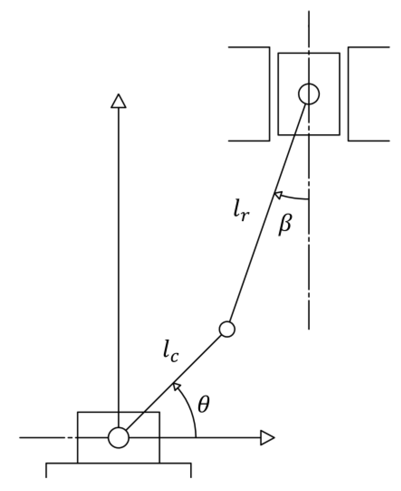
To describe the kinematic behavior of the piston mechanism (connecting rod, crankshaft, and piston), the system is considered as a sliding crank mechanism [25]. The piston mechanism is described in Figure 2.
To determine the velocity and acceleration of the piston, the equation matrices described below were solved using complex algebra.
[ l c · ω c · sin θ l c · ω c · cos θ ] = [ l r · sin β 1 l r · cos β 0 ] [ ω r e l v p ]
[ l r · sin β 1 l r · cos β 0 ] [ α r e l a p ] = [ l c · ω c 2 · cos θ l r · ω r e l 2 · cos β l c · ω c 2 · sin θ + l r · ω r e l 2 · sin β ]
where l c is the length of the crankshaft, l r is the length of the connecting rod, v p is the piston velocity, a p is the piston acceleration and ω c is the angular velocity of the crankshaft. ω r e l and α r e l are the relative angular velocity and acceleration of the movement between connecting rod and piston. β is the angle between the connecting rod and the piston displacement axis, which is determined by Equation (3).
β = sin 1 ( l c · sin θ + d l r )
where d is the horizontal distance between piston axis (see Figure 2).

3.2. Lubrication Oil Properties

The properties of the SAE 10W40 lubricating oil are introduced into the CFD model by means of functions that depend on the temperature and pressure conditions. To determine the density of the lubricating oil ( ρ ) , the relationship proposed by Dowson and Higginson [26] was used, as shown in Equation (4).
ρ = ρ o ( 1 c t h [ T T o ] ) · ( 1 + 6 × 10 10 · [ p p o ] 1 + 1.7 × 10 9 · [ p p o ] )
where ρ o and p o are the density and pressure of the lubricating oil at ambient conditions. c t h is the coefficient of thermal expansion. In the case of the dynamic viscosity of the lubricating oil ( μ ) , the model proposed by Houpert [27] was used, as shown in Equation (5). In the literature, there are different numerical models for the analysis of lubrication properties. However, some have limitations in their range of application, as is the case with the model proposed by Barus, which is inaccurate under high-pressure conditions [28]. The expression proposed by Houpert is one of the models with greater precision. Due to the above, it is one of the main models used in numerical simulation studies [28].
μ = μ o · e ( 1 + p p o c p ) Z ln ( μ o μ ) ( T 138 T o 138 ) S o   ln ( μ o μ )
where μ o is the dynamic viscosity of the lubricating oil at ambient conditions, Z is the lubricant piezo-viscosity index, S o is the thermo-viscosity index. c p and μ are model constants, defined as 1.98 × 10 8   Pa · s and 6.31 × 10 5   Pa · s , respectively. Z and S o are calculated using Equations (6) and (7).
Z = α o · c p ln ( μ o μ )
S o = β o · ( T o 138 ) ln ( μ o μ )
where α o is the atmospheric piezo-viscosity coefficient and β o is the thermo-viscosity coefficient, respectively.

3.3. Contact Friction Model

A contact friction force occurs on the surface of the piston rings, which is the consequence of two factors. The first is due to the interaction with the surface asperities that protrude from the lubrication film. The second factor is the result of shear caused by the viscosity of the lubricating oil. Therefore, the contact friction force ( f c ) is determined by Equation (8).
f c = f v + f a
where f v is the viscous friction force and f a is the asperity friction force. The calculation of f v is carried out using Equation (9).
f v = τ · ( A A e )
where τ is the viscous shear stress of the lubricating oil, A is the apparent contact area and A e real contact area between ring and liner, respectively. τ is calculated by means of Equation (10) [29].
τ = | p h 2 + v p μ h |
where h is the lubricant film thickness. The calculation of f a is determined by means of Equation (11).
f a = ζ · W l + τ o · A e
where ζ is the coefficient of asperity shear strength ( ζ = 0.17 ) [30], τ o is the limiting Eyring shear stress of the lubricating oil and W l is the asperity contact load, respectively. The real contact area between ring and liner ( A e ) is defined by Equation (12).
A e = A · F 2 ( λ ) · π 2 · ξ 2 · κ 2 · σ 2
where κ is the average radius of curvature of asperities, ξ is the density of asperity peaks per unit area, and σ is the surface roughness. F 2 ( λ ) is an approximate statistical function using a fifth-order polynomial, as indicated in Equation (13) [31].
F 2 ( λ ) = { 0.0018 λ 5 + 0.0281 λ 4 0.1728 λ 3 + 0.5258 λ 2 0.8043 λ + 0.5003 ,       λ 2.295 0 ,         λ > 2.295 }
where λ is the Stribeck’s lubricant film ratio. The asperity contact load ( W l   ) is determined by Equation (14).
W l = 16 2 15 · A · π · F 5 / 2 ( λ ) · E · ξ 2 · κ 3 2 · σ 5 2
where F 5 / 2 ( λ ) is a statistical function of lubricant film ratio using a fifth-order polynomial, as indicated in Equation (15).
F 5 / 2 ( λ ) = { 0.0046 λ 5 + 0.0574 λ 4 0.2958 λ 3 + 0.7844 λ 2 1.0776 λ + 0.6167 ,       λ 2.224 0 ,         λ > 2.224 }

3.4. Blow-By Model

The mass flow between the piston surface and the groove of each piston ring is determined by considering the calculation as an isentropic flow through an orifice, as shown in Equation (16) [32].
m ˙ b = f m · c d · A r · P u R 1 2 · T u 1 2
where c d is the coefficient of discharge, T u is the upstream orifice temperature, A r is the ring end-gap area and R is the gas constant, respectively. f m is the compressibility factor, which is determined by Equation (17) [32].
f m = { r s · ( 2 r s + 1 ) r s + 1 2 ( r s 1 )     ,       P d P u > ( 2 r s + 1 ) r s ( r s 1 ) 0.85 0.25 ( P d P u ) 2     ,       P d P u ( 2 r s + 1 ) r s ( r s 1 ) }
where P u is the upstream pressure, P d is the downstream pressure and r s is the ratio of specific heats. The power loss associated with the gas blow-by is calculated from Equation (18) [33].
P b = m ˙ b · r s · R · T u r s 1 · ( 1 ( P d P u ) r s 1 r s )
The blow-by model requires as an input parameter the pressure conditions at the top ( P u ) and bottom ( P d ) of each ring. The above corresponds to the pressure levels in the first, second, and third piston land. As well as, the pressure conditions in the engine crankcase. Table 3 describes the pressure values throughout the combustion cycle for a torque condition of 408 Nm and a rotation speed of 2000 rpm.

3.5. Tribological Model

To determine the lubrication film, the one-dimensional Reynolds equation was used, as indicated in Equation (19), [34].
x ( h 3 p x ) = 6 μ v p h x + 12 μ h t
where h is the thickness of the lubrication film and p is the pressure between the ring surface and the cylinder liner. To determine the pressure ( p ) Equation (20) was used.
p = 6 μ v p 1 h 2 d x + 12 μ d h d t x h 3 d x + c 1 1 h 3 d x + c 2
where c 1 and c 2 are constants of integration. These constants are determined by the limit conditions of hydrodynamic pressure in the profile of the piston ring, which depend on the cavitation produced in the lubrication film [35].

4. CFD Procedure

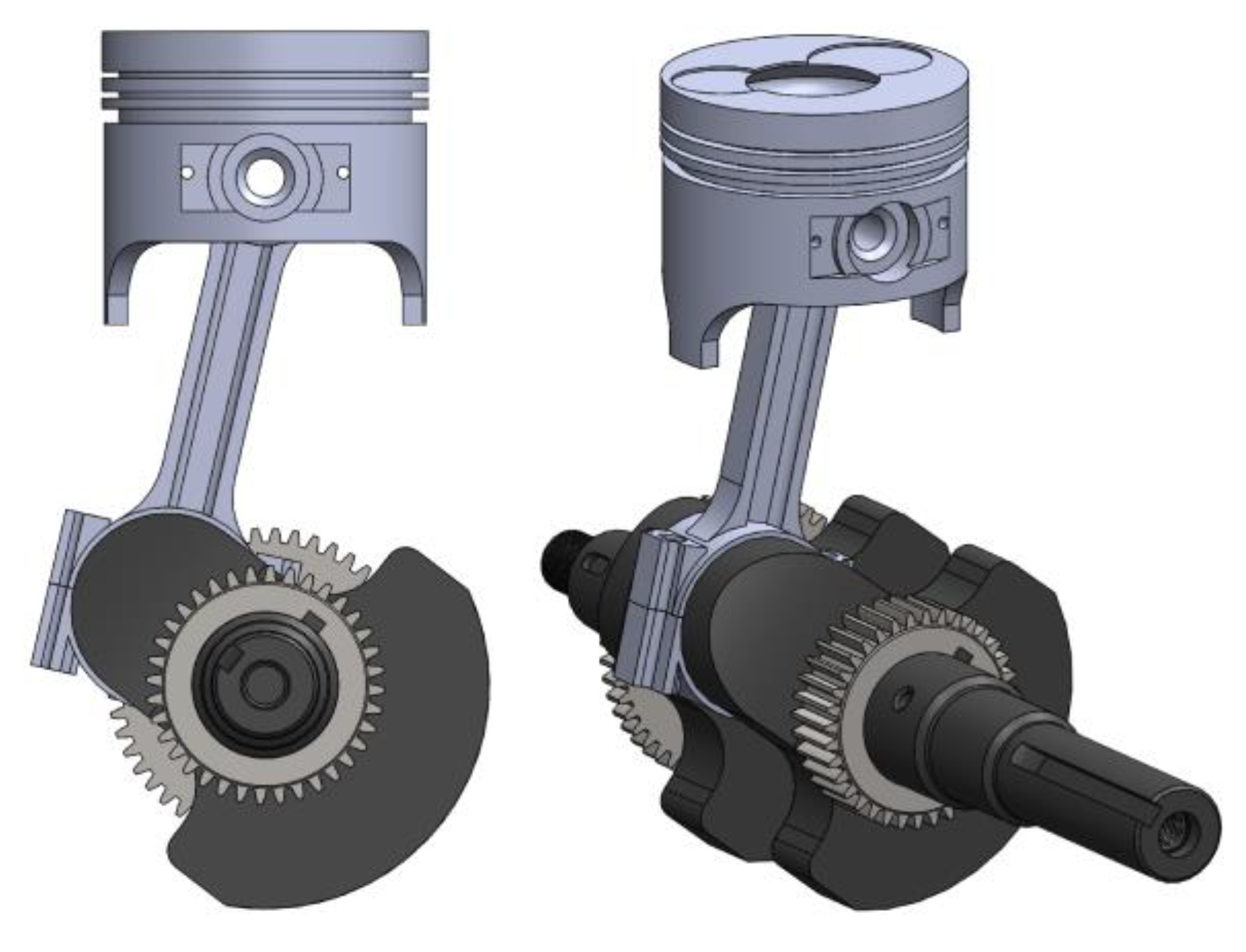
For the CFD modeling, the geometric CAD of a piston was built, which is based on a diesel engine, whose characteristics are indicated in Table 1. The details of the piston geometry are shown in Figure 3.
The computational domain is limited by the surface of the piston and the outer walls of the rings. Additionally, the volume of the combustion chamber and the connecting rod-crankshaft mechanism are considered to describe the movement of the piston throughout the combustion cycle. Velocity and acceleration are defined by the algebraic matrix indicated in Equations (1) and (2). The CFD simulation is carried out by means of the free software OpenFOAM. The mesh development was carried out using the SALOME software, in which a hexahedral mesh was generated. The behavior of the fluid and the pressure inside the combustion chamber is governed by the Navier–Stokes equations. The temperature conditions inside the cylinder chamber are based on the temperature curves throughout the combustion cycle obtained through experimental tests. The convergence of the simulations is established when the residuals reach values of 10 4 for the kinetic energy of turbulence, 10 4 for the dissipation rate and 10 7 for the energy [36].
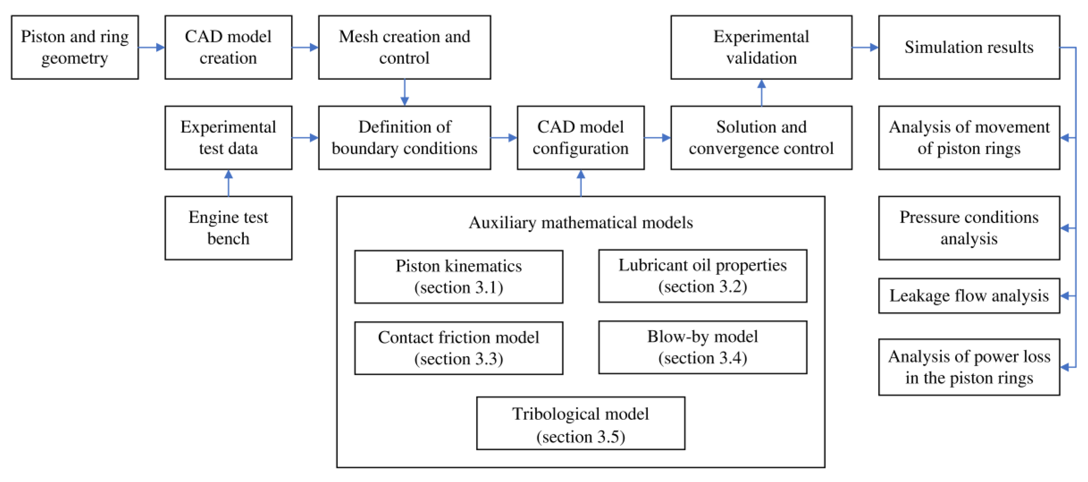
The boundary conditions were established based on the operating characteristics of the engine with a torque of 408 Nm and a rotational speed of 2000 rpm. The properties of the lubricating oil were considered as a function of pressure and temperature, as indicated in Equations (4) and (5). The initial lubrication oil distribution was established at a thickness of 5 μ m . The foregoing refers to the initial coating of the lubricating oil film on the cylinder liner. In the case of the areas between the cylinder liner and the profile of the rings, a distribution of 10% lubricating oil and 90% air was established. The methodology for the development of the CFD model is shown in Figure 4.
From the experimental tests in a test bench, the boundary conditions are defined, which correspond to the pressure levels in the combustion chamber, temperature, and mass flow throughout the combustion cycle. Additionally, the geometric data of the piston, rings, and cylinder liner are taken as a reference. The configuration of the CFD model is complemented with the auxiliary mathematical models described in Section 3. From the simulation results, the analysis of the movement of the piston rings, pressure conditions, analysis of leakage flow, and loss of power. Discussions of these analyzes are noted in Section 5.
To verify the reliability of the simulation results, an experimental validation was carried out, taking as a reference the pressure conditions in the piston second and third lands (see Figure 10). For this, pressure transducers were installed in the piston body. The results of the comparison between the simulations and the experimental data are shown in Figure 5.
From the results obtained in Figure 5, it was possible to show that the curves obtained through the numerical simulation describe a highly similar trend compared to the experimental data. In the case of the second land, an average error of 9% was obtained throughout the combustion cycle. For the third land, the average error obtained was 8%, respectively. However, areas of greater deflection occur during the compression and expansion stages. This can be the consequence of factors such as sudden variations in combustion chamber pressure and changes in lubrication properties. Despite the above, the maximum error in the pressure of both lands remained less than 15%, which allows demonstrating that the estimates of the numerical simulation are congruent with the real behavior of the engine.

5. Results and Discussion

5.1. Analysis of Movement of Piston Rings

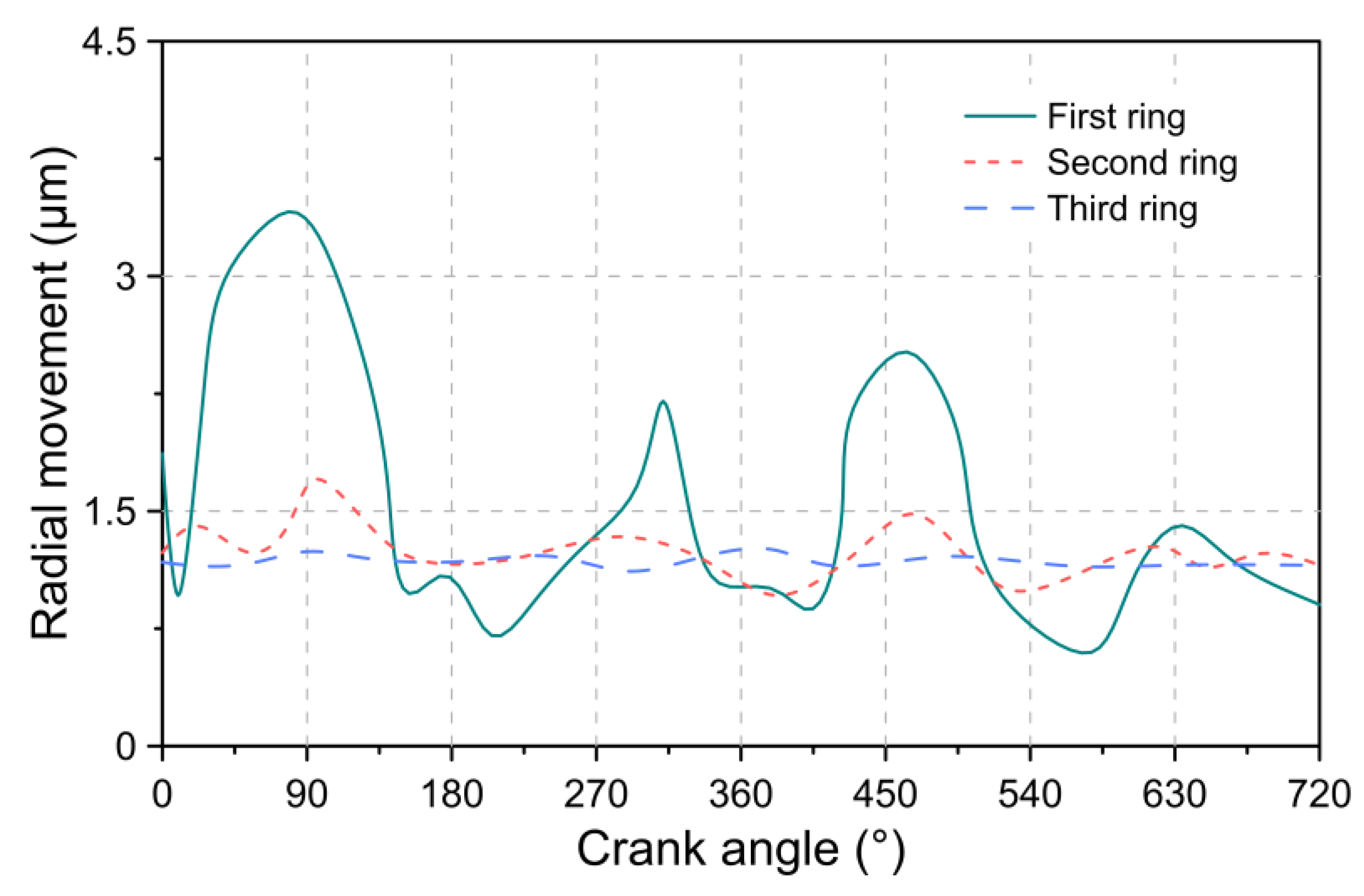
Figure 6 describes the radial movement experienced by the piston rings throughout the combustion cycle.
From the results obtained in Figure 6, it was observed that the compression ring (first ring) is the one that experiences a greater degree of radial movement compared to the second and third rings, respectively. For the simulated condition, a maximum displacement of 3.4, 1.7, and 1.3 μ m were obtained in the first, second, and third rings. The greater displacement of the first ring can be a consequence of the high pressure, which acts on the rear part and the front face of the ring. Additionally, the high-pressure conditions inside the combustion chamber cause an increase in the friction force caused by the viscosity of the lubricating oil since the viscous shear stress is directly associated with the pressure gradient, as indicated in Equation (10). The above tends to favor the imbalance of the rings.
The pressure levels in the ring grooves decrease as the gas flow decreases, which explains the damping of radial movement. Additionally, it was evidenced that the greatest radial movement occurs approximately during an angle of 90°, 315°, 450°, and 630°, which corresponds to a condition of ascent and descent of the piston. This implies that the contact force due to the friction produced between the cylinder liner and the face of the piston rings has a significant influence on the radial movement of the piston rings.
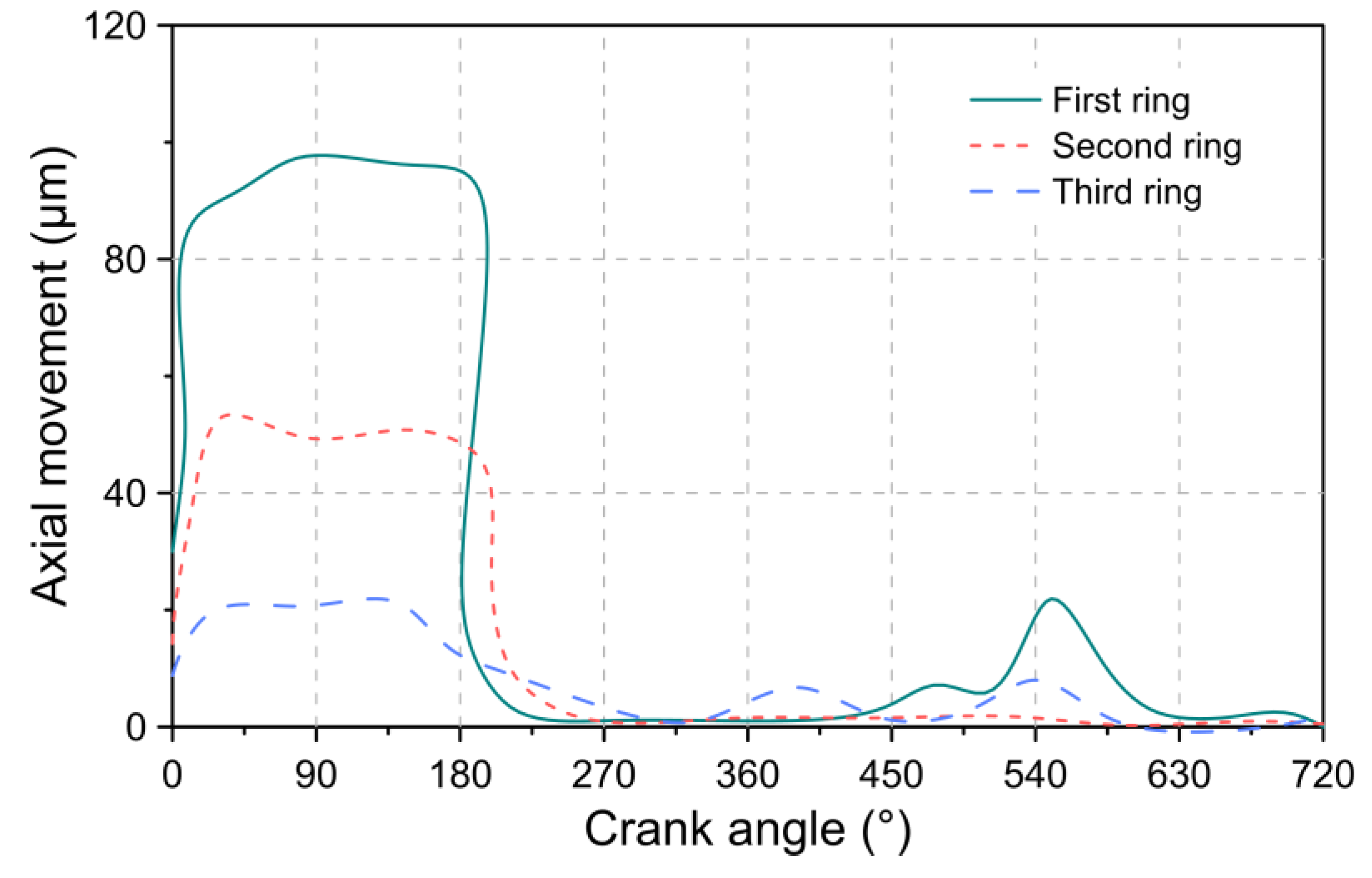
Figure 7 shows the axial movement of the piston rings, in which position 0 indicates that the ring is located at the bottom of the piston groove.
The highest axial movement was obtained for a crankshaft angle between 0–180°, corresponding to the intake stage. During this stage, the piston is in a downward stroke, therefore the main force acting on the rings is the inertial force. Additionally, during intake, the frictional force of the lubricating oil greatly exceeds the force caused by pressure in the ring grooves, which tends to keep the rings seated on top of the grooves. However, during the compression stage (between 180–360°) and expansion (between 360–540°), the movement is reversed as a result of the high pressures on the upper surface of the rings. The second lift of the piston rings was obtained during the final expansion stage. This behavior is the result of an increase in pressure on the lower face, which tends to raise the rings. The maximum axial displacement for the simulated conditions was 97.1, 53.2, and 21.1 μ m for the first, second, and third piston rings, respectively.
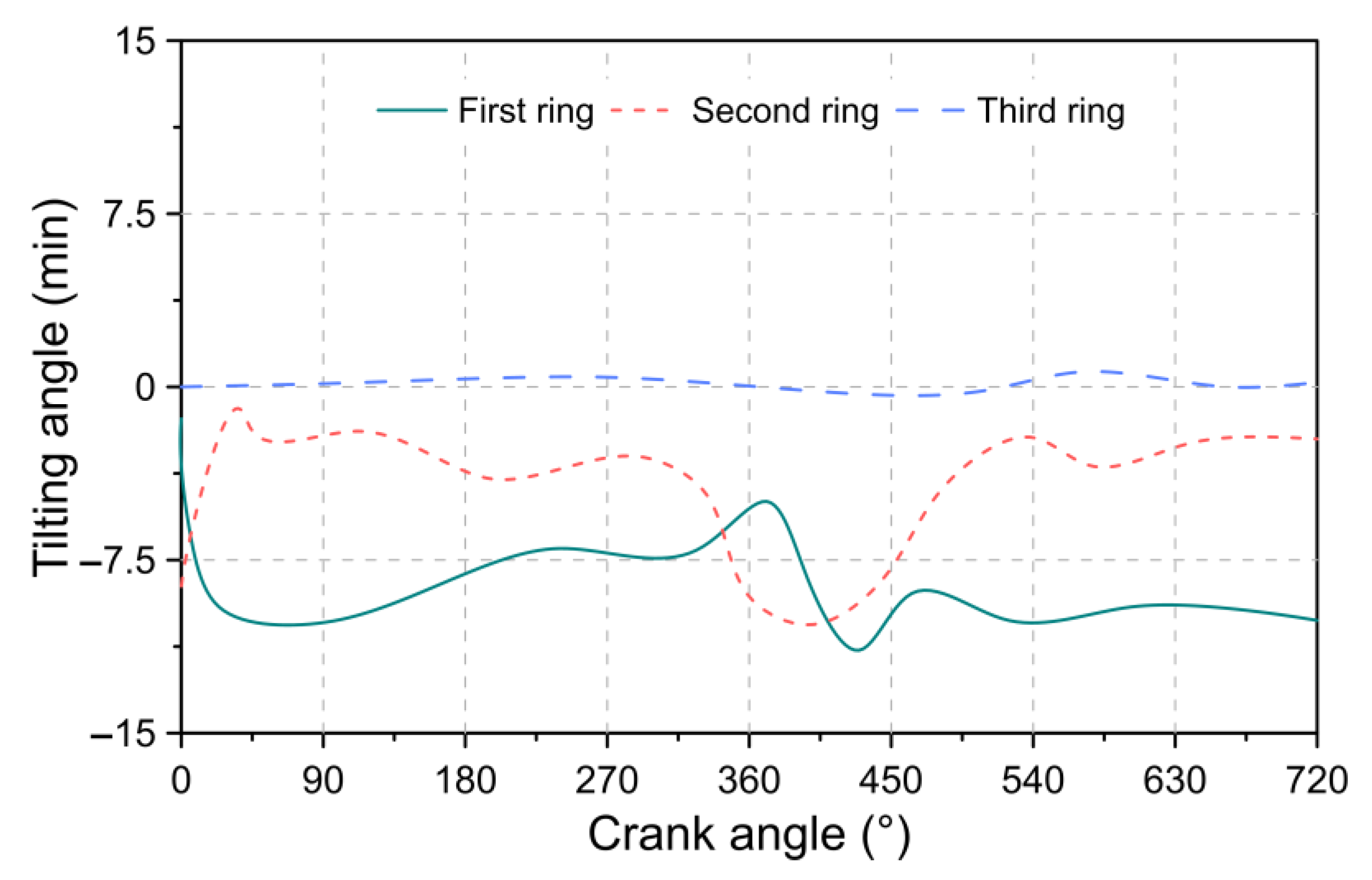
The angle of inclination for the three piston rings is depicted in Figure 8. The positive angle indicates that the ring tends to set towards the outside diameter (see Figure 9a) and towards the inside diameter for a negative angle of inclination (see Figure 9b).
In the case of the first ring, it was observed that it tends to maintain a negative angle of inclination throughout the combustion cycle. Due to this position, part of the gases can advance through the upper groove of the first ring, which produces a lifting thrust from the lower surface of the ring. This implies a lower sealing capacity of the chamber since the ring is not capable of sealing the path of the gas flow. The above condition significantly affects the second piston ring since it also has the same negative inclination as the first ring, which is a consequence of the pressure exerted by the leakage of gases on the upper face of the ring.

5.2. Pressure Conditions Analysis

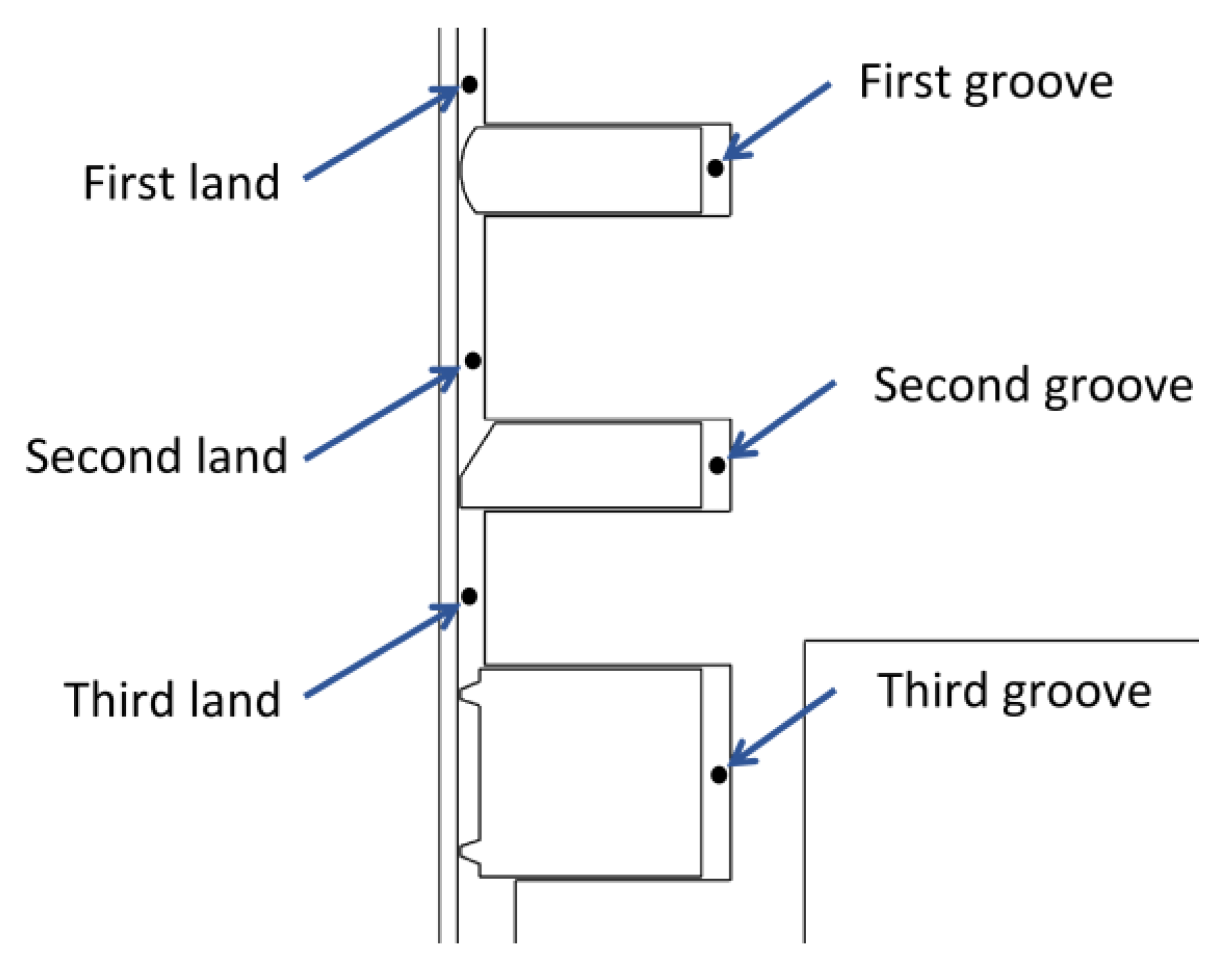
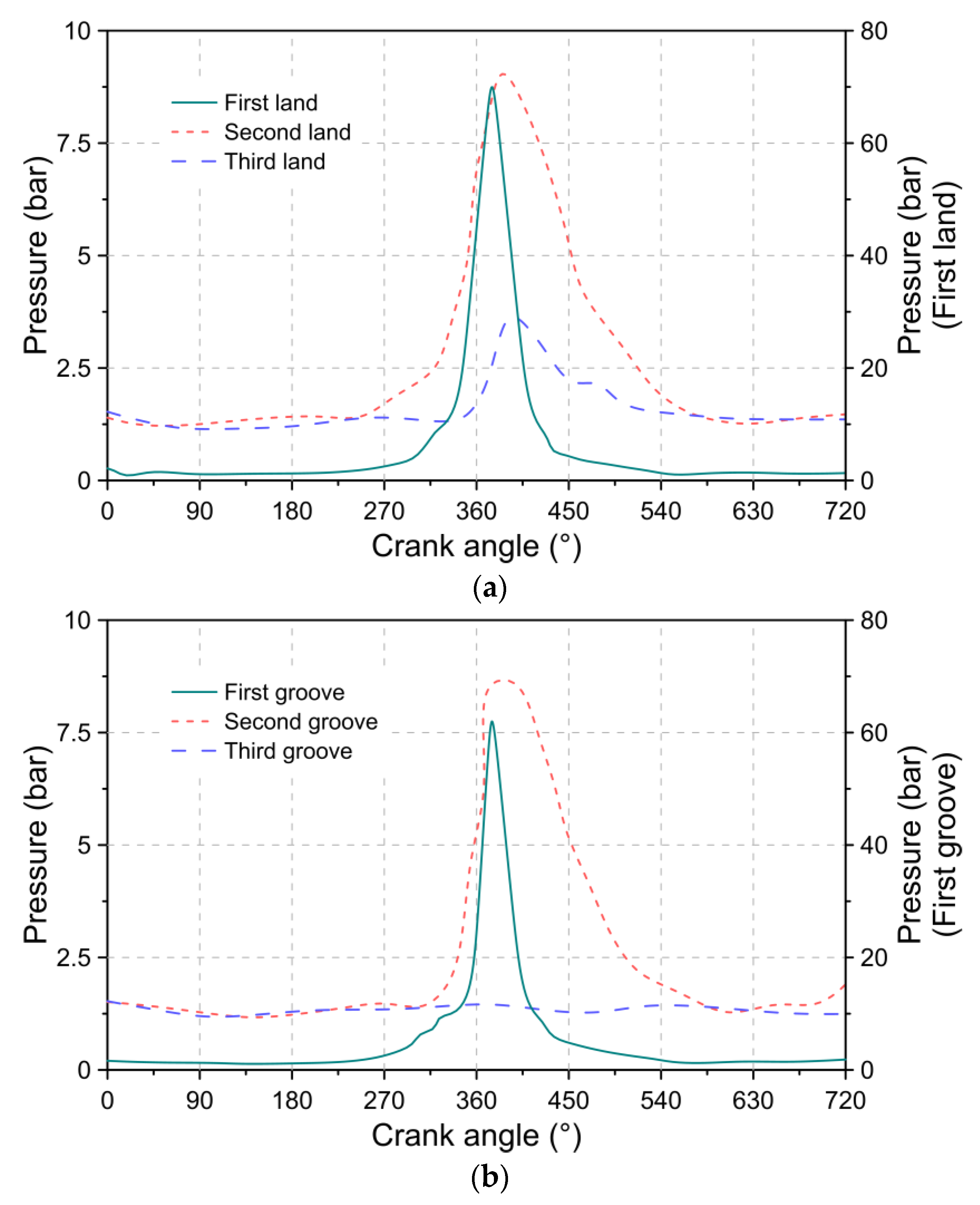
Figure 10 shows the locations of the lands and grooves in the piston body. From these locations, the pressure conditions are analyzed. The results obtained are described in Figure 11.
According to the results of Figure 11, it was observed that during the compression and expansion stage, the highest-pressure ranges are presented, reaching a maximum value of 9.0 and 3.6 bar for lands 2 and 3, and a maximum value of 8.7 and 1.5 bar for grooves 2 and 3, respectively. The higher-pressure conditions in the compression and expansion stage are attributed to the increase in the concentration of gas flow due to the negative angle of inclination experienced by the first and second piston rings. The reduced pressure level in groove 3 is a consequence of its proximity to the engine crankcase, which is not directly affected by combustion phenomena. This allows us to explain the constant pressure levels at this location throughout the combustion cycle.

5.3. Leakage Flow Analysis

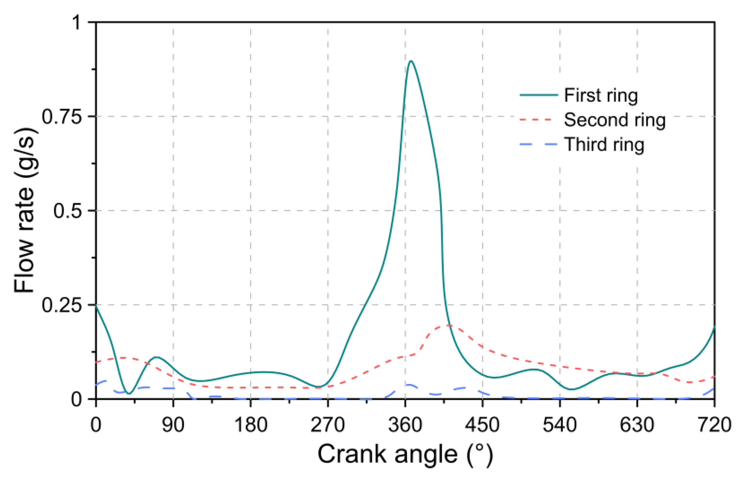
Figure 12 shows the flow conditions through the end gap of each ring as a function of the crankshaft angle.
From the results described in Figure 12, it is evident that the first ring has a significant impact on the amount of flow that the piston manages to pass through. This is because the gaps in the first ring interact directly with the combustion chamber. Therefore, the reduction in the gaps of the first ring is a key factor in limiting the leakage of gases. The highest levels of leakage for the simulated conditions were 0.90, 0.20, and 0.05 g/s in the first, second, and third rings, which occurred between the transition from the compression stage to the expansion stage. Additionally, a high flow condition was observed during the admission stage in the third ring, which registered a maximum of 0.046 g/s. This may be a consequence of the increase in pressure on earth three, as indicated in Figure 11. This implies that the pressure force on the ring manages to overcome the inertia of the ring, preventing it from settling on its upper surface and, hence, allowing the flow to pass.

5.4. Analysis of Power Loss in the Piston Rings

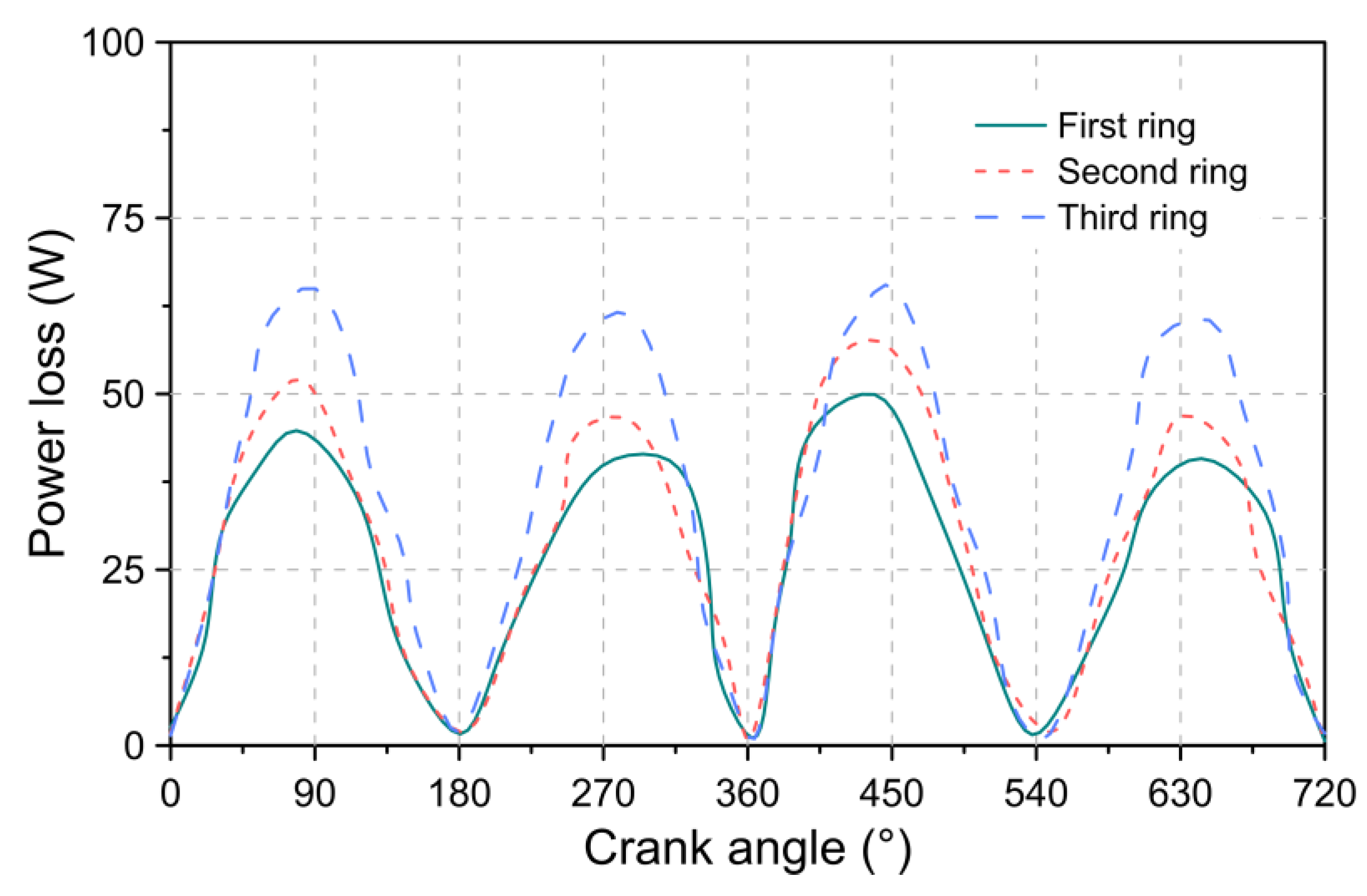
The power loss to friction between the cylinder liner and the surface of each of the rings is shown in Figure 13. This analysis is carried out under a condition of the rotation speed of 2000 rpm. For the power loss analysis, the energy dissipated in the three piston rings is taken into consideration.
The results obtained indicate that the highest friction losses occur in the third ring, followed by the second and first rings, respectively. This behavior can be a consequence of the beveled edge, which prevents the ring from buoyancy in the piston groove. However, this favors the presence of a mixed friction condition. Additionally, the tension of this ring is the strongest for its work to control the oil distribution. In general, the losses in the first and second rings are 23.6% and 11.7% lower compared to the third ring.
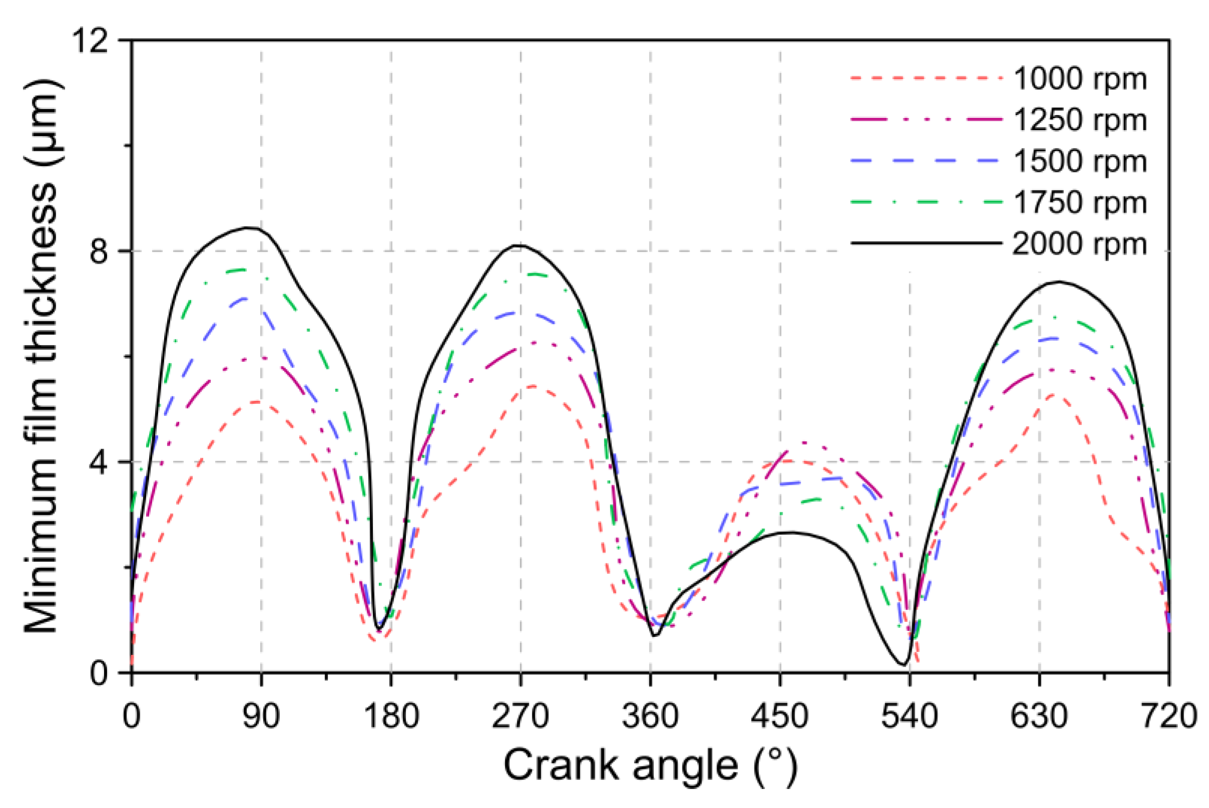
Figure 14 indicates the thickness of the lubrication film for different conditions of motor rotation speed. The results obtained show that the minimum lubrication thicknesses are present at the bottom dead center. Therefore, this piston location is the most prone to severe wear on the cylinder liner. In general, the highest lubrication film thickness values are observed at the highest rotational speed conditions. However, this behavior is reversed during the expansion stage (360–540°). This can be attributed to the mixed lubrication condition aggravated by the increase in piston speed.
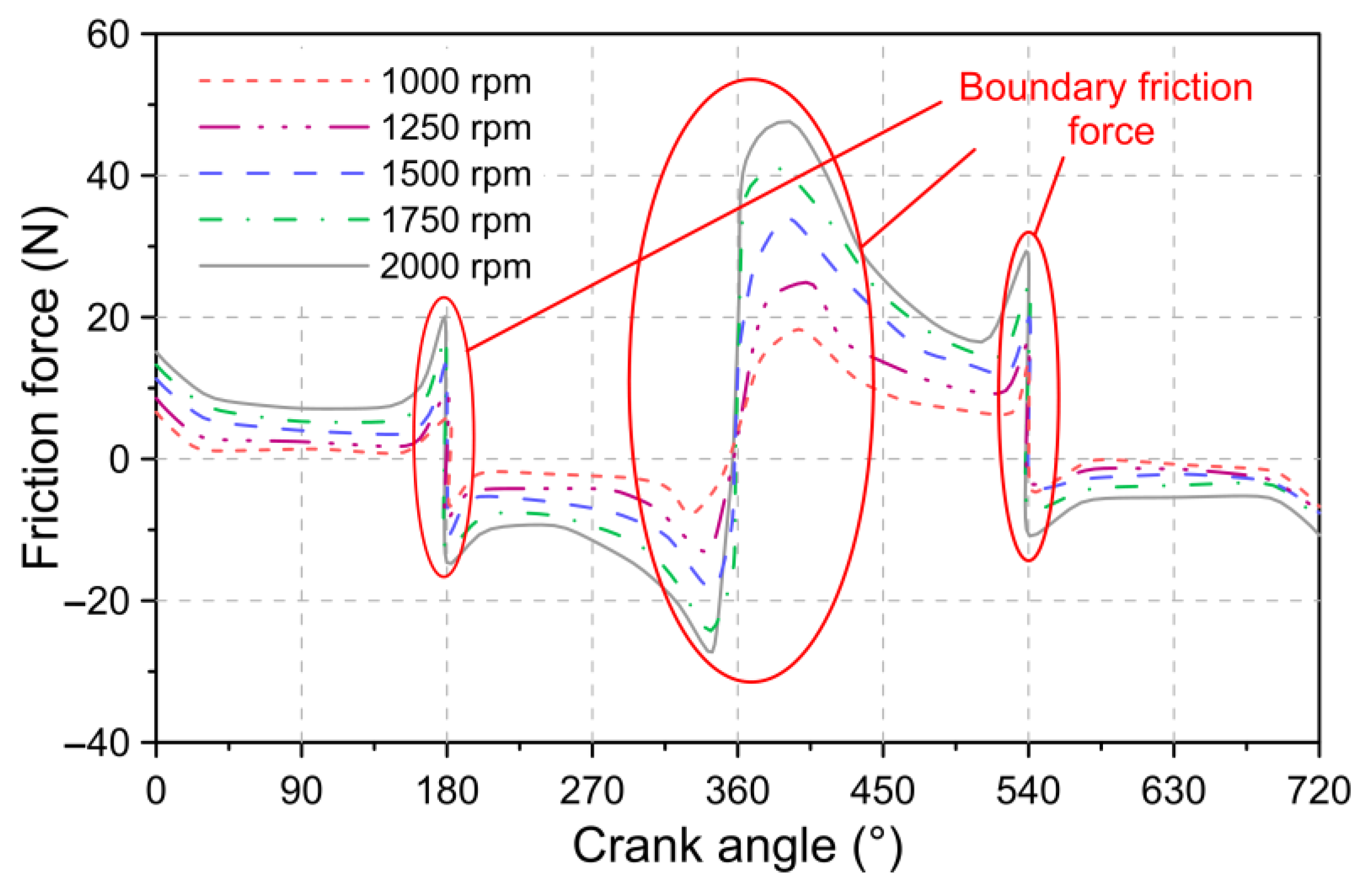
In Figure 15 the influence of the speed of rotation of the motor on the friction force of the piston is described. The results show that the greatest friction force occurs approximately during the beginning of the expansion stage, which may be a consequence of the critical thinning of the lubrication film, as indicated in Figure 14. The maximum friction force for the speeds of 1000, 1250, 1500, 1750, and 2000 rpm were 19, 25, 34, 40, and 47 N, respectively. The above results show that the greatest friction force occurs at the highest rotational speed. This behavior can be attributed to the greater thickness of the lubrication film, as indicated in Figure 14. Additionally, the increase in the speed of rotation implies an increase in the speed of the piston. Both factors favor the increase in the friction force, as indicated in Equations (8)–(10).
Figure 16 shows the percentages of energy loss as a consequence of the friction of the rings on the cylinder liner and gas leaks for different conditions of rotational speeds at a constant load of 408 Nm.
The results obtained show that the losses due to gas leakage are higher compared to the friction losses. As the rotation speed increased, there was an increase in both types of losses. For the simulated conditions, it was evidenced that leakage losses range between 3.22–7.90%, respectively. In the case of friction losses, a loss percentage between 2.67–8.29% was observed.

6. Conclusions

In this research, an analysis of the kinematic and dynamic characteristics of the piston ring package of a diesel engine is carried out through the integrated development of CFD simulation with mathematical models, in which the effects of temperature on the properties of the oil are considered. The kinematic movement of the piston, the friction force, and the leakage of gases in the combustion chamber. Next, the conclusions obtained from the kinematic analyzes, pressure conditions, and energy losses are indicated.
The kinematic analysis of the three piston rings allowed the evaluation of the radial and axial movement and the angle of inclination that the rings present throughout the combustion cycle. In which, it was evidenced that the first ring has a considerably greater radial and axial movement compared to the other piston rings. This greater instability of the ring in the piston groove tends to favor the amount of leakage gases. Additionally, it was shown that the first and second rings tend to maintain a negative tilt angle throughout the combustion cycle, which facilitates the advancement of the combustion gases over the piston grooves. Due to the above, it is necessary to use strategies such as the application of static torsions in the rings so that they tend to maintain a positive inclination.
The analysis of pressure conditions allowed to show that the maximum pressure of the earth and groove of the second ring is 150% and 480% higher compared to the conditions present in the third ring. Due to these high pressures, it is necessary to focus efforts on the design of the profile of this ring, given its importance to control the exhaust gases towards the engine crankcase, especially during the compression and expansion stages.
The analysis of energy losses showed that the combination of leakage gases and friction are responsible for a mechanical loss between 6–16%. These losses are significantly high under conditions of high engine rotation speed. Both types of losses presented similar percentages for the range of speeds analyzed. Therefore, leak mitigation plays an important role in improving the performance and emissions of internal combustion engines.
In general, the development of the proposed methodology is a novel tool for the joint analysis of the kinematic characteristics, pressure conditions, and energy losses. In this way, integrated analysis of changes caused by piston ring designs is possible.
The development of future research will be focused on the integration of additional mathematical models that allow taking into account other parameters, such as deformation and torsion experienced by the rings during the combustion cycle.

Author Contributions

Conceptualization, W.O.L.; methodology, W.O.L.; software, W.O.L.; validation, W.O.L., M.D.S.F.-V. and J.P.-L.; formal analysis, W.O.L., M.D.S.F.-V. and J.P.-L.; investigation, W.O.L., M.D.S.F.-V. and J.P.-L.; resources, W.O.L., M.D.S.F.-V. and J.P.-L.; writing—original draft preparation, W.O.L.; writing—review and editing, M.D.S.F.-V. and J.P.-L.; funding acquisition, W.O.L., M.D.S.F.-V. and J.P.-L. All authors have read and agreed to the published version of the manuscript.

Funding

This research was supported by the Universidad Francisco de Paula Santander located in Cúcuta, Colombia and the Universidad Antonio Nariño located in Barranquilla, Colombia.

Institutional Review Board Statement

Not applicable.

Data Availability Statement

Data sharing not applicable.

Acknowledgments

The authors would like to acknowledge the Universidad Francisco de Paula Santander and Universidad Antonio Nariño for their support in the development of this investigation.

Conflicts of Interest

The authors declare no conflict of interest.

Abbreviations

The following abbreviations are used in this manuscript:
Nomenclature
l c Length of the crankshaft
l r Length of the connecting rod
v p Piston velocity
a p Piston acceleration
c t h Coefficient of thermal expansion
Z Lubricant piezo-viscosity index
S o Thermo-viscosity index
α o Atmospheric piezo-viscosity coefficient
β o Thermo-viscosity coefficient
f c Contact friction force
f v Viscous friction force
f a Asperity friction force
τ Viscous shear stress of the lubricating oil
A Apparent contact area
A e Real contact area between ring and liner
h Lubricant film thickness
W l Asperity contact load
F 2 ( λ ) Statistical function
c d Coefficient of discharge
T u Orifice upstream temperature
A r Ring end-gap area
R Gas constant
f m Compressibility factor
P u Upstream pressure
P d Downstream pressure
r s Ratio of specific heats
h Thickness of the lubrication film
p Pressure between the ring surface and the cylinder liner
Greek Letters
τ o   Limiting Eyring shear stress
κ Average radius of curvature of asperities
ξ Density of asperity peaks per unit area
σ Surface roughness
λ Stribeck lubricant film ratio
μ Dynamic viscosity of the lubricating oil
β Angle between the connecting rod and the piston displacement axis
ω c Angular velocity of the crankshaft
ω r e l Relative angular velocity of the movement between connecting rod and piston
α r e l Relative acceleration of the movement between connecting rod and piston
ρ Density of the lubricating oil
ζ Coefficient of asperity shear strength

References

  1. Reitz, R.D.; Ogawa, H.; Payri, R.; Fansler, T.; Kokjohn, S.; Moriyoshi, Y.; Agarwal, A.K.; Arcoumanis, D.; Assanis, D.; Bae, C.; et al. IJER editorial: The future of the internal combustion engine. Int. J. Engine Res. 2020, 21, 3–10. [Google Scholar] [CrossRef] [Green Version]
  2. Patil, V.; Shastry, V.; Himabindu, M.; Ravikrishna, R.V. Life-cycle analysis of energy and greenhouse gas emissions of automotive fuels in India: Part 2—Well-to-wheels analysis. Energy 2016, 96, 699–712. [Google Scholar] [CrossRef]
  3. Correa, G.; Muñoz, P.M.; Rodriguez, C.R. A comparative energy and environmental analysis of a diesel, hybrid, hydrogen and electric urban bus. Energy 2019, 187, 115906. [Google Scholar] [CrossRef]
  4. Holmberg, K.; Erdemir, A. The impact of tribology on energy use and CO2 emission globally and in combustion engine and electric cars. Tribol. Int. 2019, 135, 389–396. [Google Scholar] [CrossRef]
  5. Söderfjäll, M.; Herbst, H.M.; Larsson, R.; Almqvist, A. Influence on friction from piston ring design, cylinder liner roughness and lubricant properties. Tribol. Int. 2017, 116, 272–284. [Google Scholar] [CrossRef]
  6. Rahmani, R.; Rahnejat, H.; Fitzsimons, B.; Dowson, D. The effect of cylinder liner operating temperature on frictional loss and engine emissions in piston ring conjunction. Appl. Energy 2017, 191, 568–581. [Google Scholar] [CrossRef] [Green Version]
  7. Schommers, J.; Scheib, H.; Hartweg, M.; Bosler, A. Minimising friction in combustion engines. MTZ Worldw. 2013, 74, 28–35. [Google Scholar] [CrossRef]
  8. Gore, M.; Theaker, M.; Howell-Smith, S.; Rahnejat, H.; King, P.D. Direct measurement of piston friction of internal-combustion engines using the floating-liner principle. Proc. Inst. Mech. Eng. Part D J. Automob. Eng. 2014, 228, 344–354. [Google Scholar] [CrossRef] [Green Version]
  9. Hanke, W.; Ando, H.; Fahr, M.; Voigt, M. Friction Reduction in Power Cylinder Systems for Pass enger Car Diesel Engines. MTZ Worldw. 2014, 75, 26–31. [Google Scholar] [CrossRef]
  10. Koszalka, G.; Hunicz, J. Comparative study of energy losses related to the ring pack operation in homogeneous charge compression ignition and spark ignition combustion. Energy 2021, 235, 121388–121399. [Google Scholar] [CrossRef]
  11. Turnbull, R.; Dolatabadi, N.; Rahmani, R.; Rahnejat, H. An assessment of gas power leakage and frictional losses from the top compression ring of internal combustion engines. Tribol. Int. 2020, 142, 105991. [Google Scholar] [CrossRef]
  12. Bolander, N.W.; Steenwyk, B.D.; Kumar, A.; Sadeghi, F. Film thickness and friction measurement of piston ring cylinder liner contact with corresponding modeling including mixed lubrication. In Proceedings of the Internal Combustion Engine Division Fall Technical Conference, Long Beach, CA, USA, 24–27 October 2004; Volume 37467, pp. 811–821. [Google Scholar]
  13. Avan, E.Y.; Spencer, A.; Dwyer-Joyce, R.S.; Almqvist, A.; Larsson, R. Experimental and numerical investigations of oil film formation and friction in a piston ring–liner contact. Proc. Inst. Mech. Eng. Part J J. Eng. Tribol. 2013, 227, 126–140. [Google Scholar] [CrossRef]
  14. Zavos, A.; Nikolakopoulos, P.G. Tribology of new thin compression ring of fired engine under controlled conditions-A combined experimental and numerical study. Tribol. Int. 2018, 128, 214–230. [Google Scholar] [CrossRef]
  15. Koszalka, G. The use of the gas flow model to improve the design of the piston-rings-cylinder system of a diesel engine. In Proceedings of the IOP Conference Series: Materials Science and Engineering, Kragujevac, Serbia, 5–7 September 2019; Volume 659, p. 12072. [Google Scholar]
  16. Oliva, A.; Held, S. Numerical multiphase simulation and validation of the flow in the piston ring pack of an internal combustion engine. Tribol. Int. 2016, 101, 98–109. [Google Scholar] [CrossRef]
  17. Skoblo, T.S.; Sidashenko, A.I.; Satanovskii, E.A.; Oleinik, A.K.; Mal’tsev, T.V. Specific Features of Wear of Oil-Scraper Piston Rings with Tin Coatings in Bench Tests for Friction and Wear. Mater. Sci. 2018, 53, 501–507. [Google Scholar] [CrossRef]
  18. Niralgikar, K.H.; Bulsara, M.A. Investigation of Wear Pattern in Piston Ring of an IC Engine. Tribol. Ind. 2019, 41, 100–108. [Google Scholar] [CrossRef]
  19. Delprete, C.; Razavykia, A.; Baldissera, P. Detailed analysis of piston secondary motion and tribological performance. Int. J. Engine Res. 2020, 21, 1647–1661. [Google Scholar] [CrossRef]
  20. Delprete, C.; Razavykia, A. Piston ring--liner lubrication and tribological performance evaluation: A review. Proc. Inst. Mech. Eng. Part J J. Eng. Tribol. 2018, 232, 193–209. [Google Scholar] [CrossRef]
  21. Delprete, C.; Razavykia, A. Statistical Study of Ring Geometry Effect on Piston Ring/Liner Tribology Using Classical Design of Experiment; SAE Technical Paper; SAE International: Warrendale, PA, USA, 2018. [Google Scholar]
  22. Baker, C.; Theodossiades, S.; Rahmani, R.; Rahnejat, H.; Fitzsimons, B. On the Transient Three-Dimensional Tribodynamics of Internal Combustion Engine Top Compression Ring. J. Eng. Gas Turbines Power 2017, 139, 062801. [Google Scholar] [CrossRef]
  23. Xu, Y.; Zheng, Q.; Geng, J.; Dong, Y.; Tian, M.; Yao, L.; Dearn, K.D. Synergistic effects of electroless piston ring coatings and nano-additives in oil on the friction and wear of a piston ring/cylinder liner pair. Wear 2019, 422, 201–211. [Google Scholar] [CrossRef]
  24. Peng, Y.; Xu, Y.; Geng, J.; Dearn, K.D.; Hu, X. Tribological assessment of coated piston ring-cylinder liner contacts under bio-oil lubricated conditions. Tribol. Int. 2017, 107, 283–293. [Google Scholar] [CrossRef]
  25. Perera, M.S.M.; Theodossiades, S.; Rahnejat, H. Elasto-multi-body dynamics of internal combustion engines with tribological conjunctions. Proc. Inst. Mech. Eng. Part K J. Multi-Body Dyn. 2010, 224, 261–277. [Google Scholar] [CrossRef] [Green Version]
  26. Dowson, D.; Higginson, G.R. A Numerical Solution to the Elasto-Hydrodynamic Problem. J. Mech. Eng. Sci. 1959, 1, 6–15. [Google Scholar] [CrossRef]
  27. Houpert, L. New Results of Traction Force Calculations in Elastohydrodynamic Contacts. J. Tribol. 1985, 107, 241–245. [Google Scholar] [CrossRef]
  28. Rahnejat, H. Tribology and Dynamics of Engine and Powertrain: Fundamentals Applications and Future Trends; Woodhead Publishing: Cambridge, UK, 2010. [Google Scholar]
  29. Rahmani, R.; Theodossiades, S.; Rahnejat, H.; Fitzsimons, B. Transient elastohydrodynamic lubrication of rough new or worn piston compression ring conjunction with an out-of-round cylinder bore. Proc. Inst. Mech. Eng. Part J J. Eng. Tribol. 2012, 226, 284–305. [Google Scholar] [CrossRef] [Green Version]
  30. Teodorescu, M.; Taraza, D.; Henein, N.A.; Bryzik, W. Simplified Elasto-Hydrodynamic Friction Model of the Cam-Tappet Contact; SAE Technical Paper; SAE International: Warrendale, PA, USA, 2003. [Google Scholar]
  31. Teodorescu, M.; Balakrishnan, S.; Rahnejat, H. Integrated Tribological Analysis within a Multi- physics Approach to System Dynamics. Tribol. Interface Eng. Ser. 2005, 48, 725–737. [Google Scholar] [CrossRef]
  32. Theaker, M.; Rahmani, R.; Rahnejat, H. Prediction of Ring-Bore Conformance and Contact Condition and Experimental Validation. In Proceedings of the ASME 2012 Internal Combustion Engine Division Spring Technical Conference, Turin, Italy, 6–9 May 2012; American Society of Mechanical Engineers: New York, NY, USA, 2012; pp. 885–892. [Google Scholar]
  33. Woods, W.A. On the role of the harmonic mean isentropic exponent in the analysis of the closed-cycle gas turbine. Proc. Inst. Mech. Eng. Part A J. Power Energy 1991, 205, 287–291. [Google Scholar] [CrossRef]
  34. Jeng, Y.-R. Theoretical Analysis of Piston-Ring Lubrication Part I—Fully Flooded Lubrication. Tribol. Trans. 1992, 35, 696–706. [Google Scholar] [CrossRef]
  35. Priest, M.; Dowson, D.; Taylor, C.M. Theoretical modelling of cavitation in piston ring lubrication. Proc. Inst. Mech. Eng. Part C J. Mech. Eng. Sci. 2000, 214, 435–447. [Google Scholar] [CrossRef]
  36. Popoola, O.; Cao, Y. The influence of turbulence models on the accuracy of CFD analysis of a reciprocating mechanism driven heat loop. Case Stud. Therm. Eng. 2016, 8, 277–290. [Google Scholar] [CrossRef] [Green Version]
Figure 1. Geometric profile of the (a) first ring, (b) second ring, and (c) third piston ring.
Lubricants 09 00116 g001
Figure 2. Kinematic model of piston assembly.
Lubricants 09 00116 g002
Figure 3. Test engine piston geometry.
Lubricants 09 00116 g003
Figure 4. Research methodology using CFD.
Lubricants 09 00116 g004
Figure 5. Comparison of pressure conditions between numerical simulation and experimental data.
Lubricants 09 00116 g005
Figure 6. Radial movement of piston rings.
Lubricants 09 00116 g006
Figure 7. Axial movement of piston rings.
Lubricants 09 00116 g007
Figure 8. Tilting angle piston rings.
Lubricants 09 00116 g008
Figure 9. Tilt type in piston ring, (a) positive and (b) negative.
Lubricants 09 00116 g009
Figure 10. Location of the lands and grooves in the piston body.
Lubricants 09 00116 g010
Figure 11. Pressure conditions at piston locations (a) lands and (b) grooves.
Lubricants 09 00116 g011
Figure 12. Mass flow rates in the rings end gaps.
Lubricants 09 00116 g012
Figure 13. Power loss in piston rings.
Lubricants 09 00116 g013
Figure 14. Minimum lubrication film thickness for different rotation speeds (compression ring).
Lubricants 09 00116 g014
Figure 15. Friction force for different rotational speeds (compression ring).
Lubricants 09 00116 g015
Figure 16. Piston energy distribution.
Lubricants 09 00116 g016
Table 1. Technical characteristics of the test engine.
ModelReference 4JJ1
ManufacturerISUZU
Engine type4 cylinders
Bore95.4 mm
Stroke104.9 mm
Compression ratio17.5:1
Injection systemDirect injection
Displaced volume2999 cc
Cycle4 Strokes
Table 2. Technical characteristics of the test engine.
PropertiesUnitSAE 10W40
Kinematic viscosity (40 °C)m2/s 91.057 × 10 6
Density (40 °C)kg/m3866
Flash point°C230
Dynamic viscosity (40 °C)m2/s 105.10 × 10 6
Pressure—viscosity coefficientm2/N 1 × 10 8
Table 3. Pressure conditions for blow-by model.
Crankshaft Angle (°)Pressure (bar)
First LandSecond LandThird LandCrankcase
02.431.401.530.08
451.941.251.230.11
901.571.281.140.09
1351.681.401.150.10
1801.551.441.180.07
2252.031.401.240.08
2702.881.771.350.09
3157.742.461.310.13
36044.026.721.730.15
40522.828.433.510.16
4504.435.052.190.11
4953.083.201.860.14
5401.491.901.460.07
5851.851.381.440.08
6301.841.231.350.10
6752.081.361.300.07
7201.951.501.330.09
Publisher’s Note: MDPI stays neutral with regard to jurisdictional claims in published maps and institutional affiliations.