Abstract
Friction-induced vibrations (brake squeal) produced during braking applications have been one of the major problems in the transportation for many years. It can be the most troublesome for passengers because of its high frequency and acoustic pressure. The role of frictional contact surface geometry on the occurrence of squeal was investigated recently by some researchers. However, it has never been systematically studied at different scales simultaneously. Contact localizations are induced on the one hand by macro effects such as thermal dilatation (macroscopic scale) and on the other hand, by the heterogeneity of third body (tribolayer) generated by friction (mesoscopic scale). The aim of this paper is to investigate the effect of contact localization at both scales through stability analysis on a simplified pad on disc system. The model has been developed numerically by the finite element method (FEM) to introduce a non-uniform contact at macroscopic and mesoscopic scales. The results showed a strong dependency between squeal frequencies and effective contact zone at macroscopic and mesoscopic scales for the investigated configuration. Especially, it is found that squeal frequencies depend on the contact area at a macroscopic scale whereas the probability of occurrence of squeal frequency strongly relies on mesoscopic contact distribution.
1. Introduction
Brake squeal has been a problem in the automotive industry for many years. It can be the most troublesome for passengers because of its high frequency and acoustic pressure (above 1 kHz and 80 dB) [1]. Although, various research and development efforts in experiments and numerical modeling have been made, a complete understanding of the behavior of the friction interface is a difficult task. It is due to multi-physical phenomena modifying the contact conditions during squeal such as applied pressure [2], humidity [3], thermal effect [4], tribology [5,6], wear [7,8] and friction coefficient between two facing surface of the pad and the disc [9]. It is well accepted that brake squeal is affected by many different phenomena at different scales.
The effect of contact surface geometry on squeal occurrence has been studied at different scales. From the literature, three scales can be distinguished. At microscopic scale (level of asperities), works in [10,11,12,13] investigated the influence of surface topography on squeal occurrence. The height distribution of asperities reportedly affects the tangential contact stiffness and can lead to self-excited vibration. Magnier et al. [14] proposed an analytical model with a contact interface including stiffness heterogeneities between pad and disc and demonstrated the influence of these kinds of heterogeneities on mode lock-in. They found that if the size of heterogeneities is large, the effect of contact localization is important. When the size of heterogeneities decreases, the phenomenon of contact localization is less important and is similar to that obtained in the homogeneous case. At a larger scale (mesoscopic scale), considering that friction material is heterogeneous, on the sliding surface, the evolution of contact surface heterogeneity (wear debris compaction around hard ingredients and apparition of tribological circuit) produces the tribological layer made of powders and plateaus [5]. These plateaus play an important role on the occurrence of squeal [9,15,16,17,18,19]. It is reported that the size and distribution of contact plateaus are closely associated with squeal tendency. It is consequently suggested that the occurrence of friction-induced vibration can be controlled by monitoring the size and distribution of contact plateaus on the friction material surface. Recently, Singla et al. [6] observed experimentally that in a noisy tribosystem, the contact localization is changed by the redistribution of third body particles in the interface. This contact localization is different from the initial one of the silent tribosystem. On the other hand, at the scale of global contact area (macroscopic scale), the effect of pad geometry on squeal occurrence have been studied in [20,21]. It is stated that the occurrence of brake noise is strongly affected by pad contact surface and may be reduced if the nominal contact surface is divided by 2. More especially, the noise level was reportedly reduced only when material was removed at the leading and trailing edges of the pad. These observations lead to technological solutions to reduce squeal occurrence such as chamfering the brake pad or adding slots. Abu Bakar [22] found that wear increases the contact area and can trigger squeal. Naidoo Ramasami [23] and Duboc et al. [21] investigated the effect of pad geometry on the variation of squeal frequency. From these studies, it leads to a question of the relationship between contact surface localization and the occurrence of squeal.
Actually, it is well accepted by the scientific community that squeal is a result of unstable frictional dynamic behavior of mechanical system. Triggering mechanisms have been proposed to explain the type of instability and can be distinguished in two categories. The first approach relies on friction coefficient variation with relative sliding speed. It corresponds to stick-slip mechanism [24,25,26,27] triggered by the difference between static and dynamic friction coefficient and negative damping triggered by the decrease of friction coefficient as a function of relative sliding speed [28]. Although Jarvis et al. [28] realized that the variation of the friction was not the only root cause and was insufficient to cause friction-induced vibrations, this stick-slip mechanism is still used to explain brake vibration problems [18]. Moreover, from experimental point of view, only the apparent friction coefficient can be measured and the local friction coefficient is not accessible. Unlike the first approach, for the second approach, which relies on the geometry coupling of the mechanical system through friction coefficient, instabilities can occur with a constant friction coefficient. This second approach includes sprag-slip [29] and mode coupling [28,30,31]. Sprag-slip relates to system dynamic behavior at low frequency and mode coupling relates its dynamic behavior at at relative high frequency. Considering mode-coupling as instability mechanism, a complex modal analysis of the mechanical system can be performed to evaluate the complex modes. Unstable modes are identified with a positive real part of the corresponding complex eigenfrequencies. As mentioned by many authors (cf. [32] for instance), the complex eigenvalue problem may overestimate or underestimate the number of unstable modes. Transient analysis, which allows for the introduction of nonlinearities related to the contact evolution at the frictional interface can achieve stability analysis. However for a large number of simulations, transient analysis proves to be very expensive on computational time. Mode-coupling mechanism is used in many numerical models of brake squeal [14,22,23,33,34,35]. Several system parameters influence mode-coupling such as friction coefficient [31], structural damping [36], geometry and contact between the components of a brake system [37,38] or the length of sliding contact zone [21].
Comparing numerical and experimental results, [35] showed that numerical analysis may underestimate unstable frequencies if the contact between the pad and the disc is considered as perfectly flat and homogeneous. The aim of this paper is to investigate the effect of contact localizations at macroscopic and mesoscopic scales on mode-coupling instabilities though stability analysis. The FEM model is based on the set-up developed in [21] that allows studying the role of the interface behavior on squeal generation. Friction coefficient is assumed to be constant. Although it is well known that friction material is heterogeneous, it is assumed homogeneous to facilitate the study of the effect of contact localization. Stability analysis for uniform contact zone is firstly performed in order to validate this model. The effect of macroscopic contact localizations is then investigated by varying the localization and dimensions of effective contact zones. Finally, the effect of contact localizations at mesoscopic scale is studied by creating random distribution of plateaus on macroscopic contact zone.
2. Complex Modal Analysis of a Simplified Pin on Disc System
2.1. Finite Element Model
The FE model of the pin on disc system is described in Figure 1. A thin plate is fixed on a rigid stand (red surface of the thin plate). The pin, extracted from a brake pad is glued at the center of the thin plate. A displacement of a rigid stand along the axial disc direction pushes the pin against the disc and a normal load is obtained with the bending of the thin plate. A thick plate is added on the plate over the pin to insert displacement sensors measuring pin vibration shape. The average radius of the friction track is 100 mm. The sliding contact area is a 20 × 20 mm2. Material behaviors of the disc, the thin plate and the thick plate are isotropic while the material behavior of the pad is transversal isotropic. The material data is given in Table 1. A fine mesh is used (Figure 1b) which leads to a total number of degrees of freedom n = 300,000 and a number of contact nodes nc = 441. The mesh is compatible, meaning that there are two facing nodes of the disc and pad which have the same (x,y) coordinates at the contact zone. A fixed boundary condition is assumed for the external face of the disc and the thin plate (red surfaces).
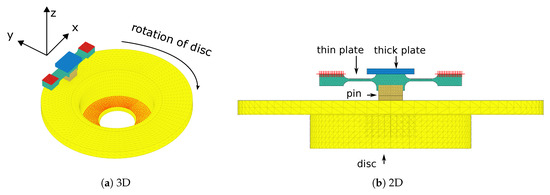
Figure 1.
FEM model of the pin on disc system used for stability analysis.

Table 1.
Material data.
The normal modes for the disc and the pad are computed and then compared to the measured frequencies. For the disc with free boundary conditions on the contact surface, 27 normal modes are computed up to 10 kHz. Three mode types are distinguished (Table 2): axial modes (a,m,n) for which axial deformations are dominant (out-of-plane modes); the radial modes (r,n) for which radial deformations are dominant (in-plane) and the circumferential modes (c,m,n) for which circumferential deformations are dominant (in plane modes). (a,r,c) denote the axial, radial and circumferential dominant deformations, respectively. (m,n) denotes the number of nodal circle and diameter, respectively. The difference between the FE frequencies and the measured ones are less than 4.5% as shown in Figure 2a. Similarly, for the pin, 6 normal modes are computed up to 10 kHz. As in [21], only three first frequencies of the pad are measured because the pad deformed shape is harder to identify at a higher frequency as the amplitudes are lower. The difference between the FE frequencies and the measured ones are less than 6.7% as shown in Figure 2b. The three pin modes shapes are illustrated in Figure 3.
Table 2.
Disc FE frequencies.
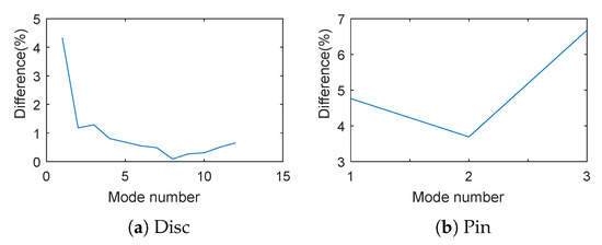
Figure 2.
Difference between FE and measured frequencies.
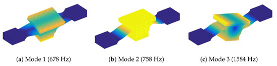
Figure 3.
Pin modes shape.
As in [39,40], by using a finite element model with compatible linear meshes at the interface, a discrete form of the equation of motion may be written as follows:
where U is the displacement vector. M and K denote the mass and stiffness matrices of the uncoupled system, C is the damping matrix associated to the viscous contact damping. In addition, and denote the normal and tangential reaction forces at the contact nodes along the directions n and t, and and are the projection matrices on the relative displacements between the disc and the pads along the same directions. F denotes the nodal vector of the external forces.
2.2. Stability Study by Complex Eigenvalue Analysis
Stability analysis aims to study the dynamic behavior of mechanical system affected by frictional contact through the determination of the evolution of small perturbations around the steady sliding equilibrium. The full sliding steady equilibrium is computed by using the algorithm developed by Lorang [33]. This quasi-static equilibrium is obtained by neglecting the dynamic terms in Equation (1) and by using an iterative fixed point algorithm on equivalent contact reactions and friction forces for the nonlinear resolutions. In unstable cases, some perturbations tend to diverge which can lead to self-sustained vibrations. Such an analysis is performed by a linearization of the non-linear equations around the steady sliding equilibrium. Searching a discrete solution of the form where stands for the complex displacement vector corresponding to small harmonic perturbations around the equilibrium, the linearized form of Equation (1) gives:
where are new projections matrices such that is the restriction of on nodes in the effective contact region at equilibrium and is the restriction of on components in direction t on nodes in the effective contact region. means that there is no detachment in the effective contact region. Modes corresponding to eigenvalues with positive real part are unstable. The divergence rate of a mode is defined as:
where are respectively the real and imaginary parts (pulsation) of the mode.
After some algebraic manipulations, Equation (2) leads to a constrained non symmetric eigenvalue problem:
where are non-symmetrical matrices taking into account the effects of the friction forces:
and a basis for the kernel of the normal contact constraints .
It is worth noting that this FE model has a large size (300,000 DoFs), reduction methods are therefore a necessity for the resolution of Equation (4). The principle is to search an approximated solution of the problem spanned by a reduced basis B, leading to a reduced dynamics equation. In any case, B is computed using iterative methods, such as widespread iterative algorithms based on Arnoldi process [41] or the residue iterative method [42]. However, the computational time is still expensive. Fixed reduced real bases [33,39,40] can overcome this difficulty. This basis, which is composed by real coupled basis enriched by the static part of the friction force, performed well in [40] compared to the residue iterative method [42].
2.3. Numerical Application: Uniform Zone Contact
The main aim of this application is to illustrate the method adopted in the previous section. In this case, it is assumed that the contact zone is flat. A vertical displacement uz = 125 μm is applied on the red surface of the disc (Figure 1) to obtain a vertical resulting contact force of 200 N.
2.3.1. Quasi-Static Equilibrium
The distribution of nodal contact forces as a function of friction coefficient is presented in Figure 4. X relates to the length of the pin (20 mm) along the tangential direction and Y relates to to the length of the pin along the disc radius (also 20 mm from radii 95 to 115 mm). There is a classical tilting of the pin along the sliding direction with friction. By increasing the friction coefficient, the effective zone contact is reduced and localized more and more at the leading edge.
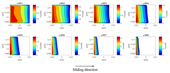
Figure 4.
Distribution of contact forces on the contact area as a function of friction coefficient.
2.3.2. Stability Analysis Results
Using Equation (4) together with enriched real coupled basis, the complex modes corresponding to these steady full sliding equilibriums are computed. Their frequencies and divergence rates as a function of friction coefficient are presented in Figure 5.
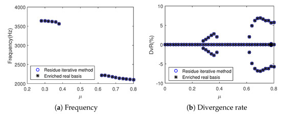
Figure 5.
Stability results in the case of uniform contact as a function of friction coefficient for the two computational methods.
Two unstable modes with positive real part of complex eigenvalue are found. The corresponding unstable frequencies are about 3500 Hz and 2100 Hz respectively. These unstable cases are denoted as coupling 1 and coupling 2 respectively. The unstable modes shapes are presented in Figure 6. These are the axial dominant movements with 3 or 4 nodal diameters and no nodal circle for the disc as well as rotational movement (tilting) of the pin. For the first unstable mode, friction coefficient varies between 0.28 and 0.38 at which the effective contact zone is large. For the second unstable mode, friction coefficient varies between 0.62 and 0.8 corresponding to a smaller effective contact zone. Concerning the performance of reduced bases, the results obtained with enriched real basis are similar to those obtained with residue iterative method. Thus, to reduce the computational time, enriched real basis are used for the following stability analyses.
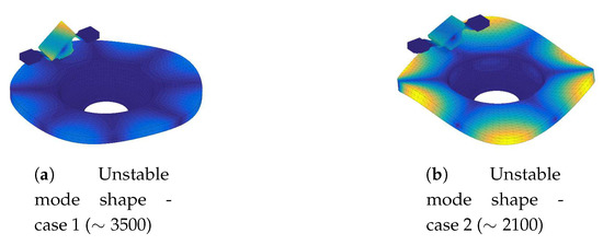
Figure 6.
Unstable modes shapes.
In order to find the contributions of free-interface normal modes in these unstable complex modes, the Normalized Modal Assurance Criterion (MAC) [40] between free-interface normal modes and these unstable complex modes is calculated. The expression of the MAC used here is given by Equation (6) in which is the unstable complex mode and is a free-interface normal mode. The axial dominant movement with no nodal circle for the disc and rotational movement for the pin contribute the most to these unstable frequencies as shown in Figure 7.
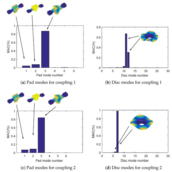
Figure 7.
MAC between free-interface normal modes and unstable complex modes.
In this section, considering that effective contact zone depends only on friction at contact zone, two unstable frequencies around 3500 Hz and 2100 Hz are found which will be called coupling 1 and coupling 2 respectively in the following.
2.4. Experimental Observations
Several friction tests have been performed at constant speed (200 or 500 revolutions per minute (rpm)) with an imposed displacement of the extremities of the thin plate leading to a normal contact force of 200 N during 30 s. The unstable frequencies found in the previous section are experimentally observed as shown in Figure 8. Harmonics are observed which are classically obtained due to contact nonlinearities. These instabilities have not been always observed but have occurred in the most cases. Squeal frequency at 3500 Hz is experimentally found when the rotation speed of the disc is 200 rpm while the one at 2100 Hz is found when the rotation speed is 500 rpm. In this case (500 rpm), apparent friction coefficient is lower than 0.5 (Figure 9). This means that the parametric study based on friction coefficient (Figure 5) can underestimate unstable configurations.
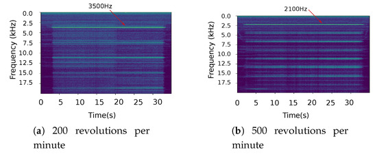
Figure 8.
Typical experimental spectrogram(time-frequency) of acoustic pressure as a function of the rotation speed of the disc.
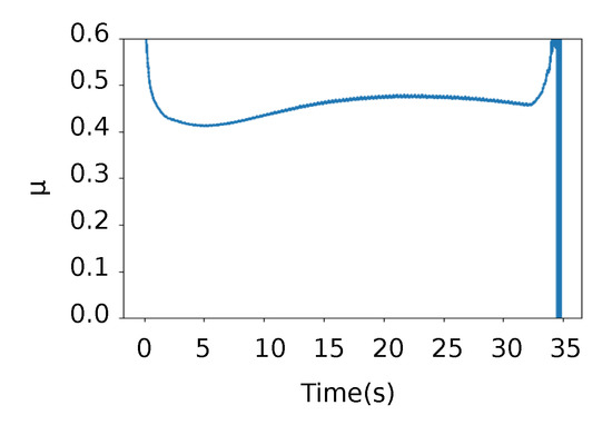
Figure 9.
Example of measured apparent friction coefficient (averaged value over 2 ms) at the speed of 500 rpm (coupling 2 at 2100 Hz).
In order to localize real contact zone, 8 thermocouples have been inserted in the pin at 2 mm depth from the sliding surface. By using inverse method applied to temperatures measured by these thermocouples [43], a macroscopic effective contact zone could be identified. Pictures of the surface have also been recorded between the tests to confirm these contact areas. With the two speeds (200 rpm and 500 rpm), two distinct macroscopic effective contact zones have been identified and are shown in Figure 10. Approximation of these effective areas has been done by superposing two experimental information not detailed here: image analysis (variations from successive ones) and thermal analysis (several thermocouples have been introduced in the pin and infrared measurements of the disc surface, allowing to approximate the heating areas). Note that the contact is not localized at the leading edge as in the numerical results of Figure 4 which is due to experimental initial conditions. These localizations appear almost systematically with speed variations. Localization around the pin center at high speed (500 rpm) can be explained by thermal dilatation which becomes dominant with a curved global shape of the pin when the temperature increases. This contact surface variation systematically leads to frequency shifting from 3500 Hz to 2100 Hz. Thus, it can be concluded that squeal frequency is correlated with specific contact zones.
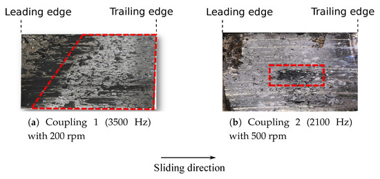
Figure 10.
Typical estimated macroscopic contact zone (inside dotted contour) from experiments for the 2 rotation speeds.
In fact, the effective contact zone depends not only on friction coefficient or dilatation but also on other phenomena. It is found in [22] that the effective contact zone always changes in terms of localization and dimensions due to wear even with the same friction coefficient. It depends also on kinematic parameters (for example: initial conditions of pad inclination in the sliding direction). From all these observations, it leads to a question of the effect of contact localization on the occurrence of squeal.
3. Influence of the Contact Distribution at Different Scales
The assumption of uniform contact can underestimate unstable frequencies [35]. Considering that the effective contact zone always changes during braking because of thermal effects, dilatation, wear, tribology, etc., the influence of contact distribution on squeal frequency needs to be analyzed. For this purpose, 2 scales are considered in the following: macroscopic and mesoscopic i.e., at the scale of global contact area and at the scale of the tribological layer made of powders and plateaus. It is assumed that effective contact zone is in full sliding state and its localization (position, dimensions) can be varied.
3.1. Macroscopic Scale
As mentioned in the previous section, the localization and dimensions of effective contact zone depend not only on friction but also on other phenomena such as thermal dilatation and wear. Since these phenomena always change, the localization and dimension of effective contact zone may vary. Their influence on the occurrence of squeal needs to be investigated. For this purpose, two assumptions are made. Firstly, there is a macroscopic contact zone in a rectangular form with a center point () and dimensions (a,b) as shown in Figure 11. By varying variables , different contact zones with different sizes are obtained. Secondly, all nodes at this macroscopic zone are in full sliding contact. Stability analysis are then performed for μ = 0.36. This study is highly larger than parametric study on friction coefficient because it takes into account all possible effective contact zones as a result of different phenomena (wear, dilatation, relative position between two facing surfaces and friction).
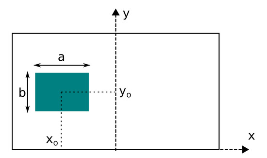
Figure 11.
Scheme of the macroscopic contact area with parameters.
At a position near the center of the nominal contact zone in Figure 12 only the a dimension varies, with a value of b = 14.2 mm and μ = 0.36. The increase of the length a of effective contact zone turns the unstable system from about 2100 Hz into 3500 Hz whereas only one unstable frequency at 3500 Hz appears in the case of flat contact surface. This result is similar to that obtained in [21]. More generally, by varying both a and b, Figure 13 shows that the squeal frequencies depend on both dimensions of effective contact zone while , are fixed. Results show that coupling 1 is obtained only with high contact areas of square shape while coupling 2 appears with medium size of rectangular to square shape.
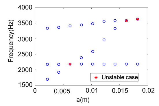
Figure 12.
Evolution of complex frequencies as a function of a while xo, yo are fixed (close to zero) and b = 14.2 mm.
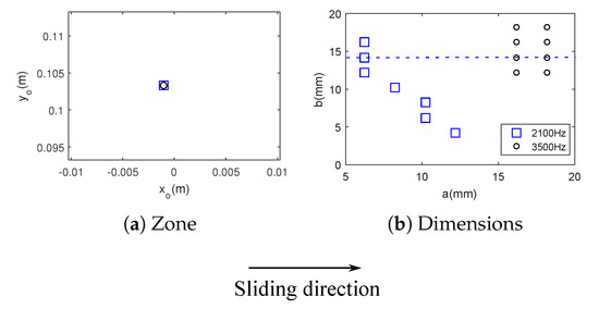
Figure 13.
Unstable frequencies when varying the size of the macroscopic zone, at centered localization (dotted line: reference data for results in Figure 12).
Figure 14 shows results for other positions. Several contact localizations can lead to system instabilities. The majority of effective contact zones for 2100 Hz are located near the leading edge. On the other hand, effective contact zone for 3500 Hz are localized around the center of the nominal contact zone. Figure 15 shows the surface area of effective contact zone for all the unstable cases as well as the effective contact zone corresponding to the biggest and smallest areas for two unstable cases. It is clear that effective contact zones for coupling 1 (3500 Hz) have larger size than those for coupling 2 (2100 Hz).
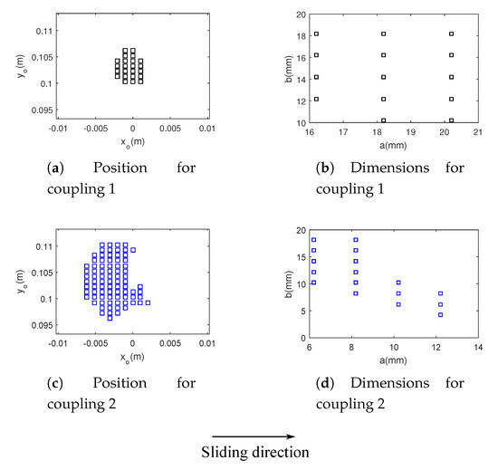
Figure 14.
Macroscopic zone for squeal frequencies for μ = 0.36.
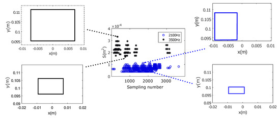
Figure 15.
Surface area of effective contact zone for all the unstable cases.
Figure 16 shows the influence of a larger friction coefficient (μ = 0.43) on the occurrence of instabilities. Effective contact zones for 3500 Hz still have larger size than those for 2100 Hz. The majority of contact localizations for unstable modes are almost similar (Figure 16a,c). The increase of friction coefficient makes the system unstable at more contact zones near the trailing edge (Figure 16c) and change the dimensions of contact localizations for coupling 2. This means that both friction coefficient and contact localization play a crucial role on mode-coupling instabilities.
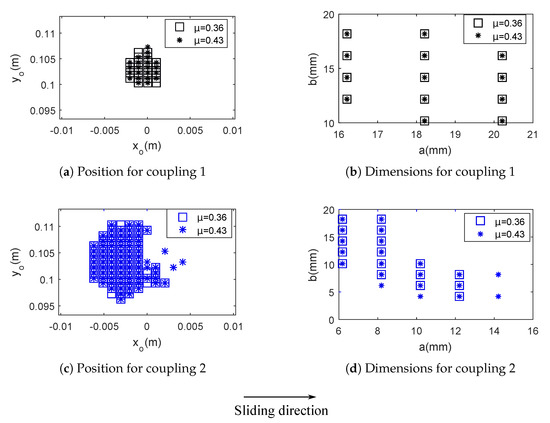
Figure 16.
Macroscopic zones of instabilities for two friction coefficients.
In this section, it is found that instabilities of the system depend not only on friction coefficient but also on the contact localization and on the size of effective contact zone. The change of unstable frequency can occur even at macroscopic scale. Thus, numerical simulation can underestimate unstable frequencies in the case of flat contact surface as observed in [35]. Instabilities at 3500 Hz can happen if effective contact zones are large whereas corresponding contact zone of instabilities at 2100 Hz are smaller and localized near the leading edge. These results are consistent with the experimental observations of Figure 10 and also with [23]. Instability at 3500 Hz is obtained when the apparent contact area is large and the one at 2100 Hz when the area is reduced due to thermal dilatation. Beyond the size, the localization of these areas also fits between modeling and experience.
3.2. Mesoscopic Scale
At macroscopic scale, effective contact zones prone to instability have been found. However, assumption of a smooth surface is not realistic because plateaus are always formed as a result of tribological circuit. From the results in the above section, two macroscopic contact zones corresponding to the two different unstable frequencies are assumed (Figure 17). In order to study the influence of plateaus distribution on mode-coupling instability at 2100 Hz, as in [14], the macroscopic unstable contact zone is divided in a certain number of uniform patches (Figure 17a). Each patch is independent from each other. For each size of patches (0.4, 0.6, 0.8, 1.0, 1.2, 1.4, 1.6 mm), 200 random distributions are made. Thus, 1400 distributions of plateaus are totally created. It is assumed that all plateaus are in contact with the disc. To perform these simulations, the nominal contact zone is refined with an element size of 0.2 mm. On the other hand, to study the influence of distribution of plateaus on mode-coupling instability at 3500 Hz, the concept is the same (Figure 17b). As this zone is larger than the unstable contact zone at 2100 Hz, patches with larger sizes (0.5, 1.0, 1.5, 2.0, 2.5, 3.0, 3.5 mm) are chosen to reduce the computational time. To perform these simulations, the nominal contact zone is refined with an element size of 0.5 mm. Figure 18 and Figure 19 show some examples of distribution of plateaus for each patch size. Stability analysis are then performed for μ = 0.36.
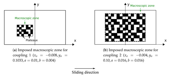
Figure 17.
Microscopic scale scheme (plateaus in black).
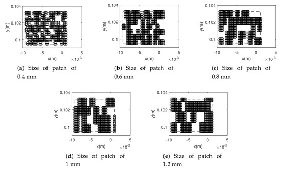
Figure 18.
Examples of distribution of plateaus at an imposed macroscopic contact zone for coupling 2.
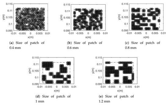
Figure 19.
Examples of distribution of plateaus at an imposed macroscopic contact zone for coupling 1.
Overall, for the imposed macroscopic contact zone for unstable frequency at 2100 Hz, 1069 distributions of plateaus are found unstable. This sum represents 76.3% of the number of random distributions. The divergence rate and corresponding unstable frequency are shown in Figure 20. These unstable frequencies do not change so much (around 2100 Hz) whereas the divergence rates vary strongly from 0.44 to 1.9%. It can be concluded that distributions of plateaus can suppress instability or modify the intensity of unstable mode at about 2100 Hz. However, they do not change unstable frequency. Similarly, for the imposed macroscopic contact zone for unstable frequency at 3500 Hz, 65.1% of the number of random distributions is found unstable. The divergence rate and corresponding unstable frequency are shown in Figure 21. These unstable frequencies do not change so much (about 3500 Hz) whereas the divergence rates vary strongly from 0.2 to 1.6%. The distributions of plateaus can suppress instability or modify the intensity of unstable mode at about 3500 Hz.
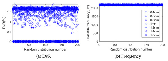
Figure 20.
Results for coupling 2 at mesoscopic scale.
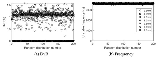
Figure 21.
Results for coupling 1 at mesoscopic scale.
Figure 22 shows the percentage of unstable cases as a function of the patch size. The number of unstable cases decreases as the patch size increases for the 2 couplings. It also appears that this decrease appears for a patch size above a significant value (0.4 mm and 0.5 mm respectively for coupling 1 and 2). Below these values, contact zones appear as macroscopic flat and continuous ones. However, above these sizes, the ratio of unstable sampling decreases significantly, which can be interpreted as a dispersive squeal occurrence, considering that plateaus with size and localization variations differ according to tribological mechanism.
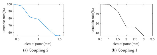
Figure 22.
Effect of the patch size on mode-coupling instabilities.
Figure 23, Figure 24, Figure 25 and Figure 26 show some distributions of plateaus which trigger or suppress unstable modes. They can reduce significantly the corresponding macroscopic area and therefore make the system stable (Figure 24d,f). However, in some cases, even if this macroscopic area does not change much, the system can still become stable.
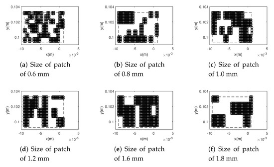
Figure 23.
Some distributions of plateaus which trigger coupling 2.
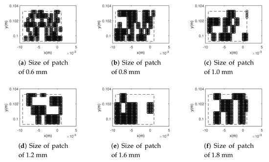
Figure 24.
Some distributions of plateaus which vanish coupling 2.
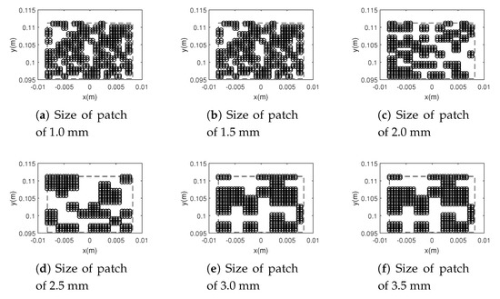
Figure 25.
Some distributions of plateaus which trigger coupling 1.
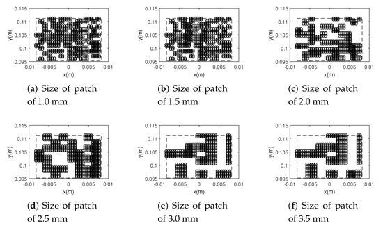
Figure 26.
Some distributions of plateaus which vanish coupling 1.
In this section, it is found that instabilities of the system can change as a function of the distribution of plateaus at a mesoscopic scale. Instabilities can be suppressed or be very sensible as a function of the random distribution of plateaus. For these simulations, no change of unstable frequency is found at this scale. In fact, transient process of tribolayer evolution and macroscopic contact variation has to be considered as in [44] exhibiting the effect of thermal dilatation and wear on instability.
4. Conclusions
The aim of this paper was to consider the effect of contact localization on squeal, on a pin-on-disc system close to braking application. As in reality multiscale localizations appear and could change in time, superposition of localization scales have been considered. By using a full finite element method and considering mode-coupling as instability mechanism, it is firstly found that numerical simulations can underestimate unstable frequency if they do not take into account “real” contact zones. Secondly, there is a strong dependency between the squeal occurrence and contact geometry at macroscopic and mesoscopic scales. These scales concern the global contact areas and the tribological mechanisms (topography and third body nature). The unstable dynamical behavior (unstable frequencies) depends on the localization and the size of macroscopic contact zones. At mesoscopic scale, it is the instability occurrence which is sensible to the distribution of plateaus as clearly observed in this study. However, no change of unstable frequency is found at this scale.
With these results it is also shown that it is crucial to consider the evolution of contact areas, at the macroscopic scale and at the mesoscopic scale above dimensions of several hundreds of microns. Below these values, influence on instabilities vanishes. Evolution has to consider thermo-mechanical effects and tribologcal mechanisms related to wear and third body rheology.
As a way of using these results practically, controlling macroscopic localizations could be the most suitable key to reduce friction-induced vibrations, but the thermomechanical evolution has to be considered. The mesoscopic scale is probably more difficult to monitor but could be a precious key to limit squeal occurrences.
The numerical analyses showed significant influence of contact localizations variation over the appearance of unstable modes. In future studies, heterogeneities of material at contact zone needs to be carried out in order to investigate more exclusively influence of contact geometry on the squeal occurrence. Evolution process of thermo-mechanical and tribological effects have also to be introduced.
Author Contributions
Conceptualization, V.-V.L. and J.-F.B.; methodology, V.-V.L.; software, V.-V.L.; validation, V.-V.L., J.-F.B. and P.D.; investigation, V.-V.L., J.-F.B. and P.D.; data curation, J.-F.B. and I.P.; writing—original draft preparation, V.-V.L.; writing—review and editing, V.-V.L., J.-F.B. and P.D. All authors have read and agreed to the published version of the manuscript.
Funding
This research received no external funding.
Acknowledgments
The present research work has been supported by the ELSAT2020 project co-financed by the European Union with the European Regional Development Fund, the French State and the Hauts de France Region Council. The authors gratefully acknowledge the support of these institutions.
Conflicts of Interest
The authors declare no conflict of interest.
References
- Akay, A. Acoustics of friction. J. Acoust. Soc. Am. 2002, 111, 1525–1548. [Google Scholar] [CrossRef]
- Junior, M.T.; Gerges, S.N.; Jordan, R. Analysis of brake squeal noise using the finite element method: A parametric study. Appl. Acoust. 2008, 69, 147–162. [Google Scholar] [CrossRef]
- Eriksson, M.; Lundqvist, A.; Jacobson, S. A study of the influence of humidity on the friction and squeal generation of automotive brake pads. Proc. Inst. Mech. Eng. Part D J. Automob. Eng. 2001, 215, 329–342. [Google Scholar] [CrossRef]
- Ibrahim, R. Friction-Induced Noise and Related Problems in Automotive Brakes. In Research Developments in Sound and Vibration; Transworld Research Network: Kerala, India, 2002. [Google Scholar]
- Desplanques, Y.; Degallaix, G. Interactions between third-body flows and localisation phenomena during railway high-energy stop braking. Sae Int. J. Passeng. Cars-Mech. Syst. 2008, 1, 1267–1275. [Google Scholar] [CrossRef]
- Singla, N.; Brunel, J.-F.; Mège-Revil, A.; Kasem, H.; Desplanques, Y. Experiment to investigate the relationship between the third-body layer and the occurrence of squeals in dry sliding contact. Tribol. Lett. 2020, 68, 4. [Google Scholar] [CrossRef]
- Österle, W.; Dörfel, I.; Prietzel, C.; Rooch, H.; Cristol-Bulthé, A.-L.; Degallaix, G.; Desplanques, Y. A comprehensive microscopic study of third body formation at the interface between a brake pad and brake disc during the final stage of a pin-on-disc test. Wear 2009, 267, 781–788. [Google Scholar] [CrossRef]
- Kasem, H.; Bonnamy, S.; Rousseau, B.; Estrade-Szwarckopf, H.; Berthier, Y.; Jacquemard, P. Interdependence between wear process, size of detached particles and co2 production during carbon/carbon composite friction. Wear 2007, 263, 1220–1229. [Google Scholar] [CrossRef]
- Eriksson, M.; Jacobson, S. Friction behaviour and squeal generation of disc brakes at low speeds. Proc. Inst. Mech. Eng. Part D J. Automob. Eng. 2001, 215, 1245–1256. [Google Scholar] [CrossRef]
- Sherif, H.A. Effect of contact stiffness on the establishment of self-excited vibrations. Wear 1991, 141, 227–234. [Google Scholar] [CrossRef]
- Sherif, H.A.; Kossa, S. Relationship between normal and tangential contact stiffness of nominally flat surfaces. Wear 1991, 151, 49–62. [Google Scholar] [CrossRef]
- Sherif, H. Investigation on effect of surface topography of pad/disc assembly on squeal generation. Wear 2004, 257, 687–695. [Google Scholar] [CrossRef]
- Lee, S.; Shin, M.; Jang, H. Friction-induced intermittent motion affected by surface roughness of brake friction materials. Wear 2013, 308, 29–34. [Google Scholar] [CrossRef]
- Magnier, V.; Brunel, J.-F.; Dufrénoy, P. Impact of contact stiffness heterogeneities on friction-induced vibration. Int. J. Solids Struct. 2014, 51, 1662–1669. [Google Scholar] [CrossRef]
- Eriksson, M.; Bergman, F.; Jacobson, S. Surface characterisation of brake pads after running under silent and squealing conditions. Wear 1999, 232, 163–167. [Google Scholar] [CrossRef]
- Eriksson, M.; Bergman, F.; Jacobson, S. On the nature of tribological contact in automotive brakes. Wear 2002, 252, 26–36. [Google Scholar] [CrossRef]
- Yoon, S.; Shin, M.; Lee, W.; Jang, H. Effect of surface contact conditions on the stick-slip behavior of brake friction material. Wear 2012, 294, 305–312. [Google Scholar] [CrossRef]
- Lee, S.; Jang, H. Effect of plateau distribution on friction instability of brake friction materials. Wear 2018, 400, 1–9. [Google Scholar] [CrossRef]
- Kim, J.W.; Joo, B.S.; Jang, H. The effect of contact area on velocity weakening of the friction coefficient and friction instability: A case study on brake friction materials. Tribol. Int. 2019, 135, 38–45. [Google Scholar] [CrossRef]
- Bergman, F.; Eriksson, M.; Jacobson, S. The effect of reduced contact area on the occurrence of disc brake squeals for an automotive brake pad. Proc. Inst. Mech. Eng. Part D J. Automob. Eng. 2000, 214, 561–568. [Google Scholar] [CrossRef]
- Duboc, M.; Magnier, V.; Brunel, J.-F.; Dufrénoy, P. Experimental set-up and the associated model for squeal analysis. Mech. Ind. 2020, 21, 204. [Google Scholar] [CrossRef]
- AbuBakar, A.R.; Ouyang, H. Wear prediction of friction material and brake squeal using the finite element method. Wear 2008, 264, 1069–1076. [Google Scholar] [CrossRef]
- Ramasami, D.N. Influence of Friction Material & Test Sequence on Disc Brake Squeal. Ph.D. Thesis, Lille 1, Villeneuve-d’Ascq, France, 2014. [Google Scholar]
- Gao, C.; Kuhlmann-Wilsdorf, D.; Makel, D.D. Fundamentals of stick-slip. Wear 1993, 162, 1139–1149. [Google Scholar] [CrossRef]
- Gao, C.; Kuhlmann-Wilsdorf, D.; Makel, D.D. The dynamic analysis of stick-slip motion. Wear 1994, 173, 1–12. [Google Scholar] [CrossRef]
- Ibrahim, R. Friction-induced vibration, chatter, squeal, and chaos—Part i: Mechanics of contact and friction. Appl. Mech. Rev. 1994, 47, 209–226. [Google Scholar] [CrossRef]
- Ibrahim, R. Friction-induced vibration, chatter, squeal, and chaos—Part ii: Dynamics and modeling. Appl. Mech. Rev. 1994, 47, 227–253. [Google Scholar] [CrossRef]
- Jarvis, R.; Mills, B. Vibrations induced by dry friction. Proc. Inst. Mech. Eng. 1963, 178, 847–857. [Google Scholar] [CrossRef]
- Spurr, R.T. A theory of brake squeal. Proc. Inst. Mech. Eng. Automob. Div. 1961, 15, 33–52. [Google Scholar] [CrossRef]
- Chambrette, P.; Jezequel, L. Stability of a beam rubbed against a rotating disc. Eur. J. Mech. A Solids 1992, 11, 107–138. [Google Scholar]
- Hoffmann, N.; Fischer, M.; Allgaier, R.; Gaul, L. A minimal model for studying properties of the mode-coupling type instability in friction induced oscillations. Mech. Res. Commun. 2002, 29, 197–205. [Google Scholar] [CrossRef]
- Sinou, J.-J. Transient non-linear dynamic analysis of automotive disc brake squeal-on the need to consider both stability and non-linear analysis. Mech. Res. Commun. 2010, 37, 96–105. [Google Scholar] [CrossRef]
- Lorang, X.; Foy-Margiocchi, F.; Nguyen, Q.; Gautier, P. {TGV} disc brake squeal. J. Sound Vib. 2006, 293, 735–746. [Google Scholar] [CrossRef]
- Massi, F.; Baillet, L.; Giannini, O.; Sestieri, A. Brake squeal: Linear and nonlinear numerical approaches. Mech. Syst. Signal Process. 2007, 21, 2374–2393. [Google Scholar] [CrossRef]
- Tison, T.; Heussaff, A.; Massa, F.; Turpin, I.; Nunes, R. Improvement in the predictivity of squeal simulations: Uncertainty and robustness. J. Sound Vib. 2014, 333, 3394–3412. [Google Scholar] [CrossRef]
- Sinou, J.-J.; Jézéquel, L. Mode coupling instability in friction-induced vibrations and its dependency on system parameters including damping. Eur. J. Mech. A Solids 2007, 26, 106–122. [Google Scholar] [CrossRef]
- Denimal, E.; Sinou, J.-J.; Nacivet, S. Influence of structural modifications of automotive brake systems for squeal events with kriging meta-modelling method. J. Sound Vib. 2019, 463, 114938. [Google Scholar] [CrossRef]
- Denimal, E.; Sinou, J.-J.; Nacivet, S.; Nechak, L. Squeal analysis based on the effect and determination of the most influential contacts between the different components of an automotive brake system. Int. J. Mech. Sci. 2019, 151, 192–213. [Google Scholar] [CrossRef]
- Loyer, A.; Sinou, J.-J.; Chiello, O.; Lorang, X. Study of nonlinear behaviors and modal reductions for friction destabilized systems. Application to an elastic layer. J. Sound Vib. 2012, 331, 1011–1041. [Google Scholar] [CrossRef][Green Version]
- Brizard, D.; Chiello, O.; Sinou, J.-J.; Lorang, X. Performances of some reduced bases for the stability analysis of a disc/pads system in sliding contact. J. Sound Vib. 2011, 330, 703–720. [Google Scholar] [CrossRef]
- Sorensen, D.C. Implicit application of polynomial filters in ak-step arnoldi method. Siam J. Matrix Anal. Appl. 1992, 13, 357–385. [Google Scholar] [CrossRef]
- Bobillot, A. Méthodes de Réduction Pour le Recalage Application au cas D’ariane 5. Ph.D. Thesis, Ecole Centrale Paris, Châtenay-Malabry, France, 2002. [Google Scholar]
- Quéméner, O.; Battaglia, J.-L.; Neveu, A. Résolution d’un problème inverse par utilisation d’un modèle réduit modal. application au frottement d’un pion sur un disque en rotation. Int. J. Therm. Sci. 2003, 42, 361–378. [Google Scholar] [CrossRef]
- Waddad, Y.; Magnier, V.; Dufrénoy, P.; Saxcé, G.D. Multiscale thermomechanical modeling of frictional contact problems considering wear–application to a pin-on-disc system. Wear 2019, 426, 1399–1409. [Google Scholar] [CrossRef]


© 2020 by the authors. Licensee MDPI, Basel, Switzerland. This article is an open access article distributed under the terms and conditions of the Creative Commons Attribution (CC BY) license (http://creativecommons.org/licenses/by/4.0/).