Close-to-Application Test Methodology Validated by a Baseline Study for Novel Bearing Developments in Aircraft Turbines


Abstract
:
1. Introduction
2. Methodology
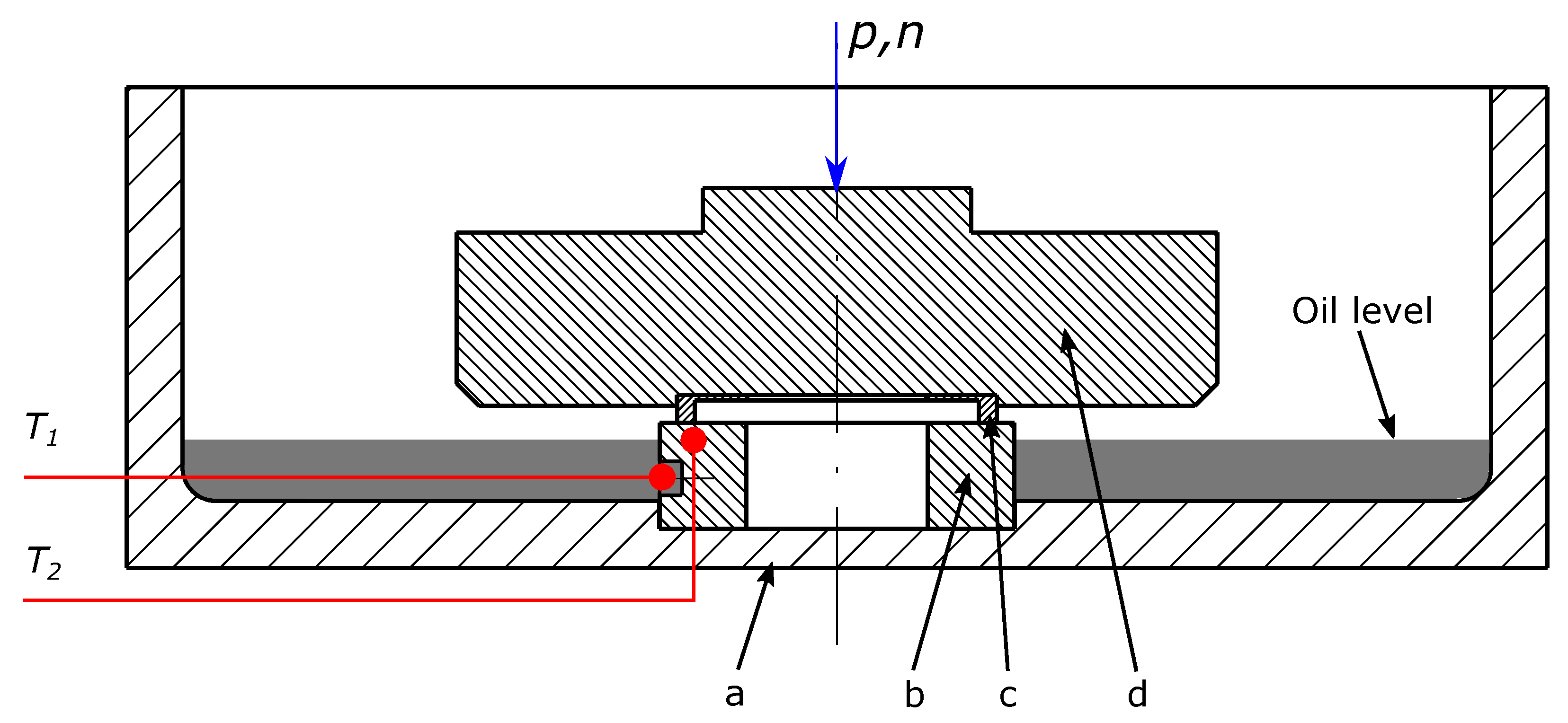
2.1. Test Rigs
Bearing Segment Tester
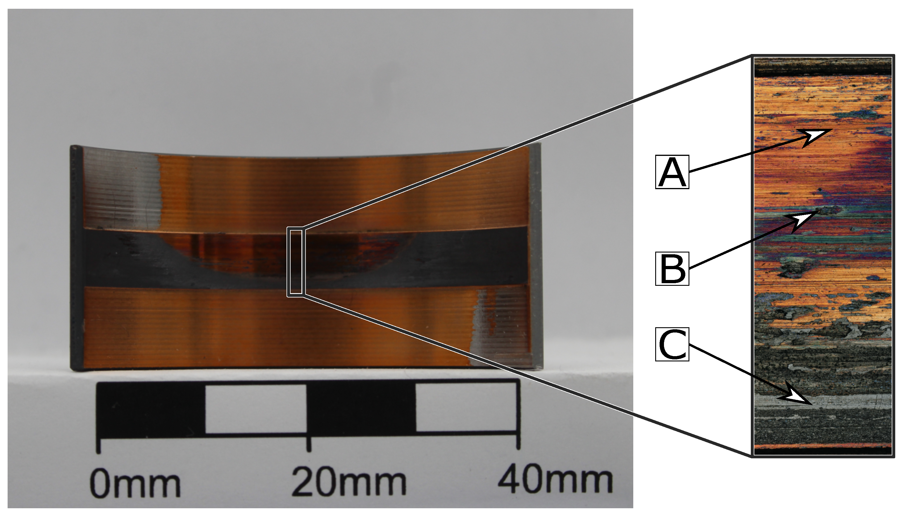
2.2. Ex-Situ Wear Measurement
Ring on Disc Set Up
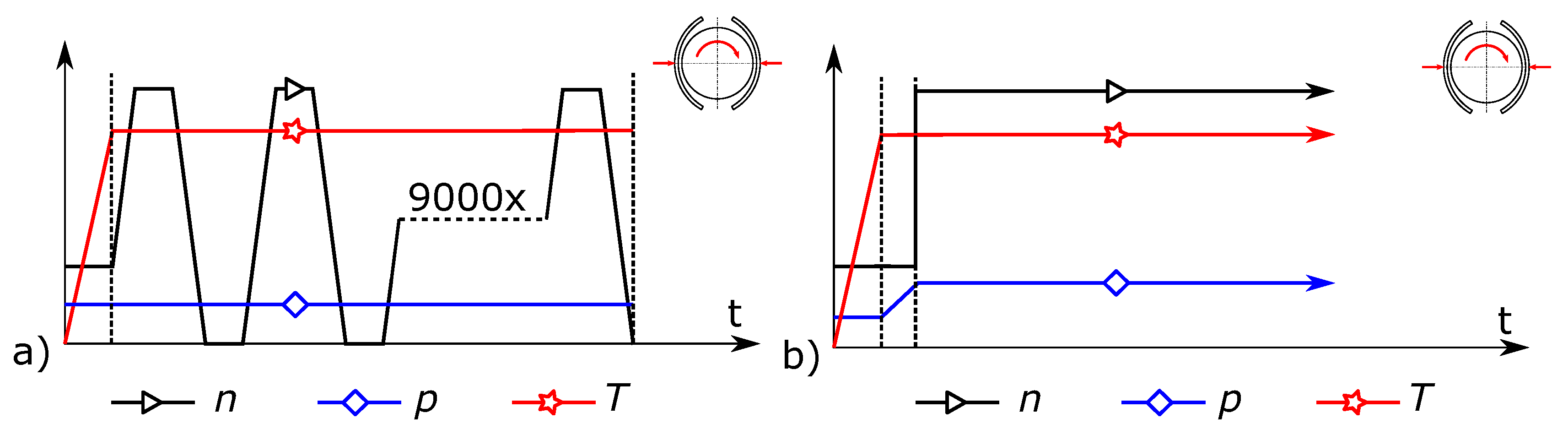
2.3. Test Programs
2.4. Materials
3. Results
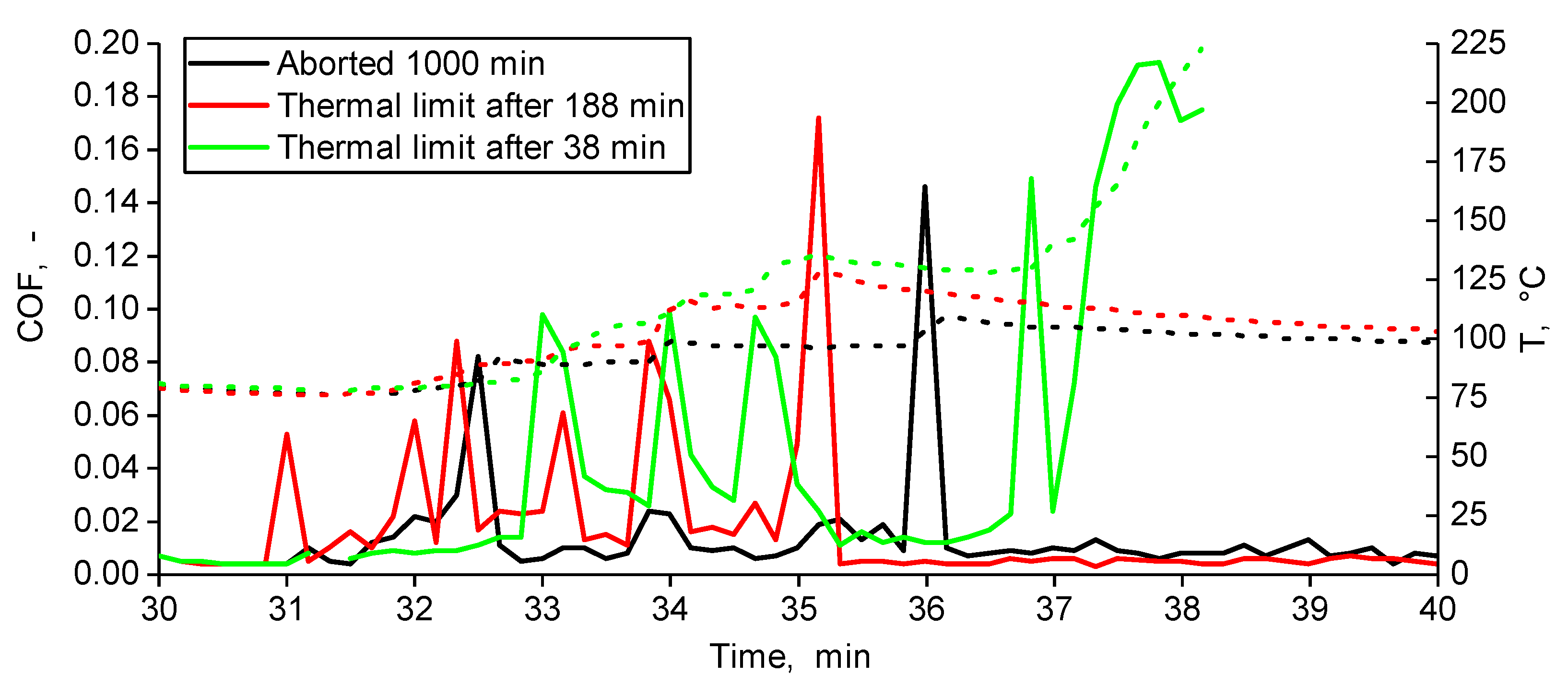
3.1. Seizure Tests
3.1.1. Electroplated SnCuSbNi
3.1.2. Uncoated Lining Material
3.2. Dry-Run-Tests
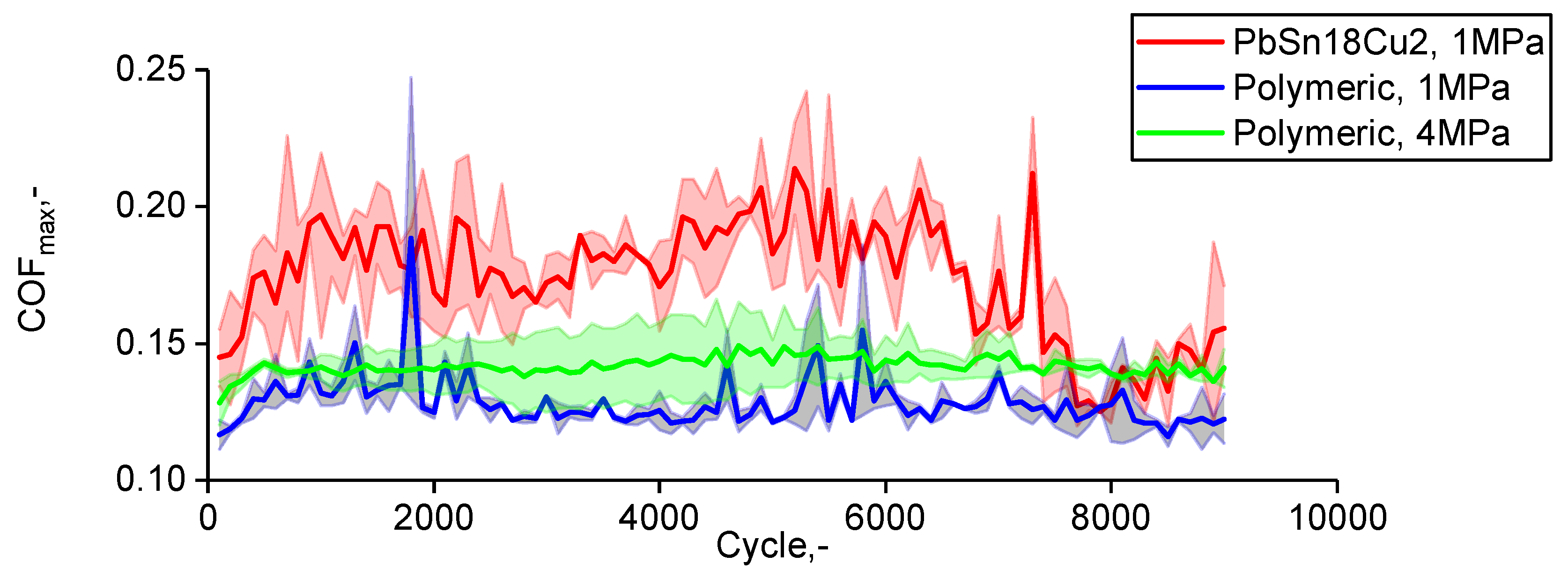
3.3. Start-Stop-Tests
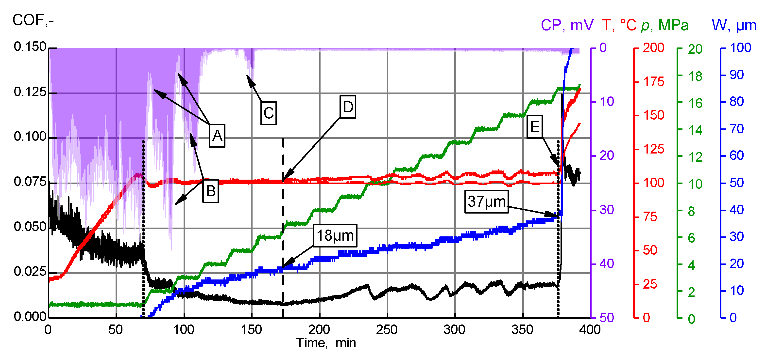
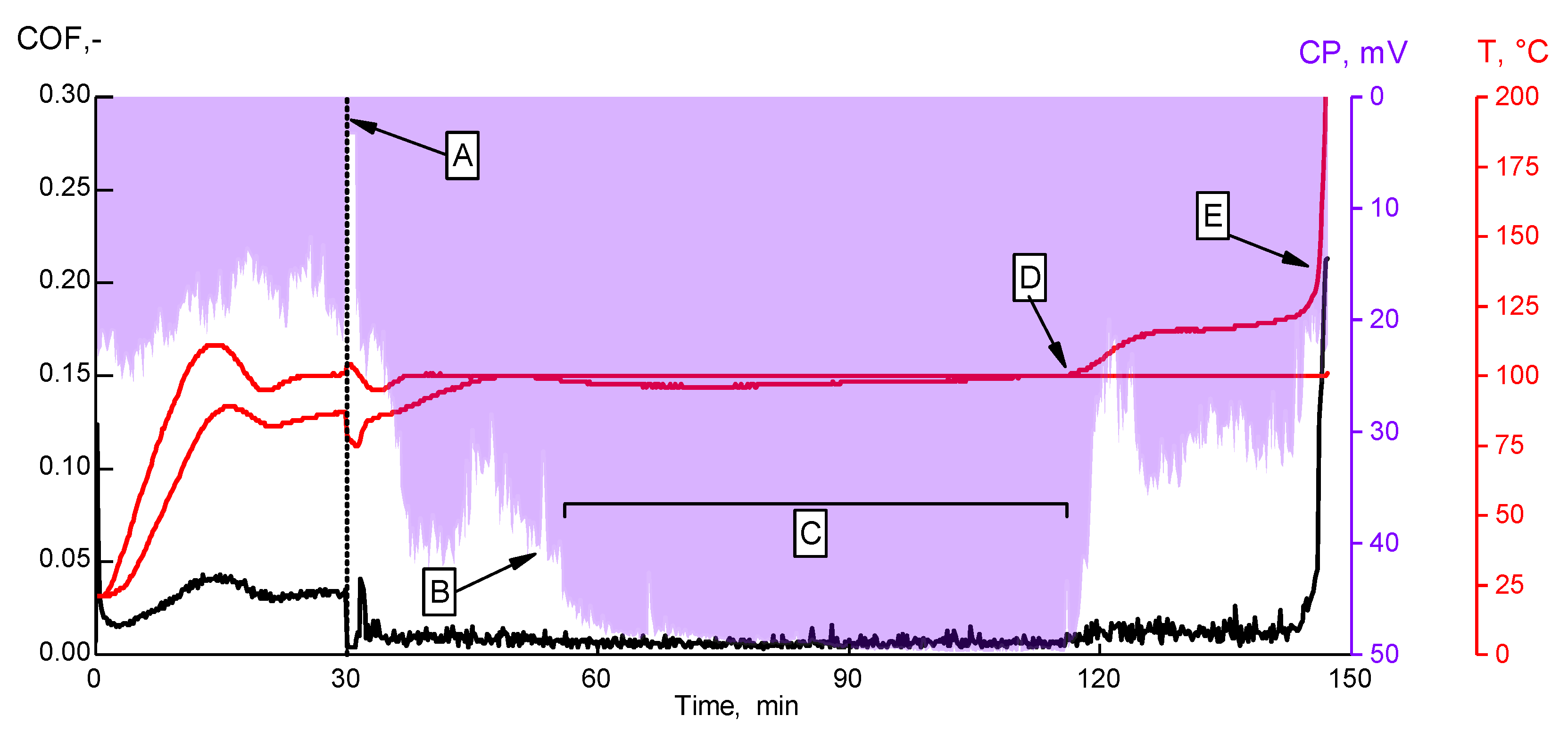
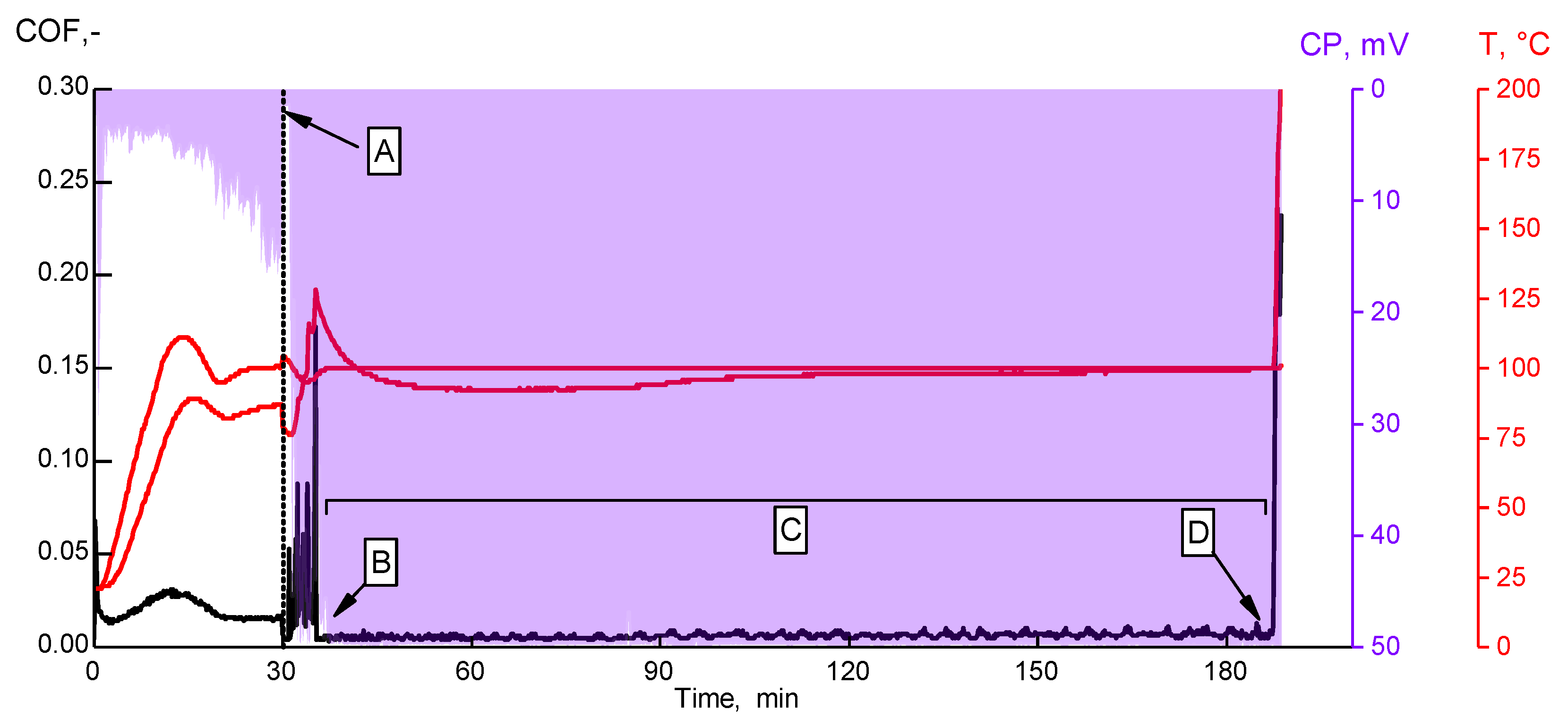
3.4. Oil-Starvation-Tests
3.4.1. Polymeric Coating
3.4.2. Electroplated Coating
4. Conclusions
Author Contributions
Funding
Conflicts of Interest
Abbreviations
| VHBR | Very high bypass ratio |
| JBGR | Journal bearing |
| BST | Bearing-segment tester |
| ROD | Ring-on-disc |
| SST | Start-Stop-test |
| DRT | Dry-Run-test |
| ST | Seizure-test |
| OST | Oil-starvation-test |
| ZDDP | Zincdialkyldithiophosphate |
| TCP | Tricresylphosphate |
References
- Dik, A.; Bitén, N.; Zaccaria, V.; Aslanidou, I.; Kyprianidis, K.G. Conceptual Design of a 3-Shaft Turbofan Engine with Reduced Fuel Consumption for 2025. Energy Procedia 2017, 142, 1728–1735. [Google Scholar] [CrossRef]
- Balli, O. Exergy modeling for evaluating sustainability level of a high by-pass turbofan engine used on commercial aircrafts. Appl. Therm. Eng. 2017, 123, 138–155. [Google Scholar] [CrossRef]
- Bräunling, W.J. Flugzeugtriebwerke: Grundlagen, Aero-Thermodynamik, Ideale und Reale Kreisprozesse, Thermische Turbomaschinen, Komponenten, Emissionen und Systeme; Springer: Berlin/Heidelberg, Germany, 2009. [Google Scholar] [CrossRef]
- Menezes, P.L.; Nosonovsky, M.; Ingole, S.P.; Kailas, S.V.; Lovell, M.R. Tribology for Scientists and Engineers: From Basics to Advanced Concepts; Springer: New York, NY, USA, 2013. [Google Scholar] [CrossRef]
- Affenzeller, J.; Gläser, H. Lagerung und Schmierung von Verbrennungsmotoren; Springer: Heidelberg, Germany, 1996. [Google Scholar]
- Summer, F.; Grün, F.; Offenbecher, M.; Taylor, S. Challenges of friction reduction of engine plain bearings–Tackling the problem with novel bearing materials. Tribol. Int. 2018, 131, 238–250. [Google Scholar] [CrossRef]
- Summer, F.; Grün, F.; Offenbecher, M.; Taylor, S.; Lainé, E. Tribology of journal bearings: Start stop operation as life-time factor. Tribol. und Schmier. 2017, 64, 44–54. [Google Scholar]
- Grün, F.; Gódor, I.; Gärtner, W.; Eichlseder, W. Tribological performance of thin overlays for journal bearings. Tribol. Int. 2011, 44, 1271–1280. [Google Scholar] [CrossRef]
- Gebretsadik, D.W.; Hardell, J.; Prakash, B. Seizure behavior of some selected Pb-free engine bearing materials under lubricated condition. Tribol. Int. 2017, 111, 265–275. [Google Scholar] [CrossRef]
- Gebretsadik, D.W.; Hardell, J.; Prakash, B. Tribological performance of tin-based overlay plated engine bearing materials. Tribol. Int. 2015, 92, 281–289. [Google Scholar] [CrossRef]
- Bergseth, E.; Henriksson, M.; Dizdar, S.; Sellgren, U. Effects of thrust washer bearing surface characteristics on planetary gear train wear. Wear 2019, 432–433, 202933. [Google Scholar] [CrossRef]
- Adam, A.; Prefot, M.; Wilhelm, M. Crankshaft bearings for engines with start-stop systems. MTZ Worldw. 2010, 71, 22–25. [Google Scholar] [CrossRef]
- Schouwenaars, R.; Jacobo, V.H.; Ortiz, A. Microstructural aspects of wear in soft tribological alloys. Wear 2007, 263, 727–735. [Google Scholar] [CrossRef]


| Specimen Geometry | Lining Material | Coating | Thickness, μm | Test Program | Performed Tests |
|---|---|---|---|---|---|
| ROD | CuPb22Sn2 | Polymer | 17 | DRT | 5 |
| ROD | CuPb22Sn2 | SnCuSbNi | 16 | ST | 7 |
| ROD | CuPb22Sn2 | uncoated | n.a | ST | 5 |
| BST | CuPb22Sn2 | PbSn18Cu2 | 16 | OST and SST | 4 and 5 |
| BST | CuPb22Sn2 | Polymer | 16 | OST and SST | 5 and 7 |
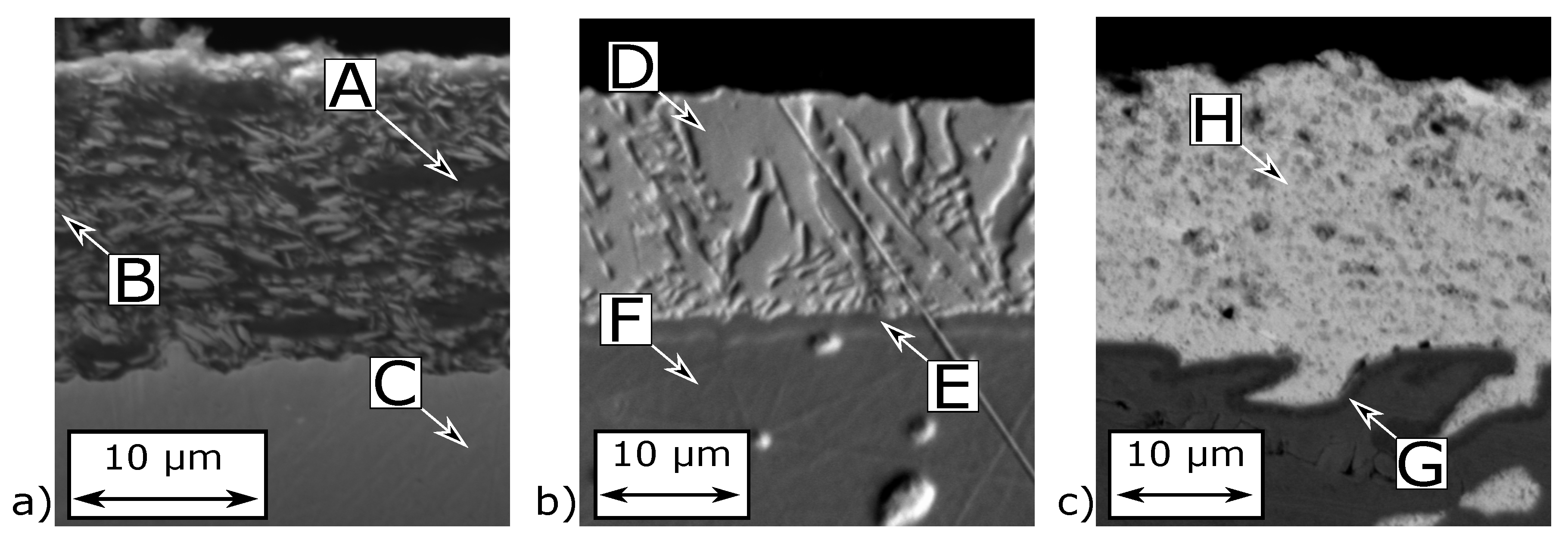
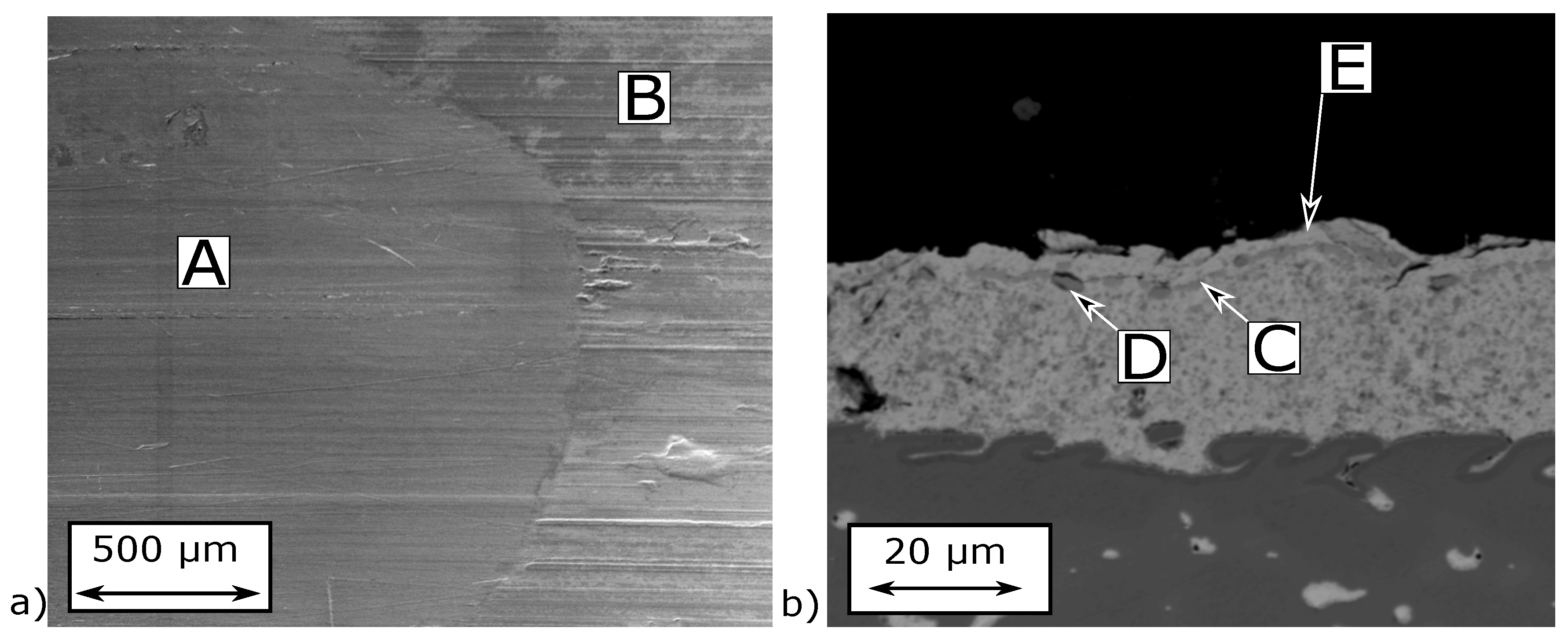
| Position | C | O | S | Ti | Cu | Mo | Sn | Ni | Pb |
|---|---|---|---|---|---|---|---|---|---|
| A | 53.95 | 7.90 | 4.15 | 26.03 | - | 7.97 | - | - | - |
| B | 39.55 | 7.90 | 19.88 | 32.67 | - | - | - | - | - |
| C | 1.12 | - | - | - | 93.96 | - | 4.92 | - | - |
| D | - | - | - | - | - | - | 100 | - | - |
| E | 4.4 | - | - | - | - | - | - | 95.6 | - |
| F | 2.01 | - | - | - | 94.79 | - | 3.20 | - | - |
| G | 2.97 | - | - | - | 10.32 | - | 0.81 | 85.90 | - |
| H | 2.84 | 6.03 | - | - | 3.56 | - | 14.84 | - | 72.73 |
© 2020 by the authors. Licensee MDPI, Basel, Switzerland. This article is an open access article distributed under the terms and conditions of the Creative Commons Attribution (CC BY) license (http://creativecommons.org/licenses/by/4.0/).
Share and Cite
Renhart, P.; Summer, F.; Grün, F.; Eder, A. Close-to-Application Test Methodology Validated by a Baseline Study for Novel Bearing Developments in Aircraft Turbines. Lubricants 2020, 8, 7. https://doi.org/10.3390/lubricants8010007
Renhart P, Summer F, Grün F, Eder A. Close-to-Application Test Methodology Validated by a Baseline Study for Novel Bearing Developments in Aircraft Turbines. Lubricants. 2020; 8(1):7. https://doi.org/10.3390/lubricants8010007
Chicago/Turabian StyleRenhart, Philipp, Florian Summer, Florian Grün, and Andreas Eder. 2020. "Close-to-Application Test Methodology Validated by a Baseline Study for Novel Bearing Developments in Aircraft Turbines" Lubricants 8, no. 1: 7. https://doi.org/10.3390/lubricants8010007
APA StyleRenhart, P., Summer, F., Grün, F., & Eder, A. (2020). Close-to-Application Test Methodology Validated by a Baseline Study for Novel Bearing Developments in Aircraft Turbines. Lubricants, 8(1), 7. https://doi.org/10.3390/lubricants8010007