Article

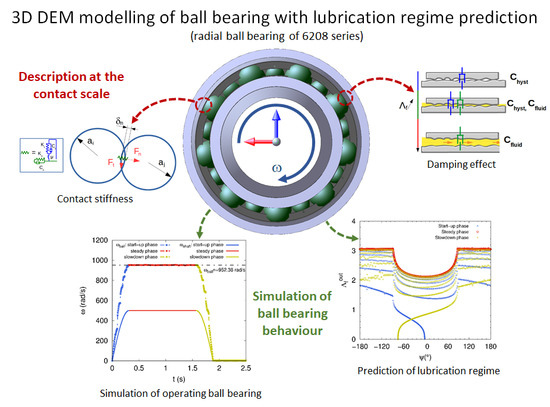
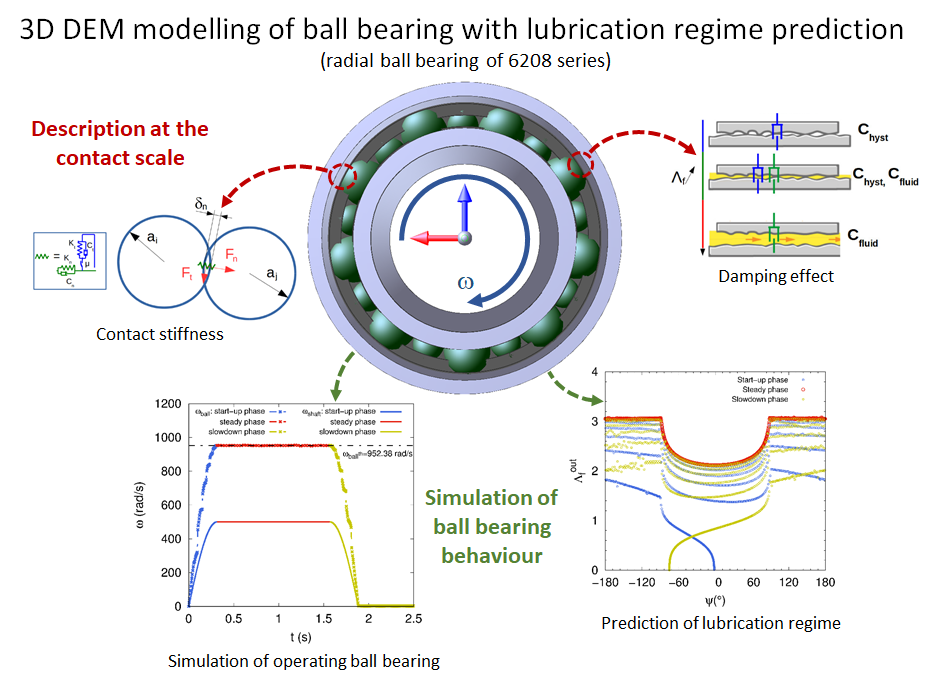
Three-Dimensional DEM Modelling of Ball Bearing with Lubrication Regime Prediction

Campus Universitaire—LTI-EA3899, 48 rue d’Ostende, 02315 Saint-Quentin, France
*
Author to whom correspondence should be addressed.
Lubricants 2018, 6(2), 46; https://doi.org/10.3390/lubricants6020046
Submission received: 28 February 2018 / Revised: 2 May 2018 / Accepted: 3 May 2018 / Published: 8 May 2018
(This article belongs to the Special Issue Computer Simulation in Tribology and Friction)

Abstract

:
This paper deals with an efficient 3D modelling of a radial ball bearing to predict the operating lubrication regime under mechanical loading and mounting conditions by using the Discrete Element Method (DEM). Due to the relevance of such an approach, especially for multicontact systems, the lubrication regime associated with specific operating conditions can be predicted accurately. By means of an elastohydrodynamic lubrication formulation depending on parameters related to the size of contact area, mechanical properties of materials, roughness and fluid viscosity, the lubricant film thickness is predicted and used to take into consideration the fluid film damping effect and friction coefficient variation. The lubrication regime can be identified according to Stribeck curve with the assumption of a piezo-viscous-elastic behaviour of the lubricant. The numerical simulations performed with MULTICOR-3D software on an operating ball bearing shown that the lubrication regime at the rolling element-raceway contact can be easily monitored and quantitatively identified. To assess the efficiency of the discrete modelling, a parametric study is carried out in order to exhibit how the operating conditions affect the lubrication regimes and the fluid film spread in the loaded zone. The adequacy between the choice of lubricant and the bearing tribofinition is sought to optimize the component lifetime.

Graphical Abstract

1. Introduction

Rolling bearings are widely used components in both industrial and domestic rotating machinery. There is a large number of bearings for all possible applications, among them radial and oblique ball bearings, roller bearings, ball and roller thrust bearings, and many others. However, statistical studies show that in industrial applications more than 50% of malfunctions of rotating machineries are caused by shaft misalignment [1]. Therefore this recurrent defect unfortunately plays a central role in the degradation of bearings and malfunctions in rotating machinery. In the modern area of the smart factory (Factory 4.0) [2,3], when attempts are being made to obtain relevant real time information on rotating machines, using connected devices called Internet of Things (IoT) is sought, and also with increasing demands on industry to reduce energy consumption and gas emissions, the effort to increase the efficiency of machine components is no doubt more intense than ever. In order to ensure the industrial systems’ availability and the safety of goods and persons, the monitoring and diagnosis of bearing malfunctions have to be considered with prime importance, thereby ensuring good maintenance. Moreover, the challenges in terms of productivity and economic cost are obviously non-negligible. Therefore, defect tracking of rolling bearings components has led to extensive research over many years. Several experimental methods and various types of signal analysis have been developed for the detection and diagnosis of rolling bearing defects, such as vibration measurements [4], acoustic emission [5], defect signatures in the stator current of motors [6], thermal and lubrication analysis [7].
However, another very important and key aspect on which the performance of rolling bearings depends concerns lubrication. Because of its preponderant role, lubrication in fact plays a vital role in most machine components in ensuring that they work properly, are efficient and have a satisfactory service life. With clearance and alignment correction, lubrication is the main maintenance operation, without dismounting. Hamrock and Dowson [8,9] performed pioneering studies on lubricated contacts. The authors implemented a series of EHL (Elasto-Hydrodynamic Lubrication) numerical analysis for elliptical contacts and considered a wide range of load, velocity and material properties variations. Several curve-fit formulas derived form their numerical results characterize different fluid film thickness regimes, and which are still the most popular and frequently used today. More recently, Masjedi and Khonsari [10] have improved the EHL model, initially introduced by Hamrock and Dowson, proposing formulas to take into account the effect of surface roughness to predict central fluid film thickness, minimum film thickness and the asperity load ratio. It is, therefore, strongly advised that mechanical systems with non-conformal contacts should be mounted with sufficient clearance because the lubricant film should be thick enough as far as possible to avoid contact between the mating surfaces. This ensures the limitation of wear mechanisms that could occur at the contact interface between two surfaces. In this case, the friction coefficient is rather low. On the other hand, when the rotating machines are subjected to more severe operating conditions, typically under very high loads or at low speeds, then the load carried by the contacting asperities should be taken into consideration. According to Stribeck analysis [11], the relation between the friction coefficient μ and the fluid parameter Λ f (Sommerfeld number or Hersey number) is often used as an indicator to distinguish between the different lubrication regimes. Moreover, the increasing developments related to tribological studies have considerably enhanced our understanding of the mechanisms of lubrication that take place in highly loaded non-conformal contacts, in the case of rolling bearings, gears and cams [12,13], as well as for the identification of the fluid film thickness [14,15] and the characterization of the friction behaviour [16,17].
Wear and fatigue damage behaviour in bearings is hard to describe theoretically and numerically. Indeed, both wear and fatigue mechanisms are quite complex and essentially dependent on operating conditions, lubricant quality associated with a good mounting and a suitable bearing design. To overcome these limitations, a numerical twin of bearings, based on DEM using MULTICOR-2D software, has been developed to enable users to access outputs relative to damage initiation and to improve coupling models for monitoring [18,19]. Moreover, since 2008, several studies carried out in our research laboratory (LTI EA-3899) have clearly established the relevance of electrical measurements located on dynamic interfaces and have generated a promising approach for the monitoring of bearings and preventing material wear in wind plant applications [20,21]. By using a refined electrical resistivity circuit, some recent work has also shown the relevance of electrical measurements in characterizing the lubrication regime at the contact interface [22] and investigating the influence of the spin coating process on the oil film lifetime [23]. Combining an improved electrical signal, where the lubricated contact and friction play a key role, with the existing monitoring methods [24] should lead to a high-performance rotating machine tracking tool. From an industrial point of view, obtaining real-time information including a qualitative definition of the rolling contact quality based on electrical measurements would allow the lifetime of rotating machines to be optimized. From a numerical point of view, generating mechanical responses of a bearing using DEM allows us to go further in the knowledge of monitoring signals, instead of investigating mechanisms responsible for wear. For example, wear debris can contaminate lubricated bearings and impede contacts resulting in lubrication failure and subsequent overheating. Our recent article [18] exhibits the potential of DEM simulations to investigate fatigue mechanism by accessing stress in rings.
A focus on the potential offered by the DEM for simulating the dynamic behavior of bearings with a 2D description is well described in our previous work [25,26], assuming a simple contact model without tribology enrichments. In this paper, a 3D DEM model is enriched with the phenomenological contribution of lubrication, in order to develop a monitoring tool based on an electrical measurement [21]. In this sense, the lubricant consideration must remain sufficiently adapted to the scale of the apparent contact, where the competition between the metal-metal contact with asperities (resistive) and the contact through the fluid (capacitive) plays an essential role in electromechanical coupling. To achieve this proposal, from a mechanical standpoint, a three dimensional dynamic model for ball bearings based on MULTICOR-3D software is developed. The aim is to create a lubrication model by using a discrete formulation. The proposed model implements a major part of the functionalities according to the state of the art, such as the slice model, the mutual influences of neighbouring elements with clearance, elastic contact models, lubricant film estimation, damping forces, centrifugal forces, etc. In particular, the DEM model with strong assumptions introduces the basics of lubrication regimes in order to maintain efficiency in solving, as long as it could be simulated in an acceptable computational time. Technically, the smooth DEM methodology selects stiffnesses and damping coefficients (critical damping) and a constant coefficient of friction for simulations related to granular media [27,28]. Following this tutorial dedicated to bearing application, stiffnesses are calibrated for bearings and typical load-deflections relationship are validated [20,29]. Dampings [30] and friction [31] acquire a more physical meaning when a lubricant is considered [8,32,33]. The friction coefficients, usually considered as an input parameter are now implicitly set at each contact. When the roughness is known, the parameter that indicates a good lubrication regime is the minimum fluid film thickness. This parameter must has values that do not fall below the roughness because a film thickness that is too small leads to risks of metal-metal contact, causing irreversible damage. Future numerical developments and experimental investigations will attempt to define electromechanical coupling models implemented in DEM simulations, based on the capacitive and resistive behaviour of lubricating contacts. When lubrication is introduced under a restrictive assumption on the fluid rheology, the resulting damping forces should be included.
The paper is divided into four sections, including two sections dedicated to the introduction and conclusion, respectively. The second section deals with a three-dimensional discrete modelling performed on a ball bearing, with a powerful computational tool to manage several contacts under dynamic loadings. The simulated radial ball bearing of 6208 series is designed fully and accurately in accordance with its geometrical conformity. Moreover, a mechanical formulation, based on contact stiffness for elliptic areas and viscous damping effects is developed. With the assumption of piezo-viscous-elastic fluid behaviour, an EHL model is implemented in the numerical software allowing the determination of the viscous damping due to the fluid film. Numerical simulations are carried out with MULTICOR-3D software to validate the proposed discrete model of radial ball bearing and are presented and discussed in Appendix A. The third section treats the qualitative prediction of the lubrication regimes in an operating radial ball bearing. To exhibit the relevance of the DEM approach, several operating conditions are considered. The effects of radial load, diametral clearance and shaft angular speed are considered and discussed, from a lubrication regime point of view. In the conclusion, we summarize the contributions of this work and we end with a few thoughts on future work.

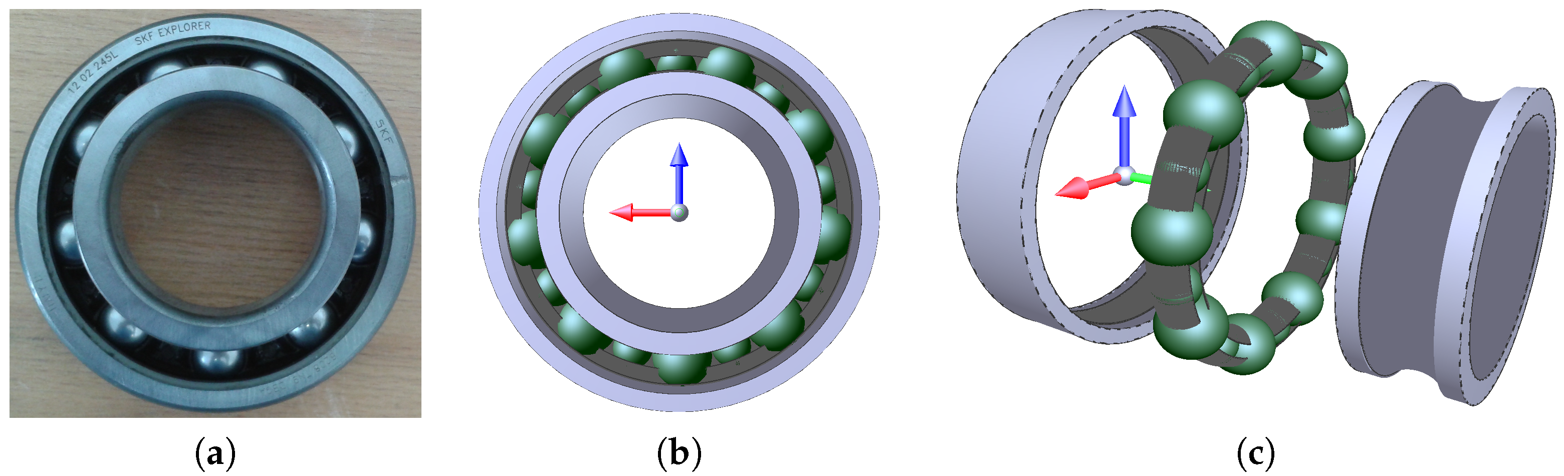
2. Three Dimensional Modelling of Radial Ball Bearing Using DEM

To overcome the 2D modelling limitations from the out-of-plane effects (gyroscopic effect, axial loading, free contact angle, etc.) are ignored [20], we proposed a three-dimensional description of a ball bearing [29] using DEM (Figure 1b) with the aim of investigating the lubrication regime in relation to the kinematic and mechanical operating conditions. The radial ball bearing of 6208 series (SKF 6208 TN9/DBGA) is considered in this study (Figure 1a).
The dimensions and geometrical conformity of the bearing considered are listed in Table 1. The number of balls in contact with the inner and outer raceways is Z = 9 . Nine additional smaller balls of radius R z in contact with two toruses are considered to play the role of a cage (Figure 1c). Even if the cage is different in shape in comparison to the standard form, the design does not at all affect the contact forces between rolling elements and cage [25]. In addition, the proposed description of the cage mainly has two roles. The first is that it ensures a conform internal radial load distribution, while the second is that it allows intermittent rolling elements/cage contacts to be taken into account when the ball bearing operates. However, details should be supplied about the cage in the sense that the only other possible interactions involving the cage elements may be occur between rolling elements.
The ball bearing design performed by DEM allowed us to numerically achieve bearing frequencies, namely FTF, BPFI, BPFO and BSF with a good accuracy and gives the opportunity to take into account all bearing components without any restriction.

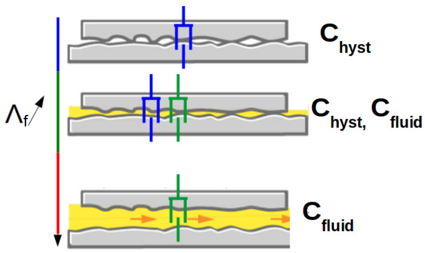
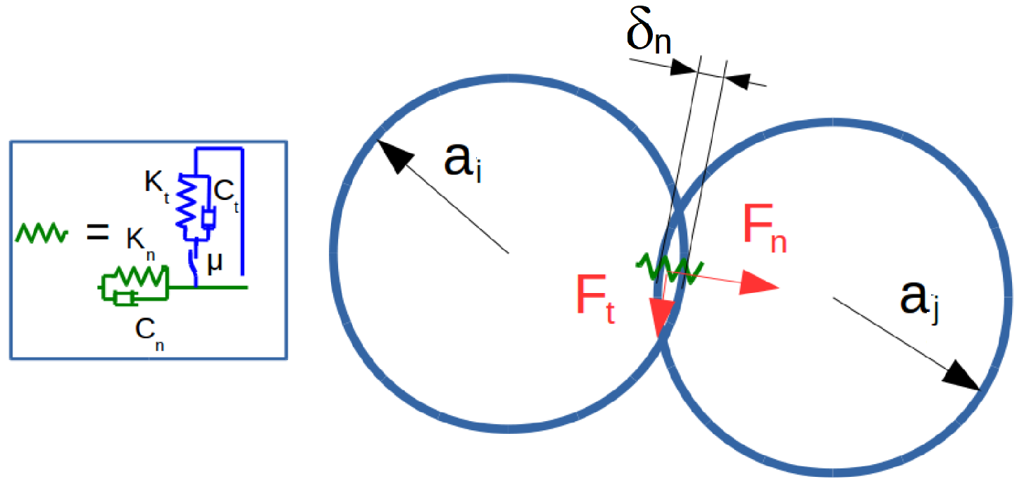
2.1. Contact Stiffness and Damping Effect

The contact stiffness model used in the discrete modelling is based on a smoothed formulation established by Cundall et al. [27]. The contact forces are obtained by means of Kelvin-Voigt Spring-Dashpot Model and a Coulomb’s law if sliding occurs at the contact (Figure 2). The main assumption made with DEM is that the particles in contact are assumed perfectly rigid and therefore, there is no elastic deformation of particles. The elasticity is only considered at the contact between particles.
The contact forces F n , t in normal and tangential directions according to the local frame at the contact plane, are described with an explicit mechanical model depending on elastic force displacement law, Coulomb friction and viscous damping coefficients (Equation (1)).
F n , t = K n , t δ n , t + C n , t v n , t with F t = m i n F t , μ F n × s g n v t
where δ n , t are the normal and tangential relative displacements, K n , t the normal and tangential stiffnesses, C n , t the normal and tangential viscous damping coefficients, v n , t the normal and tangential relative speeds according to the local frame and μ the Coulomb friction coefficient in the case of a sliding contact. The normal viscous damping coefficient C n to ensure a satisfactory mechanical steady state is a function of two damping types, namely hysteretic and elastohydrodynamic, related to the contact shape, roughness, fluid properties, temperature, operating conditions, etc. In considering a reasonable assumption, the expressions of both hysteretic and fluid damping coefficients are discussed later. The tangential viscous damping coefficient C t is more difficult to evaluate. For convenience, the ratio C t C n is considered to range in the interval 0 , 1 . The normal contact stiffness K n is related to mechanical characteristics and curvatures of the surfaces in contact according to non-linear model; F n δ n 3 2 . Considering a rolling element in contact with inner-raceway (or outer-raceway) the normal stiffness is given as function of the curvature sum radius and the approximate elliptic integrals as proposed in [34]:
K n = 2 π k G 2 E ¯ R c u r v e 9 F ¯ 3 δ n 1 2 R c u r v e = R x R y R x + R y R x = R 1 x R 2 x R 2 x ± R 1 x , R y = R 1 y R 2 y R 2 y R 1 y
with R c u r v e the curvature sum radius, R x the effective radius in x direction, R y the effective radius in y direction, k the ellipticity parameter k = α 2 π , α = R y R x , F ¯ the approximate elliptic integral of first kind F = 1 + q l n α , q = π 2 1 and E ¯ the approximate elliptic integral of second kind E ¯ = 1 + q α (Figure 3). The equivalent radius R x is calculated by taking into account the cases of convex contact (ball-inner-raceway) and concave contact (ball-outer-raceway), as given in Equation (2). For the sake of clarity, we note that R b = R 1 x = R 1 y , R 2 x = R i and R 2 y = R r . G = E 2 1 + ν is the shear modulus of steel in the case of identical materials in contact, E the Young’s modulus ( E = 210 GPa) and ν the Poisson’s ratio ( ν = 0.3 ).
When interactions between rolling element and cage ball occur the contact is assumed to be in boundary lubrication regime without friction dissipation and the damping coefficient is considered critical. The normal stiffness is only taken into account, and therefore the following equation is considered [35]:
K n = 4 G R e q 1 ν δ n 1 2
where R e q = r i r j r i + r j is the equivalent radius of two balls in contact of radius r i and r j , respectively. The tangential stiffness is related to the normal stiffness so that the ratio K t K n ranges over the interval [ 2 3 , 1 ] [27]. The tangential stiffness K t can be calculated by means of the normal interaction F n , the curvature radii and the mechanical properties of both rolling element and cage ball [35].
The steady regime of the ball bearing in dynamic mode is achieved with viscous damping and local friction added as dissipative forces to the mechanical model (1). The primal viscous effect is the hysteretic damping coefficient C h y s t in the normal direction n and related to the plastic strain of surface roughness due to the normal interactions (4).
C h y s t = 3 α e K n δ n 2
where α e = 0.08 s·m 1 denotes the restitution coefficient of steel [36]. In the case of a boundary lubrication regime in ball bearing, typically at heavy radial load and low rotation speed, this means that metal-metal contact predominates, involving a high coefficient of friction μ 0.1 .
Bearing, cam mechanisms and gears are considered with non-conformal contacts endowed with EHL regime. Such mechanical systems are often designed for the lubricant film to be thick enough, more than 1 μ m, to avoid contact between the mating surfaces. According to the relation given in [30], the damping coefficient C f l u i d due to the lubrication film in the normal direction of contact is written as follows (5):
C f l u i d = 3 π η a 2 R b h m i n 3 2
with η = 0.04 Pa·s the dynamic viscosity of the fluid at operating temperature and atmospheric pressure [37], a the semi-major axis of the Hertz’s elliptical contact [9], h m i n the minimum fluid thickness of the ball-inner-raceway (or -outer-raceway) contact at an azimuth angle ψ .

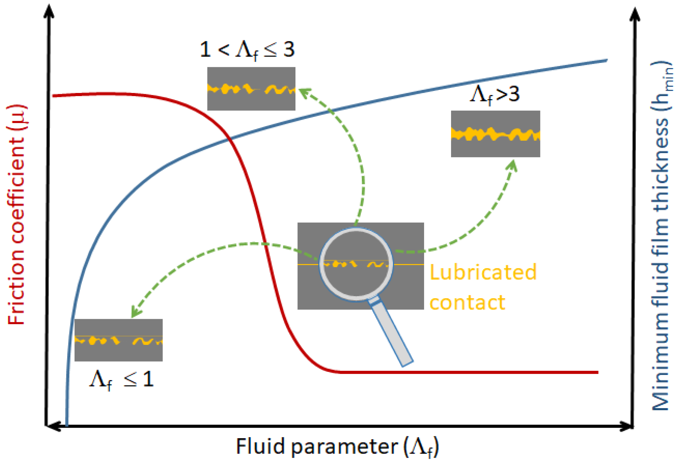
2.2. Fluid Film Thickness and Fluid Parameters

In the field of elastohydrodynamic lubrication, grease rheology influences the fluid film thickness under operating conditions [38]. Given that the viscosity of lubricant increases with respect to pressure, this means that the lubricant exhibits piezo-viscous behaviour. Temperature also plays a role in grease viscosity changes. Taking into account the piezo effects of the fluid, we have, in the discrete modelling, considered the piezo-viscous-elastic regime to evaluate the minimum fluid film thickness h m i n [34]. For hard surfaces in contact, h m i n is expressed according to the following elastohydrodynamic Formula (6):
h m i n = 3.63 U ¯ r 0.68 E ¯ 0.49 W ¯ 0.073 1 e 0.68 k R x
E ¯ , U ¯ r , W ¯ are three dimensionless parameters: E ¯ = ξ E , with ξ the viscosity-pressure coefficient of the lubricant at operating temperature and atmospheric pressure ( ξ = 2.3 × 10 8 m 2 · N 1 ) , E = E 1 ν 2 the effective elastic modulus of steel; U ¯ r = η U r E R x , with U r the rolling velocity; W ¯ = Q ψ E R x 2 , with Q ψ the ball-inner-raceway (or -outer-raceway) normal load (Figure 4).
It should be noted that the deformation of the surface asperities is not taken into account in the fluid film thickness model. Masjedi and Khonsari [10] proposed a curve-fit expression for the film thickness and asperity load ratio in point-contact EHL of rough surfaces, in order to take into account the deformation of surface asperities. In the case of a deep groove ball bearing, the authors obtained a very low asperity load ratio for medium angular shaft speed ( ω s h a f t > 200 rad·s 1 ). However, for a rotational speed of one order of magnitude lower, the asperity load ratio at both outer and inner races reaches a value of the order of 10 % to 12 % . In the context of this work, the numerical simulations are at least performed with angular speed of two orders of magnitude. Therefore, it is reasonable to assume that the roughness deformation slightly affects the fluid film thickness.
Commonly, a simply way to identify which lubrication regime a system is running in is by the use of a dimensionless parameter, Λ f , proposed by Tallian and called the fluid parameter [39]. Λ f is the ratio of the minimum fluid film thickness to the surface roughness. This parameter is also related to the friction coefficient μ as shown through a schematic representation of the Stribeck curve [11] for non-conformal contact (Figure 5).
Λ f = h m i n ( Q ψ , ω ) 1.25 × σ a 1 2 + σ a 2 2 h m i n ( Q ψ , ω ) 3.75 × 10 7
where ω is the shaft angular speed (i.e., inner ring), σ a 1 and σ a 2 denotes the arithmetic mean roughnesses of the measured surfaces for the inner-raceway (or outer-raceway) and rolling elements, respectively. The finishing process known as “Superfinishing” enables surface condition values of a dozen nanometres [40,41]. We assume that the races have σ a 1 3 × 10 7 m and rolling element roughness can be neglected σ a 2 < < σ a 1 . Ball-on-disk tests, known as tribometer usually involve similar orders of magnitude [15,42].
At fully flooded condition, the normal damping coefficient C n is strongly dependent on the EHL regimes. Since the rheology of the fluid is taken into account through the assumption of a piezo-viscous-elastic model, we postulate that regimes simulated under the considered operating conditions do not increase K n with an additional fluid film stiffness by considering K n ( Λ f ) [30]. As long as the mechanics of the surfaces are responsible for the stiffness of the component, within the piezo-viscous-elastic limits, the film parameter allows us to select the “predominant” viscous damping C n ( Λ f ) according to the following Table 2.
When the applied load is mainly carried by asperities of the surfaces in contact, this means that only the hysteretic effect plays a role in normal damping, C n = C h y s t . In mixed lubrication regime the normal damping C n is considered to be a function of both hysteretic and fluid damping. By assuming that the two effects act in parallel, then C n = C h y s t C f l u i d C h y s t + C f l u i d . In the case of fully developed lubrication film, the hysteretic effect is not possible and only the fluid effect remains, so C n = C f l u i d . Figure 6 gives an illustration of viscous damping status according to the fluid parameter Λ f .
This approach might appear simplistic in view of the complexity of the mechanisms put into in play at a lubricated contact. Nevertheless, this postulate is also correlated with the electromechnical analysis of a lubricated contact, where electrical contacts between asperities are resistive and the electrical response of the fluid film is capacitive [21]. The electrical circuit of an apparent contact behaves as a parallel RC circuit according to the lubricated regime. The dissipative properties of a contact are updated according to the lubrication regime. To do this, it was necessary to identify the fluid parameter Λ f as a discriminant.

2.3. Space and Time Discretization of the DEM Ball Bearing Model

To perform numerical simulations using DEM, we assumed that the friction coefficient μ ( Λ f ) ranges over the interval 0.01 , 0.1 as for the case of rolling/sliding concentrated contacts [43]. Typically, μ = 0.1 for Λ f < 1 , which means that the applied load is completely carried by the asperities of the contacting surfaces. When Λ f increases up to 1, μ decreases considerably passing from 0.1 to 0.01 . In this range, the mixed regime is reached so that the applied load is carried by both lubricant film and asperities of the contacting surfaces. If Λ f becomes greater than 3 the fully fluid regime is established and the friction coefficient is kept constant, μ = 0.01 . However, it should be mentioned that the friction coefficient is usually assumed constant in numerical simulations by DEM. Taking the fact that the lubricated contacts in a ball bearing must be considered individually, namely with their own friction coefficient and viscous damping, therefore, this can be achieved through an identification on the Strikeck curve by means of the fluid parameter Λ f . This can be done through a linear fitting made on the Stribeck curve (Figure 5). From a numerical standpoint, at a given time step of DEM simulation, the kinematic and mechanical conditions are known at each contact (rolling speed, relative speed, normal load), so that the lubrication regime may individually be determined through the fluid parameter expression (7). Hence, the friction coefficient μ ( Λ f ) and the viscous damping C n ( Λ f ) are calculated to carry out mechanical resolution for the next time step.
We note that regarding the direction t , the effect of the tangential damping C t , in the context of radial ball bearing, is assumed to be weaker than the normal damping and could be then neglected. Therefore, following the tangential direction the dissipation is basically related to the friction coefficient μ .
The contact stiffness model based on the elliptic integrals and damping model related to lubrication regimes described above, are implemented in the numerical tool using DEM. Therefore, Equation (1) is rewritten under the following form (8):
F n = K n δ n + C n ( Λ f ) v n F t = m i n ( K t δ t , μ ( Λ f ) F n ) × s i g n ( v t )
In Equation (8), the coefficient of friction μ ( Λ f ) is then considered as function of the fluid parameter Λ f . It should, however, be stated that the correlation of the operating conditions to the friction coefficient remains difficult to apprehend numerically. M. Björling et al. [44] studied numerically and experimentally the variation of the friction coefficient at different Slide-to-Roll ratios (SRRs) and drive speeds. Guegan et al. [42] also investigated friction and film thickness in elastohydrodynamic contacts through different Stribeck curves, where the authors achieved a dependency on the SRRs and drive speeds. In fact, and based on these results, it seems crucial to be aware of the dependence of friction coefficient on the operating conditions.
The DEM modelling is by solving Newton’s second law for each rolling element. Equation (9) takes into account dynamical effects of rolling elements, such as centrifugal forces and gyroscopic effects, when the bearing is functioning.
m i u ¨ i = F i e x t + j F j i I i θ ¨ i = M i e x t + j M j i
where the subscript i denotes a given rolling element (or cage element). m i and I i are the mass and the quadratic moment of inertia. u ¨ i and θ ¨ i are the linear and angular accelerations. F i e x t and M i e x t are the external force and moment acting on element i. F j i and M j i are the reaction force and moment interaction of the element j on the element i.
The mechanical resolution of ball bearing, composed of 2 × Z balls (rolling and cage elements), requires an explicit time integration based on the velocity-Verlet scheme (10).
u ( t + Δ t ) = u ( t ) + Δ t u ˙ ( t ) + Δ t 2 2 u ¨ ( t ) u ˙ ( t + Δ t ) = u ˙ ( t ) + Δ t 2 u ¨ ( t ) + u ¨ ( t + Δ t )
where u , u ˙ are the displacement and velocity vectors, respectively, t the current time and Δ t the integration time step. The numerical simulations are conducted with Δ t of 1 μ s. Choosing a large time step induces numerical instabilities and moreover it does not allow a steady mechanical state to be achieved.
The effectiveness of the DEM lies in the fact that a discrete formulation allows each contact (ball-inner-raceway, ball-outer-raceway or ball-cage) to be easily tracked instantaneously when the ball bearing under operating conditions is simulated. Before studying the lubrication regime when the ball bearing operates under dynamical conditions, we first carried out a quasistatically loaded ball bearing to investigate the validity of the numerical response. The loading protocol of the ball bearing is of prime importance in performing realistic simulations in accordance with standard theoretical models for bearings as described in [34,45]. Parameters related to the normal loading and radial deflection in ball bearing together with numerical results are introduced and discussed in Appendix A.

3. Numerical Prediction of Lubrication Regimes in Operating Radial Ball Bearing

As the relevance of the DEM is clearly established for accurately predicting the mechanical state in a radial ball bearing (Appendix A), we will now focus on the lubrication regimes under operating conditions. Ball bearings require fluid lubrication in order to perform satisfactorily for long periods time. Elastohydrodynamic lubrication (EHL) theory is concerned with the formation of a thin fluid film at the contact area between rolling elements and raceways [9,46]. Under favourable conditions of mounting, speed rotation, loading and fluid viscosity, the lubricant film is assumed sufficiently thicker to separate the rolling surfaces. Obviously, the rolling bearings operating under a fully fluid regime have significant reduction of wear, and therefore, the expected bearing lifetime will be much longer than in the case of bearings operating in boundary lubrication regime. Generally, the minimum thickness of the fluid film is of the order of the roughness; nevertheless, in the case of optimal conditions at high speed and adequate viscosity, the fluid film exceeds the size of the surface asperities so that a fluid film thickness of several micrometers can be reached, 3 to 10 × σ a [47,48].
In this section, numerical simulations carried out with MULTICOR-3D software will be discussed. The lubrication regimes of a radial ball bearing under operating conditions are investigated by taking into account both imposed mechanical loading and fixed kinematic conditions. Sensitivity analyses are performed on the main driven parameters, namely the radial load F r , the diametral clearance P d and the angular speed ω of the inner ring, which more or less may affect the lubrication regime.

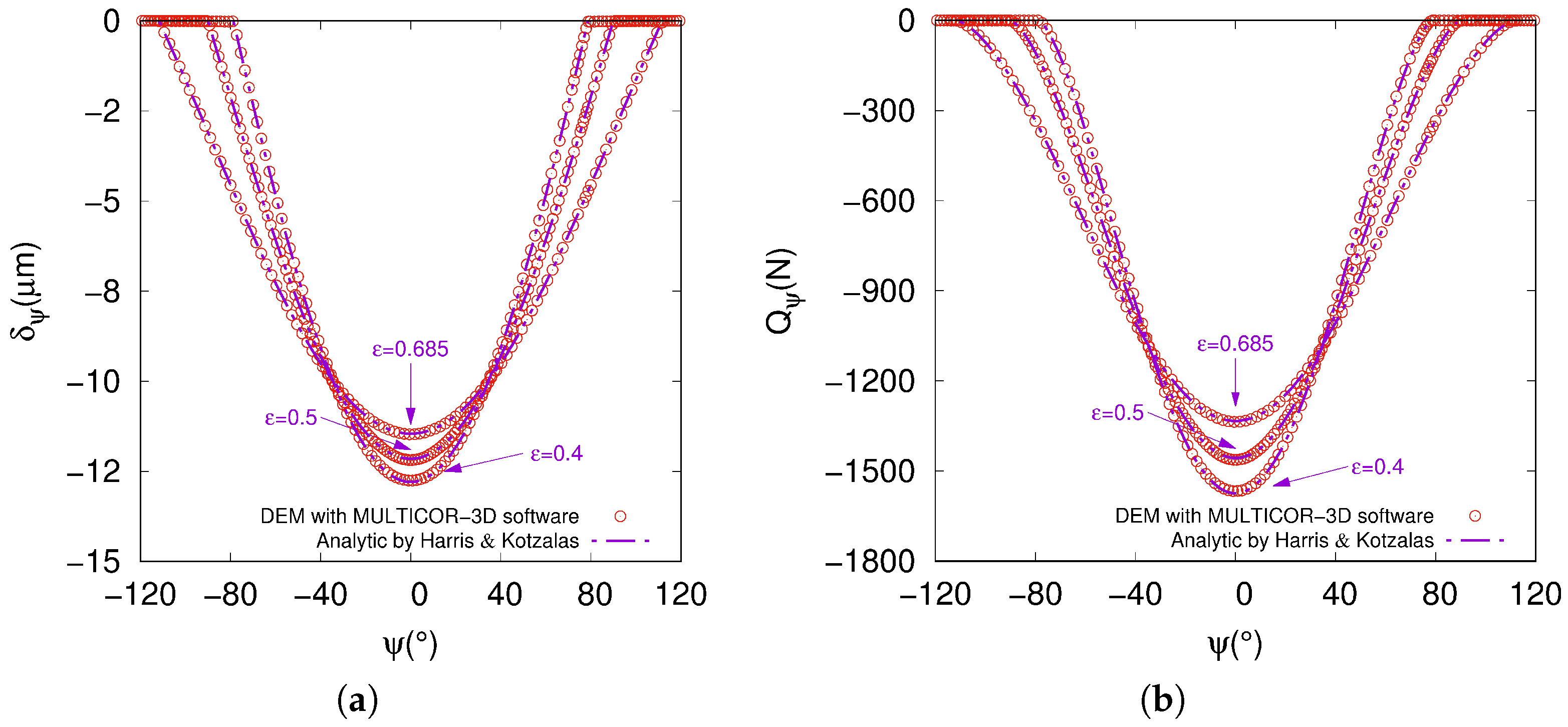
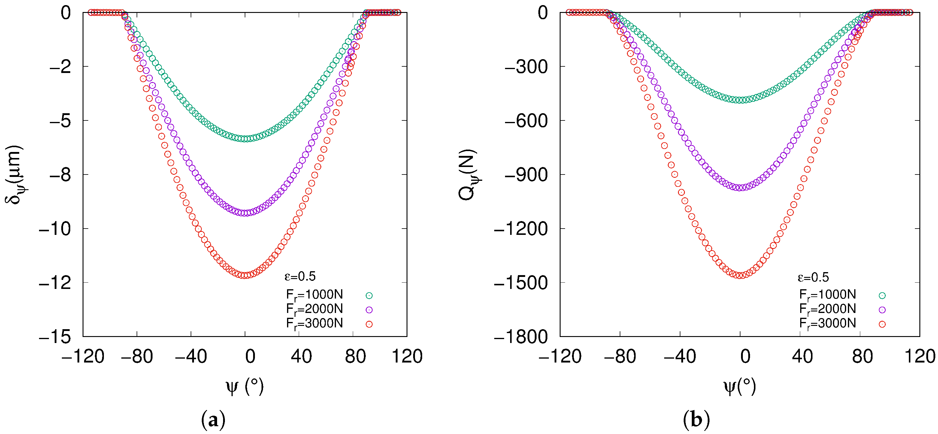
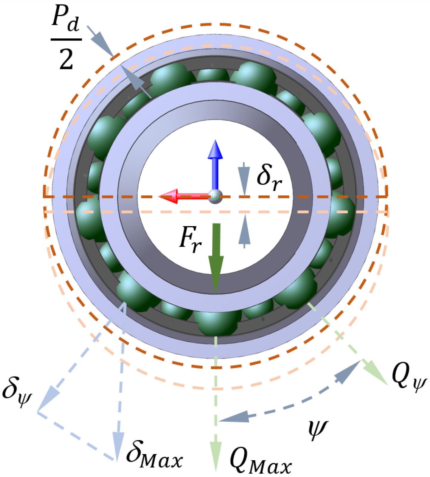
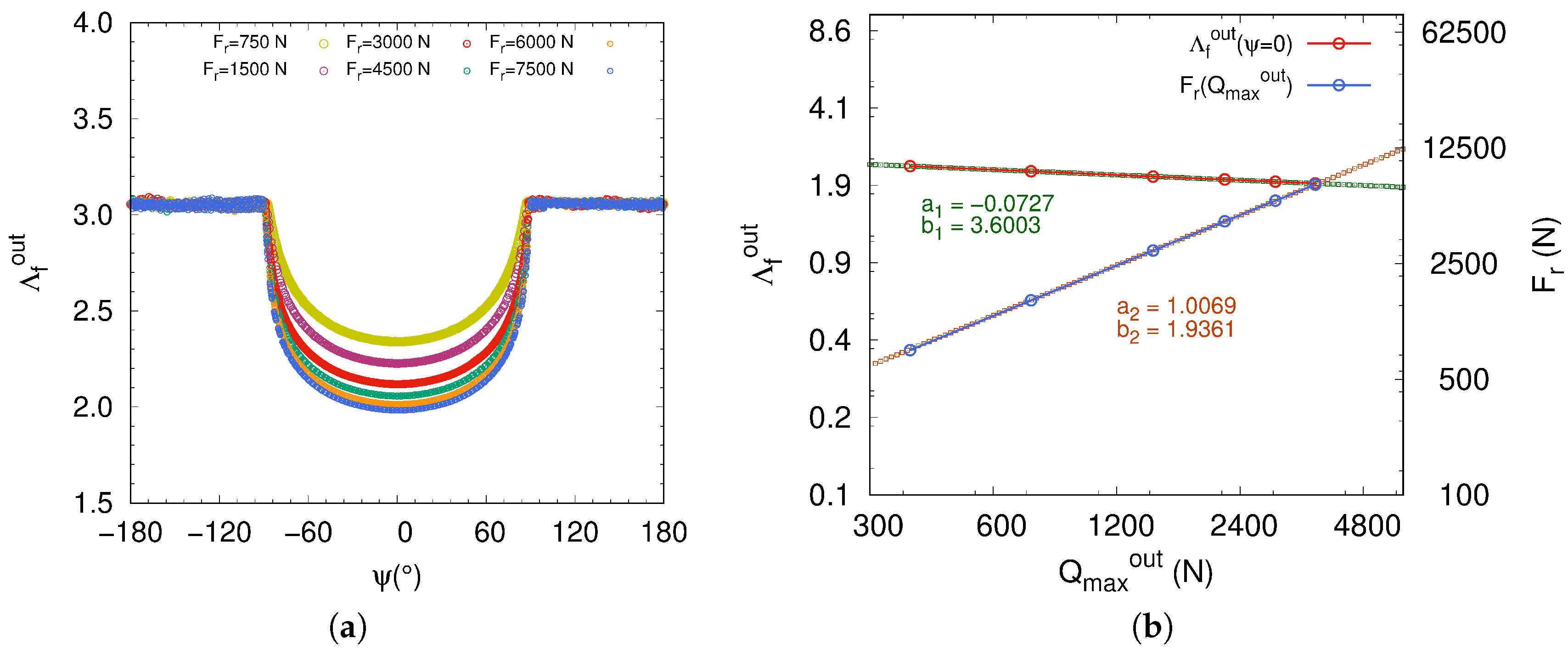
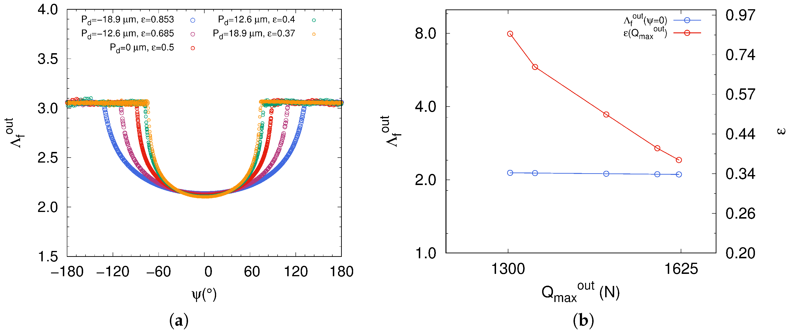
3.1. Effect of Radial Load and Diametral Clearance

The lubrication regime related to the film parameter Λ f ψ is identified on a given rolling element at each azimuth angle ψ ( t ) with respect to time t. A rolling element at an initial azimuth angle ψ 0 is considered and followed during the simulation. The tracked rolling element exactly reflects the lubrication regime of the radial ball bearing, from the starting phase, when the rotation is imposed on the inner ring, until the slowdown phase after going through the steady phase. The three phases are then studied to investigate the lubrication regime.
As an example, numerical simulation, aimed to check the efficiency of the discrete formulation, is initially conducted with the following conditions: ω = 500 rad·s 1 , P d = 0 ε = 0.5 and F r = 3000 N. For the sake of conciseness, we have only been interested in lubrication regimes at the contact interface between rolling elements and the outer-raceway. Obviously, the same numerical analysis can be done for the rolling elements in contact with the inner-raceway. In the steady state, the theoretical expression for angular speed in pure rolling, is given by ω b a l l = ω × R i 2 × R b . Under the above kinematic conditions, the expected analytic solution of the angular speed of the rolling element is ω b a l l = 952.38 rad·s 1 . Figure 7a depicts the variations of both shaft and ball angular speeds as a function of time. The solid curve depicts the angular speed of the shaft during the start-up phase (in royalblue), steady phase (in red) and slowdown phase (in dark-yellow). The dashed curve depicts the ball angular speed for the same operating phases. The discrete model of the radial ball bearing achieves numerical results in good agreement with analytic solution.
The SRR is calculated and plotted for a single rolling element in order to track the status of the rolling element/inner-receway contact, inside and outside the loaded zone of the ball bearing, at start-up, steady and slowdown phases (Figure 7b). The SRR is very low because the rolling element has a pure rolling regime when the steady state is reached, except for start-up and slowdown regimes. Obviously, the SRR of the rest of the rolling elements is just the same that for the plotted one.
The transition from one lubrication regime to another at the ball-outer-raceway contact is well depicted in Figure 8a,b. The plotted curves exhibit the fluid film thickness changing, starting from the start-up phase to the slowdown one, passing through the steady phase. The fluid film thickness h m i n o u t increases from zero to steady values (curve in royalblue), corresponding to the start-up phase, while for the slowdown phase (curve in dark-yellow), h m i n o u t decreases from steady values to zero. The steady regime plotted in red describes the transition of the rolling element from the loaded zone (low value of h m i n o u t ) to the unloaded zone (high value of h m i n o u t ). When the steady regime is reached the h m i n o u t (curve in red) is still the same for each contact occurring between rolling element and outer-raceway, inside and outside the loaded zone. For these operating conditions for both start-up and slowdown phases the lubrication regime in the ball bearing changes according to the fluid parameter Λ f , so the value ranging of Λ f is between 0 to 3. However, the ball bearing only operates in mixed regime when the steady phase is reached, with Λ f varying between 2.15 and 3.
On the other hand, in Figure 8a,b at the steady phase we observe the influence of the loaded zone on the fluid film thickness and the fluid parameter, h m i n o u t and Λ f o u t , respectively. The fluid film thickness decreases for ψ ranging over the interval π 2 , π 2 in accordance with the load parameter ε = 0.5 . The minimum value of h m i n o u t is reached at ψ = 0, ( h m i n o u t < 1 μ m), in accordance with the applied radial load F r . Consequently, the numerical simulation using DEM may be considered as an efficient predictive tool for monitoring the transition between lubrication regimes in ball bearings and in operating conditions.
Secondly, we are now interested in the radial load effect on the lubrication regime in a ball bearing. The operating conditions and the diametral clearance are kept the same, with ω = 500 rad·s 1 and P d = 0 ε = 0.5 . We have only considered the steady phase and lubricated ball-outer-raceway contact for each simulated radial load F r . We assumed that both outer and inner contacts achieve similar lubrication regimes in the loaded zone of ball bearing for a fixed angular speed. Numerical simulations have carried out for six values of F r ranging in the interval 750 N , 7500 N .
In Figure 9a is plotted the fluid parameter for all the simulated radial loads with respect to fixed operating conditions. It turns out that F r does not play a significant role because the lubrication of the ball bearing is still in mixed lubrication regime the radial load. This is well observed in Figure 9b on a logarithmic scale, where the fluid parameter Λ f o u t decreases slightly with increasing maximum normal load Q m a x as function of the radial load F r . In addition, the fit made on the curve of the fluid parameter Λ f o u t , as a function of the maximum normal load Q m a x , leads to a linear regression with a negative slope a 1 of 0.0727 . This value is expected since it is related to the EHL model through the dimensionless parameter W ¯ raised to the power 0.073 . Also, the second fit made on the curve depicted the variation of F r with respect to Q m a x leads to a slope a 2 very close to 1, which is in good agreement with Equation (A3).
Thirdly, we have studied what effect the diametral clearance has on the fluid film thickness. The numerical simulations that we have conducted on the radial ball bearing with variation of diametral clearances aim to study the fluid film spread according to variation of the loaded zone. Both negative and positive diametral clearances are taken into account in the ball bearing model. Numerical simulations have been carried out for several values of P d . The same operating conditions are considered, namely shaft angular speed ω = 500 rad · s 1 and radial load F r = 3000 N.
In view of the curves plotted in Figure 10a of the fluid parameter Λ f o u t , the diametral clearance P d does not notably affect the lubrication regime. In addition, Λ f o u t clearly describes a plateau at azimuth angle ψ = 0 (Figure 10b). However, the fluid parameter distribution differs considerably in shape when the diametral clearance varies, passing from positive values to negative values. Indeed, passing from a negative value of P d to a positive one, it directly affects the fluid parameter with respect to azimuth angle ψ of rolling element. The loaded zone of the ball bearing with a diametral preload P d < 0 , ε > 0.5 is larger than the case with a diametral clearance P d > 0 , ε < 0.5 (Figure 10a). Inversely, the maximum normal load Q m a x increases when a diametral clearance is considered (Figure 10b). In such a mechanical configuration, we have an overloading in the ball bearing with a reduction of the loaded zone size. Therefore, the ball bearing operates under severe conditions that could potentially induce early wear mechanisms because of the concentration of normal load Q m a x in the loaded zone. Moreover, the manufacturers advise users to avoid the case with a load parameter ε < 0.5 because of the risk of premature degradation of ball bearings. It is admitted by the manufacturers of bearings, that the lifetime of the components is optimized, provided that the mounting is done with a zero clearance P d = 0 , ε = 0.5 and a sufficient lubricant amount.
One can state that the radial load F r , the diametral clearance P d > 0 and the diametral preload P d < 0 do not have a significant effect on the lubrication regime. As shown by the previous numerical simulations, when the operating steady phase is reached in the ball bearing, no change is expected in the established EHL regime.

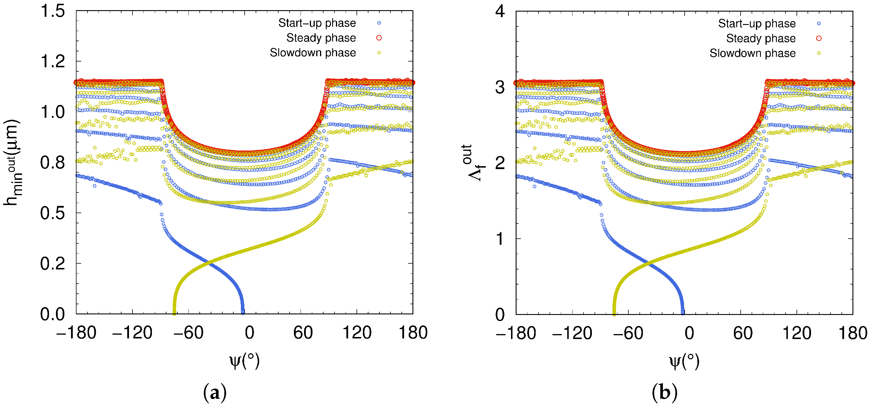
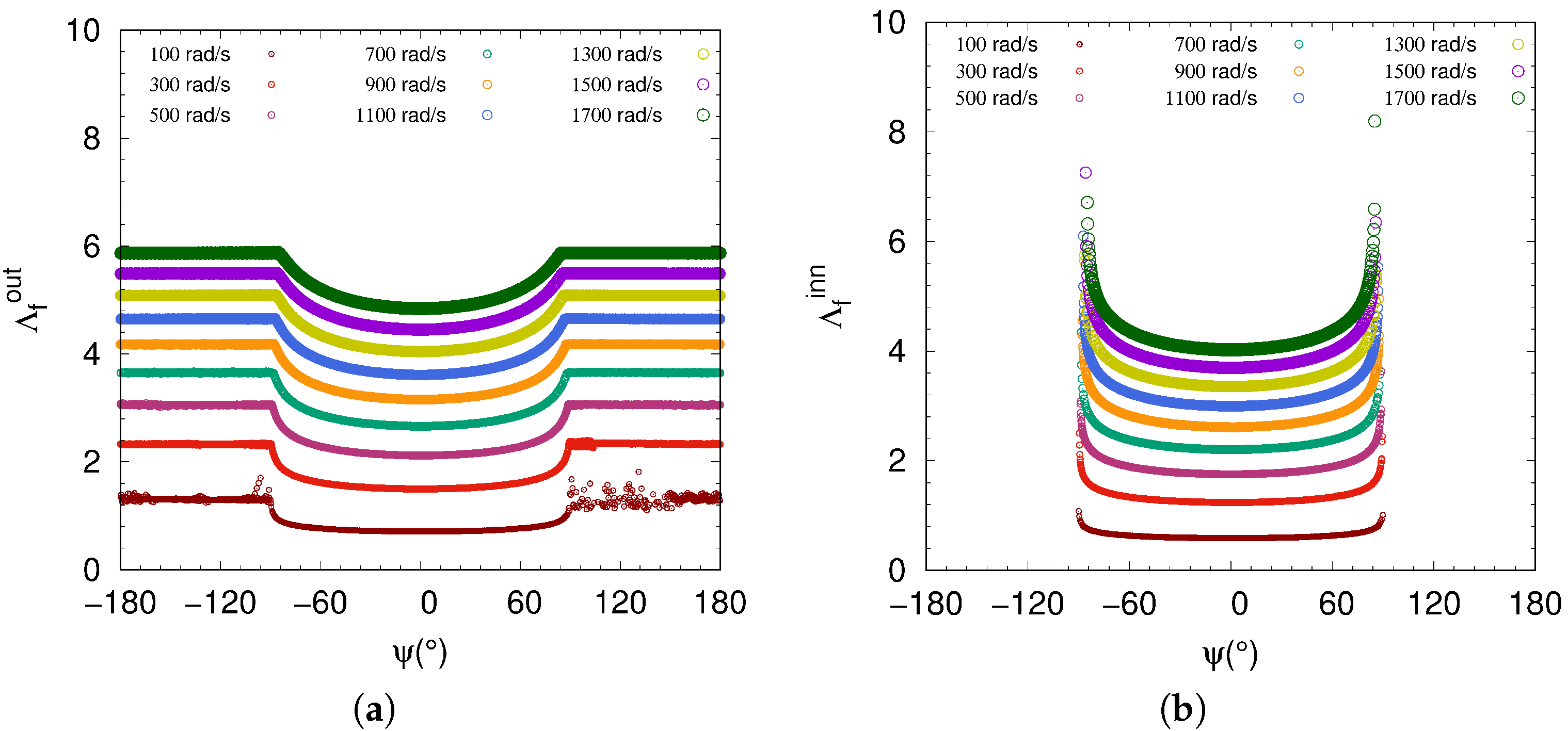
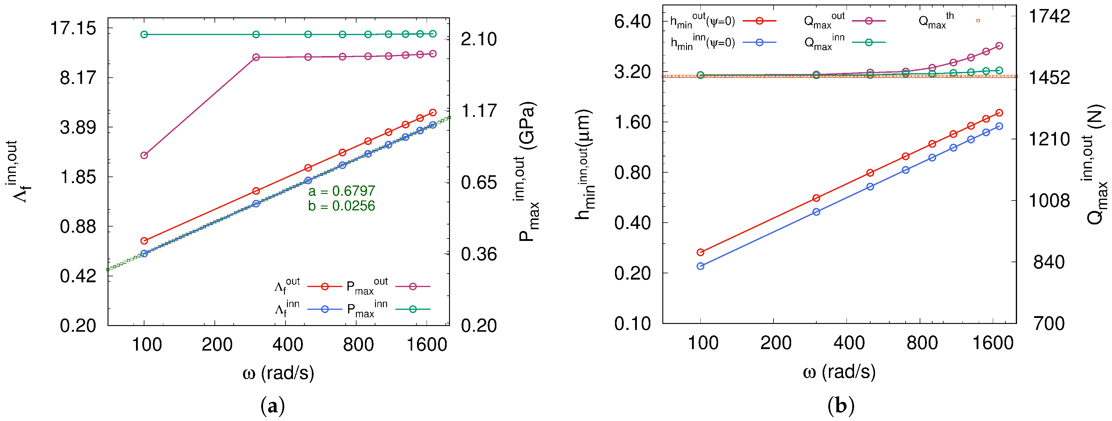
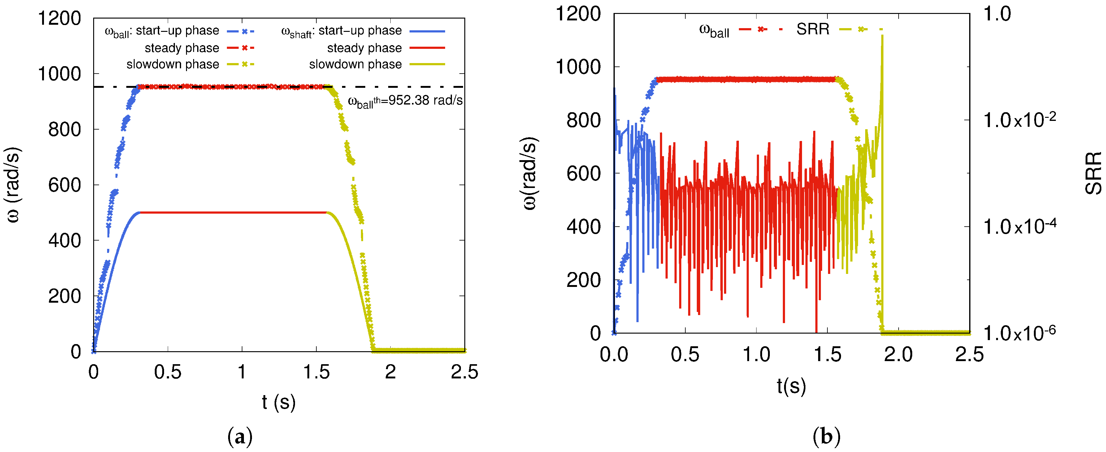
3.2. Effect of Angular Speed

We are now interested in the influence of the shaft angular speed on the lubrication regime of the radial ball bearing. The angular speed ω (rad·s 1 ) ranges over the interval 100 , 1700 and varies in steps of 200. A radial load F r of 3000 N and a zero clearance P d = 0 , ε = 0.5 are considered. The lubrication regimes are investigated for both ball-inner-raceway and ball-outer-raceway contacts. We anticipate that the lubrication regime will be more sensitive to the angular speed of the shaft this time as well because the lubricant gains in lift. The viscosity and the rolling speed have more significant effects on the minimum fluid film thickness h m i n as indicated by Equation (6). We note that the rolling velocity U r is for pure rolling; the relative sliding velocity is assumed negligible. However, if the sliding velocity becomes significant then the dimensionless rolling velocity U ¯ r is expressed as a function of both rolling and sliding velocities [37].
In addition, the fluid film thickness at the contact with the outer-raceway can be estimated at each revolution of the inner ring. Indeed, because of centrifugal effects the contacts are persistent between the rolling elements and the outer ring (Figure 11a). Furthermore, a disturbance of the fluid film thickness is observed at ω = 100 rad·s 1 in particular when the rolling element is outside the loaded zone. This effect is mainly due to changes in rolling velocity of the ball. However, when the angular speed of the inner ring becomes higher and higher, allowing the rolling element to reach a more steady velocity, the disturbance totally disappears. On the other hand, because of the load parameter ε = 0.5 , corresponding to zero clearance P d = 0 , the fluid film thickness at the contact with the inner-raceway can only be predicted within the loaded zone varying in the interval π 2 , π 2 (Figure 11b). Hence, we have loss of contact with the rolling element in the unloaded zone. Obviously, the latter is kept under a lubrication regime due to the switching with the loaded zone even if the fluid parameter Λ f i n n is not predicted numerically.
The numerical simulations conducted on radial ball bearings allow us to distinguish between the lubrication regimes for both ball-outer-raceway and ball-inner-raceway contacts. As is well depicted in Figure 11a,b, the film parameter Λ f i n n related to the fluid film thickness at the ball-inner-raceway contact is lower because the equivalent radius of convex curvatures is lower than that of concave curvatures Λ f i n n < Λ f o u t . Indeed, the comparison of the inner and the outer dimensionless loads W ¯ i n n , o u t , upon which depends Equation (6), indicates a higher value for the ball-inner-raceway contact (Figure 12a). These results in higher contact forces act on the fluid film thickness and lead to a maximum pressure at the convex contact with the inner-raceway. Hence, it is sufficient to estimate the fluid film thickness h m i n i n n at the contact with the inner-raceway to predict the lubrication regime. Nevertheless, for a ball bearing operating at high speed, the centrifugal force of the rolling element is added to the normal force at the contact with the outer-raceway. The fluid film thickness h m i n o u t may be only estimated at the contact with the outer-raceway. This centrifugal effect is clearly observed in Figure 12b at the ball-outer-raceway contact where the maximum normal load Q m a x increases in comparison to the ball-inner-raceway contact, where Q m a x remains close to the analytic solution in static mode, with Q m a x t h = 1457 N. Moreover, the fit made on the curve of the fluid parameter Λ f i n n , as function of the angular speed of shaft ω (Figure 11a), achieves a linear regression with a positive slope a of 0.6797 . This value is very close to the exponent of the dimensionless term of the EHL model, related to the rolling velocity U ¯ r 0.68 . This confirms once again that the DEM approach is well done, and above all allows fast monitoring of the lubrication regime of the ball bearing under operating conditions.
In Table 3 are summarized the lubrication regimes with respect to imposed angular speed. We remark when the ball bearing operates at a specific angular speed ω the rolling elements may simultaneously be under two lubrication regimes. For example, in the case of ω in the interval 900 , 1700 , we have at the same time both mixed and fully fluid regimes at the inner-raceway and outer-raceway contacts, respectively (Table 3). Unlike the cases when radial load F r and diametral clearance P d are considered to study their influence on the lubrication regime, the imposed angular speed plays a more significant role in lubrication regime transition. The EHL model is more sensitive to the rolling speed since the dimensionless rolling velocity U ¯ r 0.68 prevails over the dimensionless load W ¯ 0.073 .

4. Conclusions and Perspectives

Through this study we wanted to highlight the relevance of the DEM approach in describing the dynamic behaviour of multicontact systems such as rolling bearings. Under a quasi-static radial load, the proposed discrete description of a radial ball bearing, using a contact stiffness model based on elliptic integrals, achieves very similar radial deflection and normal load distributions in comparison to analytic formulation [45]. The implementation of the discrete model in the MULTICOR-3D software allowed us to investigate the lubrication regimes from a qualitative point of view under operating conditions. Moreover, in the context of the EHL study, the DEM has proven to be a useful numerical tool since it enables continuous prediction of the lubrication regimes and dynamic management of the contact interface. By driving various parameters to be investigated, such as the radial load, diametral clearance and shaft angular speed, it has clearly been shown that the lubrication regime is basically dependent on the angular speed of the inner ring. In other words, the transition between the different lubrication regimes is mainly related to the rolling speed at the lubricated contact in the loaded zone of the ball bearing. As shown in figures consecutive to the parametric study, once the ball bearing reaches the steady state, both the radial load and diametral clearance have a minor effect on the lubrication regime. Starting from the mechanical behaviour at the contact interface and lubrication regime identification, the proposed discrete modelling may be extended to further studies, for example, dealing with a ball bearing operating under abnormal load or noisy kinematic conditions. In fact, such undesirable defects appear often when ball bearings are subjected to extreme operating conditions, typically under heavy loadings, in the presence of severe shocks, or in case of inadequate mounting. Furthermore, the innovative monitoring method recently developed and based on electrical measurements [20] may be also performed for ball bearing diagnosis taking into consideration the capacitive behaviour or the dielectric properties of the lubricant. In addition, thermal effects due to the operating conditions of the rolling bearing involve significant modifications of the lubricant properties, in terms of viscosity and contamination by debris. These thermal aspects must also be considered in the discrete modelling to investigate the lubricant aging effects on the lubrication regime.

Author Contributions

Conceptualization, M.G. and C.M.; Methodology, M.G.; Software, M.G.; Validation, M.G. and C.M.; Formal Analysis, M.G.; Investigation, M.G. and C.M.; Resources, M.G. and C.M.; Data Curation, M.G.; Writing—Original Draft Preparation, M.G.; Writing—Review & Editing, M.G. and C.M.; Visualization, M.G. and C.M.; Supervision, M.G.; Project Administration, M.G.; Funding Acquisition, M.G.

Acknowledgments

We would like to thank the “Région des Hauts-de-France” and the "FEDER” for funding this work.

Conflicts of Interest

The authors declare no conflict of interest.

Nomenclature

αeRestitution coefficient of steel
δrRadial shift
δn,tNormal/tangential relative displacement
ηDynamic viscosity of the fluid
ΛfFluid number
μFriction coefficient
vPoisson’s ratio of steel
wShaft/inner-ring angular speed
E ¯ Approximate elliptic integral of second kind
F ¯ Approximate elliptic integral of first kind
ψAzimuth angle
δa1,2Roughness parameter
εLoad parameter
ξViscosity-pressure coefficient of the lubricant
aRestitution coefficient of steel
Cn,tNormal/tangential viscous damping coefficient
EYoung’s modulus of steel
EEffective elastic modulus of steel
FrApplied radial load
GShear modulus of steel
hminSemi-major axis of the Hertz’s elliptical contact
JrRadial integral
kEllipticity parameter
Kn,tContact normal/tangential stiffness
PdDiametral clearance
QmaxMaximum normal load at ψ = 0
RbRolling element radius
RcCurvature radius of inner/outer raceway
RiInner ring radius
RoOuter ring radius
RzCage element radius
RcurveCurvature sum radius
UrRolling velocity
vtSliding velocity
ZNumber of rolling elements

Appendix A. Normal Load and Radial Deflection in Radial Ball Bearing

For a rigidly supported ball bearing under a radial load F r , the radial deflection δ ψ at an azimuth angle ψ is given by (Figure 4):
δ ψ = δ r c o s ψ 1 2 P d
with δ r the inner-ring radial shift. According to the standard theory, the mechanical state of a bearing is provided by a dimensionless load parameter, ε = 1 2 1 P d 2 δ r , related to the diametral clearance/preload P d and the inner-ring radial shift δ r . The dimensionless load parameter ε reflects schematically the percentage of rolling elements that are put in play by the radial load F r . From a deformation point of view, the radial ball bearing may be in one of the following three configurations: diametral preload P d < 0 , ε > 0.5 , zero clearance or zero preload P d = 0 , ε = 0.5 and diametral clearance P d > 0 , ε < 0.5 . The ball-inner-raceway (-outer-raceway) normal load Q ψ at an azimuth angle ψ is determined as function of the load parameter ε such that:
Q ψ = Q m a x 1 ( 1 c o s ψ ) 2 ε 3 / 2
where Q m a x is the maximum normal load at ψ = 0 . For a radial ball bearing with zero clearance under radial load F r , Stribeck [11] determined that:
Q m a x = F r Z J r ε
with Z the number of rolling elements Z = 9 and J r the radial integral. For example, for a radial ball bearing with zero clearance P d = 0 , ε = 0.5 the radial integral J r is of 0.2288 [45].
To validate the discrete model of a radial ball bearing, numerical simulations are performed with MULTICOR-3D software under quasistatic loading. Figure A1a,b exhibit the radial deflection δ ψ and the normal load Q ψ plotted with respect to azimuth angle ψ of rolling element. Three types of clearance are considered, ε = 0.685 , ε = 0.5 and ε = 0.4 which corresponds to three configurations with negative clearance P d = 12.6 μ m , zero clearance P d = 0 and positive clearance P d = 12.6 μ m , respectively. The azimuth angle ψ of the rolling element is varied by driving the inner ring at a slow angular speed ( ω = 1 rad·s 1 ) to avoid any centrifugal effect. One can conclude that the discrete element approach achieves results very close to the analytic solution given in [45]. As a reminder, lubrication does not have a significant effect in this validation study because of the quasi-static assumption, which means only the boundary regime may be expected, involving the hysteretic damping coefficient C h y s t and friction coefficients μ of 0.1 .
Figure A1. (a) Radial deflection δ ψ and (b) normal load Q ψ distributions under radial load F r = 3000 N.
Lubricants 06 00046 g0a1
In Figure A2a,b are plotted both radial deflection δ ψ and normal load Q ψ for radial load F r starting at 1000 N and increasing in steps of 1000 N up to 3000 N. The numerical simulations achieve a mechanical state in the radial ball bearing in good agreement with analytic formulation. The more radial load F r there is, the larger the radial deflection δ ψ and normal load Q ψ . To prove the efficiency of the DEM approach, a simple assessment can be made on δ ψ and Q ψ at ψ = ± π 2 with zero clearance P d = 0 , ε = 0.5 . In accordance with Equations (A1) and (A2), the numerical simulations lead to δ ψ = ± π 2 = 0 and Q ψ = ± π 2 = 0 , which is nicely shown in Figure A2a,b.
Figure A2. (a) Radial deflection δ ψ and (b) normal load Q ψ distributions under several radial load F r .
Lubricants 06 00046 g0a2

References

  1. Sapietová, A.; Dekýǎ, V. Dynamic analysis of rotating machines in MSC.ADAMS. Procedia Eng. 2016, 136, 143–149. [Google Scholar] [CrossRef]
  2. Zezulka, F.; Marcon, P.; Vesely, I.; Sajdl, O. Industry 4.0—An Introduction in the phenomenon. IFAC-Pap. Online 2016, 49, 8–12. [Google Scholar] [CrossRef]
  3. Ahuett-Garza, H.; Kurfess, T. A brief discussion on the trends of habilitating technologies for Industry 4.0 and Smart manufacturing. Manuf. Lett. 2018. [Google Scholar] [CrossRef]
  4. Chen, J.; Randall, R.B. Intelligent diagnosis of bearing knock faults in internal combustion engines using vibration simulation. Mech. Mach. Theory 2016, 104, 161–176. [Google Scholar] [CrossRef]
  5. Glowacz, A.; Glowacz, W.; Glowacz, Z.; Kozik, J. Early fault diagnosis of bearing and stator faults of the single-phase induction motor using acoustic signals. Measurement 2018, 113, 1–9. [Google Scholar] [CrossRef]
  6. Kompella, K.D.; Rao, M.V.G.; Rao, R.S. Bearing fault detection in a 3 phase induction motor using stator current frequency spectral subtraction with various wavelet decomposition techniques. Ain Shams Eng. J. 2017. [Google Scholar] [CrossRef]
  7. Júnior, J.J.D.S.; de Farias Maribondo, J. Analysis of lubricating oils in shear friction tests using infrared thermography. Infrared Phys. Technol. 2018, 89, 291–298. [Google Scholar]
  8. Hamrock, B.; Dowson, D. Isothermal elastohydrodynamic lubrication of point contacts: Part 1-theoretical formulation. J. Tribol. 1976, 98, 223–228. [Google Scholar] [CrossRef]
  9. Hamrock, B.J.; Dowson, D. Ball Bearing Lubrication: Elastohydrodynamics of Elliptical Contacts; John Wiley & Sons Inc.: New York, NY, USA, 1981. [Google Scholar]
  10. Masjedi, M.; Khonsari, M. On the effect of surface roughness in point-contact EHL: Formulas for film thickness and asperity load. Tribol. Int. 2015, 82, 228–244. [Google Scholar] [CrossRef]
  11. Stribeck, R. Ball Bearings for Various Loads. Trans. ASME 1907, 29, 420–463. [Google Scholar]
  12. Downson, D.; Higginson, G.R. Elasto-Hydrodynamic Lubrication, 2nd ed.; Pergamon Press: Oxford, UK, 1977. [Google Scholar]
  13. Stachowiak, G.; Batchelor, A. Engineering Tribology, 3rd ed.; Elsevier: New York, NY, USA, 2005. [Google Scholar]
  14. Fernandes, C.M.; Marques, P.M.; Martins, R.C.; Seabra, J.H. Film thickness and traction curves of wind turbine gear oils. Tribol. Int. 2015, 86, 1–9. [Google Scholar] [CrossRef]
  15. Cousseau, T.; Graça, B.; Campos, A.; Seabra, J. Grease Aging Effects on Film Formation under Fully-Flooded and Starved Lubrication. Lubricants 2015, 3, 197–221. [Google Scholar] [CrossRef]
  16. Gonçalves, D.; Graça, B.; Campos, A.V.; Seabra, J. Film thickness and friction behaviour of thermally aged lubricating greases. Tribol. Int. 2016, 100, 231–241. [Google Scholar] [CrossRef]
  17. Gonçalves, D.; Vieira, A.; Carneiro, A.; Campos, A.V.; Seabra, J.H.O. Film Thickness and Friction Relationship in Grease Lubricated Rough Contacts. Lubricants 2017, 5, 34. [Google Scholar] [CrossRef]
  18. Machado, C.; Guessasma, M.; Bellenger, E. An improved 2D modeling of bearing based on DEM for predicting mechanical stresses in dynamic. Mech. Mach. Theory 2017, 113, 53–66. [Google Scholar] [CrossRef]
  19. Tadina, M.; Boltezar, M. Improved model of a ball bearing for the simulation of vibration signals due to faults during run-up. J. Sound Vib. 2011, 330, 4287–4301. [Google Scholar] [CrossRef]
  20. Machado, C.; Guessasma, M.; Bellenger, E. Electromechanical modeling by DEM for assessing internal ball bearing loading. Mech. Mach. Theory 2015, 92, 338–355. [Google Scholar] [CrossRef]
  21. Chevallier, E.; Bourny, V.; Bouzerar, B.; Fortin, J.; Durand-Drouhin, O.; Da Ros, V. Voltage noise across a metal/metal sliding contact as a probe of the surface state. J. Appl. Phys. 2014, 115, 1–10. [Google Scholar] [CrossRef]
  22. Rosenkranz, A.; Martin, B.; Bettscheider, S.; Gachot, C.; Kliem, H.; Mücklich, F. Correlation between solid–solid contact ratios and lubrication regimes measured by a refined electrical resistivity circuit. Wear 2014, 320, 51–61. [Google Scholar] [CrossRef]
  23. Rosenkranz, A.; Heib, T.; Gachot, C.; Mücklich, F. Oil film lifetime and wear particle analysis of laser-patterned stainless steel surfaces. Wear 2015, 334–335, 1–12. [Google Scholar] [CrossRef]
  24. Randall, R.B.; Antoni, J. Rolling element bearing diagnostics—A tutorial. Mech. Syst. Signal Process. 2011, 25, 485–520. [Google Scholar] [CrossRef]
  25. Bourbatache, K.; Guessasma, M.; Bellenger, E.; Bourny, V.; Fortin, J. DEM ball bearing model and defect diagnosis by electrical measurement. Mech. Syst. Signal Process. 2013, 41, 98–112. [Google Scholar] [CrossRef]
  26. Machado, C.; Guessasma, M.; Bellenger, E.; Bourbatache, K.; Bourny, V.; Fortin, J. Diagnosis of faults in the bearings by electrical measures and numerical simulations. Mech. Ind. 2014, 15, 383–391. [Google Scholar] [CrossRef]
  27. Cundall, P.; Strack, O. A discrete numerical model for granular assemblies. Geotechnique 1979, 29, 47–65. [Google Scholar] [CrossRef]
  28. Thornton, C.; Randall, C.W. Application of theoretical contact mechanics to solid particle system simulation. Micromech. Granul. Mater. 1988, 20, 133–142. [Google Scholar]
  29. Farah, S.O.; Guessasma, M.; Bellenger, E.; Machado, C. A 3D modelling of ball bearings by DEM and predictive monitoring method using electrical measurements. In Proceedings of the 6th Algerian Congress of Mechanics, Constantine, Algeria, 21–23 November 2017. [Google Scholar]
  30. Walford, T.L.H.; Stone, B.J. The sources of damping in rolling element bearings under oscillating conditions. Inst. Mech. Eng. 1983, 197, 225–232. [Google Scholar] [CrossRef]
  31. Archard, J.F. Elastic deformation and the laws of friction. Proc. R. Soc. Lond. A Math. Phys. Eng. Sci. 1957, 243, 190–205. [Google Scholar] [CrossRef]
  32. Qian, W. Dynamic Simulation of Cylindrical Roller Bearings. Ph.D. Thesis, Technische Hochschule Aachen, Aachen, Germany, 2014. [Google Scholar]
  33. Archard, J.F.; Kirk, M.T. Lubrication at point contacts. Proc. R. Soc. Lond. A Math. Phys. Eng. Sci. 1962, 261, 532–550. [Google Scholar] [CrossRef]
  34. Hamrock, B.; Anderson, W. Rolling-Element Bearings; For Sale by the National Technical Information Service: Springfield, VA, USA, 1983. [Google Scholar]
  35. Mindlin, R.; Deresiewicz, H. Elastic spheres in contact under varying oblique force. ASME J. Appl. Mech. 1953, 20, 327–344. [Google Scholar]
  36. Hunt, K.H.; Crossley, F.R.E. Coefficient of restitution interpreted as damping in vibroimpact. J. Appl. Mech. 1975, 42, 440–445. [Google Scholar] [CrossRef]
  37. Harnoy, A. Bearing Design in Machinery: Engineering Tribology and Lubrication; Mechanical Engineering; CRC Press: Boca Raton, FL, USA, 2002. [Google Scholar]
  38. Mary, C.; Philippon, D.; Devaux, N.; Fillot, N.; Laurent, D.; Bair, S.; Vergne, P. Bridging high pressure rheology and film-forming capacity of polymer-base oil solutions in EHL. Tribol. Int. 2016, 93, 502–510. [Google Scholar] [CrossRef]
  39. Tallian, T.E. Paper 14: Rolling Contact Failure Control through Lubrication. Proc. Inst. Mech. Eng. Conf. Proc. 1967, 182, 205–236. [Google Scholar] [CrossRef]
  40. Qiu, M.; Chen, L.; Li, Y.; Yan, J. Bearing Tribology: Principles and Applications; Springer: Berlin/Heidelberg, Germany, 2016. [Google Scholar]
  41. Higashi, K.; Isa, H.; Kitagawa, T.; Onishi, T.; Ohashii, K. Real-Time Monitoring of the Superfinishing Process; Technical Report, NTN No. 82; NTN Corporation: Kyomachibori, Japan, 2014. [Google Scholar]
  42. Guegan, J.; Kadiric, A.; Gabelli, A.; Spikes, H. The Relationship Between Friction and Film Thickness in EHD Point Contacts in the Presence of Longitudinal Roughness. Tribol. Lett. 2016, 64, 33. [Google Scholar] [CrossRef]
  43. Laurentis, N.D.; Kadiric, A.; Lugt, P.; Cann, P. The influence of bearing grease composition on friction in rolling/sliding concentrated contacts. Tribol. Int. 2016, 94, 624–632. [Google Scholar] [CrossRef]
  44. Björling, M.; Habchi, W.; Bair, S.; Larsson, R.; Marklund, P. Towards the true prediction of EHL friction. Tribol. Int. 2013, 66, 19–26. [Google Scholar] [CrossRef]
  45. Harris, T.; Kotzalas, M. Advanced Concepts of Bearing Technology, 5th ed.; Rolling Bearing Analysis; Taylor and Francis: Abingdon, UK, 2006. [Google Scholar]
  46. Dowson, D.; Higginson, G. Elasto-Hydrodynamic Lubrication; International Series on Materials Science and Technology; Elsevier Ltd.: Amsterdam, The Netherlands, 1977. [Google Scholar]
  47. Hamrock, B.; Schmid, S.; Jacobson, B. Fundamentals of Fluid Film Lubrication; Mechanical Engineering Fundamentals of Fluid Film Lubrication; CRC Press: Boca Raton, FL, USA, 2004. [Google Scholar]
  48. Lugt, P. Grease Lubrication in Rolling Bearings; Tribology in Practice Series; Wiley: New York, NY, USA, 2012. [Google Scholar]
Figure 1. (a) Radial ball bearing of 6208 series; (b) DEM modelling using MULTICOR-3D software; (c) Exploded view.
Lubricants 06 00046 g001
Figure 2. Contact modelling in smoothed formulation of DEM.
Lubricants 06 00046 g002
Figure 3. Curvatures in contact in two orthogonal cross sections of a ball bearing: (a) xz plane ; (b) yz plane.
Lubricants 06 00046 g003
Figure 4. Radial shift δ r due to the imposed radial load F r .
Lubricants 06 00046 g004
Figure 5. Schematic representation of Stribeck curve: friction coefficient and fluid film thickness as function of fluid parameter.
Lubricants 06 00046 g005
Figure 6. The three status of viscous damping: hysteretic, mixed and fluid.
Lubricants 06 00046 g006
Figure 7. (a) Imposed shaft angular speed ω and simulated angular speed ω b a l l of rolling element and (b) SRR for a single rolling element.
Lubricants 06 00046 g007
Figure 8. (a) Film fluid thickness h m i n o u t and (b) fluid parameter Λ f o u t with respect to azimuth angle ψ of the ball-outer-raceway contact.
Lubricants 06 00046 g008
Figure 9. (a) Fluid parameter Λ f o u t as function of azimuth angle ψ ; (b) Fluid parameter Λ f o u t and maximum normal load Q m a x in the loaded zone at ψ = 0 .
Lubricants 06 00046 g009
Figure 10. (a) Fluid parameter Λ f o u t as a function of azimuth angle ψ ; (b) Fluid parameter Λ f o u t and load parameter ε as function of normal load Q m a x at ψ = 0 .
Lubricants 06 00046 g010
Figure 11. Fluid parameter as function of azimuth angle ψ : (a) Λ f o u t for ball-outer-raceway contact; (b) Λ f i n n for ball-inner-raceway contact.
Lubricants 06 00046 g011
Figure 12. (a) Fluid parameter and maximum contact pressure at ψ = 0 as function of angular speed ω ; (b) Minimum fluid film thickness and maximum normal load at ψ = 0 as function of angular speed ω .
Lubricants 06 00046 g012
Table 1. Geometrical characteristics of radial ball bearing of 6208 series.
ComponentBallInner RingOuter RingRacewayCage
Radius R b R i R o R c R z
Dimension (mm)6.324.036.66.5524.19
Table 2. Identification of lubrication regimes for non-conformal contacts.
C n ( Λ f ) C hyst 1 C hyst + 1 C fluid 1 C fluid
h m i n < σ a σ a > > σ a
Λ f 1 ∈]1,3]∈]3,5]
μ ( Λ f ) highmoderatelow
Table 3. Lubrication regime in the loaded zone at ψ = 0 of radial ball bearing with zero clearance P d = 0 , ε = 0.5 .
Angular Speed rad · s 1 Lubrication Regime
Inner ContactOuter Contact
ω 100 Λ f < 1
100 < ω 1100 1 < Λ f < 3 1 < Λ f < 4
1100 < ω 1700 3 < Λ f 4 4 < Λ f < 5

