Article

Rotordynamic and Friction Loss Measurements on a High Speed Laval Rotor Supported by Floating Ring Bearings

1
Precision and Microsystems Engineering, Delft University of Technology, Mekelweg 2, 2628 CD Delft, The Netherlands
2
Research and Development, Mitsubishi Turbocharger and Engine Europe, Damsluisweg 2, 1332 EC Almere, The Netherlands
3
Institute of Applied Mechanics, Technische Universität München, 85748 Garching, Germany
*
Author to whom correspondence should be addressed.
Lubricants 2017, 5(1), 7; https://doi.org/10.3390/lubricants5010007
Submission received: 30 January 2017 / Revised: 22 February 2017 / Accepted: 6 March 2017 / Published: 15 March 2017
(This article belongs to the Special Issue Bearings in Turbomachinery)

Abstract

:
Floating ring bearings are the commonly used type of bearing for automotive turbochargers. The automotive industry continuously investigates how to reduce the bearing friction losses and how to create silent turbochargers. Many of these studies involve creating a numerical model of the rotor-bearing system and performing validation on a test bench on which a turbocharger is driven by hot gases. This approach, however, involves many uncertainties which diminish the validity of the measurement results. In this study, we present a test setup in which these uncertainties are minimized. The measurement results show the behavior of the floating ring bearing as a function of oil feed pressure, oil feed temperature, rotor unbalance and bearing clearances. Next to an increased validity, the test setup provides measurement data with good repeatability and can therefore represent a case study which can be used for validation of rotor-bearing models.

1. Introduction

Floating ring bearings are used in turbochargers to support the rotor, which typically operates at speeds well over 100 krpm. Floating ring bearings are a type of hydrodynamic bearing consisting of a cylindrical sleeve between the rotor and the housing, so that an inner and an outer oil film are created, as depicted in Figure 1. Besides being relatively low cost and having a low wear rate, these bearings are well known for their ability to support rotors at extreme rotation speeds. As the ring rotates at a fraction of the rotor speed, typically ten to forty percent of the rotor speed, the fluid velocities in each of the films are also a fraction of the shaft speed. In case one of the oil films of a floating ring bearing becomes unstable, the other oil film still damps the rotor oscilations and, therefore, eccentricities remain acceptably low [1]. Another reason why floating ring bearings are used to support rotors at extreme rotation speeds is that the double oil film has a larger oil flow compared to a single oil film and consequently more heat can be carried away from the bearing [2].
The dynamic behavior of rotors supported by floating ring bearings has been extensively studied (see, for example, Refs. [1,2,3,4,5,6,7,8,9,10,11,12]), particularly because the complex interaction between the oil films and the rotor can lead to self-excited vibrations, resulting in excessive audible noise, wear and possibly even failure of the bearings [3]. Many recent studies on the dynamics of rotors supported by floating ring bearings have focused on automotive turbocharger applications, often with the goal to replace expensive experimental testing by numerical simulation tools [1,4,5,6,7]. The numerical results of these studies are commonly validated by measurements conducted on a turbocharger driven by hot gases.
Many uncertainties are present, however, when using a turbocharger as a test object. First of all, some residual unbalance on the rotor is inevitable: even when two-plane balancing is applied, the exact amount, phase and location of the residual unbalance vector is difficult to control accurately as the rotor traverses multiple eigenfrequencies. It is well-known that unbalance plays an important role in determining both the synchronous as well as the sub-synchronous response [6,8,13]. Furthermore, when using hot gas to drive the rotor, a considerable amount of heat is conducted from the turbine to the bearing system [10], which changes the oil viscosity and thus the bearing properties [5,9]. Moreover, the non-axisymmetric air pressure distribution around the compressor wheel and the turbine wheel can cause significant radial rotor loads [14]. Furthermore, turbocharger rotor-bearing systems contain thrust bearings and seals, which can influence the rotordynamics [7]. In addition, when using a turbocharger for experimental validation of rotor-bearing models, the effect of the structural dynamics of the bearing supports is an uncertainty. Especially when the turbocharger is attached to a combustion engine, engine vibrations might influence the rotordynamics of the turbocharger [11,15]. Lastly, turbochargers contain oil seals, which add damping to the rotor [12]. All these effects can influence the dynamic behavior of the rotor-bearing system and therefore render a validation of a floating ring bearing model with measurements obtained on a hot gas driven turbocharger disputable.
In an attempt to minimize all aforementioned uncertainties in the experimental validation of the dynamics of a flexible high speed rotor supported by floating ring bearings, we have developed a test setup consisting of an externally driven Laval rotor. Housing temperatures, rotor unbalance and oil feed pressures can be accurately controlled. The bearing housings are designed to be rigid in the frequency range of interest so that the influence of the support dynamics can be neglected. Furthermore, there are no seals or thrust bearings present in the system, nor are there considerable aerodynamic loads present. Measurement results in a range up to 180 krpm will be presented, which can serve as validation data for rotor-bearing models. The experimental variables considered in this study are the oil feed temperature and the oil feed pressure, the rotor unbalance and the bearing clearances. The measurement results will focus on the synchronous and sub-synchronous rotor displacements as well as the bearing friction losses.

2. Test Setup

The test setup consists of a Laval rotor driven by an electric motor and supported by floating ring bearings. Figure 1 provides a schematic representation of the Laval rotor and a floating ring bearing. The Laval rotor is coupled to the motor by a compliant coupling, which minimizes the transfer of energy between both parts and minimizes the influence of misalignment. The coupling is made from a polyurethane tube section, so that its contribution to the mass and stiffness of the rotor can conveniently be neglected. An overview of the test setup is displayed in Figure 2.

2.1. Rotor

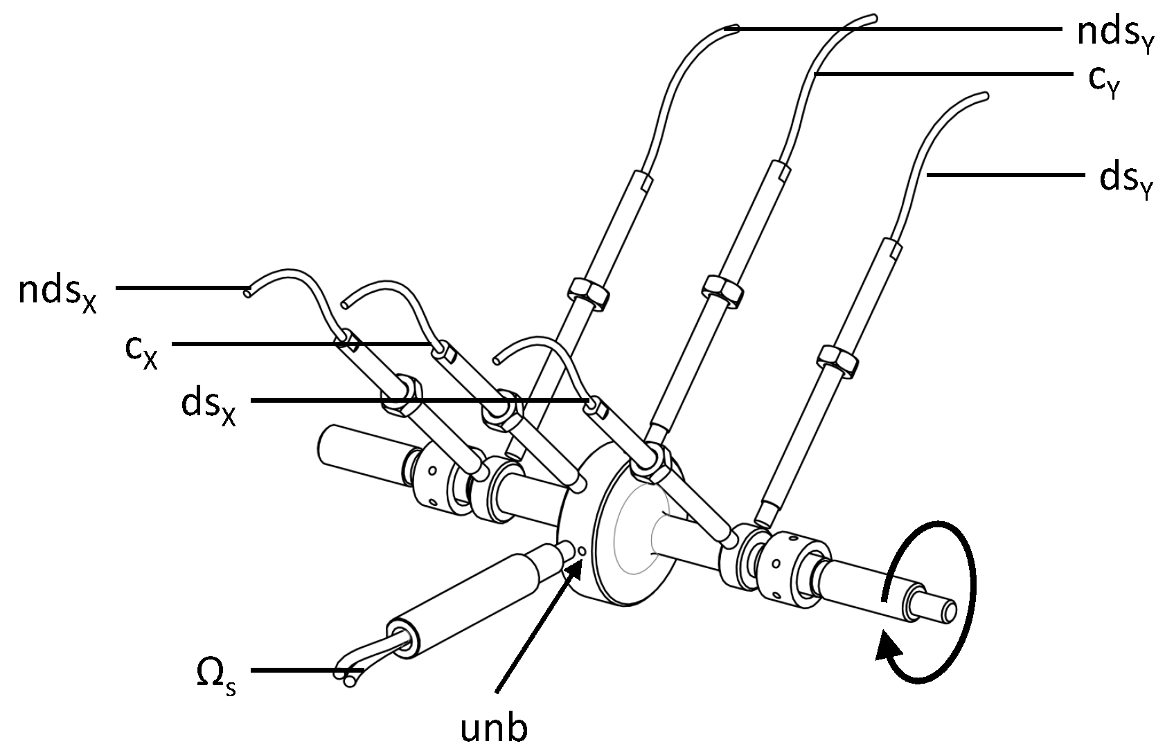
The Laval rotor, as depicted in Figure 1, was constructed from a solid piece of tool steel and is produced by lathing followed by precision grinding, resulting in a rotor with a concentricity error smaller than one micrometer over the entire rotor length. The main disk features four radial holes at ninety degrees circumferential spacing where grub screws can be inserted to set the amount of unbalance on the rotor (see Figure 3). Adjacent to each bearing surface, small disk features are present, which were necessary to minimize the cross-talk between the eddy current sensors for shaft orbit measurements, as shown in Figure 3. By hammer impact measurements, we determined the first two bending frequencies of the rotor—when suspended in compliant rubber bands—to be at 1601 Hz and 3925 Hz.

2.2. Sensor Configuration

The test setup contains sensors to measure rotor displacements, friction losses and oil temperatures. The temperatures of the oil in the inlet channel, of the bearing housing and of the oil just downstream of the bearings were measured by thermocouples. The dissipated friction losses in the bearings were found by substracting the internal losses of the motor from the total motor power, where the internal losses were measured by running the motor without the Laval rotor. The power necessary to accelerate the rotor, P acc = Ω s I rot Ω ˙ s , was also substracted from the total motor power.
The rotation speed of the shaft and the rings were measured by optical sensors. The displacements of the rotor were measured by eddy current displacement sensors with a resolution smaller than 0.1 micrometers and were sampled at a frequency of 51.2 kHz. Figure 3 shows the rotor with the displacement sensors and the shaft rotation speed sensor. We deliberately chose to measure the shaft displacement adjacent to the bearings instead of at the centerline of the bearings because we wanted to avoid distorting the cylindrical shape of the bearing bore by sensor protrusion. It is known that non-cylindrical features in floating ring bearings as small as a few micrometers already strongly affect the sub-synchronous behavior [16].

2.3. Lubrication System and Temperature Control

Oil was fed to the floating ring bearings at a controlled temperature and pressure. Since there is only a relatively small flow of oil through the bearings, bypass channels were included just upstream of the bearing housing to ensure that the oil is circulating thoroughly from the temperature-controlled oil sump to control the oil inlet temperature as well as possible. Temperature control was also applied to the bearing housing: it is constructed from aluminium and features strategically positioned chambers to allow temperature-controlled liquid to flow through. The bearing oil and the bearing housing liquids were kept in two separate circuits, so that combinations of warm oil in cold housing can be studied and vice versa. In this study, the temperatures of the bearing housing and the oil which is supplied to the bearings were always equal.

2.4. Oil

For all measurements in this study, multigrade automotive engine oil SAE 5W30 (Mobil 1 ESP Formula, Notre Dame de Gravenchon, France) was used. The friction losses due to the shearing of oil causes an increase in temperature in the bearings, so the viscosity will change. Furthermore, the shear rates in the bearing are considerable, so the oil behaves as a non-Newtonian, shear thinning fluid already at the minimum rotation speeds of 20 krpm. Therefore, the viscosity is also a function of shear rate γ ˙ . The following combination of the Vogel and the Cross equation is a suitable description of the oil viscsosity function in this case [17]:
μ oil ( T , γ ˙ ) = A oil e B oil ( T film + C oil ) r oil + 1 r oil 1 + ( K oil γ ˙ ) m oil .
The viscosity paremeters in Equation (1), as can be found in Table 2, were obtained by measurements of oil samples on a cone-on-plate viscometer. As the pressures in floating ring bearings are typically moderate [16], the pressure dependency of the viscosity can be neglected.

2.5. Measurement Sequence

For all run-ups, the rotor was accelerated from 20 to 180 krpm in 100 s at a constant acceleration rate. We ascertained that the rotordynamic response in 100 s is identical to the response in 1000 s, demonstrating that quasi-steady conditions can be assumed. Furthermore, we made sure that the rings were already rotating at the start of each measurement, as the rings tended to stick to the bearing housing at low rotation speeds. This was done by running the rotor to 50 krpm prior to starting each measurement and monitoring the bearing rotation speed.
It was observed that a run-up differs from a run-down: hysteresis occurs in the sub-synchronous response. This means that, in a run-up, the onset speed of a certain whirl is higher than the speed at which this whirl vanishes again during a run-down. This was also observed in the simulations of Tian [18] and the measurements of San Andres [13]. In this study, we present only run-up measurements.
Prior to the measurements, the rotor was balanced in situ to minimize the unbalance caused by mounting the coupling between the motor and the Laval rotor. The balancing was done in one plane, on the center disk of the rotor. In this study, the balanced condition is referred to as 0 mg·mm, although strictly speaking, some residual out-of-plane unbalance is present. The 0 mg·mm balanced condition was achieved by adjusting the grub screws by iteration until a minimum response over the operating range was observed.
The repeatability of the test setup was checked by repetitive measurements using the standard operating conditions. This was done throughout the measurement campaign, i.e., after performing various run-ups with different oil supply temperatures, rotor unbalance and oil supply pressures, the test setup was operated again at the standard operating condtions. For all measured values, these repetitive runs showed maximum deviations of less than two percent between runs, demonstrating the reliability of the measurement results. Furthermore, the temperature of the bearing housing was monitored during the measurements, showing fluctuations of maximum 3 K during a run-up. This relatively stable temperature is a result of the liquid cooling/heating channels in the aluminium bearing housing.

3. Results: Rotordynamic Response

In this section, the results of a run-up at standard operating conditions are extensively analyzed. Subsequently, the effects of varying the oil feed pressure, oil feed temperature and rotor unbalance are analyzed. Lastly, the effect of changing the bearing clearances is evaluated.

3.1. Rotordynamic Response at Standard Operating Conditions

The standard operating conditions were as follows:
  • The oil inlet pressure p i is set at 2 bar.
  • The oil inlet temperature T i is set at 310 K.
  • The bearing housing temperature T bh is set at 310 K .
  • The rotor unbalance is set at 100 mg·mm.
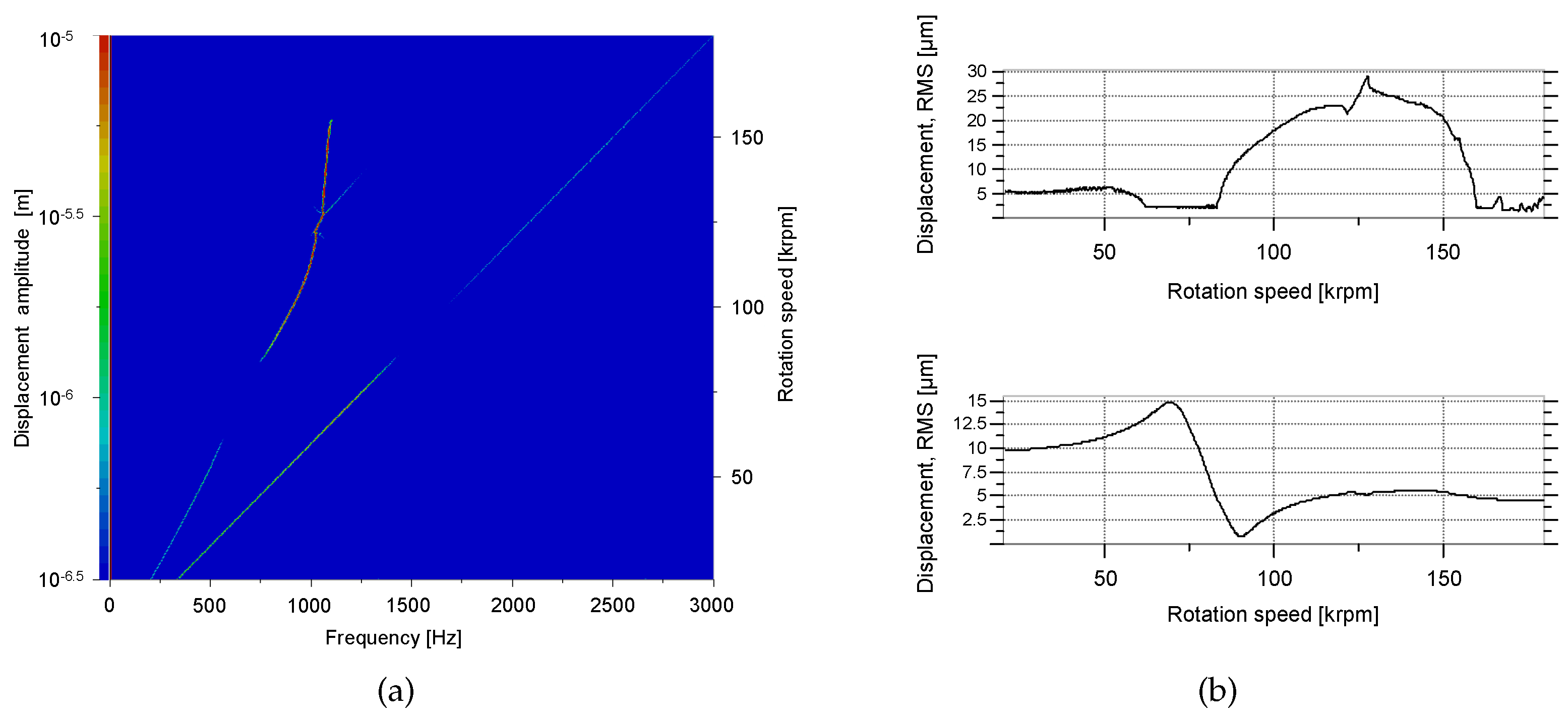
Under these conditions, the response depicted in Figure 4 has been measured. The waterfall plot shows the displacement of the center disk as a function of the rotation speed. When bandpass filters 0.05 Ω s 2 π < f < 0.95 Ω s 2 π and 0.95 Ω s 2 π < f < 1.05 Ω s 2 π are applied to this data, the sub-synchronous and synchronous content of the shaft displacement is found. Figure 4b gives the root mean square (RMS) value of the sub-synchronous and synchronous displacement of the disk as a function of the rotation speed.
During the run-up at standard operating conditions, the following phenomena have been observed:
  • From 20 to 62 krpm, some mild sub-synchronous oil whirl occured at a frequency of half the sum of the shaft speed and the ring speed: f = ( Ω s + Ω r ) 2 1 2 π . The ring speeds will be presented in Figure 7.
  • The synchronous response peaked at 68 krpm: the critical speed of this rotor-bearing system. After passing this critical speed, the synchronous response decayed again.
  • At 83 krpm, an oil whirl starts, this time at a frequency somewhat below f = ( Ω s + Ω r ) 2 1 2 π .
  • At 115 krpm, the oil whirl interfered with half of the shaft rotation speed and jumped to a frequency of f = Ω s 2 1 2 π .
  • At 130 krpm, the oil whirl locked into the first bending mode of the rotor-bearing system (which is the same mode that is triggered at 83 krpm by the synchronous excitation) and formed a whip.
  • At 158 krpm, the oil whip vanished.
By combining the data of all six displacement sensors, it is observed that the rotor always whirls in a forward, cylindrical mode: the whirl is in the same direction as the shaft rotation speed and the orbits of the three locations along the shaft are all in phase. Contrary to the typical response of a turbocharger [19] that has two overhung disks instead of one center disk, no conical modes were observed during the measurements. Figure 5 shows the orbits of the shaft measured at the locations presented in Figure 3.
Another aspect of interest of this study pertains to the bearing friction loss, which can be a significant part of the power losses in a turbocharger, particularly in low engine load conditions [20]. Figure 6 presents the friction losses of one bearing as a function of rotation speed, at standard operating conditions. In case the friction losses would be simply related to Couette flow, Petroff’s equation of the friction losses would be stated in the form of P friction Ω 2 μ oil [21]. Clearly, the response in Figure 6 does not increase quadratically with rotation speed, so the viscosity of the oil films appears to decrease significantly as the rotation speed increases. Hoepke [22] provides simple formulas that can be rewritten to identify the effective viscosity of the inner and the outer oil film based on the ring speed and the total power loss, which is out of the scope of the present study.
The friction losses, however, are not only a function of the Couette shear losses. As can be observed in Figure 6, the friction losses of the floating ring bearing also strongly depend on squeeze motion as reflected by the increase of friction losses at 83 krpm once the oil whirl occurs. The same conclusion was also drawn by Tian [23], who discovered by simulations that oil whirl significantly contributes to the friction losses of a floating ring bearing.
The rotation speeds of the rings of the floating ring bearings were measured by optical sensors perpendicular to the axis of the ring and are presented in Figure 7.
From the start at 20 krpm, the ring speed gradually increases as the shaft speed increases. At 83 krpm, the oil whirl starts (see Figure 4a) and the ring speed suddenly increases. At speeds above 115 krpm, the ring speed becomes constant. Trippett and Li [24] also observed this and reasoned that this is due to the increase of the temperature in the inner oil film, which has a smaller clearance and therefore greater friction losses than the outer fluid film [22]. As the inner oil film becomes warmer than the outer oil film, the drag torque from the inner oil film becomes lower and therefore the ring speed ratio ( Ω r / Ω s ) reduces. This, however, seems only part of the explanation. As the ring speed ratio quite abruptly becomes constant at the same moment that oil whirl occurs, it seems that the constant ring speed is imposed by the oil whip conditions. At speeds above 160 krpm, the oil whirl vanishes and, subsequently, the ring speed even decreases with increasing shaft speed. The ring speed profile of Figure 7 is similar to the profile measured by Köhl [25]. We found that the ring speed ratio mostly depends on the ratio of inner-to-outer bearing clearance; oil feed pressure and rotor unbalance have a relatively small influence on the ring speed ratio.

3.2. Response as a Function of Oil Feed Pressure

The feed pressure of the floating ring bearings was varied between 1 bar and 3 bar (see Figure 8). It is noteworthy that at feed pressures above 3 bar, the hydrostatic pressure prevented the ring from rotating at speeds below 50 krpm.
The synchronous amplitude at the center disk and at the bearings increase with feed pressure. Brouwer [26] performed shaft motion measurements on a turbocharger with floating ring bearings and found a similar relation. This relation is counter-intuitive, as an increase in feed pressure is expected to result in a higher bearing stiffness and therefore also a smaller response at the bearings. We currently have no plausible explanation for this interesting phenomenon.
The subsynchronous amplitude at the center disk also increases with increasing feed pressure, as shown in Figure 8b. Our understanding of this relation is as follows: the higher the feed pressure, the smaller the extent of the cavitated domain and thus the more unstable the bearing will be. Furthermore, the peak in the subsynchronous response, caused by the critical speed equalling the whirl frequency, increases with feed pressure because the critical speed increases with feed pressure, as depicted in Figure 8a.
Furthermore, an increase of feed pressure delays the onset speed of oil whirl, but eventually the amplitudes are higher at increased feed pressures and the oil whirl remains over a longer rotation speed range, as can be observed in Figure 8b and in the waterfall plots in Figure 9. Schweizer [19] also observed that an increase of pressure can delay the onset speed of oil whirl.
We observed that the friction losses of the floating ring bearing increase with an increase of oil feed pressure, depicted in Figure 10. As can be observed in the waterfall plots in Figure 9, this is partly due to oil whirl: at high oil feed pressure, oil whirl occurs more severely over a wide operating range, resulting in an increase of friction losses as more energy is dissipated due to the oil whirl motion. Furthermore, at higher oil feed pressures, a smaller fraction of the films is cavitated and, conversely, a larger fraction is full film. As the friction losses originate from the full film areas, the total friction losses increase. Lastly, an increase in oil feed pressure also increases the oil flow rate through the bearing and, therefore, more heat is carried away from the bearing, which, in turn, results in a higher average viscosity in the bearing, and thus more friction losses [27].
Deligant [27] obtained similar results in his measurements: a 10% increase of friction losses over a 2 bar pressure increase. Deligant, however, did not relate this explicitly to the oil whirl but instead related it to cooler oil films due to the increased oil flow at higher feed pressures.

3.3. Response as a Function of Oil Feed Temperature

An increase of oil feed temperature generally leads to a decrease of rotor displacement amplitude, as can be observed in Figure 11. This is in contradiction to the measurements of Brouwer [26], who observed that the displacement amplitudes of the rotor are generally largest at high oil feed temperatures. This shows that different rotor-bearing geometries will react differently to an increase of oil feed temperature.
The onset speed of oil whirl is slightly increased by increasing the temperature as depicted in Figure 11b. We observed that the ring speeds are generally higher in case the oil feed temperature increases, as was also measured by Porzig [9]. We expect that an increase in oil feed temperature causes the temperature and thus the viscosity of the outer oil film to be closer to the temperature of the inner oil film. The temperature of the bearing housing is the same as the temperature of the oil supply channel so increasing this temperature directly affects the outer fluid film viscosity.
As can be seen in Figure 12, the friction losses decrease by increasing the oil feed temperature. However, the reduction is typically only 10% to 20%, which is considerably less than the reduction of the oil feed viscosity, which is more than 50% in the case of increasing the oil temperature from 298 to 332 K. Similar results were also measured by Deligant [27], who observed a 10% to 20% decrease in friction losses at an oil feed temperature increase of 20 K. It is considered that friction heating causes the temperature of the inner film to be considerably higher than the oil feed temperature at low oil feed temperatures, which reduces the difference between friction losses at low and high oil feed temperatures.

3.4. Response as a Function of Rotor Unbalance

As can be expected, adding unbalance to the rotor will increase the synchronous amplitude at the critical speed, as can be seen in Figure 13a. Moreover, we observed that rotor unbalance can suppress the onset speed of whirl, but can also cause it to remain in an oil whirl over a larger speed range, as depicted in Figure 13b.
As the rotor with a high unbalance level remains in an oil whirl at speeds above 140 krpm, its friction losses are also larger in this range, as can be seen in Figure 14. For the rest of the speed range, the unbalance amount does not significantly affect the friction losses.

3.5. Response as a Function of Bearing Clearances

Three sets of bearing clearances have been evaluated, as can be seen in Table 3. It should be noted that these bearings have clearances which were especially chosen for these measurements and as such, are not strictly representative for bearings found in commercially available turbochargers. The bearing clearances were measured before and after testing.
Figure 15 and Figure 16 demonstrate that the sub-synchronous response generally increases with increasing the clearances. The opposite is observed for the synchronous response, which decreases with increasing bearing clearances. The same trend was also observed for the case of a plain journal bearing [28]. The larger bearing clearance allows for more energy to be dissipated by squeeze motion in the bearing and thus results in a lower amplitude at the center disk in the critical speed range.
Remarkably, almost no differences have been observed between the friction losses of the three different bearing configurations. Although Bearing 1 has clearances which are 1.5 to 2 times smaller than those of Bearing 3, the differences in friction losses are typically no more than 10%, as can be seen in Figure 17. According to the simple Petroff equation, the friction power should be inversely proportional to the clearance C: P friction Ω 2 μ oil Ω 2 μ oil C C . If we assume that the minimum film thickness depends on the rotor (unbalance) load, and as this load is constant between the different bearings, we can assume that the minimal film height is independent of the bearing clearance. At high eccentricities, the minimal film height largely determines the friction losses [21]; therefore, the friction losses are similar for different clearances.

4. Conclusions

This study presents experimental results of the dynamic behavior and the friction losses of a Laval rotor supported by floating ring bearings. The interaction of the flexible shaft with the floating ring bearings causes sub-synchronous oil whirl, which locks into an oil whip and eventually vanishes again. We observed that friction losses do not depend quadratically on the rotation speed, but instead appear to be highly dependent on the whirling amplitudes. The ring rotation speed remains constant in the range where severe oil whirl/whip occurs, which indicates that the ring speed in this condition is a consequence of the oil whip conditions rather than a cause. Furthermore, the influence of oil feed pressure, oil feed temperature, rotor unbalance and bearing clearances have been studied. Most phenomena observed in the measurements have been explained; however, the increased amplitude at an increase of oil feed pressure is still not fully understood.
The measurement data presented here showed good repeatability under well controlled thermal and unbalance conditions and can serve to validate numerical models that predict the rotordynamic behavior of turbocharger rotors supported by floating ring bearings. As a next step, adding a heat source to the currently presented test setup can bring insight into the effect of shaft temperature as the shaft temperatures in turbochargers are known to vary considerably.

Author Contributions

Rob Eling and Mathys te Wierik constructed the test setup and performed the experiments. Mathys te Wierik designed the test setup. Rob Eling analyzed the data and wrote the paper. Ron van Ostayen and Daniel Rixen added useful information and discussions relevant for this study.

Conflicts of Interest

The authors declare no conflict of interest.

References

  1. Schweizer, B. Total instability of turbocharger rotors—Physical explanation of the dynamic failure of rotors with full-floating ring bearings. J. Sound Vib. 2009, 328, 156–190. [Google Scholar] [CrossRef]
  2. Shaw, M.C., Jr.; Nussdorfer, T.J., Jr. An Analysis of the Full-Floating Journal Bearing; National Advisory Committee for Aeronautics: Washington, DC, USA, 1947; Volume 866. [Google Scholar]
  3. Nguyen-Schäfer, H. Rotordynamics of Automotive Turbochargers; Springer: Berlin/Heidelberg, Germany, 2012. [Google Scholar]
  4. San Andres, L.; Rivadeneira, J.C.; Gjika, K.; Groves, C.; LaRue, G. Rotordynamics of Small Turbochargers Supported on Floating Ring Bearings—Highlights in Bearing Analysis and Experimental Validation. J. Tribol. 2007, 129, 391. [Google Scholar] [CrossRef]
  5. Vetter, D.; Hagemann, T.; Schwarze, H. Predictions for run-up procedures of automotive turbochargers with full-floating ring bearings including thermal effects and different bearing setups. Tribol. Trans. 2014, 375–386. [Google Scholar] [CrossRef]
  6. Daniel, C.; Woschke, E.; Nitzschke, S.; Strackeljan, J.; Driot, N.; Braun, K.l.; Koutsovasilis, P. Validierung der Hochlaufsimulation für automotive Abgasturbolader. In Proceedings of the Internationale Tagung Schwingungen in Rotierenden Maschinen (SIRM2015–11), Magdeburg, Germany, 23–25 February 2015; pp. 1–9.
  7. Li, S.; Tuzcu, S.; Klaus, M.; Rienäcker, P.A.; Schwarze, P.H. Analyse der Einflüsse der hydrodynamischen Axiallagerung auf das rotordynamische Verhalten eines PKW-Abgasturboladers. In Proceedings of the Internationale Tagung Schwingungen in Rotierenden Maschinen (SIRM2015–11), Magdeburg, Germany, 23–25 February 2015; pp. 1–10.
  8. Tian, L.; Wang, W.J.; Peng, Z.J. Nonlinear effects of unbalance in the rotor-floating ring bearing system of turbochargers. Mech. Syst. Signal Process. 2013, 34, 298–320. [Google Scholar] [CrossRef]
  9. Porzig, D.; Raetz, H.; Schwarze, H.; Seume, J.R. Thermal analysis of small high-speed floating-ring journal bearings. In Proceedings of the 11th International Conference on Turbochargers and Turbocharging, London, UK, 13–14 May 2014; pp. 421–436.
  10. San Andres, L.; Barbarie, V.; Bhattacharya, A.; Gjika, K. On the Effect of Thermal Energy Transport to the Performance of (Semi) Floating Ring Bearing Systems for Automotive Turbochargers. J. Eng. Gas Turbines Power 2012, 134, 102507. [Google Scholar] [CrossRef]
  11. San Andres, L.; Maruyama, A.; Gjika, K.; Xia, S. Turbocharger Nonlinear Response With Engine-Induced Excitations: Predictions and Test Data. J. Eng. Gas Turbines Power 2010, 132, 032502. [Google Scholar] [CrossRef]
  12. Nguyen-Schäfer, H. Nonlinear Rotordynamic Computations of Automotive Turbochargers Using Rotating Floating Ring Bearings at High Rotor Speeds. In Proceedings of the 10th SIRM International Conference, Berlin, Germany, 25–27 February 2013; pp. 1–10.
  13. San Andres, L.; Vistamehr, A. Nonlinear rotordynamics of vehicle turbochargers: parameters affecting sub harmonic whirl frequencies and their jump. In Proceedings of the 8th IFToMM International Conference on Rotor Dynamics, Seoul, Korea, 12–15 September 2010; pp. 1077–1086.
  14. Alsaeed, A.A.; Kirk, R.G.; Bashmal, S. Effects of radial aerodynamic forces on rotor-bearing dynamics of high-speed turbochargers. Proc. Inst. Mech. Eng. C 2014, 228, 2503–2519. [Google Scholar] [CrossRef]
  15. Ying, G.; Meng, G.; Jing, J. Turbocharger rotor dynamics with foundation excitation. Arch. Appl. Mech. 2008, 79, 287–299. [Google Scholar] [CrossRef]
  16. Eling, R.; van Ostayen, R.; Rixen, D. Multilobe Floating Ring Bearings for Automotive Turbochargers. In Proceedings of the 9th IFToMM International Conference on Rotor Dynamics, Cham, Switzerland, 26 May 2015.
  17. Knauder, C.; Allmaier, H.; Sander, D.E.; Salhofer, S.; Reich, F.M.; Sams, T. Analysis of the Journal Bearing Friction Losses in a Heavy-Duty Diesel Engine. Lubricants 2015, 3, 142–154. [Google Scholar] [CrossRef]
  18. Tian, L.; Wang, W.J.; Peng, Z.J. Effects of bearing outer clearance on the dynamic behaviours of the full floating ring bearing supported turbocharger rotor. Mech. Syst. Signal Process. 2012, 31, 155–175. [Google Scholar] [CrossRef]
  19. Schweizer, B.; Sievert, M. Nonlinear oscillations of automotive turbocharger turbines. J. Sound Vib. 2009, 321, 955–975. [Google Scholar] [CrossRef]
  20. Serrano, J.R.; Olmeda, P.; Tiseira, A.; García-Cuevas, L.M.; Lefebvre, A. Theoretical and experimental study of mechanical losses in automotive turbochargers. Energy 2013, 55, 888–898. [Google Scholar] [CrossRef]
  21. Stachowiak, G.; Batchelor, A.W. Engineering Tribology, 4th ed.; Butterworth-Heinemann: Oxford, UK, 2014. [Google Scholar]
  22. Hoepke, B.; Uhlmann, T.; Pischinger, S.; Lueddecke, B.; Filsinger, D. Analysis of Thrust Bearing Impact on Friction Losses in Automotive Turbochargers. J. Eng. Gas Turbines Power 2015, 137, 82507. [Google Scholar] [CrossRef]
  23. Tian, L.; Wakelin, M.; Lancaster, C.; Lindsay, M. The Effect of Oil Film Instability on Power Losses Prediction of a Turbocharger Rotor-Fully Floating Ring Bearing System; Cummins Turbo Technologies: Huddersfield, UK, 2016. [Google Scholar]
  24. Trippett, R.J.; Li, D.F. High-speed Floating-Ring Bearing Test and Analysis. ASLE Trans. 1984, 27, 73–81. [Google Scholar] [CrossRef]
  25. Köhl, W.; Kreschel, M.; Filsinger, D. Modellabgleich eines Turboladerrotors in Schwimmbuchsenlagerung anhand gemessener Schwimmbuchsendrehzahlen. In Proceedings of the Internationale Tagung Schwingungen in Rotierenden Maschinen (SIRM2015–11), Magdeburg, Germany, 23–25 February 2015; Volume 5, pp. 1–10.
  26. Brouwer, M.D.; Sadeghi, F.; Lancaster, C.; Archer, J.; Donaldson, J. Whirl and Friction Characteristics of High Speed Floating Ring and Ball Bearing Turbochargers. J. Tribol. 2013, 135, 041102. [Google Scholar] [CrossRef]
  27. Deligant, M.; Podevin, P.; Descombes, G. Experimental identification of turbocharger mechanical friction losses. Energy 2012, 39, 388–394. [Google Scholar] [CrossRef]
  28. Bonneau, O.; Arghir, M.; Jolly, P. Dynamic control of a flexible shaft mounted in adaptive or active bearing. J. Mech. Eng. Autom. 2014, 4, 1–7. [Google Scholar]
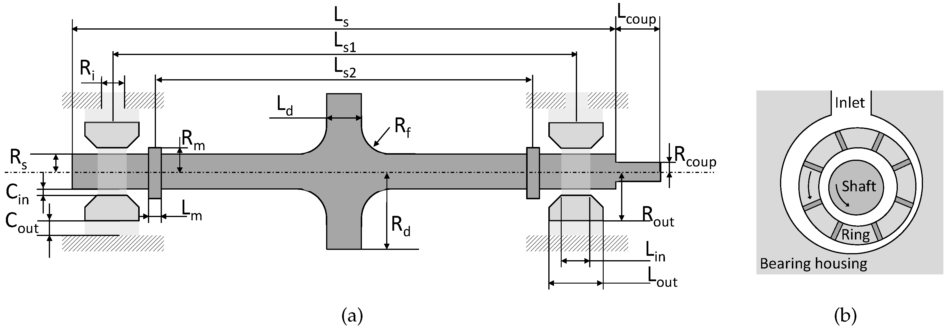
Figure 1. Laval rotor (a) and schematic representation of a floating ring bearing (b).
Lubricants 05 00007 g001
Figure 2. Schematic overview of the experimental setup. Table 1 provides descriptions of the numbered items.
Lubricants 05 00007 g002
Figure 3. Rotor with a rotation speed sensor ( Ω s ) and six orthogonally placed displacement sensors. ds, nds and c denote drive, non-drive side, and center, respectively. Unbalance can be configured by inserting grub screws in the threaded hole indicated by unb.
Lubricants 05 00007 g003
Figure 4. Displacement amplitude of the center disk under standard operating conditions ( P in = 2 bar, T in = 310 K, unb = 100 mg·mm): Waterfall plot (a) and synchronous (below) and sub-synchronous (above) intensities expressed in RMS values of the band-pass filtered amplitudes (b).
Lubricants 05 00007 g004
Figure 5. Rotor orbits at (a) 90 krpm and (b) 120 krpm.
Lubricants 05 00007 g005
Figure 6. Friction losses of one floating ring bearing as a function of the shaft rotation speed under standard operating conditions ( P in = 2 bar, T in = 310 K, unb = 100 mg·mm). The friction losses of both bearings were measured by substracting the internal motor losses from the total power delivered by the motor.
Lubricants 05 00007 g006
Figure 7. Ring rotation speed and ring speed ratio Ω r / Ω s under standard operating conditions.
Lubricants 05 00007 g007
Figure 8. Influence of oil feed pressure on the rotordynamic response. (a) Synchronous response; (b) Sub-synchronous response.
Lubricants 05 00007 g008
Figure 9. Influence of oil feed pressure on the rotordynamic response. (a) Oil supply pressure P in = 1 bar; (b) P in = 2 bar; (c) P in = 3 bar; T in = 310 K, unb = 100 mg·mm.
Lubricants 05 00007 g009
Figure 10. Friction losses of a floating ring bearing as a function of oil feed pressure; T in = 310 K, unb = 100 mg·mm.
Lubricants 05 00007 g010
Figure 11. Influence of oil feed temperature on the rotordynamic response. (a) Synchronous response; (b) Sub-synchronous response.
Lubricants 05 00007 g011
Figure 12. Friction losses of a floating ring bearing as a function of oil feed temperature; P in = 2 bar, unb = 100 mg·mm.
Lubricants 05 00007 g012
Figure 13. Influence of rotor unbalance on the rotordynamic response. Synchronous response (a) and Sub-synchronous response (b) of the center disk as a function of rotor unbalance.
Lubricants 05 00007 g013
Figure 14. Friction losses of a floating ring bearing as a function of rotor unbalance. P in = 2 bar, T in = 310 K.
Lubricants 05 00007 g014
Figure 15. Influence of bearing clearances on the rotordynamic response, P in = 2 bar, T in = 310 K, unb = 100 mg·mm. (a) Bearing clearance configuration 1; (b) Bearing clearance configuration 2; (c) Bearing clearance configuration 3.
Lubricants 05 00007 g015
Figure 16. Influence of rotor unbalance on the rotordynamic response. (a) Synchronous response; (b) Sub-synchronous response.
Lubricants 05 00007 g016
Figure 17. Friction losses of a floating ring bearing with various clearance combinations, as indicated in Table 3; P in = 2 bar, T in = 332 K, unb = 250 mg·mm.
Lubricants 05 00007 g017
Table 1. Descriptions for the parts labeled with encircled numbers in Figure 2.
NumberDescriptionNumberDescription
1Bearing housing8Liquid cooling/heating drain
2Motor9Motor cooling supply
3Motor support bracket10Motor cooling drain
4Baseplate11Shaft displacement sensor
5Oil supply line12Thermocouple
6Oil drain line13Optical sensor
7Liquid cooling/heating supply
Table 2. Parameters for the Laval rotor supported by floating ring bearings.
Rotor ParametersRing Parameters
NameValueUnitDescriptionNameValueUnitDescription
R s 3.75mmRadius of shaft C in 8.5 μ mInner clearance
R d 15mmRadius of center disk C out 30 μ mOuter clearance
R m 6mmRadius measurement disk L in 5mmLength inner film
R f 5mmRadius of fillet L out 8mmLength outer film
L s 137mmShaft length R out 6.465mmOuter ring radius
L d 9mmLength of center disk I ring 1.5 × 10 7 kg· m 2 Ring rotation inertia
L m 5mmLength measurement disk ρ ring 8750kg· m 3 Material density
C T s 1.2 × 10 5 K 1 Coeff. thermal expansion E ring 110GPaMaterial E-modulus
L s 1 80mmLength of bearing span m ring 5.39gRing mass
L s 2 58mmMeasurement disk span C T r 1.4 × 10 5 K 1 Coeff. th. expansion
L coup 8mmLength of coupling sectionOil Parameters
R coup 2.25mmRadius of coupling section ρ oil 855kg· m 3 Oil density
ρ s 7700kg· m 3 Material density c poil 2.1kJ/kg·KHeat capacity
E s 210GPaMaterial E-modulus k oil 0.145W/m·KThermal conductance
I rot 9.2 × 10 6 kg· m 2 Rotor rotation inertia A oil 0.44mPa·sTemperature coeff.
m rot 101gRotor mass B oil 633°CTemperature coeff.
C oil 88.6°CTemperature coeff.
r oil 0.5-Shear rate coefficient
m oil 0.8-Shear rate coefficient
K oil 7.2 × 10 7 s 1 Shear rate coefficient
Table 3. Bearing clearances evaluated in this study.
Inner Clearance ( μ m)Outer Clearance ( μ m)
Bearing clearance configuration 18.530
Bearing clearance configuration 21335
Bearing clearance configuration 316.541