Article

Tribo-Mechanisms of Carbon Nanotubes: Friction and Wear Behavior of CNT-Reinforced Nickel Matrix Composites and CNT-Coated Bulk Nickel

by
Leander Reinert
1,
Sebastian Suárez
1 and
Andreas Rosenkranz
1,2,*
1
Department of Material Science and Engineering, Saarland University, Saarbrücken 66123, Germany
2
Institute of Experimental Physics, Pontificia Universidad Católica de Chile, Santiago 7820436, Chile
*
Author to whom correspondence should be addressed.
Lubricants 2016, 4(2), 11; https://doi.org/10.3390/lubricants4020011
Submission received: 1 March 2016 / Revised: 6 April 2016 / Accepted: 14 April 2016 / Published: 19 April 2016
(This article belongs to the Special Issue Tribofilms and Solid Lubrication)

Abstract

:
In this study, nickel matrix composites reinforced by carbon nanotubes (CNTs) are compared to unreinforced CNT-coated (by drop-casting) bulk nickel samples in terms of their friction and wear behavior, thus gaining significant knowledge regarding the tribological influence of CNTs and the underlying tribo-mechanism. It has been shown that the frictional behavior is mainly influenced by the CNTs present in the contact zone, as just minor differences in the coefficient of friction between the examined samples can be observed during run-in. Consequently, the known effect of a refined microstructure, thus leading to an increased hardness of the CNT reinforced samples, seems to play a minor role in friction reduction compared to the solid lubrication effect induced by the CNTs. Additionally, a continuous supply of CNTs to the tribo-contact can be considered isolated for the reinforced composites, which provides a long-term friction reduction compared to the CNT-coated sample. Finally, it can be stated that CNTs can withstand the accumulated stress retaining to some extent their structural state for the given strain. A comprehensive study performed by complementary analytical methods is employed, including Raman spectroscopy and scanning electron microscopy to understand the involved friction and wear mechanisms.

1. Introduction

In recent years, carbon nanotubes (CNTs) have been receiving a lot of attention in the research community due to their outstanding intrinsic physical properties, particularly mechanical [1] and thermal [2]. In addition to that, their shape, high aspect ratio and high flexibility rendered them as a promising candidate for solid lubrication or as a lubricant additive in tribological applications. Several studies have proved the ability of CNTs to reduce friction and wear; for example, when used as the reinforcement phase in composites [3,4,5,6,7,8,9], as a protective film [10,11,12,13], solid lubricant [8,9,10,12,14,15], or lubricant additive [16,17,18,19]. Although all of these systems show improvements to a different extent, the tribo-mechanisms inducing these effects are clearly differing and not completely understood. The variation in testing parameters and tribological systems used make it rather difficult to correlate the measured effect to the underlying friction and/or wear mechanism. Therefore, the aim of the present work is to study the behavior of CNTs used as reinforcement phase or as a protective film, but keeping all the tribological testing parameters fairly constant. Thus, differences in the tribological behavior can be traced back more easily as a function of the purpose of use.
The main drawback of CNTs is their processing difficulty due to strong van der Waals interactions that generate agglomerates. This reduces all of the aforementioned properties, as well as the integration as a second phase; for example, in composites [20]. One method for facile de-agglomeration of CNTs is the dispersion in solvents. The CNTs can be dispersed with [21,22,23,24,25] or without prior functionalization [26,27]. As a functionalization (covalently or non-covalently) changes the chemical composition and/or physical properties of the CNTs, this should be avoided if effects of CNTs on an experiment need to be considered in isolation [21,22,23,24,25]. Therefore, for the present research work, we resigned on functionalizing the CNTs. Based upon our experience in previous studies, ethylene glycol is chosen as the solvent due to its low toxicity and good dispersion results for CNTs [26,28,29]. Furthermore, polyols like ethylene glycol allow for a subsequent functionalization of CNTs or the deposition of metal particles onto their surface, establishing the possibility of further research work on this topic [28].
In order to study the tribological behavior of CNTs, it seems to be reasonable to start with experiments under dry conditions to avoid the influence of a lubricant such as oil or grease. Thus, there are two main possibilities: (1) the study of a CNT-film deposited on a surface; or (2) the investigation of a composite material. Regarding CNT-films on top of surfaces, friction- and wear-reducing effects are often correlated to the ability of CNTs to roll and, thus, separating the rubbing surfaces. In this context, the CNTs can act as ball bearings [5,9,30,31]. For example, Dickrell et al. [31] were able to prove differences in the frictional behavior of CNTs as a function of their orientation on top of a surface. Often, the friction reduction of CNTs is also explained by their degradation, thus forming a lubricating graphitic tribolayer [5,8,9,11]. In this case, simulations estimate a contact pressure between 1.5 to 2.5 GPa to deteriorate the CNTs [32].
When it comes to reinforced composites, several influences on friction and wear have to be added to the discussion. There are three groups of composite materials that have to be distinguished first. Polymer-matrix composites are mainly used in applications where light weight is desired, but no heat resistance is needed. Oppositely, ceramic matrices are used where inertness under high temperatures, as well as high mechanical properties, are required. Finally, metal matrix composites (MMC) lie between both application fields, presenting an intermediate research field that offers high ductility, high electrical conductivity, as well as good heat resistivity. Therefore, MMCs are selected in this work for the composite material. In the case of MMCs, besides the mentioned effects of CNTs, wear reduction is often referred to as a hindered plastic deformation of the material due to the restricted movement of dislocations induced by the presence of CNTs [30]. Furthermore, reduced wear can be correlated to the grain refinement effect, thus inducing an increased hardness (Hall-Petch relation) [29]. Furthermore, it is important to mention that not only changes in the microstructure affect the tribological properties, but also the formation of interphases between CNTs and matrix material needs to be considered. In the literature, it is controversially discussed if there is a formation of interphases in a CNT-reinforced metal matrix composite, or rather when using which metal matrix [33]. When using nickel as the matrix material, no chemical reaction between Ni and CNTs can be observed [34,35]. Furthermore, nickel forms only metastable carbides under very specific conditions, therefore being suitable for a reinforcement based on CNTs with the parasitic emergence of interphases [36,37]. Consequently, nickel is chosen as the matrix material in the present study.

2. Results and Discussion

2.1. Frictional Behavior

The different sample sets were first compared in terms of the temporal evolution of the coefficient of friction (COF) using a ball-on-disk tribometer under linear reciprocating motion and an Al2O3 ball as counter body. In Figure 1 the COF is plotted as a function of the number of sliding cycles (total sliding cycles of 200) for the sintered Ni reference, the CNT-coated sample and the CNT-reinforced sample.
The COF of the Ni reference increases during the first 60 cycles from 0.2 to roughly 0.45. In the beginning of the experiment, only some single asperities of the ball and the substrate are in contact with each other, thus generating a small contact area. With time (increasing number of sliding cycles), the initial surface roughness is worn off and the indentation depth of the asperities increases which leads to an enlargement of the contact area. This is directly related to the increase in the COF as observed in Figure 1. Moreover, as Raman spectroscopy can show later in this work, the formation of an oxide layer contributes to the increasing COF, since Ni oxide is known to act as a high-shear strength layer [5]. Afterwards, the COF drops slightly down within the next 90 cycles to a value of 0.36 remaining stable for the rest of the measuring time. After a certain time, the substrate and the counter body undergo a transition from non-conformal to conformal contact conditions due to the smoothing of the surface roughness which results in a reduced COF. The behavior is typical for pure metals and has been already extensively investigated [38].
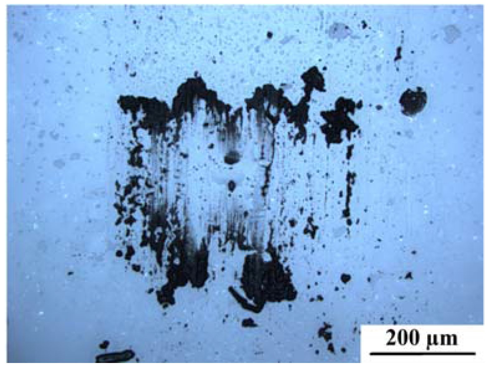
In case of the CNT-coated sample, the COF drops down within the first 50 cycles from 0.38 to 0.1, remaining stable at this value for the rest of the measurement. The high initial COF may be explained by shifting large amounts of entangled CNTs to the sides of the wear track within the first sliding cycles. The shifting and stacking of entangled CNTs requires a higher transversal force, thus resulting in a higher COF. Subsequently, the wear track can be continuously supplied with small amounts of CNTs that are transferred from the end of the wear tracks back to the contact area. In addition to that, entangled CNTs are also transferred to the ball, which can be seen in Figure 2. These transferred CNTs will also contribute to the continuous supply of CNTs to the contact area. In this case, the CNTs act as solid lubricant as there is no other difference to the nickel reference than the CNTs in the contact area [5,10,12,14,15]. Furthermore, it is noteworthy that no oxide formation is detected in this case.
Regarding the CNT-reinforced sample, the COF remains stable and at a low value of around 0.1 over the entire measuring time. Using the Hertzian contact model, the contact pressure for the given material pairing (Al2O3 against Ni) can be estimated to 1.56 GPa [29]. This value greatly exceeds the yield strength of the samples, which is 0.3 for pure Ni and 0.45 GPa for the CNT-reinforced Ni. Thus, a greater penetration depth and a subsequently increased real contact area is resulting for the Ni reference [29]. Additionally, a very similar COF can be noticed after the first 50 sliding cycles for the CNT-reinforced sample compared to the CNT-coated sample. This might be a consequence of the embedded CNT clusters that can act as a lubricant reservoir, supplying the rubbing surfaces continuously with CNTs [5]. As the COF of both samples is nearly identical, it is reasonable to assume that this behavior is mainly induced by CNTs present in the contact zones.
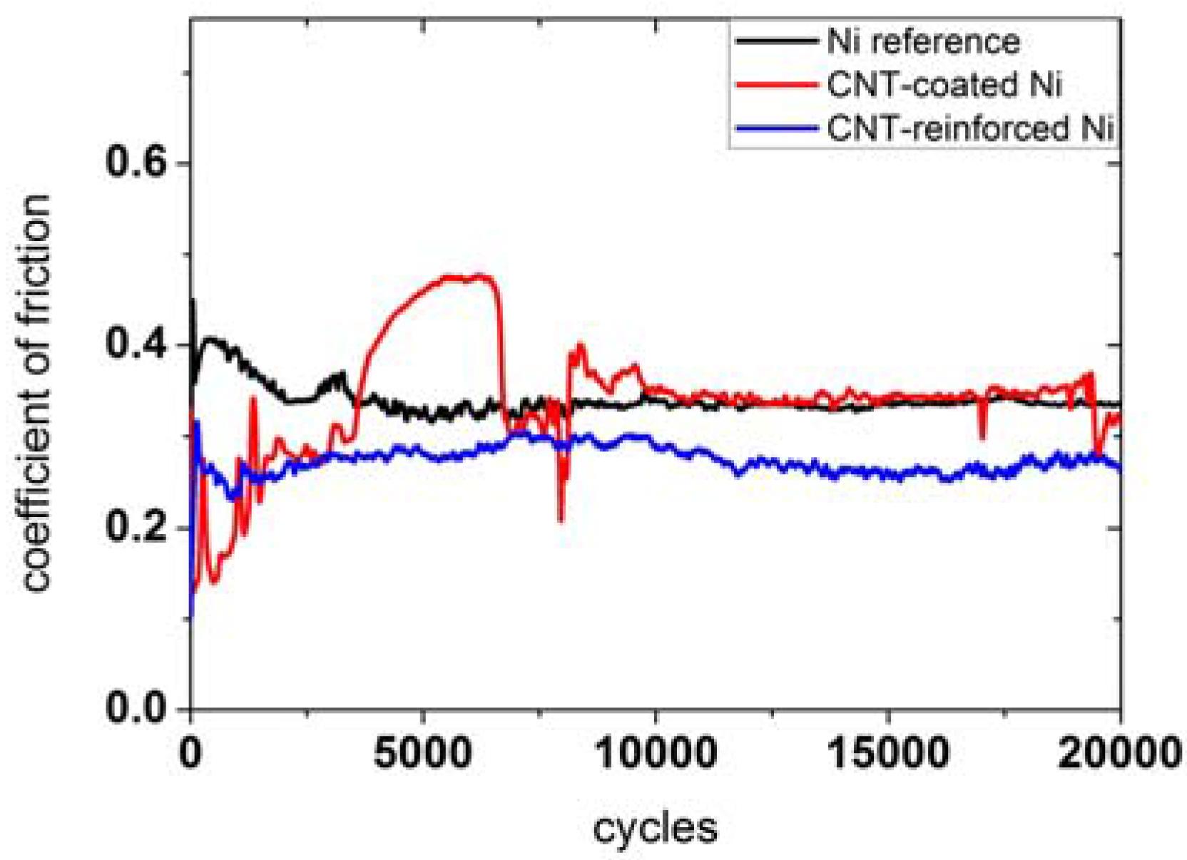
This being stated, it is of interest to examine the long-term behavior of these samples. In Figure 3 the temporal evolution of the COF of the three samples for 20,000 sliding cycles is depicted.
For the Ni reference, it can be observed that the COF decreases within the first 2500 cycles from 0.4 to 0.35, henceforward remaining fairly constant. With time, the surface asperities are worn off, thus generating conformal contact conditions. This process ends after the first 2500 cycles, reaching an equilibrium and, thus, steady state conditions [38]. As could also be detected for the 200 sliding cycles, Ni oxide is formed during the run-in. As a consequence, the final COF is mainly influenced by this oxide layer. The steady-state COF is also in good agreement with those values reported in the literature for microcrystalline Ni rubbed against Al2O3 [39].
In the case of CNT-coated Ni, it becomes clear that the COF is just reduced within the first 3000 cycles. During this time interval, the COF increases from 0.1 to 0.35 and also shows some sharp spikes. These spikes can be explained with the removal of the CNT layer. It is worth mentioning that this removal is just temporary because CNTs that have been shifted out of the wear track can be partially transferred back during the sliding movement. In between 3000 and 7000 sliding cycles, the COF increases from 0.35 to 0.47. This might be a consequence of several influences which act at the same time. On the one hand, this increase might be attributed to the occurrence of the ongoing direct contact of the Al2O3 ball with the Ni substrate (increasing contact area), thus showing a similar behavior as the reference within the first 1000 cycles. Furthermore, the generation of oxide particles contributes to the increasing COF as discussed for the reference. Finally, the CNTs are not acting as a lubricant anymore, as they are completely shifted out of the wear track. However, carbon can still be found in the middle of the wear track as shown by Raman spectroscopy and discussed later in this work. It is rather unclear, how the observed carbon configuration affects the COF. This topic is subject of ongoing research work and will be addressed in a follow-up paper. During the next 3000 cycles, the contacting surfaces undergo a transition from non-conformal to conformal contact conditions. Additionally, several spikes can be noticed which might be caused by a temporary appearance of “fresh” CNTs that have been transferred back again from the sides of the wear track to the contact zone. The observed spikes that show a higher COF can result from the generation of wear particle accumulations. After 10,000 cycles, the CNT-layer is completely removed and the COF remains stable for the rest of the measurement, as observed for the reference. This can be explained with the presence of an oxide layer and the complete absence of CNTs.
The CNT-reinforced sample shows a rather different behavior. For this sample, the COF increases from 0.1 to 0.3 within the first 500 cycles. During the next 1000 cycles, the COF decreases again to a value of 0.25. For the remaining testing time, the COF fluctuates between 0.25 and 0.3. The first increase can be explained by the increasing contact area, as asperities of the ball and the substrate are worn off with time and the surface is slightly indented by the counter body. Afterwards, the decrease of COF seems to be a consequence of CNTs that reach the contact area as they are released from the agglomerate clusters inside the nickel matrix due to wear. The fluctuation in the third part might be explained by the limited amount of CNTs that can be transferred to the contact area. In other words, while the surface is worn off, new CNTs will be continuously shifted to the contact area, thus supplying the contact zone with new solid lubricant. However, it is worth mentioning that the amount of CNTs transferred to the contact zone will differ with time due to the slightly inhomogeneous distribution of CNT clusters in the bulk material. Another reason for a fluctuation of the COF might be the mild and very irregular formation of oxides within the wear track. This can be explained by a partial protection against oxidation induced by the irregular presence of CNTs, as carbon can act as an oxygen diffusion barrier. This is because of the higher stability of carbon oxide compared to Ni oxide, which can be seen in the corresponding Ellingham diagram.

2.2. Wear Behavior

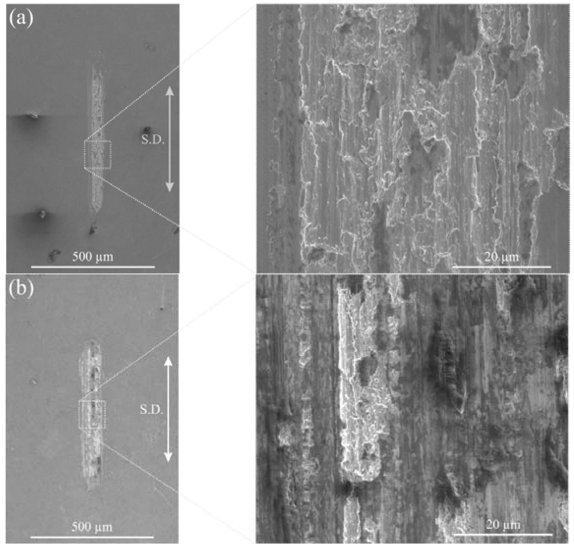
In general, it can be pointed out that different wear mechanisms are normally acting simultaneously during a tribological experiment. Therefore, only the dominating mechanisms are named and discussed in the following section. In Figure 4, SEM micrographs of the wear tracks observed on the Ni reference after 200 (a) and 20,000 sliding cycles (b) are depicted.
It can be stated that the main wear mechanism for both wear tracks is plowing. This is evident as the hardness of the counter body (Al2O3 ball) greatly exceeds the hardness of the nickel reference. Furthermore, the formation of Ni oxide particles can additionally add an abrasive component. Particularly for NiO, it has also been proven that it acts as a high shear strength layer which increases the COF [5]. Together with the increasing contact area during the run-in process, this leads to an enlarged COF. The oxide formation was studied by Raman spectroscopy and will be further discussed in the next section of the present work.
Furthermore, an enlarged wear track width after 20,000 sliding cycles wear track compared to 200 cycles is clearly noticeable. This is a consequence of the ongoing indentation of the Al2O3 ball into the sample during the measurement, thus generating a larger contact area with the flanks of the ball and, thus, expanding the width of the wear track.
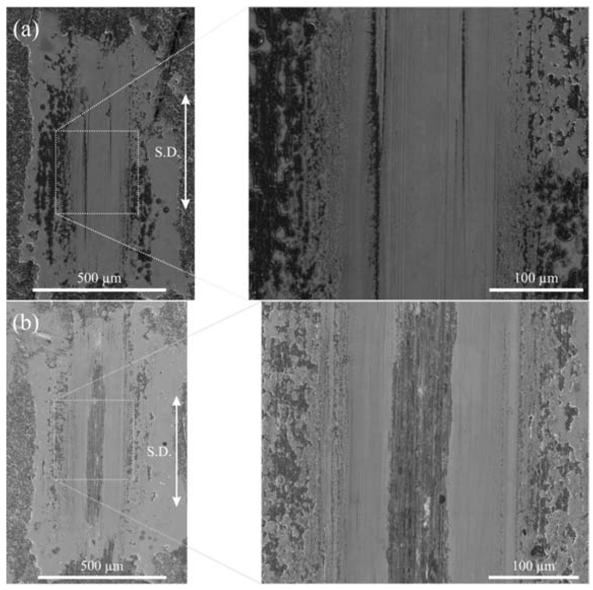
In Figure 5, the corresponding wear tracks for the CNT-coated sample are displayed.
In case of the 200 sliding cycles, no severe wear of the nickel substrate can be noticed. Apart from slight scratches that might have been generated by larger asperities of the ball the Ni surface is still polished. It is worth mentioning that even after the tribological experiment, individual grains can still be recognized, which is only possible for highly-polished surfaces. Inside of the mentioned scratches, CNTs can be found which is verified by Raman spectroscopy. These CNTs, as well as the CNTs from the wear track end, can lubricate the sample, thus preventing the occurrence of severe wear. In general, the absence of severe wear demonstrates that the temporal evolution of the COF for 200 cycles is mainly dominated by the contact of the CNT-coating with the counter body, acting as a protective layer for the Ni substrate. Furthermore, no oxide formation can be detected. This observation seems to be reasonable as there is almost no direct contact between the counter body and the Ni substrate. The lack of oxides might also contribute to the low COF observed for the 200 sliding cycles.
For 20,000 sliding cycles, two areas in the wear tracks can be distinguished. On the one hand, in the middle of the wear track, a small area (width between 60 and 70 µm) with severe wear and pronounced plowing as well as oxidation marks can be found. On the other hand, a wider wear track having some slight scratches and a similar appearance compared to the wear track observed after 200 sliding cycles is clearly visible. When comparing the wear track widths after 200 and 20,000, it is noticeable that the wear track width is more or less constant. The area, where severe wear occurs might be connected to the increasing COF after 3000 cycles, when the Al2O3 ball potentially gets in full contact to the Ni substrate. Thus, from this point on, the similar behavior of the COF compared to the Ni reference could be explained by this hypothesis. As for the reference, the dominating wear mechanism is most probably plowing. Additionally, similar to the reference, an oxide formation can be observed in the middle. Moreover, at the ends of the wear track, oxidic wear particles are deposited. The formation of these particles mainly contributes to the increasing COF during run-in, thus showing a similar frictional behavior as the reference. However, in contrast to the Ni reference, the width of the area with severe wear occurrence is decreased which might be due to the CNTs that avoid the direct contact of the flanks of the ball with the Ni substrate.
In Figure 6, the wear track on the CNT-reinforced sample after 20,000 cycles is depicted.
Although the dominating wear mechanism is, again, plowing, the wear track seems to be very inhomogeneous. In some areas, severe wear occurs, whereas other parts are nearly unaffected. Having a closer look at the areas with less wear, it can be observed that CNT clusters are present in these areas. As a consequence, the inhomogeneous wear track can be well correlated with the distribution of the CNT clusters within the composite. In addition to this, a large amount of oxidic wear particles can be found at the ends of the wear track, but less oxidic wear particles can be determined within the wear track. It might be reasonable to assume that these particles are shifted out of the contact zone, thus having a reduced influence of the resulting COF. Additionally, as there is a continuous supply of “fresh” CNTs during the tribological measurement, the sample is always lubricated. Noticing that the COF is not as low as in the beginning of the measurement of the CNT-coated sample, this mainly seems to be a function of the amount of CNTs involved in the process and present in the tribological contact zone. Consequently, a better distribution of CNT clusters, as well as a higher amount in the contact zone would probably lower the resulting COF to a larger extent and allows for improved wear protection of the composite material. This is currently subject of ongoing research work and will be published by the authors in a follow-up paper.

2.3. Structural and Chemical Analysis of the Wear Tracks

Raman spectroscopy is widely recognized as the most suitable technique to assess the structural state of sp2 carbon materials. In the specific case of CNTs, this technique provides very useful information for the proper description of their defect and purity state [40]. Within the typical resonances in CNTs, the most relevant are the D (defect-related), G (graphitic lattice-related), and G′ (second order resonance, purity-related) bands [41]. Additionally, the analysis of the FWHM of the G band (ΓG) depict the evolution of the crystallinity of the graphitic lattice [37]. Finally, it has been empirically shown that the distance between defects is related to the excitation wavelength (λ) of the spectrometer and the intensity ratio of the D and G band [42,43]. This distance can, thus, be calculated by [43]:
L a = ( 2.4 × 10 10 ) · λ laser 4 · ( I D I G ) 1
It is important to consider that, since Raman spectroscopy is a volume-sensitive technique, it is necessary to normalize the information (to the peak with the maximum intensity) and that only a comparison of intensity ratios provides reliable information.
For this study, we focused our analysis on the most relevant structural indicators obtained by Raman spectroscopy, namely: defect index (ID/IG), purity index (IG′/ID), G-band center position (XCG), crystallinity (ΓG), and mean inter-defect distance (La).
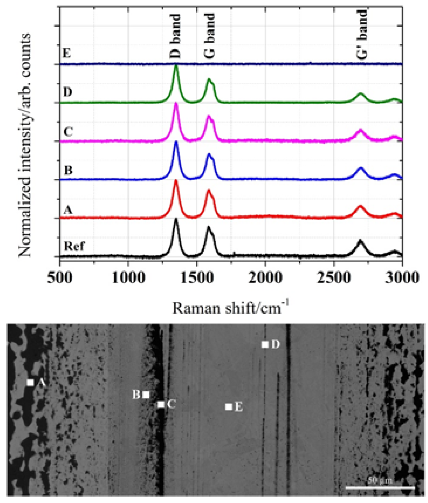
Figure 7 shows the spectra of different positions within and outside the wear track for the CNT-coated sample after 200 sliding cycles. Region A lies outside the contact zone, region B consists of distributed carbon phase within the track, region C contains distributed agglomerates inside the track, region D contains CNTs within a wear scratch and, finally, region E is at the center of the wear track. Generally, all spectra show a similar peak distribution except for that taken at spot E. In this case, there are no peaks whatsoever, representing a typical result of a pure metal. It is well known that metals with either fcc, hcp, or bcc crystal lattices present no first-order Raman spectra [44]. Interestingly, by considering the quantitative analysis of the Raman data presented in Table 1, several conclusions can be drawn. First, a clear degradation of the CNTs structural quality can be observed as we move towards the center of the wear track. This is supported by an increasing ID/IG ratio and certainly, by a reduction in the mean inter-defect distance. However, the crystallinity does not show a significant deviation within the measured values, thus withstanding a possible conclusion in this respect. Regarding the purity index, it follows a similar behavior as the crystallinity, being directly related to the deterioration of the graphitic structure into an amorphous-type sp2 carbon phase.
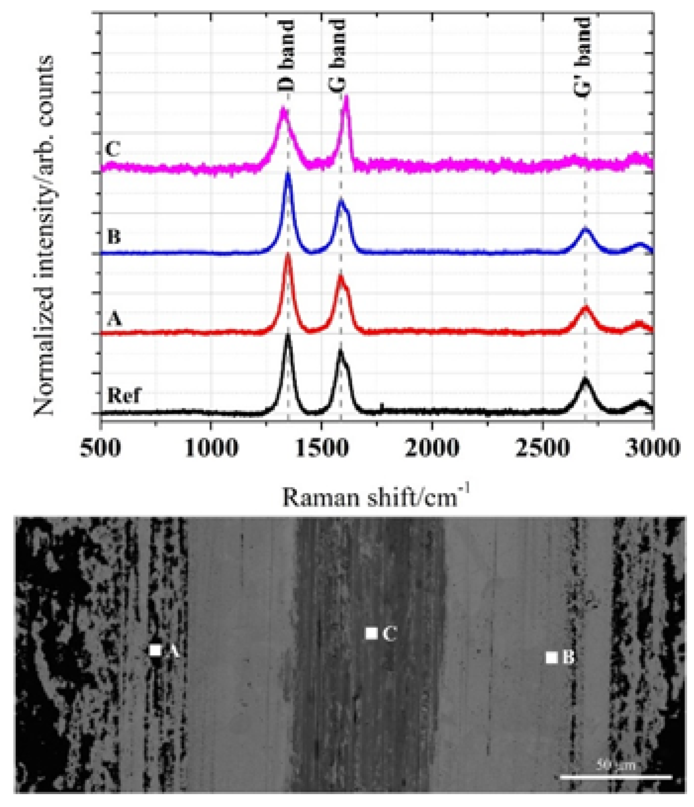
The Raman spectra of the CNT-coated sample tested for 20,000 sliding cycles are shown in Figure 8. Here, three different regions are clearly noticeable. Region A is on the edge of the track, where apparently lightly modified CNTs are. Region B lies within the contact zone, where the CNTs seem to be embedded in the matrix. Finally, region C (light grey zone) is where the highest contact pressure was applied.
The quantification of the Raman spectra (Table 2) provides similar results as those shown for 200 cycles regarding tendencies on the different intensity ratios analyzed. However, due to the longer measuring time, the effects become more evident. Specifically, there is a clear increment in the defect ratio (and subsequently, the inter-defect distance), related to the increased exposure time to the tribological contact. Furthermore, the quality indicators (purity index and crystallinity) show a strong degradation of the CNTs towards a different carbon configuration, namely amorphous nano-carbons. This is also strongly supported by the G-band shift towards a higher Raman shift [45].
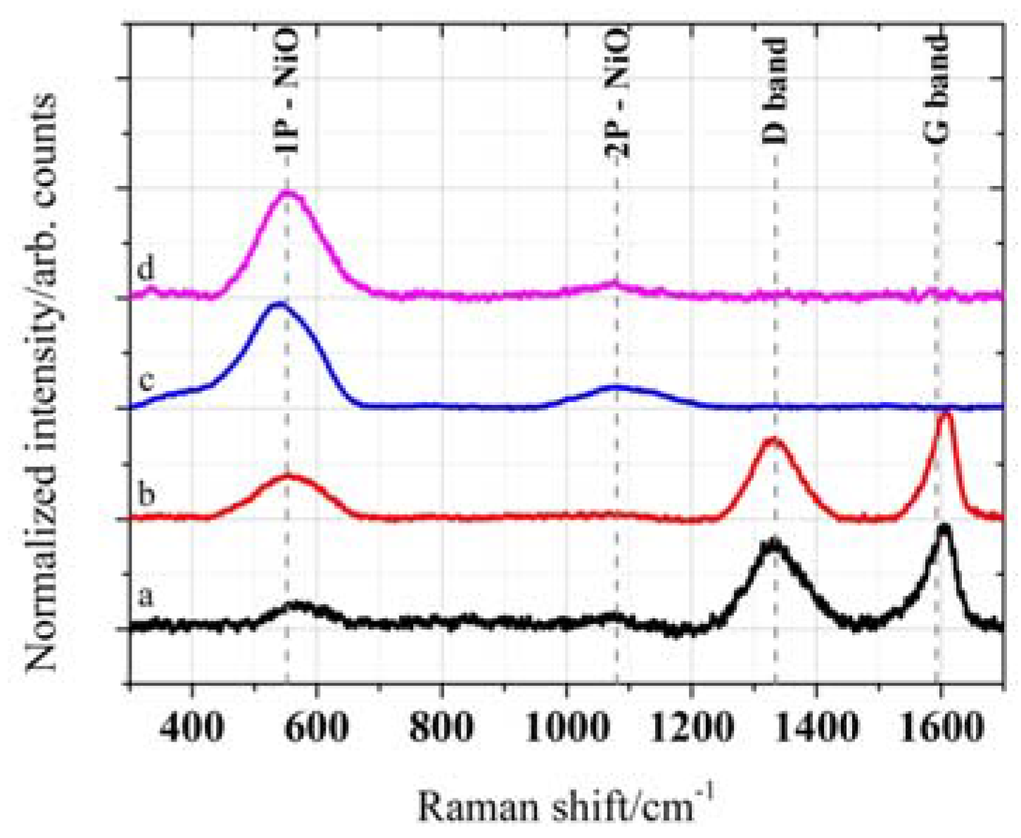
Regarding the surface chemistry after the tribological experiments, all studied cases showed the presence of Ni oxide (NiO) [46,47]. This is straightforwardly detected with Raman spectroscopy by observing the resonance at 550 and 1100 cm−1.
Specifically, the peak at 550 cm−1 corresponds to a one-phonon (1P) scattering and the peak at 1100 cm−1 corresponds to a two-phonon (2P) scattering process [46,47]. Figure 9 shows the spectra of the samples in the range of interest. The 1P scattering is detected in all the samples, whereas 2P is observable only in the reference sample, even after only 200 cycles. This would indicate that the oxidation activity was stronger in the absence of CNTs which is related to the capability of the CNTs to avoid the direct exposure of the metal to the environment. Particularly, in the case of the CNT-coated samples, the protection is evident. However, in the case of the CNT-reinforced Ni, the behavior is quite different. The protection is achieved only after a CNT-layer is formed after run-in, where the CNTs are provided by the agglomerates present within the matrix.
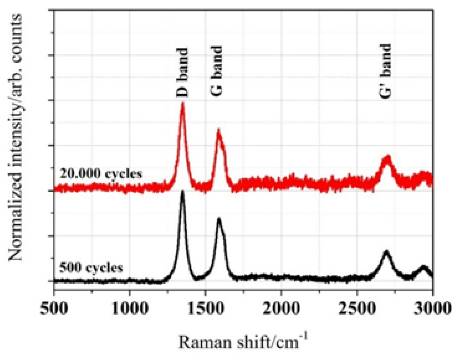
Finally, we analyzed the state of the CNTs that were transferred from the coating to the counter body during the experiment. The Raman spectra and its subsequent quantitative analysis are shown in Figure 10 and Table 3, respectively. As for the substrate, an increment in the defect ratio and the inter-defect distance can be observed which is proportional to the increasing exposure time of the CNTs in the tribological contact.

3. Experimental Section

3.1. Materials

Commercially available multi-walled CNTs (Baytubes C150P from Bayer (Leverkusen, Germany), purity >95%, individual particle diameter of 5–20 nm) and dendritic Ni powder (Alfa Aesar (Karlsruhe, Germany), maximum particle size of 44 µm, purity of 99.8%) were used as starting materials. They were blended by a colloidal mixing process using ethylene glycol as solvent. In order to ensure good dispersion, a homogenizer (WiseTis, Witeg) and an ultrasonic bath (Sonorex Super RK 514, Bandelin, 860 W, 35 kHz) were employed for five and 20 min, respectively. These processing parameters, as well as a concentration of 0.006 vol% of CNTs in the solvent were chosen according to previous studies [26]. In a previous study, the zeta-potential of this system was determined to be 21.7 ± 1.4 mV [26].
After the dispersion process, the solvent was evaporated in a furnace at 150 °C. The obtained powder mixtures were used to fabricate nickel matrix composites with 1 wt % MWCNTs. In order to do so, the powder was consolidated using an axial pressure of 990 MPa to generate cylindrical samples with a diameter of 8 mm. Afterwards, these samples were densified in a hot uniaxial press under vacuum (10−4 Pa) at 1023 K for 2.5 h.
The CNT-coated Ni samples were manufactured by drop-casting. The suspension consisted of a dispersion of the already-described CNTs in ethylene glycol with a concentration of 0.4 mg/mL. The deposition process was based on the pre-heating of the sample up to 150 °C and the sequential drop deposition up to an accumulated amount of 20 drops. The individual drop volume was 50 µL. After the first drying step (drop evaporation), the samples were dried in a ventilated furnace at 200 °C for 2 h, in order to fully remove the remaining solvent.

3.2. Chemical Characterization and Wear Track Analysis

After the fabrication of the nickel matrix composites, the samples were grinded and polished (ending with a 1 µm diamond polishing suspension) in order to guarantee a good surface quality with a root mean square roughness of 2.8 ± 0.5 nm.
Prior to and after the tribological experiments, Raman spectra were recorded using an inVia Raman microscope (Renishaw) with an excitation wavelength of 532 nm in order to study the quality of the CNTs and to investigate tribo-oxidational effects. The data was recorded using a grating with 2400 lines per mm, a 50x-objective (numeric aperture: 0.9) and a laser power of 0.2 mW. The optical elements of the Raman microscope used in this analysis produced a laser spot size of roughly 5 µm (full width at half maximum), a spectral resolution of about 1.2 cm−1 and a penetration depth of approximately 1 µm.
After the tribological measurements, the samples were imaged by light microscopy (BX 60, Olympus) or scanning electron microscopy (Helios Nanolab 600, FEI) in order to investigate the wear tracks which can get a hint to the underlying friction and wear mechanisms. For scanning electron microscopy, a voltage of 5 kV was applied using a working distance of 4 mm.

3.3. Tribological Experiments

Tribological experiments under dry sliding conditions were conducted using a ball-on-disk tribometer (CSM Instruments) in linear reciprocating sliding mode with a stroke length of 0.6 mm, a maximum sliding speed of 1 mm/s and a normal load of 100 mN. The number of cycles was set to be 200 and 20,000 cycles in order to study the run-in behavior and the long-term stability of the fabricated samples (CNT-composites and CNT-coated samples). The counter body was an Al2O3 ball with a diameter of 6 mm. This ball material was chosen to avoid any plastic deformation of the counter body. The ball is mounted on a cantilever with a stiffness of 0.7624 µN/µm in normal and 1.1447 µN/µm in tangential direction. During the experiment, the deflections of the cantilever in the horizontal and vertical direction are measured using optical fiber displacement sensors. Consequently, the normal and friction force can be calculated, thus, resulting in the continuous measurement of the COF with a frequency of 100 Hz. A mean value for each sliding cycle was then calculated from the absolute measured raw values of one forward and backward motion, excluding the data obtained at the reversal points. Finally, the mean value of each sliding cycle was plotted as a function of the total sliding cycles. Temperature and relative humidity were kept constant at 20 ± 2 °C and 4% ± 1%, respectively.

4. Conclusions

In this work, we were able to compare (by fixing the testing parameters) the frictional behavior of CNT-reinforced and CNT-coated samples. With regard to the tribological short-term experiments (200 sliding cycles), both samples induce a significant friction reduction (roughly by a factor of four) under dry friction, compared to the polished reference. It can be stated that the frictional behavior is mainly influenced by the CNTs present in the contact zone, as no difference in the COF between both samples can be observed. As a consequence, the known effect of a refined microstructure, thus leading to an increased hardness of the CNT reinforced samples seems to play a minor role in friction reduction compared to the solid lubrication effect induced by the CNTs.
Regarding the tribological long-term experiments (20.000 sliding cycles), it could be observed that the friction reduction of the CNT-coated samples just lasts for the first 3000 cycles after which the COF approaches the value of the reference. This can be explained by the gradual removal of CNTs from the contact zone. In contrast to that, the CNT-reinforced sample demonstrates a pronounced friction reduction over the entire 20.000 sliding cycles, which can be attributed mainly to the continuous supply of CNTs to the contact zone. In conjunction to the mentioned points, the generation of wear particles and the formation of an oxide layer (high shear strength layer) have to be taken into consideration. In this context, CNTs proved to act as an efficient barrier to avoid the oxidation of the contact region during the experiments. The avoidance of the oxidation turns out very useful, since the generation of a superficial oxide would unavoidably increase the COF due to an increased shear strength.
Regarding the structural resistance of the CNTs during the tribological experiments, we were able to show that even for extended test duration, the CNTs can withstand the accumulated stress, retaining to some extent their structural state. The occurrence of amorphous nano-carbons within the wear track of the CNT-reinforced sample and their effect on the tribological properties of the composite is subject of ongoing research work and will be published by the authors in a follow-up paper.

Acknowledgments

The present work is supported by funding from the Deutsche Forschungsgemeinschaft (DFG, project: MU 959/38-1 and project: SU 911/1-1). The authors wish to acknowledge the EFRE Funds of the European Commission for support of activities within the AME-Lab project. This work was supported by the CREATe-Network Project, Horizon 2020 of the European Commission (RISE Project No. 644013).

Author Contributions

Leander Reinert and Andreas Rosenkranz manufactured the samples as well as designed, performed and analyzed the tribological experiments. Leander Reinert and Sebastian Suárez measured and analyzed the Raman spectroscopy data. All authors discussed and wrote the manuscript.

Conflicts of Interest

The authors declare no conflict of interest.

References

  1. Lu, Y.; Liaw, P.K. The mechanical properties of nanostructured materials. JOM 2001, 53, 31–35. [Google Scholar] [CrossRef]
  2. Kim, P.; Shi, L.; Majumdar, A.; McEuen, P. Thermal transport measurements of individual multiwalled nanotubes. Phys. Rev. Lett. 2001, 87, 215502. [Google Scholar] [CrossRef] [PubMed]
  3. Chen, W.X.; Tu, J.P.; Wang, L.Y.; Gan, H.Y.; Xu, Z.D.; Zhang, X.B. Tribological application of carbon nanotubes in a metal-based composite coating and composites. Carbon 2003, 41, 215–222. [Google Scholar] [CrossRef]
  4. Kim, K.T.; Cha, S.I.; Hong, S.H. Hardness and wear resistance of carbon nanotube reinforced Cu matrix nanocomposites. Mater. Sci. Eng. A 2007, 449–451, 46–50. [Google Scholar] [CrossRef]
  5. Scharf, T.W.; Neira, A.; Hwang, J.Y.; Tiley, J.; Banerjee, R. Self-lubricating carbon nanotube reinforced nickel matrix composites. J. Appl. Phys. 2009, 106. [Google Scholar] [CrossRef]
  6. Tan, J.; Yu, T.; Xu, B.; Yao, Q. Microstructure and wear resistance of nickel–carbon nanotube composite coating from brush plating technique. Tribol. Lett. 2006, 21, 107–111. [Google Scholar] [CrossRef]
  7. Guiderdoni, C.; Estournès, C.; Peigney, A.; Weibel, A.; Turq, V.; Laurent, C. The preparation of double-walled carbon nanotube/Cu composites by spark plasma sintering, and their hardness and friction properties. Carbon 2011, 49, 4535–4543. [Google Scholar] [CrossRef] [Green Version]
  8. Dorri Moghadam, A.; Omrani, E.; Menezes, P.L.; Rohatgi, P.K. Mechanical and tribological properties of self-lubricating metal matrix nanocomposites reinforced by carbon nanotubes (CNTs) and graphene—A review. Compos. Part B Eng. 2015, 77, 402–420. [Google Scholar] [CrossRef]
  9. Omrani, E.; Moghadam, A.; Menezes, P.L.; Rohatgi, P.K. New emerging self-lubricating metal matrix composites for tribological applications. Ecotribology 2016, 63–103. [Google Scholar] [CrossRef]
  10. Hirata, A.; Yoshioka, N. Sliding friction properties of carbon nanotube coatings deposited by microwave plasma chemical vapor deposition. Tribol. Int. 2004, 37, 893–898. [Google Scholar] [CrossRef]
  11. Hu, J.J.; Jo, S.H.; Ren, Z.F.; Voevodin, A.; Zabinski, J.S. Tribological behavior and graphitization of carbon nanotubes grown on 440C stainless steel. Tribol. Lett. 2005, 19, 119–125. [Google Scholar] [CrossRef]
  12. Miyoshi, K.; Street, K.W., Jr.; Vander Wal, R.L.; Andrews, R.; Sayir, A. Solid lubrication by multiwalled carbon nanotubes in air and in vacuum. Tribol. Lett. 2005, 19, 191–201. [Google Scholar] [CrossRef]
  13. Dickrell, P.L.; Pal, S.K.; Bourne, G.R.; Muratore, C.; Voevodin, A.; Ajayan, P.M.; Schadler, L.S.; Sawyer, W.G. Tunable friction behavior of oriented carbon nanotube films. Tribol. Lett. 2006, 24, 85–90. [Google Scholar] [CrossRef]
  14. Zhang, X.; Luster, B.; Church, A.; Muratore, C.; Voevodin, A.; Kohli, P.; Aouadi, S.; Talapatra, S. Carbon nanotube-MoS2 composites as solid lubricants. ACS Appl. Mater. Interfaces 2009, 1, 735–739. [Google Scholar] [CrossRef] [PubMed]
  15. Arai, S.; Fujimori, A.; Murai, M.; Endo, M. Excellent solid lubrication of electrodeposited nickel-multiwalled carbon nanotube composite films. Mater. Lett. 2008, 62, 3545–3548. [Google Scholar] [CrossRef]
  16. Chen, C.S.; Chen, X.H.; Xu, L.S.; Yang, Z.; Li, W.H. Modification of multi-walled carbon nanotubes with fatty acid and their tribological properties as lubricant additive. Carbon 2005, 43, 1660–1666. [Google Scholar] [CrossRef]
  17. Peng, Y.; Hu, Y.; Wang, H. Tribological behaviors of surfactant-functionalized carbon nanotubes as lubricant additive in water. Tribol. Lett. 2006, 25, 247–253. [Google Scholar] [CrossRef]
  18. Lu, H.F.; Fei, B.; Xin, J.H.; Wang, R.H.; Li, L.; Guan, W.C. Synthesis and lubricating performance of a carbon nanotube seeded miniemulsion. Carbon 2007, 45, 936–942. [Google Scholar] [CrossRef]
  19. Kristiansen, K.; Zeng, H.; Wang, P.; Israelachvili, J.N. Microtribology of Aqueous Carbon Nanotube Dispersions. Adv. Funct. Mater. 2011, 21, 4555–4564. [Google Scholar] [CrossRef]
  20. Coleman, J.N. Liquid-Phase Exfoliation of Nanotubes and Graphene. Adv. Funct. Mater. 2009, 19, 3680–3695. [Google Scholar] [CrossRef]
  21. Avilés, F.; Cauich-Rodríguez, J.V.; Moo-Tah, L.; May-Pat, A.; Vargas-Coronado, R. Evaluation of mild acid oxidation treatments for MWCNT functionalization. Carbon 2009, 47, 2970–2975. [Google Scholar] [CrossRef]
  22. Karousis, N.; Tagmatarchis, N.; Tasis, D. Current progress on the chemical modification of carbon nanotubes. Chem. Rev. 2010, 110, 5366–5397. [Google Scholar] [CrossRef] [PubMed]
  23. Dyke, C.A.; Tour, J.M. Solvent-free functionalization of carbon nanotubes. J. Am. Chem. Soc. 2003, 125, 1156–1157. [Google Scholar] [CrossRef] [PubMed]
  24. Vaisman, L.; Wagner, H.D.; Marom, G. The role of surfactants in dispersion of carbon nanotubes. Adv. Colloid Interface Sci. 2006, 128–130, 37–46. [Google Scholar] [CrossRef] [PubMed]
  25. Zhao, Y.-L.; Stoddart, J.F. Noncovalent Functionalization of Single-Walled Carbon Nanotubes. Acc. Chem. Res. 2009, 42, 1161–1171. [Google Scholar] [CrossRef] [PubMed]
  26. Reinert, L.; Zeiger, M.; Suarez, S.; Presser, V.; Mücklich, F. Dispersion analysis of carbon nanotubes, carbon onions, and nanodiamonds for their application as reinforcement phase in nickel metal matrix composites. RSC Adv. 2015, 5, 95149–95159. [Google Scholar] [CrossRef]
  27. Cheng, Q.; Debnath, S.; Gregan, E.; Byrne, H.J. Ultrasound-Assisted SWNTs Dispersion: Effects of Sonication Parameters and Solvent Properties. J. Phys. Chem. C 2010, 114, 8821–8827. [Google Scholar] [CrossRef]
  28. Variava, M.F.; Church, T.L.; Harris, A.T.; Minett, A.I. Polyol-assisted functionalization of carbon nanotubes—A perspective. J. Mater. Chem. A 2013, 1, 8509. [Google Scholar] [CrossRef]
  29. Suárez, S.; Rosenkranz, A.; Gachot, C.; Mücklich, F. Enhanced tribological properties of MWCNT/Ni bulk composites – Influence of processing on friction and wear behaviour. Carbon 2014, 66, 164–171. [Google Scholar] [CrossRef]
  30. Chen, X.H.; Chen, C.S.; Xiao, H.N.; Liu, H.B.; Zhou, L.P.; Li, S.L.; Zhang, G. Dry friction and wear characteristics of nickel/carbon nanotube electroless composite deposits. Tribol. Int. 2006, 39, 22–28. [Google Scholar] [CrossRef]
  31. Dickrell, P.L.; Sinnott, S.B.; Hahn, D.W.; Raravikar, N.R.; Schadler, L.S.; Ajayan, P.M.; Sawyer, W.G. Frictional anisotropy of oriented carbon nanotube surfaces. Tribol. Lett. 2005, 18, 59–62. [Google Scholar] [CrossRef]
  32. Colonna, F.; Fasolino, A.; Meijer, E.J. Graphitization of single-wall nanotube bundles at extreme conditions: Collapse or coalescence route. Phys. Rev. B 2013, 88, 165416. [Google Scholar] [CrossRef]
  33. Bakshi, S.R.; Agarwal, A. An analysis of the factors affecting strengthening in carbon nanotube reinforced aluminum composites. Carbon 2011, 49, 533–544. [Google Scholar] [CrossRef]
  34. Hwang, J.Y.; Neira, A.; Scharf, T.W.; Tiley, J.; Banerjee, R. Laser-deposited carbon nanotube reinforced nickel matrix composites. Scr. Mater. 2008, 59, 487–490. [Google Scholar] [CrossRef]
  35. Suarez, S.; Soldera, F.; González Oliver, C.; Acevedo, D.; Mücklich, F. Thermomechanical Behavior of Bulk Ni/MWNT Composites Produced via Powder Metallurgy. Adv. Eng. Mater. 2012, 14, 499–502. [Google Scholar] [CrossRef]
  36. Suarez, S.; Lasserre, F.; Mücklich, F. Mechanical properties of MWNT/Ni bulk composites: Influence of the microstructural refinement on the hardness. Mater. Sci. Eng. A 2013, 587, 381–386. [Google Scholar] [CrossRef]
  37. Suarez, S.; Lasserre, F.; Prat, O.; Mücklich, F. Processing and interfacial reaction evaluation in MWNT/Ni bulk composites. Phys. Status Solidi 2014, 211, 1555–1561. [Google Scholar] [CrossRef]
  38. Blau, P.J. On the nature of running-in. Tribol. Int. 2005, 38, 1007–1012. [Google Scholar] [CrossRef]
  39. Shafiei, M.; Alpas, A.T. Friction and Wear Mechanisms of Nanocrystalline Nickel in Ambient and Inert Atmospheres. Metall. Mater. Trans. A 2007, 38, 1621–1631. [Google Scholar] [CrossRef]
  40. Lehman, J.H.; Terrones, M.; Mansfield, E.; Hurst, K.E.; Meunier, V. Evaluating the characteristics of multiwall carbon nanotubes. Carbon 2011, 49, 2581–2602. [Google Scholar] [CrossRef]
  41. Jorio, A.; Dresselhaus, M.; Dresselhaus, G. Carbon Nanotubes: Advanced Topics in the Synthesis, Structure, Properties and Applications; Springer-Verlag: Heidelberg, Germany, 2008; p. 720. [Google Scholar]
  42. Tuinstra, F.; Koenig, J.L. Raman Spectrum of Graphite. J. Chem. Phys. 1970, 53, 1126–1130. [Google Scholar] [CrossRef]
  43. Pimenta, M.A.; Dresselhaus, G.; Dresselhaus, M.S.; Cançado, L.G.; Jorio, A.; Saito, R. Studying disorder in graphite-based systems by Raman spectroscopy. Phys. Chem. Chem. Phys. 2007, 9, 1276–1291. [Google Scholar] [CrossRef] [PubMed]
  44. Creighton, J.A.; Withnall, R. The Raman spectrum of gallium metal. Chem. Phys. Lett. 2000, 326, 311–313. [Google Scholar] [CrossRef]
  45. DiLeo, R.A.; Landi, B.J.; Raffaelle, R.P. Purity assessment of multiwalled carbon nanotubes by Raman spectroscopy. J. Appl. Phys. 2007, 101, 064307. [Google Scholar] [CrossRef]
  46. Mironova-Ulmane, N.; Kuzmin, A.; Steins, I.; Grabis, J.; Sildos, I.; Pärs, M. Raman scattering in nanosized nickel oxide NiO. J. Phys. Conf. Ser. 2007, 93, 012039. [Google Scholar] [CrossRef]
  47. Mironova-Ulmane, N.; Kuzmin, A.; Grabis, J.; Sildos, J.; Voronin, V.I.; Berger, I.F.; Kazantsev, V.A. Structural and Magnetic Properties of Nickel Oxide Nanopowders. Solid State Phenom. 2011, 168–169, 331–334. [Google Scholar] [CrossRef]
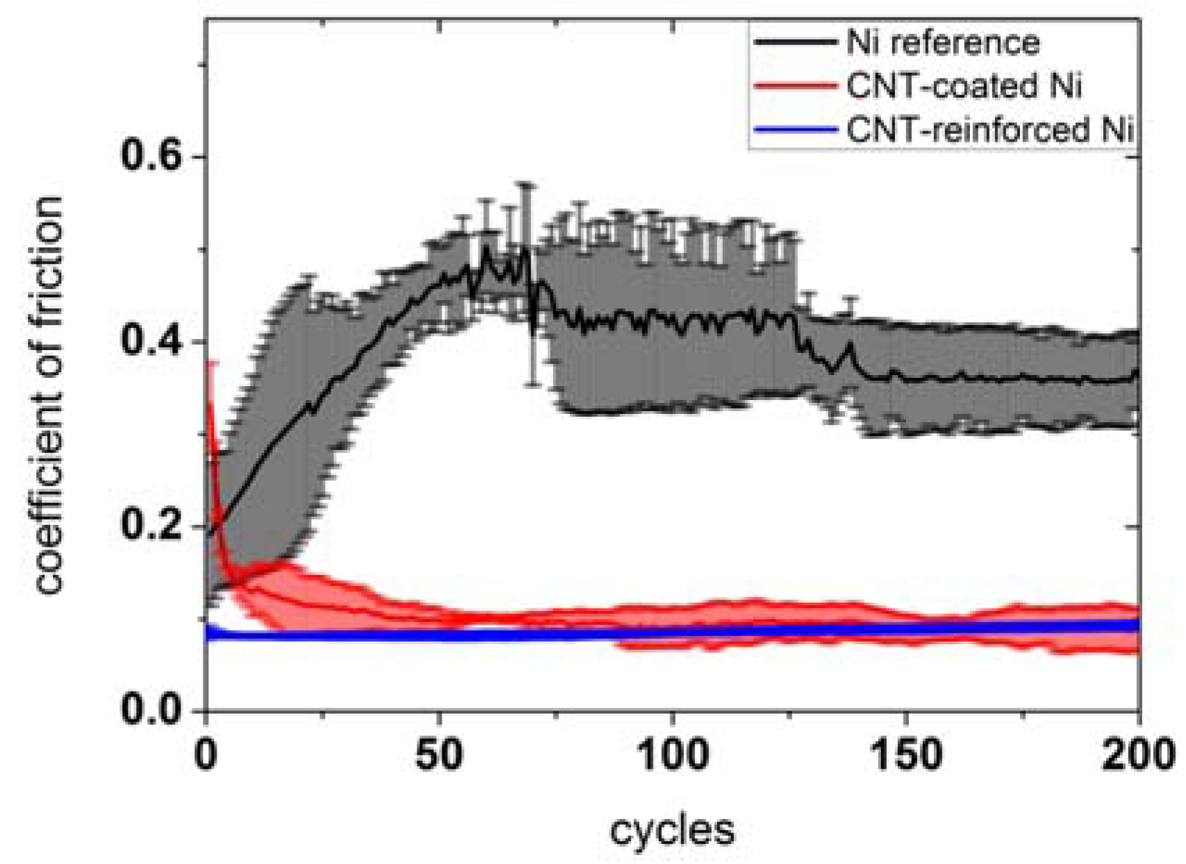
Figure 1. Temporal evolution of the COF plotted as a function of the number of sliding cycles for a sintered Ni reference, a CNT-coated, and a CNT-reinforced sample.
Lubricants 04 00011 g001
Figure 2. Light microscope picture of the Al2O3 counter body having rubbed against the CNT-coated sample for 200 sliding cycles.
Lubricants 04 00011 g002
Figure 3. Temporal evolution of COF plotted against the number of sliding cycles for a Ni reference, a CNT-coated sample, and a CNT-reinforced sample.
Lubricants 04 00011 g003
Figure 4. Wear tracks after 200 (a) and 20,000 (b) sliding cycles on the Ni reference. Detailed images of the middle of the wear tracks (highest sliding velocity) are given using a higher magnification.
Lubricants 04 00011 g004
Figure 5. Wear tracks of the CNT-coated sample after 200 (a) and 20,000 sliding cycles (b). Detailed images of the middle of the wear tracks (highest sliding velocity) are given using a higher magnification.
Lubricants 04 00011 g005
Figure 6. Wear track of the CNT-reinforced sample after 20,000 sliding cycles (b) imaged at different positions. The upper part of the wear track (a) as well as the middle (c) are shown in a higher magnification.
Lubricants 04 00011 g006
Figure 7. Raman spectra of different spots of the wear track taken from the CNT-coated sample after 200 sliding cycles.
Lubricants 04 00011 g007
Figure 8. Raman spectra of different spots of the wear track taken from the CNT-coated sample after 20,000 sliding cycles.
Lubricants 04 00011 g008
Figure 9. Raman spectra of the studied samples in the range from 300 to 1700 cm−1. (a) CNT-reinforced Ni 20,000 cycles; (b) CNT-coated Ni 20,000 cycles; (c) Ni reference 200 cycles; and (d) Ni reference 20,000 cycles. The resonance bands for NiO (1P and 2P) and sp2 carbon (D and G) are shown for comparison.
Lubricants 04 00011 g009
Figure 10. Raman spectra of the transferred CNTs from the coating to the counter body (alumina ball).
Lubricants 04 00011 g010
Table 1. Descriptive parameters obtained by Raman spectroscopy of the CNT-coated sample after 200 sliding cycles.
PositionID/IGIG′/IDXCG (cm−1)ΓG (cm−1)La (nm)
Reference1.2470.4351593.073.915.4
A1.3600.3191593.962.314.1
B1.4610.3141594.479.113.2
C1.5110.3131593.175.912.7
D1.5910.2511594.875.612.1
E---------------
Table 2. Descriptive parameters obtained by Raman spectroscopy of the CNT-coated sample after 20,000 sliding cycles.
PositionID/IGIG’/IDXCG (cm−1)ΓG (cm−1)La (nm)
Reference1.2470.4351593.073.915.4
A1.3730.3031592.380.214.0
B1.4930.2941594.293.812.9
C------1607.1------
Table 3. Descriptive parameters obtained by Raman spectroscopy of the CNT-coated sample after 20,000 sliding cycles.
PositionID/IGIG′/IDXCG (cm−1)ΓG (cm−1)La (nm)
Reference1.2470.4351593.073.915.4
5001.4360.3361594.173.813.4
20,0001.5210.3871594.984.512.6