Abstract
This study was a continuous investigation of the roles played by the tribofilm on dry automotive clutch system performance. Tribological experiments were performed by the addition of wear debris at the beginning of tribometer tests and by reducing the surface roughness of a cast iron counter-face. The initial surface conditions of cast discs were 0.2 and 1.2 µm. The pin-on-disc tests were carried out at three different PV levels: 3.08, 7.88, and 10.09 MPa·ms−1, and the current results were correlated to those previously obtained in the standard tribometer procedure. When the wear debris was added into the tribosystem, the friction coefficient level dropped drastically while the assembly wear rate rose. In contrast, the modified cast discs provided a reduced wear rate of assembly and a higher and more stable friction coefficient level. These improvements were obtained in a severe condition where higher temperature levels were reached. For the tests with added debris, SEM observations revealed a more intense tribofilm development over the worn surfaces of the clutch friction material. The smoothest cast disc did not damage the developed tribofilms and maintained them more stably due to a reduction in contact area stresses at the highest tribometer test.
1. Introduction
During the clutch system engagement of an automotive car, sliding contact occurs between a polymeric compound and a metallic counter-face. The coefficient of friction (COF) level among this tribological couple must be high and stable in order to provide an efficient and regular torque transmission from the internal combustion engine to the gear box.
According to Bahadur [1], when polymeric materials slide against metallic counter-faces, material transfer occurs invariably from polymer to metal, and the counter-face roughness plays an important role both in the transfer process and in the tribofilm development. In order to optimize the tribological performance of dry friction materials intended for automotive applications, innovative algorithms have been developed [2,3,4,5]. These algorithms are able to predict the wear properties of polymer-matrix composites.
In dry automotive clutches, neither the material transference nor the role that the tribofilm plays on the system performance has been investigated. In addition, in order to develop more efficient clutch systems, it has become necessary to achieve better control over their tribological characteristics.
Due to the bibliographical lack of information, Fernandes and colleagues investigated the tribofilm roles on the efficiency of dry clutch systems through tribological tests in a pin-on-disc tribometer [6,7,8,9,10]. This research pointed out a range of PV levels, where a continuous tribofilm developed between the cast iron disc and clutch friction material [7]. This developed tribofilm seems to be responsible for maintaining the friction and wear coefficients approximately constant. Once the PV range overcome, the tribofilm failed, and COF levels sharply decreased while wear rate rose. Further investigations carried out by Fernandes et al. [9], in which tribometer tests were made by removing the wear debris from the cast iron surface, led to the following conclusions: (1) The clutch system performance was controlled by the tribofilm development; (2) the COF and wear rate performance, tribofilm’s thickness, morphologies and, chemical composition were strongly affected by the interfacial temperature; (3) the removal of wear debris resulted in the increase in COF, while wear rate decreased due to a less developed tribofilm, which might both reduce the abrasivity into interfacial contact and increase the thermal conductivity of the tribosystem.
Previous studies pointed out that a more detailed investigation would be necessary to improve the relationship between the tribological couple characteristics and tribofilm development and to provide accurate information of the tribofilm importance. In this work, in order to study such influence on the COF and the wear rate performance, tribometer tests were performed by adding wear debris into the sliding contact. The roles played by the cast iron disc counter-face were also investigated by preconditioning their initial surface roughness in two different conditions.
2. Materials and Methods
The materials and methods employed in this work were equal to those used in the previously studies [6,7,8,9,10,11,12,13,14].
The clutch friction material was a semi-metallic, resin-bonded composite intended for heavy-duty commercial vehicles. It contains the most important constituents normally used in conventional automobile clutch systems, such as phenolic resins; organic, inorganic and metallic fibers; abrasives; lubricants; and other ingredients. Round specimens measuring 13 mm in diameter and 4 mm in height were cut from an unworn clutch friction material.
A commercial grey cast iron disc containing a perlitic matrix with less than 5% of free ferrite and graphite flakes homogeneously distributed and oriented in the matrix was used as the counter body. The diameter and thickness of the cast disc was 74 mm and 5 mm, respectively, and the average contact radius of the wear track was 26 mm. The disc was rotated on a horizontal plane, and the pin remained stationary. The test temperature was monitored using a thermocouple installed on the back of the cast disc. Its position was in the middle of the wear track and 2 mm from the sliding surface. The frequency of acquisition data of thermocouple was 1 Hz.
The tribological tests were performed in a lab using a pin-on-disc tribometer, and the PV levels employed were 3.08, 7.88, and 10.09 MPa·ms−1, which were classified as sub-mild, mild, and severe by Fernandes et al. [9].
In the sub-mild condition, the speed of test was 2.05 ms−1, and the specific pressure was 1.18 MPa. In mild and severe regime, the speed was 3.27 ms−1. However, the specific pressures were different, whereas in mild condition it was 1.89 MPa; in severe condition, 2.42 MPa.
In this work, two different test procedures were adopted. In the first one wear debris was spread over the cast iron surface before the tribological tests began (Figure 1a). In each test, the average amount added was 0.5 g, and it was controlled using the precision five-decimal balance Shimadzu model AUW 220D with a resolution of 0.01 mg (Figure 1b gives an example).

Figure 1.
Pin-on-disc tribological test through the addition of wear debris: (a) Wear debris spread over the cast iron disc surface at the beginning of the test; (b) average amount of wear debris added in each test; (c) morphologies of wear debris collected from the dynamometer test and observed in SEM.
The wear debris was collected from dynamometer tests since the amount generated during the tribometer tests was quite few. Moreover, the tribometer tribosystem has presented very good agreement with the dynamometer tribosystem, as has been demonstrated by Fernandes and colleagues [10,11,12,13,14].
In the second procedure, the cast iron disc surfaces were preconditioned at two different roughnesses: 1.2 µm and 0.2 µm (based on results presented by Dowson et al. [15]). The standard discs used in the tribometer were 3-µm-roughness. Figure 2 shows the frictional surfaces of preconditioned discs.
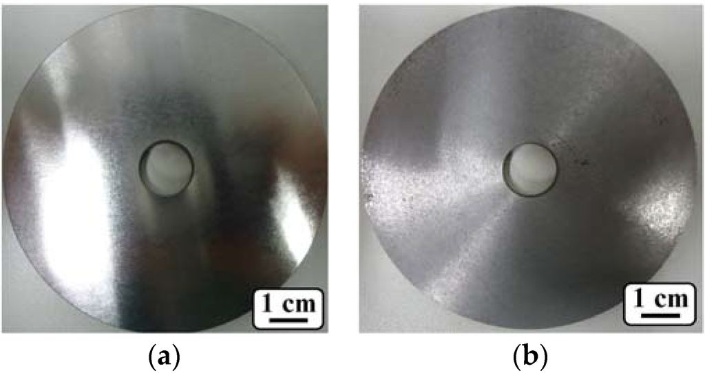
Figure 2.
Preconditioned cast iron disc: Ra of (a) 0.2 and (b) 1.2 µm.
3. Results
3.1. Temperature
The average test temperature level was calculated after it reached the steady-state regime, and Table 1 summarizes the obtained values for each tribometer test condition.

Table 1.
Average test temperature (°C) for each tribometer test condition.
3.2. Friction Coefficient
Table 2 summarizes the average COF for each performed test, and Figure 3 presents the COF evolution for the three tribometer test conditions.

Table 2.
Average coefficient of friction (COF) for each tribometer test condition.
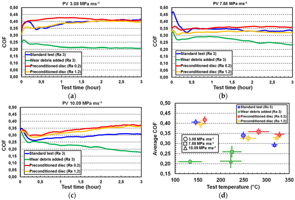
Figure 3.
COF evolution as function of testing time for PVs: (a) 3.08; (b) 7.88; and (c) 10.09 MPa·ms−1; (d) average COF plotted against average test temperature.
For the three PV tribometer conditions, the COF dropped significantly with the addition of wear debris, and their levels were lower than the standard results.
As presented in Figure 3a, the evolution of the 1.2-µm preconditioned disc COF was quite similar to the standard procedure at 3.08 MPa·ms−1. In the steady-state regime, both COFs were identical (close to 0.4), although the COF remained more stable and higher in the running-in period when used disc with Ra of 0.2 µm.
When PV changed to 7.88 MPa·ms−1 (Figure 3b), the COF fluctuation in the running-in period was lower when both preconditioned discs were used. However, the COF remained at the same level (0.35) that was obtained when the standard test was performed.
In the severe tribometer condition (PV of 10.09 MPa·ms−1—Figure 3c), the COF increased with test evolution, and they were also higher compared with the standard test.
Figure 3d presents the COF average plotted against test temperature. This figure reinforces the higher COF level for the tests performed in the severe wear regime using the preconditioned discs. In this condition, the test temperatures were above 300 °C.
3.3. Wear Rate
Table 3 summarizes the average assembly wear rate for each test condition, and Figure 4a,b present respectively the assembly and counter-face wear rates plotted versus test temperature. As can be seen in Figure 4a, the assembly wear rate increased significantly when the wear debris was added to the beginning of the tests. Using the preconditioned discs, the assembly wear rates were statistically equivalent to the standard condition at sub-mild and mild regimes.

Table 3.
Average assembly wear rate (mm3·MJ−1) for each tribometer test condition.
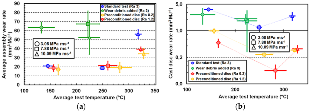
Figure 4.
Average wear rate plotted against average test temperature: (a) assembly; (b) counter-face.
At a PV of 10.09 MPa·ms−1, although the test temperature was considerably higher, the wear rate decreased 30% and 40% using the discs with Ra of 1.2 and 0.2 µm, respectively. Furthermore, it was observed that the counter-face wear rate decreased as surface disc roughness decreased. In addition, Figure 4b also reveals that the counter-face wear rates decreased when PV changed from 3.88 to 7.88 MPa·ms−1. It was due to the tribofilm development over the cast disc surface. The generated wear debris was more compressed in the second condition due to the higher specific pressure. For tests performed at 10.09 MPa·ms−1, the wear rate started to rise. In this specific condition, the action of glass fibers and copper fibers were more intense due to the higher specific pressure, and part of the tribofilm structure was destroyed.
3.4. Worn Surface Characterization
SEM observations (Figure 5) were performed after tribological tests only in the severe condition once improvements were observed for a PV of 10.09 MPa·ms−1.
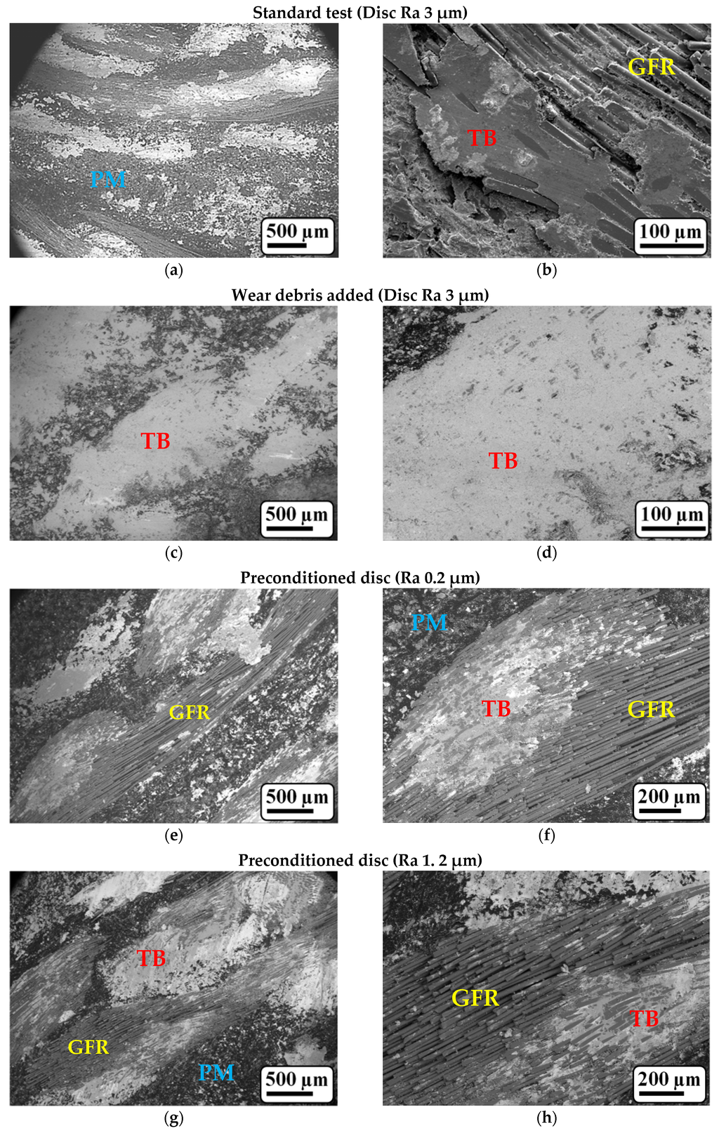
Figure 5.
Sliding surface of clutch friction material observed by SEM after tribometer tests performed at PV of 10.09 MPa·ms−1: (a,c,e,g) overview and (b,d,f,h) detail of tribofilm developed over GFR.
Fernandes et al. [9] pointed out that the polymeric matrix of clutch friction material tested in the standard procedure had thermally degraded. As shown in Figure 5b, the tribofilm developed over the glass fiber structure. Due to the test severity, it was damaged and, consequently, exposed the glass fiber to the contact surface again.
A well-developed tribofilm was observed on clutch friction material surface when the wear debris was added (Figure 5c), and, once more, the tendency of tribofilm development was over the glass fiber structure. At higher magnification (Figure 5d), it can be observed that all glass fibers were entirely covered by the developed tribofilm.
Although the sliding surface of clutch friction material tested with preconditioned discs presented characteristics quite similar to the standard procedure in the overview characterization (Figure 5a,e,g), their polymeric matrix was not thermally degraded, even at test temperatures higher than 300 °C. Moreover, the glass fibers were found not to be covered by the tribofilm, and the roving structure presented characteristics of a less developed tribofilm.
Figure 6 presents the topographic aspects of cast iron disc, and their sliding surface observed in SEM. The general aspect of the disc surface used at standard procedure was smooth. However, peaks generated by surface finishing tools were visible, and the SEM observation (Figure 6b) revealed that the tribofilm had developed only over part of the sliding surface.
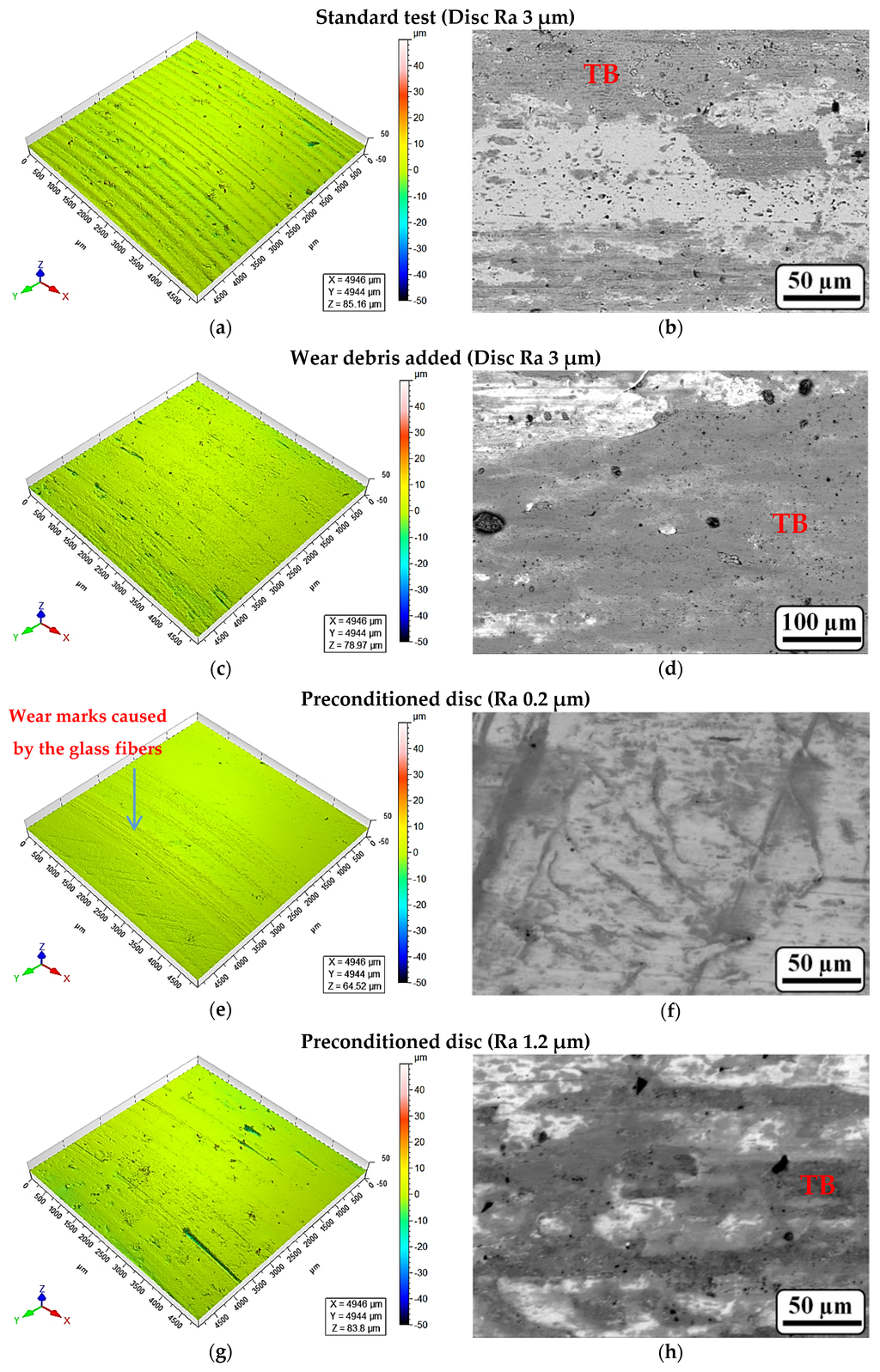
Figure 6.
Sliding surface of gray cast disc characterized by optical topographic analyzer (a,c,e,g) and by SEM (b,d,f,h) after tribometer tests performed at PV of 10.09 MPa·ms−1.
At the surface of the disc used in the tribometer test with the addition of wear debris, the topographic peaks were not found, and the sliding surface presented a very smooth topographical feature. The SEM analysis revealed that the wear track was entirely covered by the tribofilm.
After the tribological tests, the surfaces of preconditioned discs continued smoothly, and the tribofilm developed partially over the wear tracks. The development of tribofilm was more intense on the disc preconditioned at 1.2 µm.
4. Discussion
The presented results have shown that, when the wear debris was added, it helped to drop the COF level and to raise both the assembly and counter-face wear rates. The first tribological performance was significantly affected by the well-developed tribofilm, which probably acted as a solid lubricant, and the second was quite affected by the hard abrasive particles presented on wear debris, such as fragments of glass fibers, as can be seen in Figure 1c.
The higher average COF value achieved in the severe tribometer test condition might be associated with the glass fibers exposures (Figure 5f,h). As demonstrated by Kchaou et al. [16] and Sellami et al. [17], when the glass fibers were continuously exposed over the contact surface of brake friction material, higher levels of COF were obtained. Furthermore, according to Kishore et al. [18], the tribosystem responses depend on the fiber type, concentration, formulation, and distribution into the base. Another relation could be the manner that fibers emerge on the frictional surface as well.
Since the peaks generated on the topography of preconditioned discs by the surface finishing tool were reduced (see Figure 6e,g), the real contact area increased, reducing the specific contact pressure. Therefore, the wear debris generation was also reduced, helping to mitigate the tribofilm development. Although the tribofilms appeared partially over the glass fiber structures, their features revealed a non-breakage after being developed. This phenomenon contradicted the one observed in the standard procedure, where the tribofilm developed but, due to the test severity, was destroyed, exposing the glass fibers again and contributing to an increase in the assembly wear rate due to the hard abrasive particles generated [9].
Figure 6 reveals a less developed tribofilm over the cast disc surface when the tribometer tests were performed using the preconditioned discs. Moreover, the topographical analysis showed some abrasive scratches over the surface of preconditioned cast discs (see Figure 6e,g), probably generated by the exposition of glass fiber filaments at the sliding surface of the clutch friction material.
5. Conclusions
The most important conclusions from this study are:
- The addition of wear debris to interfacial contact drastically reduced the COF level and increased the assembly wear rates. Notably, it revealed that the tribological performance of the clutch is affected by the tribofilm development.
- Tribological tests using preconditioned cast iron discs provided a more stable COF in the running-in period, which may have provided a better clutch performance in the first cycles of engagement, when the frictional surfaces of clutch friction materials are not bedding.
- Clutch tribological performances (assembly wear rate and COF level) were quite improved in the severe wear condition only by the reduction in cast iron disc roughness.
Acknowledgments
The authors would like thank to the ZF Group for the continuous support to the research at the R&D Friction Materials Department in Brazil, as well as for providing the materials and the equipment and to allow the publication of information.
Author Contributions
Graciliano Fernandes performed the experiments, analyzed the datas and wrote the paper; Paulo Zanotto provided the financial support, equipments and, materials. Amilton Sinatora provided the experimental methodologies and analyzed the datas.
Conflicts of Interest
The authors declare no conflict of interest.
Abbreviations
The following abbreviations are used in this manuscript:
| COF | coefficient of friction |
| GFR | glass fiber roving |
| SEM | scanning electron microscopy |
| PM | polymeric matrix |
| ST | standard deviation |
| TB | tribofilm |
References
- Bahadur, S. The development of transfer layers and their role in polymer tribology. Wear 2000, 245, 92–99. [Google Scholar] [CrossRef]
- Jiang, Z.; Zhang, Z.; Friedrich, K. Prediction on wear properties of polymer composites with artificial neural networks. Compos. Sci. Technol. 2007, 67, 168–176. [Google Scholar] [CrossRef]
- Muller, M.; Ostermeyer, G.P. A Cellular Automaton model to describe the three-dimensional friction and wear mechanism of brake systems. Wear 2007, 263, 1175–1188. [Google Scholar] [CrossRef]
- Muller, M.; Ostermeyer, G.P. New insights into the tribology of brake systems. Proc. Inst. Mech. Eng. J. Autom. Eng. 2008, 222, 1167–1200. [Google Scholar]
- Gyurova, L.A.; Jiang, Z.; Schlarb, A.K.; Friedrich, K.; Zhang, Z. Study on the Wear and Friction of Short Carbon Fiber and/or Nano-TiO2 Reinforced Polyphenylene Sulfide Composites using Artificial Neural Networks. In Friction, Wear and Wear Protection, International Symposium on Friction, Wear and Wear Protection 2008; Wiley-VCH: Aachen, Germany, 2009; pp. 417–422. [Google Scholar]
- Fernandes, G.P.; Haertel, W., Jr.; Zanotto, P.S.; Sinatora, A. Application of tribology fundamentals on the research and development of friction materials. In Proceedings of the International SAE Congress, São Paulo, Brazil, 3 October 2012.
- Fernandes, G.P.; Haertel, W.; Zanotto, P.S.; Sinatora, A. Influence of mild and severe wear condition in the formation and stability of friction film in clutch system. Wear 2013, 302, 1384–1391. [Google Scholar] [CrossRef]
- Fernandes, G.P.; Zanotto, P.S.; Sinatora, A. Tribology applied on development of new materials for dry clutch system. In Proceedings of the 8° Brazilian Congress Engineering Manufacturing, Salvador, Brazil, 20 May 2015.
- Fernandes, G.P.; Zanotto, P.S.; Sinatora, A. Contribution on understanding the friction film development in the performance of a dry automotive clutch system. Wear 2015, 342–343, 364–376. [Google Scholar] [CrossRef]
- Fernandes, G.P. Application of Tribology on Research and Development of the Friction Material for Automotive Clutches: Friction and Wear Study Focused on the Origin of Development, Stability and Deterioration of Tribofilm. Ph.D. Thesis, Federal University of São Paulo, São Paulo, Brazil, 2016; p. 384. [Google Scholar]
- Fernandes, G.P. Application of tribology on research and development of the friction material for automotive clutches. Master’s Thesis, Federal University of Uberlandia, Uberlândia, Brazil, 2007; p. 142. [Google Scholar]
- Fernandes, G.P.; Haertel, W.; Zanotto, P.S.; Gregori, I; De Mello, J.D.B. Correlation between laboratory small scale pin-on-disc and full scale bench tests of dry clutches. In Proceedings of the International SAE Congress, São Paulo, Brazil, 13 May 2007.
- Fernandes, G.P.; Haertel, W.; Zanotto, P.S.; Gregori, I.; De Mello, J.D.B. Correlation between laboratory small scale pin on disc and full scale bench tests of dry clutches. In Proceedings of the World Tribology Congress, Kyoto, Japan, 6–11 September 2009.
- Fernandes, G.P.; Zanotto, P.S.; Sinatora, A. Correlation between the developed tribofilm in dry automotive clutch field applications with those reproduced at laboratory by using a pin-on-disc tribometer for three different severity conditions. Adv. Autom. Eng. 2016. [Google Scholar] [CrossRef]
- Dowson, D.; Godet, M.; Taylor, C.M. The wear of non-metallic materials. In Proceedings of the 3rd Leeds-Lyon Symposium on Tribology, Mechanical Engineering Publications, London, UK, 14–17 September 1976; pp. 99–102.
- Kchaou, M.; Sellami, A.; Elleuch, R.; Singh, H. Friction characteristics of a brake friction material under different braking conditions. Mater. Des. 2013, 52, 533–540. [Google Scholar] [CrossRef]
- Sellami, A.; Kchaou, M.; Elleuch, R.; Cristol, A.-L.; Desplanques, Y. Study of the interaction between microstructure, mechanical and tribo-performance of a commercial brake lining material. Mater. Des. 2014, 59, 84–93. [Google Scholar] [CrossRef]
- Kishore; Sampathkumaran, P.; Seetharamu, S.; Thomas, P.; Janardhana, M. A study on the effect of the type and content of filler in epoxy-glass composite system on the friction and slide wear characteristics. Wear 2005, 259, 634–641. [Google Scholar] [CrossRef] [Green Version]
© 2016 by the authors; licensee MDPI, Basel, Switzerland. This article is an open access article distributed under the terms and conditions of the Creative Commons Attribution (CC-BY) license (http://creativecommons.org/licenses/by/4.0/).