1. Introduction
Four-contact-point ball bearings are used in various applications where the bearing is subjected to combined thrust, moment and radial loads. The ability to calculate the running bearing torque of such a bearing can enable crucial decisions on drive-system design and power loss estimates. The current paper focuses on simplifying the model developed by Leblanc and Nelias [
1] for low-speed applications and validation of the running torque so obtained with experiments done on a specially-developed friction torque rig (FTR).
The earliest work on modeling of ball bearing kinematics, which is, in-turn, used for determining the running bearing torque, was done by Jones [
2]. A method was derived to determine the motion of the ball and sliding friction in a high speed angular contact bearing under pure thrust load. This method included inertia effects due to thrust load and frictional resistances caused by contact slip.
Hamrock [
3] analyzed an arched outer-race ball bearing. In such a bearing, when centrifugal forces become large, the contact load is shared by two outer-race contacts instead of one. The formulation method was similar to Jones [
2] for angular contact bearings, and the fatigue life was determined. The results showed that for high-speed and light-load conditions, an arched outer-race ball bearing has significant improvement in fatigue life.
In order to determine the motion of a ball in a bearing and, thus, determine its contribution to the running torque, the load distribution on all of the balls in the bearing needs to be determined. Harris [
4] developed the method to calculate the bearing load and its distribution among the balls for an angular contact bearing. Amasorrain
et al. [
5] extended the load distribution calculation method described in [
4] to a four-contact point slewing bearing. Leblanc and Nelias [
1] solved the load distribution amongst the various balls in the bearing by solving a full set of
number of equations simultaneously, thus coupling the load distribution and the ball kinematics. In the current work, the load distribution calculation approach of Amasorrain
et al. [
5] will be used, and the results so obtained will be used to solve the kinematics of each ball.
Todd and Johnson [
6] and Todd [
7] proposed a simplified approach to model frictional torque for slowly rotating/oscillating angular contact bearings. The model predicts steady friction torque per ball, which is a combination of the spin, conformity and hysteresis components. They obtained good correlation between theoretical predictions and experiments carried out on three bearings, where spin and conformity torque contributions to the total torque were quite different. Hachkowski
et al. [
8] applied the model developed by Todd and Johnson [
6,
7] to predict the breakaway friction torque for a precision preloaded angular contact bearing used in precision-deployable spacecraft structure. The model was presented in a non-dimensional form and correlated against measured data.
Leblanc and Nelias [
1] developed a model to analyze double-arched angular contact ball bearings, called four-point contact bearings, considering the centrifugal and gyroscopic effects. This model is able to capture complex internal kinematics under bearing external load. The model has been validated against other literature models and commercial software.
Recently Balan
et al. [
9] developed a comprehensive analytical model defining total friction torque in a modified thrust bearing. The analytical model was experimentally benchmarked using the spin-down method. Aguirrebeitia
et al. [
10], Lacroix
et al. [
11], Kania
et al. [
12], Chen and Wen [
13], Aguirrebeitia
et al. [
14,
15] and a few others have contributed significantly towards modeling the slewing ring ball raceway contacts using analytical and finite element methods, which can be used to simulate static load-carrying capacity and the friction torque of these bearings.
Fernandes
et al. [
16,
17,
18,
19] used a modified four-ball tester to understand the lubricant tribological behavior related to wind turbine cylindrical roller bearings. The rolling bearing tests were performed on a modified four-ball machine, where the four-ball arrangement was replaced by a rolling bearing assembly. This assembly was developed to test several rolling bearings and to measure the friction torque. The study included a range of lubricants (fully formulated), axial loads and speeds. Friction torque was reported in all of the cases. The experimental results showed that wind turbine gear oil formulation has a significant influence on rolling bearing friction torque.
The current work focuses on high load and low speed application. Validation with experiments on the specially-developed FTR is the other item of interest. The coefficient of friction, which is an input to the model, is measured at appropriate contact pressure, sliding speeds and lubricant using a ball-on-disc setup. The knowledge of the load distribution and of the internal kinematics is used to calculate the running bearing torque, which is then compared with the results obtained from experiments done with the bearing operating in four- and in two-point contact mode.
2. Measurement of the Coefficient of Friction Using a Ball-On-Plate Tribometer
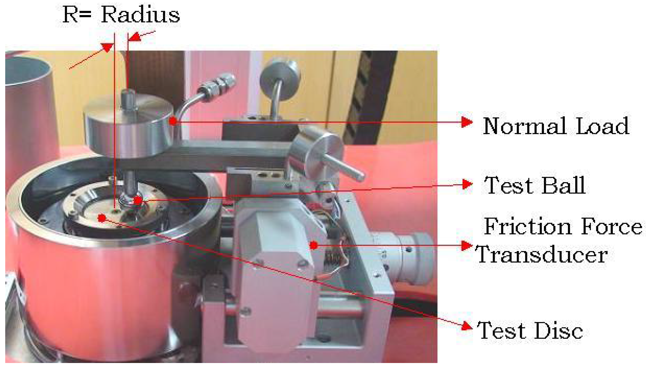
A ball similar to the ones used in the bearing was used for this test. The disc was manufactured from similar material (AISI52100 or EN31). A hole was made in the ball using the EDMtechnique, so that it could be assembled to a shaft. The roughness of the disc was 0.07 μm (Ra). The roughness of the ball was 0.03 μm (Ra). They were measured using the Carl Zeiss Surfcom 1800D.
The ball and the disc were ultrasonically cleaned with acetone. The CSMtribometer was calibrated for frictional force before the tests using a standard procedure. The disc is assembled to the main motor, and the ball with the shaft is then assembled to the frictional force arm (see
Figure 1). A small quantity of lubricant is smeared on the disc. Normal load is applied using weights. The data acquisition (DAQ) is used to acquire real-time coefficient of friction. The normal load, speed and runtime are input parameters to the DAQ software. A typical test in the current work was run for 5 min.
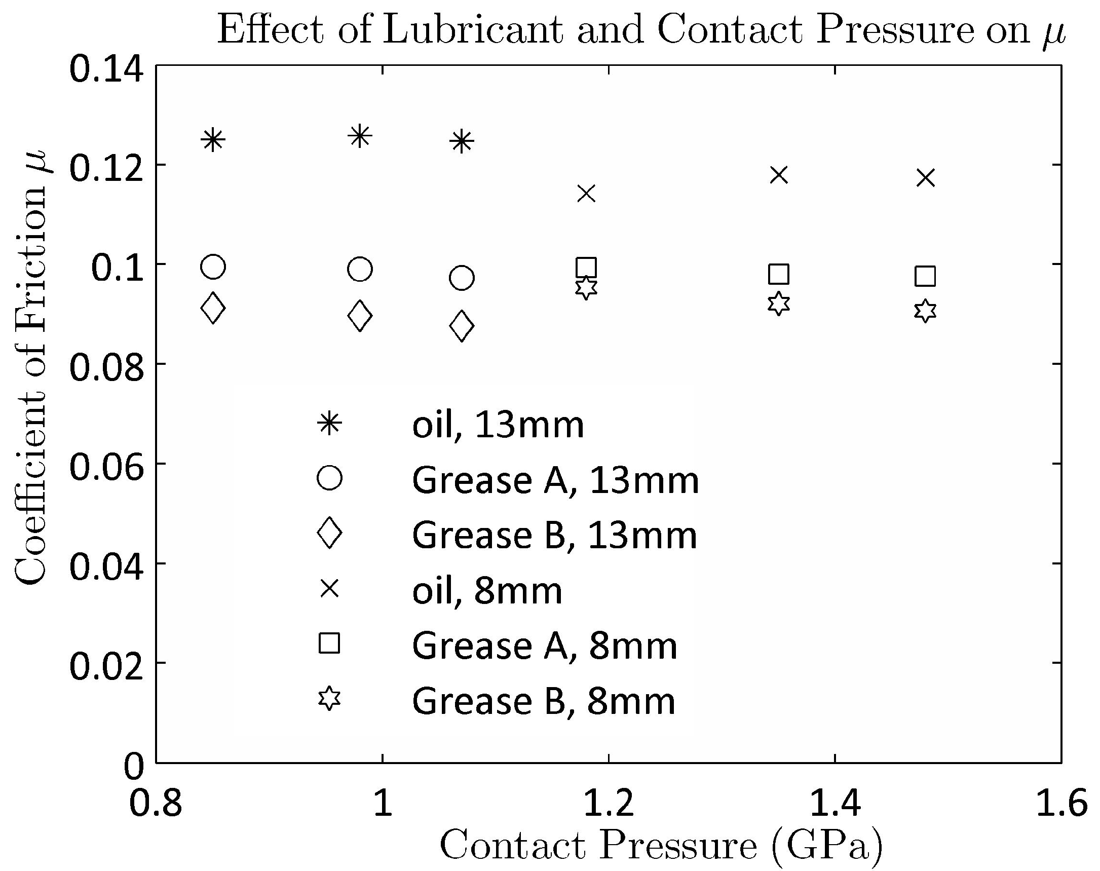
In the current work, the contact pressure was varied from 0.85 to 1.5 GPa, whereas the speed was kept constant at 0.01 m/s.
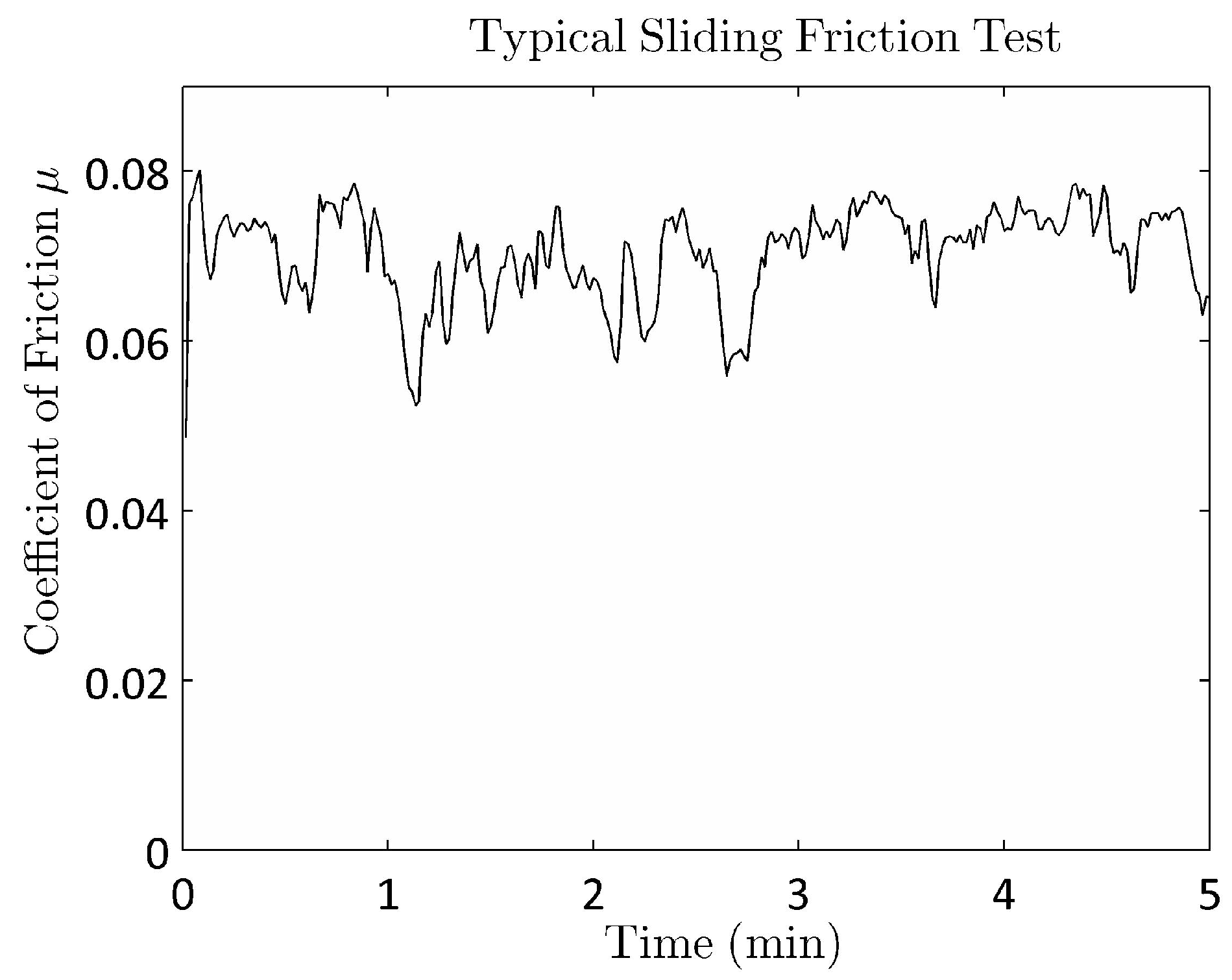
Figure 2 shows a typical test result from the ball-on-plate tribometer at 1.07 GPa contact pressure.
Figure 3 summarizes some test results where the contact pressure and lubricant type were varied at a constant speed of 0.01 m/s. The oil used in this investigation has the highest coefficient friction. There was a significant difference observed between the two greases. The differences are probably due to the difference in viscosity of the base oil. Two ball diameters (8 mm 13 mm; see
Figure 3) had to be used to get the pressure range from 0.85 to 1.5 GPa.
Figure 1.
CSM tribometer used to measure the coefficient of friction.
Figure 1.
CSM tribometer used to measure the coefficient of friction.
Figure 2.
Typical coefficient of friction measured during a lubricated test.
Figure 2.
Typical coefficient of friction measured during a lubricated test.
Figure 3.
Effect of lubricant and contact pressure on the coefficient of friction.
Figure 3.
Effect of lubricant and contact pressure on the coefficient of friction.
3. Formulation of Current Rolling Friction Model
The geometry and the kinematics of the double-arched ball bearing are taken from [
1]. As the current work focuses on the high load-low speed applications, the gyroscopic and centrifugal effects are negligible. The formulation presented in this paper is therefore simplified by ignoring the high-speed effects. In the present work, the ball kinematics problem and the load distribution problem are decoupled and solved separately. This approach makes the torque calculation simpler, and the torque contribution of each ball can be estimated without considering the effects of other balls.
In the current approach, the bearing is first solved for the contact forces and the contact angles at each ball raceway interface using the approach mentioned in Amasorrain
et al. [
5]. Therefore, the contact forces
,
,
and
and the contact angles
,
,
and
are known
a priori and serve as input to the solution of the ball kinematics. Furthermore, due to the slow speed assumption, the inertia forces and moments associated with the gyroscopic and centrifugal effects are assumed to be zero. Moreover, due to the same assumption,
,
,
and
; therefore, the angle
β in Jones [
2] and the angle
in Leblanc and Nelias [
1] will tend to zero.
Taking the above assumptions into consideration, the internal kinematics of each ball is then governed by the effective rolling radii
,
,
,
, and the attitude angle given as
α in [
2] and angle
β in [
1]. Furthermore, all of the four effective rolling radii are not independent. Rolling radii for one set of contacts (inner left-outer right or inner right-outer left) are related to the other sets of contacts through the ratio of angular velocity of the ball about its center to relative angular velocities of outer and inner races
. Therefore, the kinematics of each ball is governed by only three parameters—two rolling radii, either
or
, and the attitude angle.
The moment and force equilibrium of the ball are written as follows:
The simultaneous solution of Equations (
1)–(
3) results in the equilibrium kinematics of each ball. A globally convergent Newton-Raphson iterative procedure described by Press
et al. [
20] is used to solve this nonlinear system with a numerical computation of the Jacobian. The resulting moments and forces can be used to calculate the torque acting at the inner and outer race of the bearing as follows:
Equations (
4) and (
5) represent the torque contribution of every ball to the bearing torque. If the ball is in equilibrium, these values are typically the same. To calculate the torque needed to turn the bearing, the calculated torque of all of the balls needs to be summed up.
Although the current study and the model development are focused on high loads and low speeds, the bearing is still expected to run under either full EHLor a mixed EHL regime. It is therefore assumed that the rolling elements will operate under lubricated rolling-sliding conditions, and the effects of the stick-slip regime have not been considered. For conciseness, the theoretical model is not repeated here. For more details on the model, the reader may refer to the above-mentioned papers.
4. Model Results and Comparison with the Literature
The last section described in detail the kinematics of a four-point contact bearing. Since centrifugal and gyroscopic effects have been neglected, a comparison with data from the literature was possible for two distinct cases:
- (a)
the case when only one out of the two contact lines in the four-point contact bearing is active, effectively creating a two-point angular contact bearing,
- (b)
a case where both the contact lines in the four-point contact bearing are active.
For Case (a) above, a comparison is done with the three cases listed in Todd and Johnson [
6,
7]. As regards Case (b), a comparison is done by comparing the results obtained from the developed model with the code developed by Leblanc and Nelias [
1]. A comparison with the results listed in Hamrock [
3] is not considered, since Hamrock describes a three-point contact bearing configuration that becomes three-point due to centrifugal effects at high speeds of rotation.
Case (a): Comparison of two-point contact bearing results with Todd and Johnson [
6] and Todd [
7].
Table 1 lists the bearing dimensions used in Todd and Johnson [
6] and Todd [
7] for completeness. The above-mentioned data were used to calculate the running torque of each bearing, and the results so obtained were compared with the experimental, as well as analytical running torques published in Todd and Johnson [
6] and Todd [
7]. The summary of the results obtained is shown in
Table 2. It can thus be clearly observed that the results predicted by the current model are very close to the experimental results published by Todd and Johnson [
6] and Todd [
7]. The model also captures the relative order of importance of the torque components. Thus, in the FAG, case the roll component is the most dominant component of the torque according to Todd and Johnson [
6] and Todd [
7], and the model depicts that well. The same is true for the ED20and the EX50case, although the roll component is overestimated. It should be noted that hysteresis is ignored in the current model and is hence shown by a zero. In short, the model compares well with the results published for slow rotating bearings.
Table 1.
Ball bearing data.
Table 1.
Ball bearing data.
| Parameters | FAG | ED20 | EX50 |
|---|
| Ball diameter (mm) | 4.76 | 7.14 | 9.52 |
| PCD(mm) | 88 | 31 | 65 |
| Contact angle (°) | 30 | 15 | 25 |
| Conformity no. | 1.045 | 1.14 | 1.03 |
| Coef.of friction (μ) | 0.12 | 0.12 | 0.1 |
| No. of balls (Z) | 3 | 3 | 3 |
| Load (N) | 400 | 600 | 400 |
Table 2.
Results and comparison with Todd and Johnson [
6] and Todd [
7] (×10
−4 N ·
m).
Table 2.
Results and comparison with Todd and Johnson [6] and Todd [7] (×10 −4 N ·m).
| | | Torque Components | Total | Exp. |
|---|
| Spin | Roll | Hysteresis |
|---|
| FAG | Todd and Johnson [6] | 11.5 | 75.0 | 3.5 | 90.0 | 95 |
| Todd [7] | 10.5 | 69.0 | 3.5 | 83.0 | 74 |
| Present | 10.7 | 83.9 | - | 94.7 | - |
| ED20 | Todd and Johnson [6] | 60.0 | 04.0 | 4.0 | 68.0 | 75 |
| Todd [7] | 64.0 | 05.0 | 4.0 | 73.0 | 78 |
| Present | 54.4 | 15.9 | - | 70.3 | - |
| EX50 | Todd and Johnson [6] | 39.0 | 15.0 | 2.0 | 56.0 | 66 |
| Todd [7] | 39.0 | 15.0 | 2.0 | 56.0 | 80 |
| Present | 37.1 | 27.0 | - | 64.1 | - |
Case (b): Comparison of four-point contact bearing results with the model presented in [
1].
Unlike Case (a), where already published experimental and analytical results were readily available for slow rotating two-point angular contact bearings, getting readily published results for slowly rotating four-point contact bearings was a challenge. It was thus decided to test the model results with results obtained from a code developed at INSALyon by Leblanc and Nelias [
1]. The bearing properties used for the comparison are listed in
Table 3.
Table 3.
Bearing properties for code comparison.
Table 3.
Bearing properties for code comparison.
| Properties | Value |
|---|
| No. of balls | 156 |
| Ball diameter (mm) | 35 |
| Initial contact angle (°) | 45 |
| Conformity ratio | 1.05 |
| Interference at each contact (μm) | 7.6 |
| PCD (m) | 1.9 |
Interference is assumed at each contact location to ensure that a four-point contact is obtained in most circumstances. The concept of interference as explained in Amasorrain
et al. [
5] is being shown here in
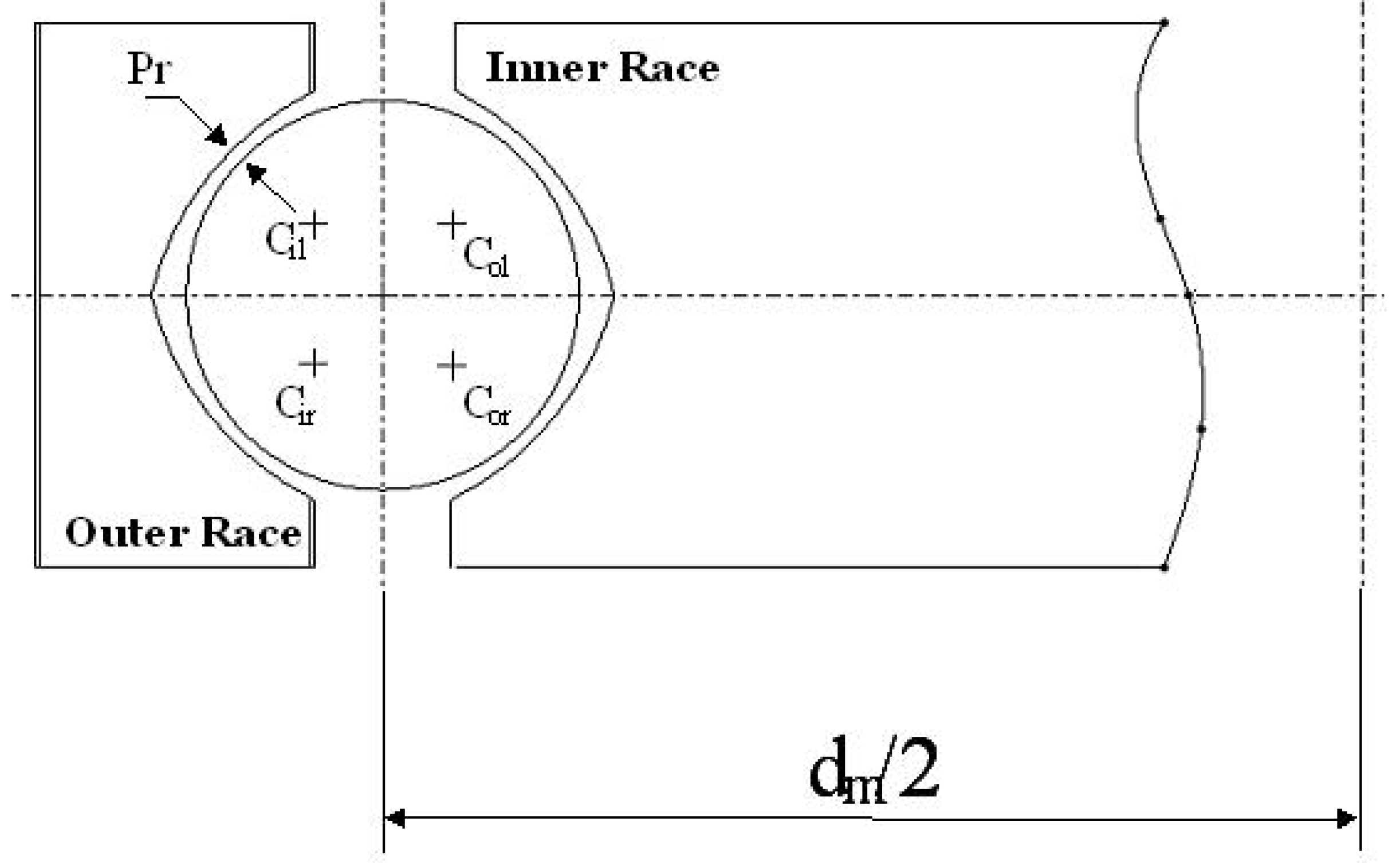
Figure 4, again for completeness. It should be noted that
Figure 4 shows a bearing with a clearance. For a bearing with interference, the ball is actually bigger than the cavity; thus,
Pr, as shown in
Figure 4, will be negative. Loads listed in
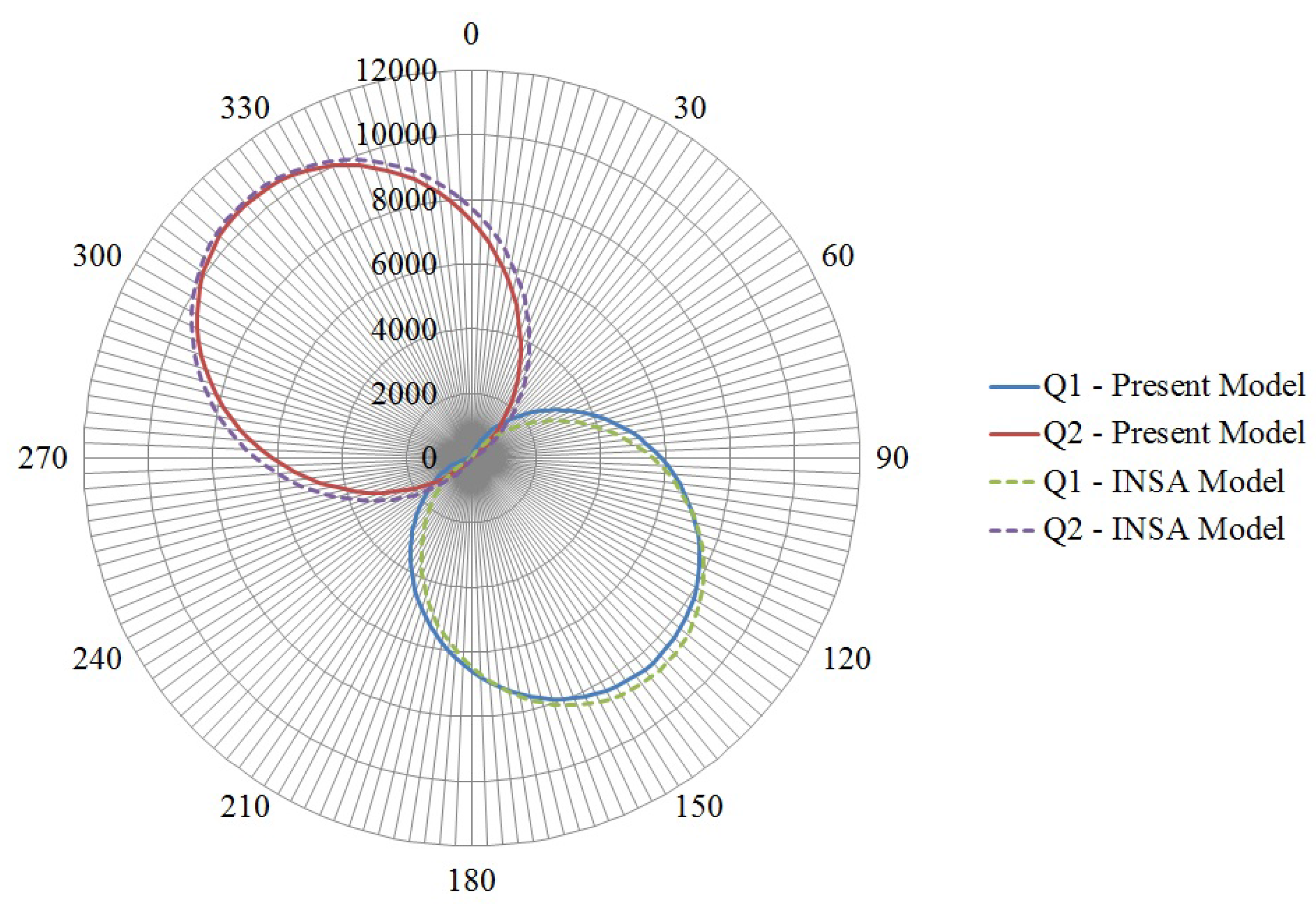
Table 4 were applied at the center of the bearing. The load distributions using the current model and the one developed by Leblanc and Nelias [
1] were compared, and the comparison showing loads in Newton is depicted in
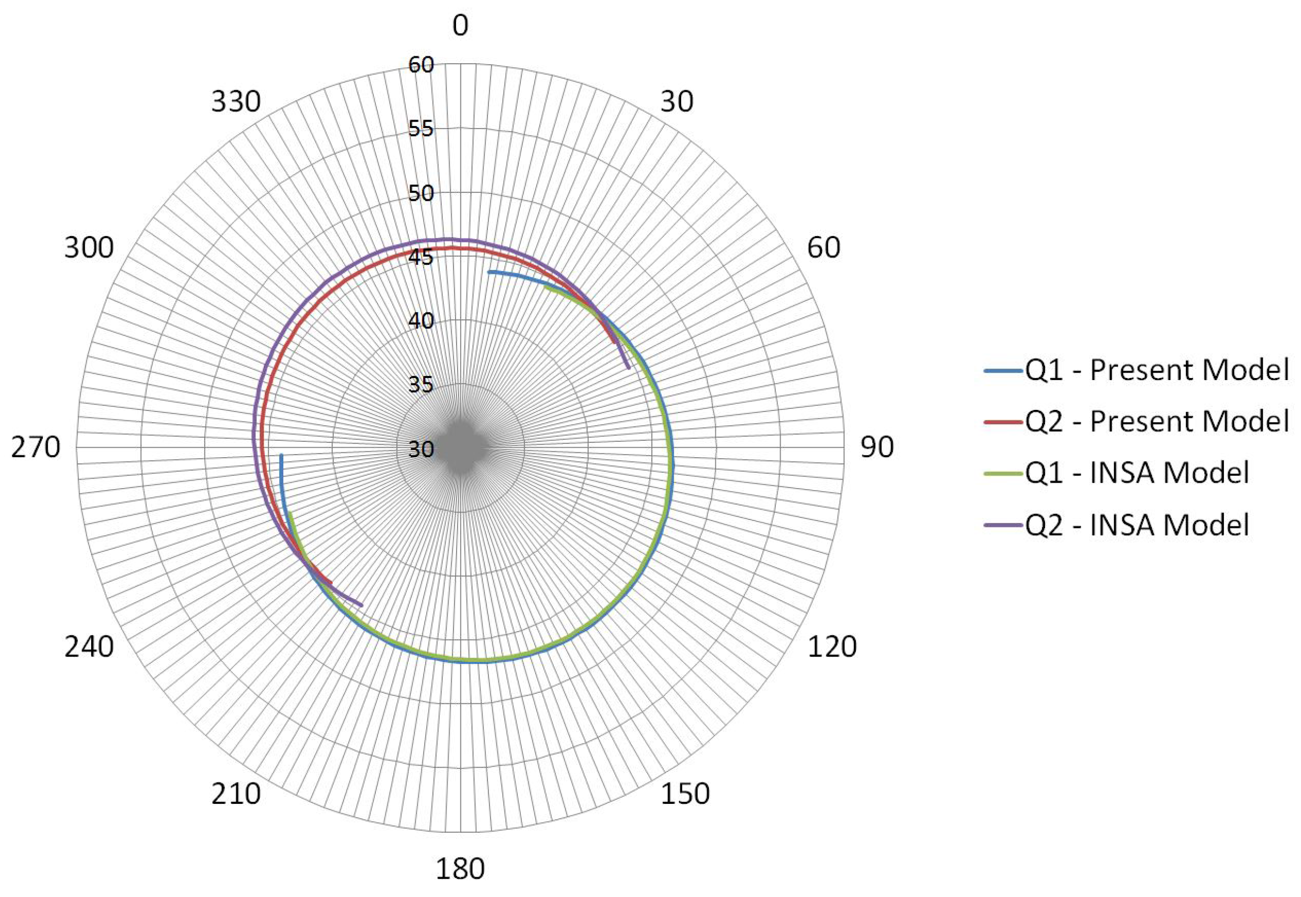
Figure 5. The similar comparison for contact angle is depicted in
Figure 6. As can be seen, the two models give similar results. The maximum difference between the two models was seen to be 8% for loads and less than 2% for contact angles.
Figure 4.
Concept of interference.
Figure 4.
Concept of interference.
Table 4.
Loads applied to the bearing.
Table 4.
Loads applied to the bearing.
| Loads | Value |
|---|
| Fx (N) | 36,200 |
| Fy (N) | −31,400 |
| Fz (N) | 0 |
| Mx (Nm) | −328,601 |
| Fy (Nm) | −378,833 |
Figure 5.
Load distribution comparison.
Figure 5.
Load distribution comparison.
Figure 6.
Contact angle distribution comparison.
Figure 6.
Contact angle distribution comparison.
Torque values were also calculated from both the models, and the values were found to be 1080.0 N·m and 1005.2 N·m, respectively. It can thus be claimed that the two models are indeed comparable.
5. Experimental Setup, Test Procedure and Results
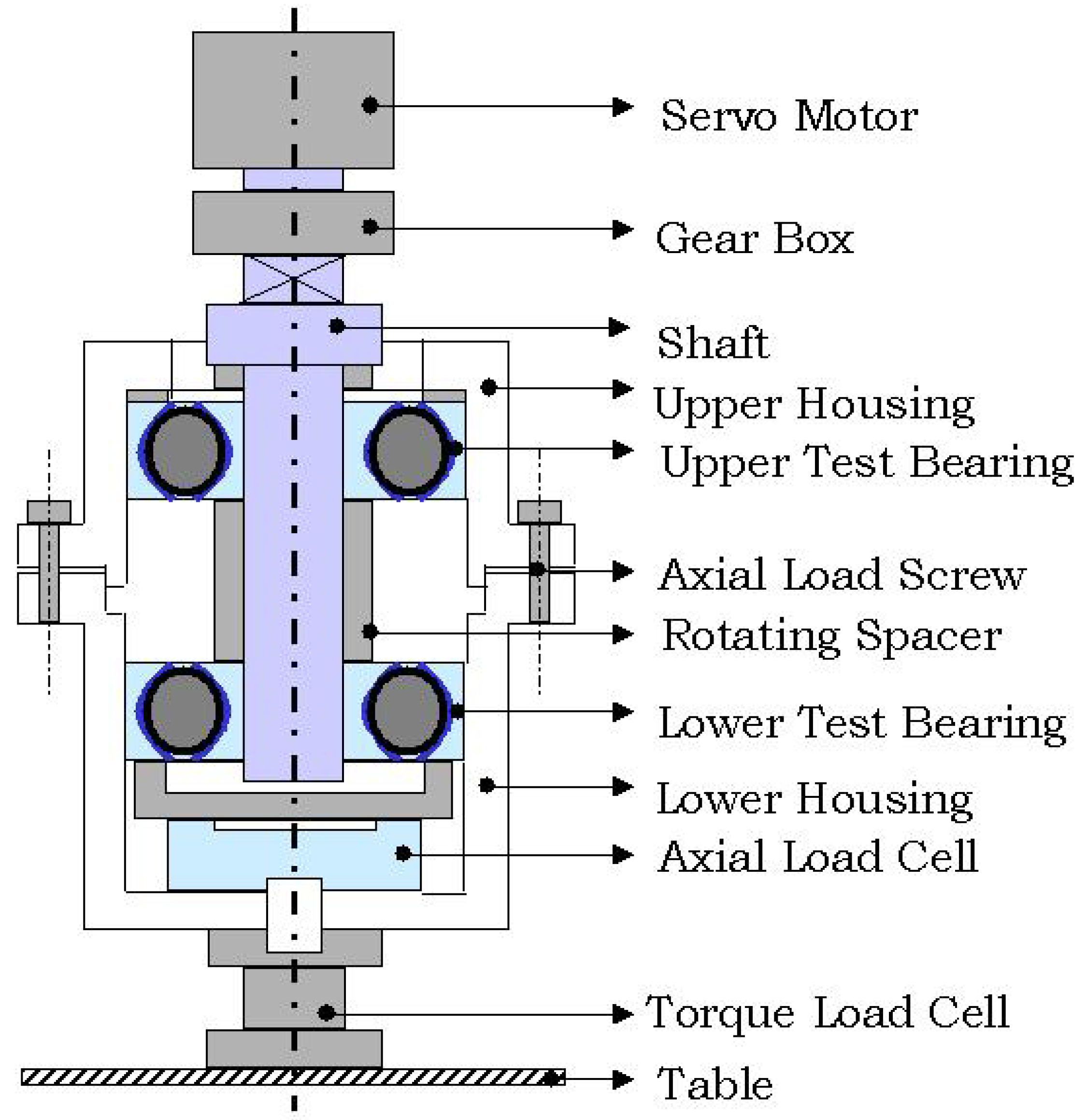
Figure 7 summarizes the features of the low-speed friction torque rig (FTR). The shaft is driven using a servomotor. The two bearings are assembled in such a way that an axial load is applied between them by tightening the six axial load screws (
Figure 7). The bearing cartridge, which consists of the two bearings and the axial load cell, is then connected to the test table through the torque transducer. The torque transducer measures the torque in real time.
Figure 7.
Schematic of the low-speed friction torque rig (FTR).
Figure 7.
Schematic of the low-speed friction torque rig (FTR).
The specifications of the FTR can be summarized as follows:
Bearing types: angular contact and four contact-point bearings
Bearing diameter: 50 to 100 mm
Rotation: CWand CCW(1 to 50 rpm)
Oscillation: 10° to 90° (CW and CCW) with 0.6-Hz speed
Axial load: 1 to 100 kN
Max. friction torque: 110 N·m
The bearings (balls and races disassembled) are cleaned using an ultrasonic cleaner with acetone. The ball diameter, groove radius and the distance between two races (for a four-point contact bearing) is measured using a Carl Zeiss Surfcom 1800D. The surface roughness of the ball and the grooves are also measured using the same instrument.
The bearings are then filled with the required lubricant (oil or grease). Bearings are then assembled to the shaft, after which, the shaft is assembled to the housings (upper and lower) with the axial load cell in the bottom (of the shaft). The housings are then connected to the gearbox at the top and the torque cell at the bottom. It is ensured that the axial load cell and torque cell read zero. Axial load is then applied by tightening the six screws. The opposite screws are tightened in sequence to ensure uniform loading.
The custom-built DAQ is used to acquire real-time torque, axial load and speed data. After applying the required axial load, the speed and test run-time are set in the DAQ. In the current work, the tests were performed for duration of 5 min (only rotation).
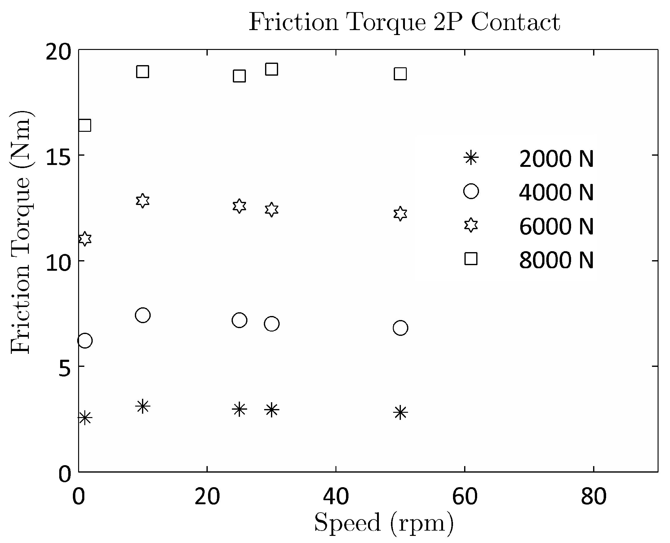
Figure 8 shows a typical test (two-point contact) result from the low-speed FTR at different loads and speeds. The effect of speed can be seen to be marginal for the two-point contact and will be ignored hereafter.
Figure 8.
Typical two-point contact test results from the FTR at different axial loads and speeds.
Figure 8.
Typical two-point contact test results from the FTR at different axial loads and speeds.
6. Comparison against Experimental Measurements
Tests were done using the FTR described in the last section on two FAG QJ309 bearings. These are split inner race bearings. There were two parts to the tests performed.
- (a)
Tests on bearings mounted using a clearance
- (b)
Tests on bearings mounted using larger-sized balls to obtain an interference
All tests were done typically at two speeds, and only a marginal effect of speed was found. The bearing data used for calculations are shown in
Table 5:
Table 5.
Bearing Data.
| Geometry | Value |
|---|
| No. of balls (Z) | 10 |
| Ball diameter (mm) | 18.25 |
| PCD (mm) | 72.38 |
| Inner race conformity | 1.033 |
| Outer race conformity | 1.061 |
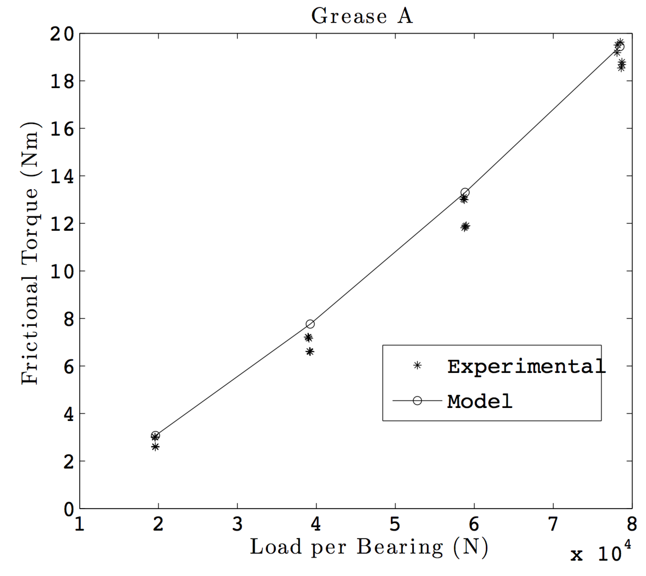
Case (a): Tests were performed at various loads and at two speeds. As mentioned earlier, the speed effect was marginal, and hence, the results for various speeds were combined. Tests were also done using different greases. The results obtained from such tests were compared against the results obtained from the model. The coefficient of friction obtained in the tests described in
Section 2 was used for the calculations.
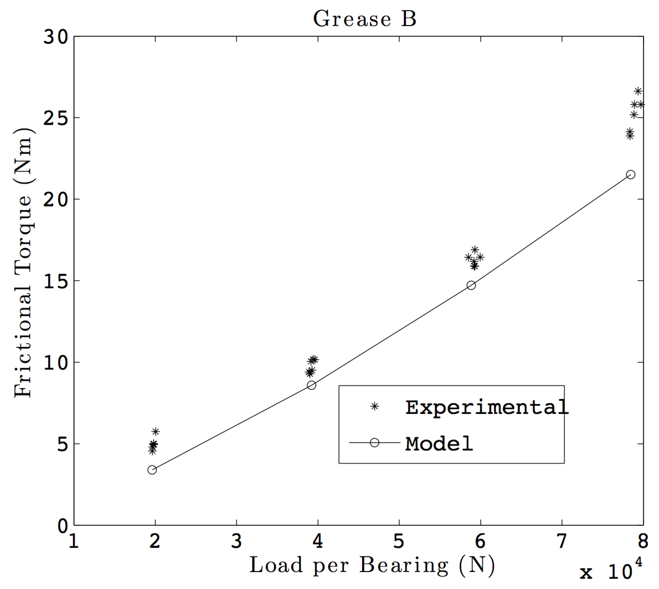
Figure 9 shows such a comparison for Grease A, while
Figure 10 shows such a plot for Grease B. The maximum difference between the model and the experiments done for Grease A is observed to be 15.6%. This difference is 69% for testing done with Grease B and is observed at low loads, where the measured torque values are in the lower end of the torque cell measuring range. The RMS differences for Grease A and Grease B are 9% and 29%, respectively. The larger difference at the lower loads can be partially explained by the uncertainty in measuring the clearance in the bearing, which governs the kinematics of the bearing. Note that the values reported are for two bearings together.
Figure 9.
Model vs. test results with Grease A.
Figure 9.
Model vs. test results with Grease A.
Figure 10.
Model vs. test results with Grease B.
Figure 10.
Model vs. test results with Grease B.
When a four-point angular contact bearing is mounted with a clearance and loaded in a purely axial fashion, the bearing behaves like a two-point (angular) contact bearing. Thus, only one contact line participates in the load transfer. The results above demonstrate that the model is able to calculate torque accurately in the two-point contact mode.
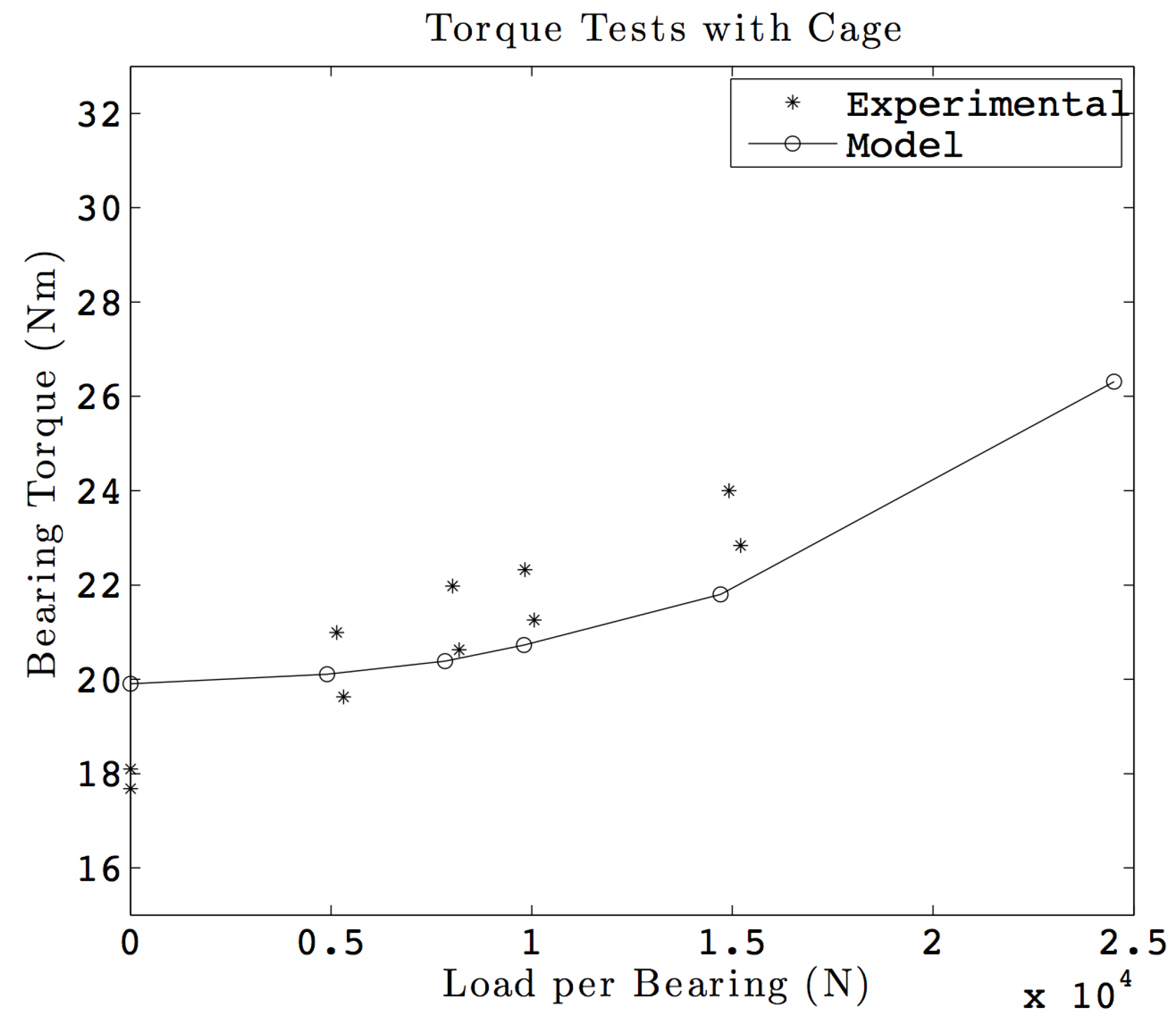
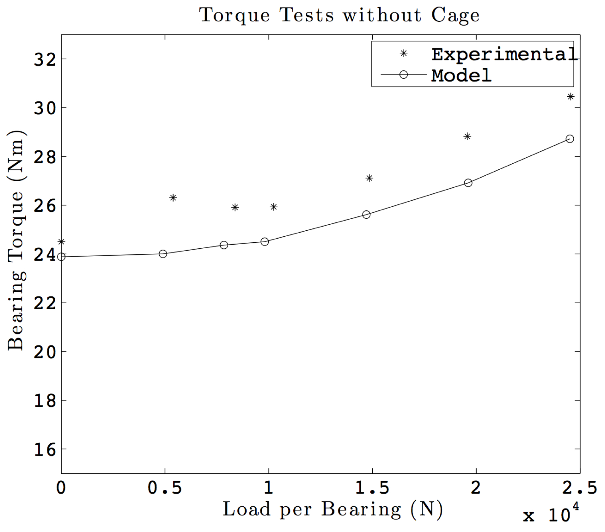
Case (b): Generating interference in a split inner race four-point angular contact bearing is indeed a challenge. To start with, a reasonably accurate estimate of the diametral play needs to be established. The ball size then needs to be increased, so as to obtain interference in the bearing. The interference obtained depends on how close the two inner races can be brought together. In our case, the ball size was increased to 18.32 mm for the same QJ309 bearing. Having obtained a reasonable estimate of interference, tests similar to Case (a) were repeated. Two sets of tests were done: (1) with a cage; and (2) without a cage.
Figure 11 shows the torque comparison when the cage was used. The maximum and the RMS difference observed in this case are found to be 11.2% and 7.0%, respectively.
Figure 12 shows a similar plot for tests without a cage. The maximum and the RMS difference observed in this case are found to be 7.1% and 6.5%, respectively. This shows that the test and the model results are in close agreement with each other. It is interesting to note that the friction torque without the cage is significantly higher than the one with a cage. This can be explained by the internal kinematics for an oscillatory movement: while the ball spacing remains constant with a cage, interactions between adjacent balls can be observed for the bearing without the cage, thus increasing the friction torque. It should be noted that no cage dynamics was modeled while calculating the bearing torque, and hence, the details of the cage design are not being given.
Figure 11.
Bearing torque comparison for tests with a cage.
Figure 11.
Bearing torque comparison for tests with a cage.
Figure 12.
Bearing torque comparison for tests without a cage.
Figure 12.
Bearing torque comparison for tests without a cage.
7. Conclusions
A comprehensive model for calculating the load distribution, the internal kinematics and then the friction torque of a slow-speed, four-point contact bearing was developed. This model was validated with results obtained by other authors and available in the literature. The measurement of the friction coefficient for different lubricants, performed on a ball-on-plate tribometer, has been used as input data for the bearing torque calculation. A test set-up, called friction torque rig (FTR), that runs at slow speeds was developed to take on pure axial loads, and bearings were tested with clearance and with interference. Experimental data have been obtained for two-point contact and four-point contact bearings, with and without a cage. The test results so obtained were compared with the results from the model, and the model was found to be in good agreement with the experiments. Interestingly, it was observed experimentally and also confirmed numerically that the presence of a cage permits one to lower the friction torque of a four-point contact ball bearing.


