1. Introduction
Liquid rocket turbopumps operate under extreme cryogenic, high-speed, and high-pressure conditions, and the reusable service requirement places increasingly stringent demands on the sealing stability, leakage control, and tribological performance of mechanical seals. During operation, the end-face seals are prone to liquid film instability, frictional wear, and leakage increase, especially under large pressure differences and low-speed operating conditions. Therefore, improving the hydrodynamic pressure generation capacity and leakage suppression ability of mechanical end-face seal structures is of great significance for enhancing the reliability and service life of turbopump sealing systems.
At present, extensive studies have been carried out on the structural optimization and performance improvement of hydrodynamic mechanical seals. Meng et al. [
1] conducted numerical analysis on turbopump hybrid hydrodynamic–hydrostatic mechanical seals, while Tao et al. [
2] developed matched bearing and sealing structures for reusable turbopumps. As an effective method for improving liquid film pressure and reducing end-face contact, groove structures have been widely used in mechanical seal design [
3]. Existing studies have investigated various groove forms, including spiral grooves, porous grooves, micro-textures, bionic grooves, and composite groove structures. Badykov et al. [
4] established dynamic models for turbomachinery mechanical seals and pointed out that a reasonable end-face groove layout is essential for stable operation and leakage control. Wang et al. [
5,
6] systematically summarized structural optimization methods for hydrodynamic mechanical end-face seal grooves. Zhang et al. [
7] established a two-phase flow theoretical model for low-temperature high-speed spiral groove seals and carried out bench tests. Li et al. [
8,
9] studied porous–spiral groove composite structures and revealed the influence of groove–texture coupling on liquid film bearing capacity and heat-mass transfer. In addition, stepped, micro-textured, and bionic groove structures have also been proposed to improve lubrication stability, leakage control, and wear resistance [
10].
Although these studies have effectively promoted the development of groove-type mechanical seals, conventional single-depth groove structures still show certain limitations under cryogenic high-speed operating conditions [
11]. The single convergent wedge formed by ordinary grooves provides limited hydrodynamic pressure, resulting in insufficient liquid film load-carrying capacity, narrow high-pressure regions, and uneven pressure distribution [
12]. Meanwhile, the lack of multi-stage throttling channels makes it difficult to effectively suppress radial leakage under high rotating speed and large pressure differences [
13]. During low-speed operation, the weak hydrodynamic effect may also lead to unstable mixed lubrication, increased friction coefficient, and aggravated end-face wear [
14]. Therefore, it is necessary to develop a groove structure with stronger pressure-generation ability, better leakage suppression performance, and improved lubrication stability [
15].
To address the above problems, this paper proposes a stepped-groove mechanical seal structure by introducing step-depth variation into the sealing end-face groove [
16]. The stepped configuration transforms the original single-flow channel into a multi-stage convergent flow channel, thereby strengthening the hydrodynamic wedge effect and improving the pressure build-up capacity of the liquid film [
17]. Compared with conventional straight and standard spiral grooves, the stepped groove can expand the high-pressure region, increase the liquid film opening force, and enhance the throttling effect on radial leakage [
18]. In addition, the stepped structure is beneficial for retaining more lubricant in the groove region during low-speed operation, which helps to stabilize mixed lubrication and reduce friction fluctuation.
In this study, Fluent numerical simulation and friction-wear tests are carried out to investigate the sealing and tribological performance of stepped-groove mechanical seals [
19]. The pressure distribution, liquid film opening force, leakage rate, friction coefficient, and wear characteristics of different groove structures are compared. Furthermore, the influence of key stepped-groove parameters on sealing performance is analyzed to determine the optimal structural scheme. The results of this work can provide theoretical and experimental guidance for the design and optimization of mechanical seals used in liquid rocket turbopumps.
This numerical model only calculates the hydrodynamic liquid film flow field, and the thermal deformation of the sealing ring is not included in the current simulation. The present study focuses on the hydrodynamic sealing performance of different groove configurations, with particular emphasis on the liquid film opening force and leakage rate. Therefore, to isolate the influence of groove geometry and maintain consistent comparison conditions, the sealing faces are assumed to remain rigid, and the thermo-mechanical deformation of the sealing rings is not coupled into the current CFD model. It should be noted that thermal deformation may alter the local film clearance and consequently affect the sealing performance. Its influence on film-thickness distribution, opening force, and leakage will be systematically investigated through thermo-fluid–solid coupling analysis in future work.
Section 2 clarifies the research motivation via preliminary tribological comparison, comparatively analyzing the friction coefficient and fluctuation characteristics of the stepped groove, spiral groove, and line groove under mixed lubrication during low-speed processes.
Section 3 describes the theoretical model, including the geometric configuration, basic assumptions, governing equations, boundary condition settings, and verification of the numerical model.
Section 4 presents the numerical simulation results and discussion, comparatively analyzing the liquid film pressure distribution, the effects of operating and structural parameters on sealing performance, and the tribological characteristics of the stepped groove, spiral groove, and line groove. Finally,
Section 5 summarizes the main conclusions of this work, providing a reference for the optimal design of groove types.
2. Preliminary Comparison and Research Motivation
Besides insufficient liquid film load-carrying capacity under high-speed, high-pressure conditions, mechanical seals may experience aggravated frictional wear under low-speed operating conditions, where mixed lubrication and weak hydrodynamic effect fail to maintain full-face separation. End-face groove geometry directly governs film formation and friction stability and is critical to the service reliability of turbopump seals.
To preliminarily validate the tribological superiority of the proposed stepped groove structure and justify the research motivation, comparative friction tests were performed on three typical groove configurations: line groove, spiral groove, and stepped groove. Using a graphite pin-on-hard-ring friction pair under oil-bath lubrication, tests were carried out at two rotational speeds (200 and 400 r·min−1) and two normal loads (10 and 20 N) to comparatively evaluate the tribological behavior of different groove configurations under low-speed steady-state conditions.
The results demonstrate that all three groove types experience a brief run-in period before reaching a steady friction state. The stepped groove consistently achieves the lowest friction coefficient and the smallest fluctuation amplitude across all test conditions, showing remarkable advantages over the spiral groove and line groove. Specifically, under the 400 r·min−1 and 10 N condition, the stepped groove forms a more stable lubricating film with enhanced hydrodynamic pressurization, which effectively mitigates direct asperity contact between the sealing end faces.
This preliminary experimental evidence indicates that the stepped-groove structure not only improves liquid film bearing capacity in theory but also exhibits favorable tribological performance under low-speed operating conditions. Building on this finding, this paper systematically investigates the increase in rotational speed and the leakage rate of the three groove types all exhibit an upward trend, while the opening affects the sealing mechanism and performance of the stepped-groove mechanical seal through numerical simulation, supplemented by a qualitative tribological comparison under simplified laboratory conditions.
3. Theoretical Model
3.1. Geometric Model
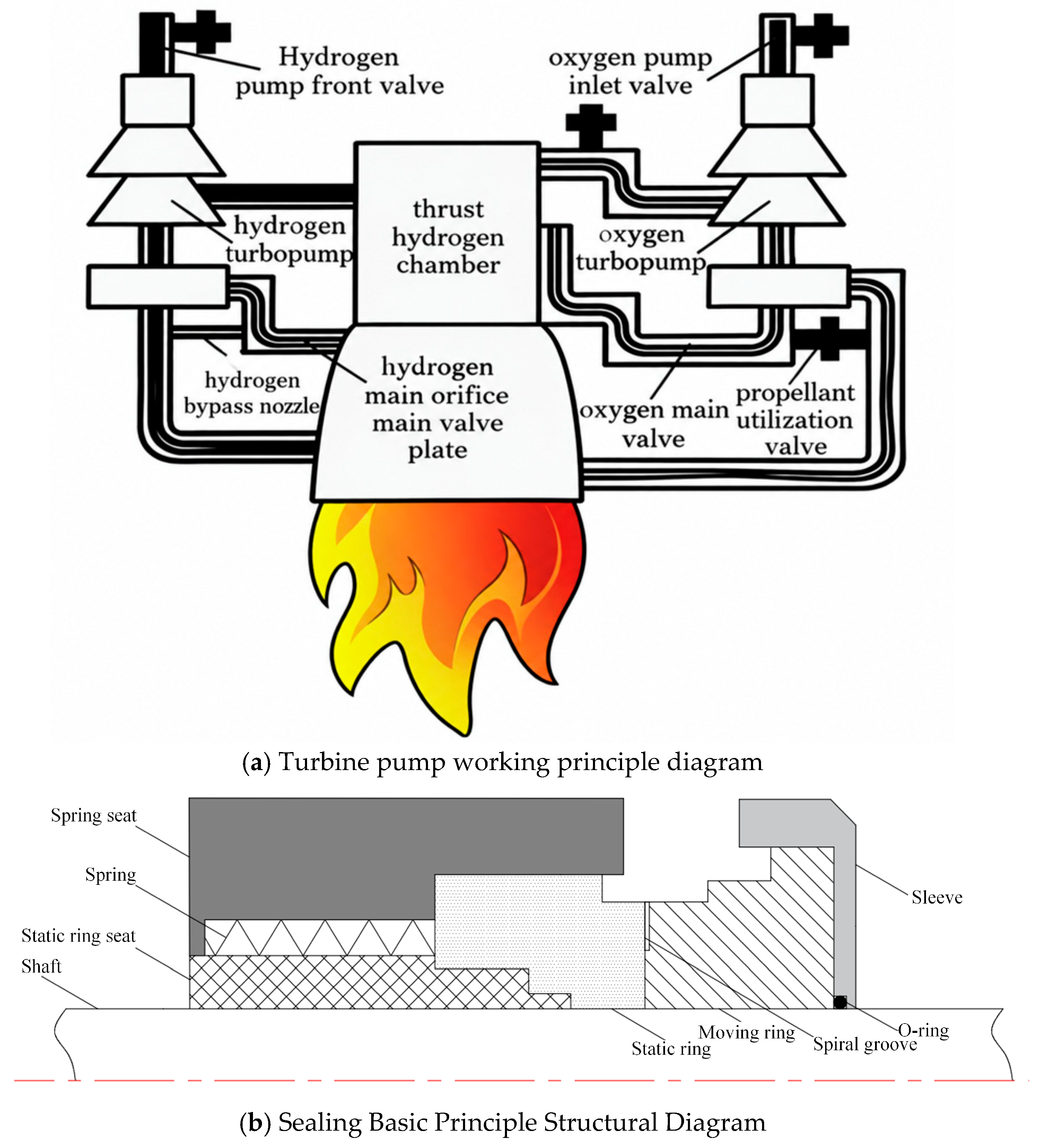
Figure 1a shows the schematic diagram of the rocket engine turbopump. The main function of the turbopump is to deliver the propellant to the main thrust chamber, where high-speed gas flow is generated and expelled through the nozzle to produce thrust.
Figure 1b shows the structural diagram of the mechanical seal of the turbopump. The groove depths of the first and second step channels are defined as hg
1 and hg
2, respectively. In the present stepped-groove configuration, the first-step groove depth is hg
1 = 4 μm, while the second-step groove depth is hg
2 = 8 μm, thereby forming a two-stage convergent flow channel from the deep-groove region to the shallow-groove region.
In the baseline stepped-groove configuration, the first-step groove depth hg1 is fixed at 4 μm, while the second-step groove depth hg2 is set to 8 μm. In the groove-depth parametric study, hg1 remains constant at 4 μm, whereas hg2 is varied from 6 to 14 μm and is denoted by hg for convenience. Therefore, hg = 8 μm corresponds to the baseline configuration with hg1 = 4 μm and hg2 = 8 μm.
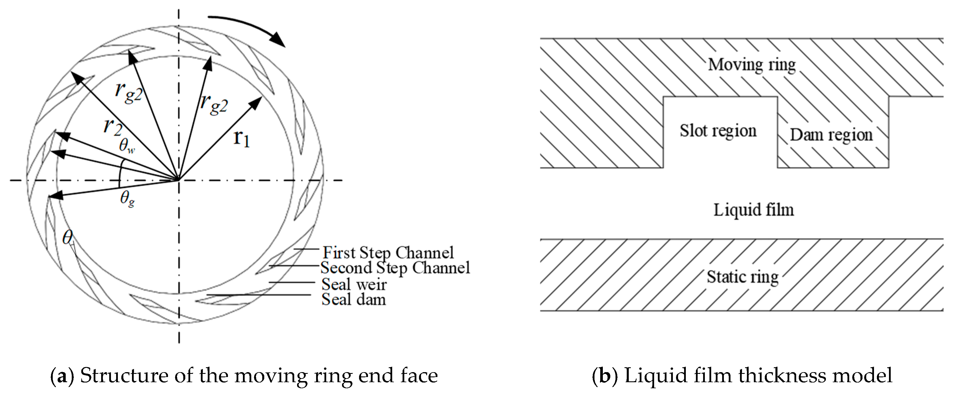
This study considers three groove types, namely the line groove, spiral groove, and stepped groove. The stepped groove can be regarded as a composite groove configuration that combines the structural characteristics of both the line groove and the spiral groove. To ensure consistency in the comparative analysis among different groove types, all geometric parameters other than the groove structure are kept identical. These parameters mainly include the inner and outer diameters of the sealing face, groove depth, spiral angle, groove width ratio, groove number, and initial film thickness. The detailed structural parameters are listed in
Table 1, and the physical properties of the sealing medium are presented in
Table 2. The cross-sectional schematic of the stepped groove is shown in
Figure 2a, and the liquid film thickness model is shown in
Figure 2b. Since the flow characteristics of the fluid domain in each periodic section are essentially the same, a single-period liquid film domain is adopted in this study to improve computational efficiency. The groove profile is defined by a logarithmic spiral and is uniformly distributed along the circumferential direction. Its expression is given as follows:
where
is the polar radius, unit: mm;
is the polar angle, unit: °; and
is the spiral angle, i.e., the angle between the tangent to the logarithmic spiral and the tangent to the base circle at the same point, unit: °.
3.2. Basic Assumptions of the Flow Field
The calculation of the flow field is quite complicated. To facilitate the calculation, according to the basic flow field calculation theory, combined with the characteristics of operating conditions and operating parameters, the following assumptions are made.
(1) The sealing medium is treated as a continuous, incompressible Newtonian fluid. Body-force effects are neglected. To evaluate the flow characteristics of the liquid film under different rotational speeds, the local film Reynolds number is introduced as follows:
where
is the density of liquid nitrogen, ω is the angular velocity, r is the local radial position, h is the liquid film thickness, and μ is the dynamic viscosity. Taking the reference film thickness of 8 μm and the outer radius of 50 mm, the Reynolds numbers at 5000, 10,000, 20,000, and 40,000 r·min
−1 are approximately 1049, 2097, 4194, and 8389, respectively. The results show that the Reynolds number increases significantly with rotational speed, indicating that non-laminar effects may become increasingly important under high-speed operating conditions.
(2) The end faces of the moving and static rings are approximately rigid and smooth surfaces, and there is a no-slip boundary condition for the fluid on the solid wall; the effect of surface roughness on the liquid film flow is not considered.
(3) The operation process is treated according to the steady-state condition, and the influence of axial vibration and other transient disturbances on the stability of the flow field is ignored.
(4) In practical high-speed rotating systems, shaft misalignment may occur in the form of parallel or angular misalignment, which may induce radial and axial vibration and lead to relative eccentricity or inclination between the rotating and stationary sealing faces. Such face misalignment can cause circumferential variations in the liquid film thickness and consequently alter the pressure distribution, opening force, and leakage characteristics of the mechanical seal. Previous studies have also shown that relative face deformation and inclination may result in convergent or divergent film-clearance distributions and significantly affect sealing performance. In the present study, the aligned condition is adopted as the reference configuration to isolate the influence of groove geometry, and the rotating and stationary faces are therefore assumed to remain parallel under the comparative operating conditions.
3.3. Governing Equations and Performance Parameters
Since the sealing medium used in the flow field is a continuous, incompressible Newtonian fluid, the fluid governing equations adopted include the continuity equation and the energy equation, which are shown as follows, respectively.
where
and
transferred the heat flux from the flow field to the rotor and stator, W·m
−2;
the average viscous dissipation term, W·m
−3;
Cp specific heat at constant pressure, W·(kg·K)
−1;
and
are the average flow velocity in the direction of x and y, m·s
−1;
is the average temperature in the direction of z, K; and
is the fluid thermal conductivity, W·(kg·K)
−1.
The energy equation is employed to describe thermal transport within the liquid film domain; however, the resulting thermal field is not further coupled with the thermo-mechanical deformation of the sealing rings in the present model.
For the liquid film domains of the three groove types, namely the line groove, spiral groove, and stepped groove, the CFD method is adopted to calculate and analyze their sealing performance parameters. To characterize the hydrodynamic behavior and sealing performance of different groove types, the opening force, leakage rate, and friction force of the liquid film are selected as the main evaluation parameters, and their corresponding calculation formulas are given as follows.
where
is the pressure in the liquid film,
is the area of the end-face seal;
is the mass leakage rate through one periodic computational domain, kg·s
−1;
is the fluid density, kg·m
−3;
is the local fluid velocity vector, m·s
−1; and
n is the outward unit normal vector of the outlet surface. The calculated mass leakage rate is converted to g·s
−1 for presentation in the following results.
According to hydrodynamic lubrication theory, the viscous shear effect within the liquid film is the primary source of friction in the sealing pair. During actual operation, the friction force is also influenced by various factors, including the groove configuration, material properties, and fluid properties. The friction force can be calculated as follows:
where
is the friction force acting on the sealing end face, in N, and
is the shear stress of the liquid film.
3.4. Boundary Condition Setting and Mesh Generation
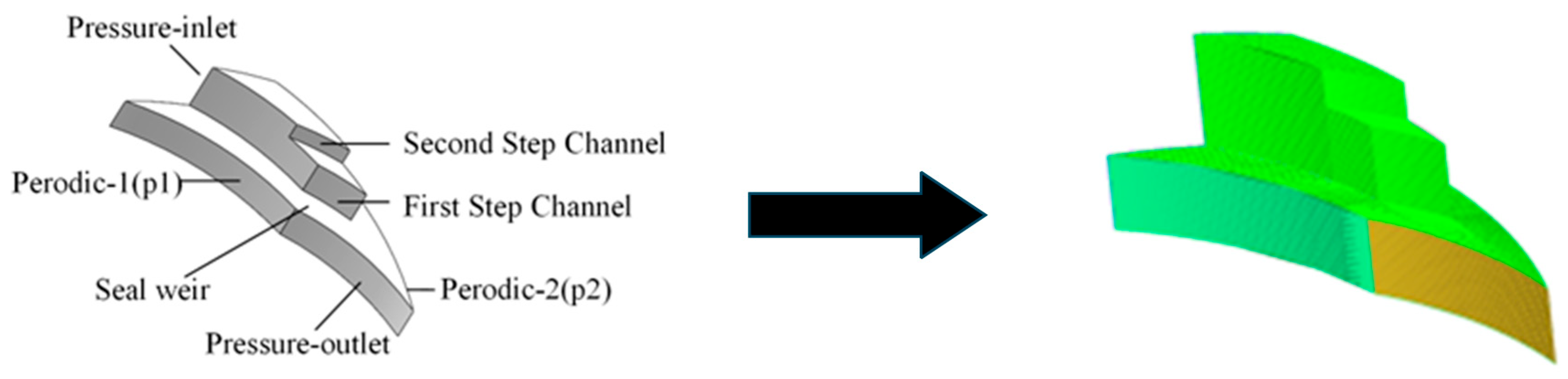
Considering the rotational periodic symmetry of the groove structure in the circumferential direction, the minimum repeating unit of the liquid film domain, i.e., 1/Ng of the full domain, is extracted for numerical analysis. Rotational periodic boundaries are defined in ICEM to reduce the computational cost and improve efficiency. The lower surface of the liquid film is defined as the rotating wall, and the upper surface is defined as the stationary wall, while all other non-characteristic surfaces are treated as no-slip walls. The outer diameter of the fluid domain is specified as the pressure inlet, and the inner diameter is specified as the pressure outlet. In ANSYS Fluent 2022 R2, the reported pressure is defined relative to the operating-pressure reference, while the corresponding absolute pressure depends on both the reported pressure and the operating pressure. Therefore, a negative reported pressure value does not necessarily indicate a physically negative absolute pressure. For liquid nitrogen, the occurrence of cavitation should be evaluated by comparing the local absolute pressure with the saturation vapor pressure at the specified temperature. The two circumferential side surfaces are set as periodic boundaries, p1 and p2, satisfying the pressure periodic boundary condition p(θ + 2π/Ng) = p(θ). Liquid nitrogen is used as the sealing medium, and the inlet temperature is specified as −190 °C according to the operating condition considered in this study. The thermophysical properties of liquid nitrogen listed in
Table 2 are treated as constant values in the present numerical model. Pressure–velocity coupling is solved using the Coupled algorithm. The detailed boundary conditions and periodic settings are presented in
Figure 3. The stepped-groove end face contains two series of flow channels, defined as the first-step primary channel and the second-step secondary channel, as illustrated in
Figure 3. All geometric dimensions of the two channels, such as groove depth, circumferential width, and radial extending length, are quantitatively summarized in
Table 1. The first-step channel corresponds to the front-stage convergent flow region, while the second-step channel is the rear-stage pressure stabilization region, and their distinct dimensional parameters jointly form the multi-stage hydrodynamic boosting effect of the proposed groove.
3.5. Grid Independence and Correctness Verification
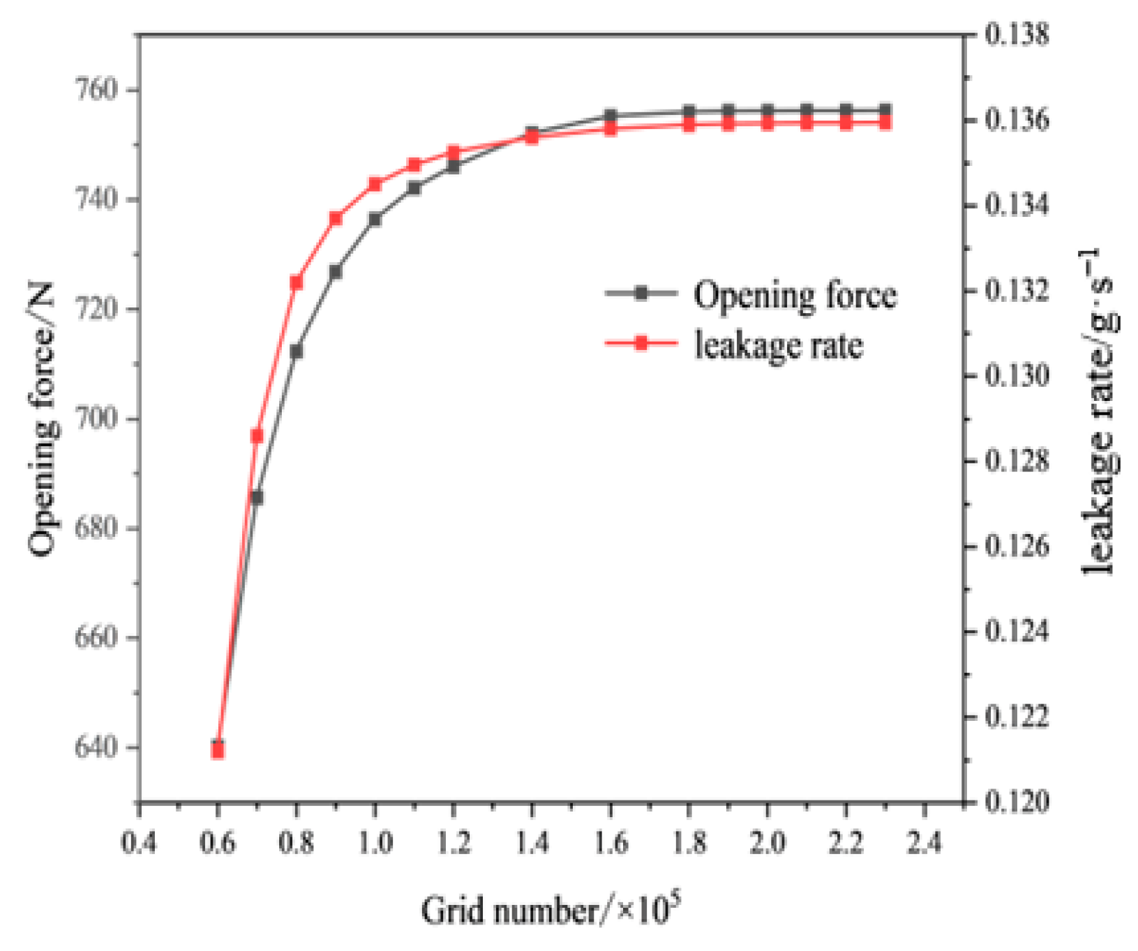
Mesh density introduces discretization errors to the liquid film flow field simulation, so mesh independence verification is essential to exclude the influence of grid quantity on calculation results while balancing computational accuracy and efficiency. Four sets of structured hexahedral meshes with different cell counts (60,000, 100,000, 180,000, and 230,000 cells) were generated for mesh independence analysis. Two core sealing indicators, opening force and leakage rate, were taken as evaluation criteria to quantify the numerical deviation caused by mesh coarseness.
As shown in
Figure 4, opening force and leakage force change sharply when the grid number increases from 60,000 to 100,000, demonstrating that coarse meshes produce large numerical errors and cannot obtain credible flow field results. When the grid quantity reaches 180,000 cells, the variation in the two performance parameters becomes negligible. Further mesh refinement to 230,000 cells only yields relative deviations of 0.028% for opening force and 0.037% for leakage rate, both less than the widely accepted threshold of 0.1%. This proves that the calculation results achieve mesh independence at 180,000 grid cells. Taking both precision and computing cost into consideration, the mesh scheme with around 180,000 cells is adopted for all subsequent numerical cases, and the number of iteration steps is set to 500 to guarantee full flow field convergence.
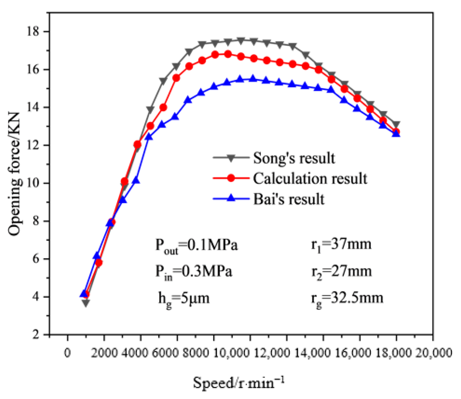
To verify the reliability of the established numerical model, a validation case was constructed using the same geometric parameters and operating conditions as those reported by Song [
20] and Bai [
12]. The outer and inner diameters of the sealing face were 37 mm and 27 mm, respectively; the groove-root radius was 32.5 mm, the groove depth was 5 μm, the number of grooves was 12, and the helix angle was 18°. The liquid film thickness was set to 5 μm, with an inlet pressure of 0.3 MPa and an atmospheric pressure outlet. As shown in
Figure 5, the opening-force results predicted by the present model fall within the range reported by Song [
20] and Bai [
12], demonstrating the reliability of the numerical method.
4. Calculation Results and Analysis
4.1. Liquid Film Pressure and Distribution
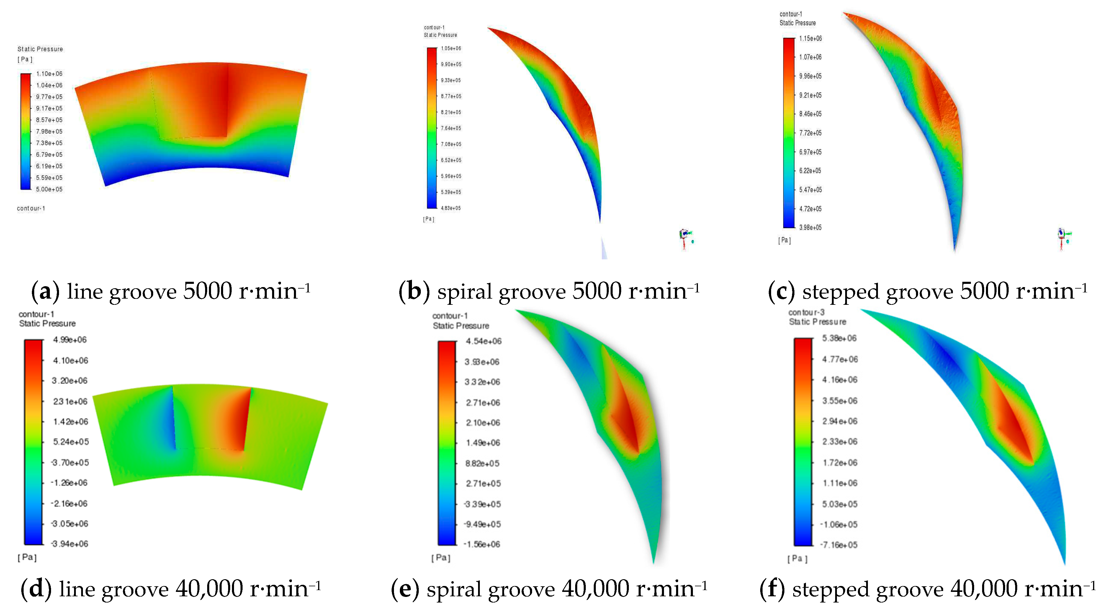
With liquid nitrogen as the working medium, the inlet and outlet pressures were set to 2 MPa and 1 MPa, respectively. To compare the liquid film pressure distributions under different rotational speeds, representative cases at 5000 and 40,000 r·min
−1 were selected. According to the Reynolds number assessment, the laminar model was adopted at 5000 r·min
−1, while a turbulence model was employed for the cases at 10,000 r·min
−1 and above. The corresponding pressure distributions of the three groove configurations are shown in
Figure 6.
As shown in
Figure 6a–c, at 5000 r·min
−1, the pressure fields of the three groove configurations are relatively smooth, and no pronounced negative-pressure region is observed. The maximum pressures of the line, spiral, and stepped grooves are approximately 1.10 MPa, 1.05 MPa, and 1.15 MPa, respectively, while the corresponding minimum pressures are approximately 0.50 MPa, 0.483 MPa, and 0.398 MPa. Among the three groove configurations, the stepped groove exhibits the highest pressure peak and a more evident pressure-concentration region near the groove root, indicating a stronger local hydrodynamic pressure-generation effect. At 40,000 r·min
−1, as shown in
Figure 6d–f, the pressure gradients become more pronounced, and the hydrodynamic pressure-generation effect is significantly enhanced. The maximum pressures of the line, spiral, and stepped grooves are approximately 4.99 MPa, 4.54 MPa, and 5.38 MPa, respectively, while the minimum pressures are approximately −3.94 MPa, −1.56 MPa, and −0.72 MPa, respectively. For the stepped grooves, the high-pressure regions are mainly concentrated near the groove root. They show the highest-pressure peak and a larger high-pressure area, while the low-pressure regions are less pronounced, suggesting better local load-bearing capability. The spiral grooves exhibit pressure convergence along the groove line and show certain flow-guiding and pressure-boosting effects, but their overall pressure enhancement is weaker than that of the stepped grooves. In contrast, the line grooves show a more dispersed pressure distribution and a larger proportion of low-pressure regions, resulting in a weaker hydrodynamic effect. This difference is mainly attributed to the groove geometry. The stepped grooves form a local convergent flow channel through the groove-depth variation, which enhances fluid compression, increases film pressure, and expands the high-pressure region. The spiral grooves promote fluid convergence through the flow-guiding effect, whereas the line grooves lack clear convergence and guidance, making the fluid more prone to radial flow and less favorable for pressure concentration. Therefore, the stepped grooves exhibit the best overall performance in terms of liquid film pressure distribution and load-bearing capacity.
The local low-pressure regions shown in
Figure 6 indicate a substantial pressure reduction induced by the hydrodynamic action of the groove geometry. However, the physical interpretation of these values depends on the pressure reference adopted in the CFD model. Therefore, the occurrence of cavitation should be evaluated on the basis of absolute pressure rather than simply from the sign of the reported pressure value. In particular, the local absolute pressure should be compared with the saturation vapor pressure of liquid nitrogen at the specified temperature.
4.2. Influence of Working Condition Parameters on Sealing Performance
4.2.1. Influence of Rotational Speed
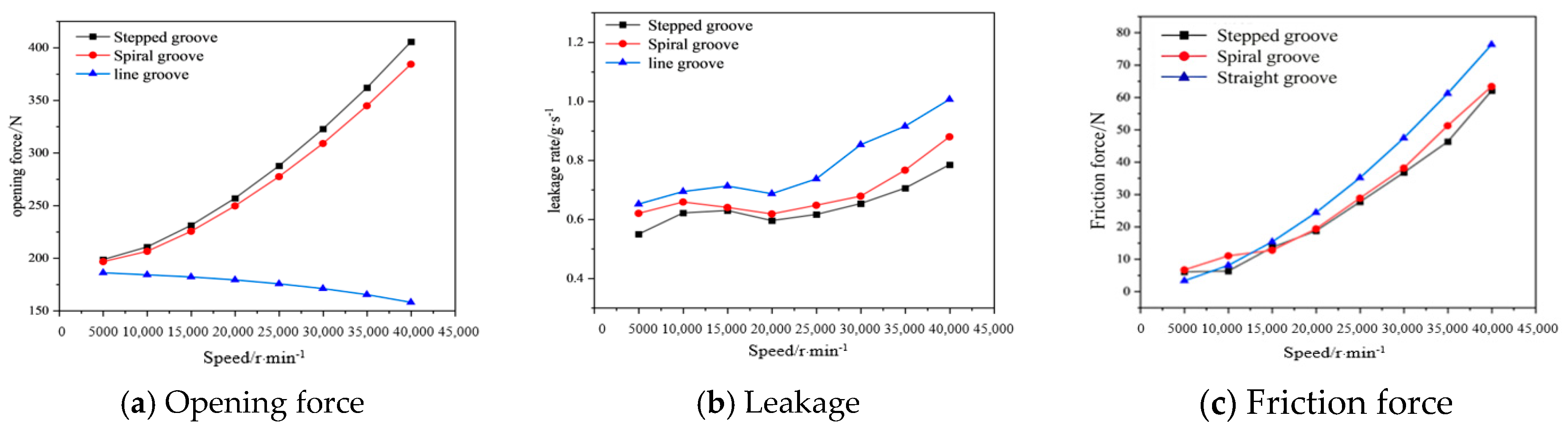
Figure 7 illustrates the variation trends of the opening force, leakage rate, and friction force of the mechanical seals when the rotational speed was set in the range of 5000 to 40,000 r·min
−1, with line grooves, spiral grooves, and stepped grooves investigated at different rotational speeds. The results indicate that within the investigated rotational speed range, the stepped grooves consistently exhibit a higher opening force and a lower leakage rate, with their comprehensive sealing performance superior to that of the spiral grooves and line grooves. With the increase in rotational speed, the leakage rate of the three groove types all exhibit an upward trend, while the opening force of the stepped grooves and spiral grooves increases steadily, and the opening force of the line grooves shows a slight decrease. The friction forces of all three groove configurations increase with increasing rotational speed. This behavior is mainly attributed to the increase in circumferential velocity, which enhances the velocity gradient and viscous shear within the liquid film. Among the three groove configurations, the stepped groove consistently exhibits the lowest friction force throughout the investigated rotational speed range, indicating its superior friction-reduction performance. When the rotational speed increases from 5000 r·min
−1 to 40,000 r·min
−1, the opening force of the stepped grooves is 18.23% and 62.43% higher than that of the spiral grooves and line grooves, respectively, while the leakage rate of the stepped grooves is 6.40% and 17.58% lower than that of the spiral grooves and line grooves, respectively. The underlying mechanism for this is that, with the increase in rotational speed, the flow rate of the sealing medium entering the groove region increases, the viscous shear effect of the liquid film is enhanced, and high-pressure regions are more likely to form near the groove root, thereby driving the overall increase in the opening force. For the stepped grooves, the sudden change in groove depth forms a local convergent flow channel, leading to a more pronounced squeezing and convergence behavior of the fluid in the groove region and a gradually enhanced local secondary flow effect, which delivers a more significant hydrodynamic pressure boosting effect. Therefore, with the increase in rotational speed, the stepped grooves exhibit a more obvious increase in the amplitude of opening force, and simultaneously have a better suppression effect on the growth of leakage rate. By contrast, the line grooves have a weak flow guiding and pressure boosting effect, making it difficult for the pressure to concentrate, thus resulting in a lower opening force and inferior leakage control capability. According to the calculated Reynolds numbers, the laminar model was adopted at 5000 r·min
−1, while a turbulence model was employed at 10,000, 20,000, and 40,000 r·min
−1 to account for the increasing non-laminar effects under high-speed operating conditions.
4.2.2. Influence of Pressure Difference
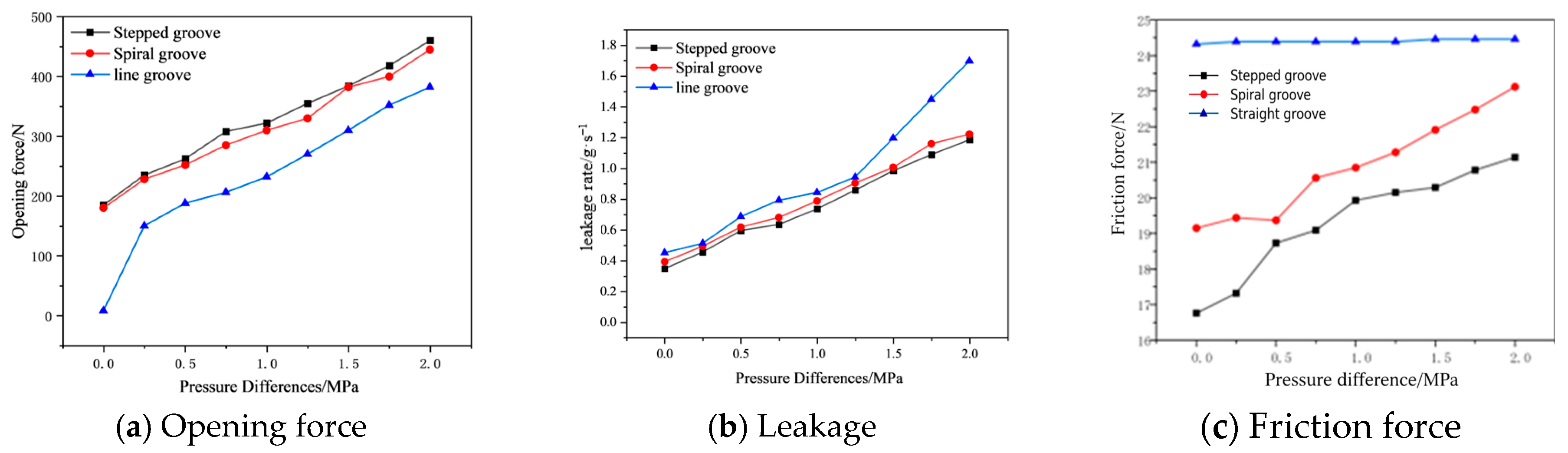
Figure 8 shows the opening force, leakage rate, and friction force of straight, spiral, and stepped grooves under pressure differences from 0 to 2 MPa. For all three groove types, both parameters increase with rising pressure difference. The stepped grooves exhibit the best overall sealing performance: the opening force of the stepped grooves is 12.9% and 33.5% higher than that of the spiral grooves and line grooves, respectively; in terms of the leakage rate, the leakage rate of the stepped grooves is 5.31% and 19.79% lower than that of the spiral grooves and line grooves, respectively. With the increase in pressure difference, the driving force for the sealing medium to flow from the outer radius to the inner radius is enhanced; the load-bearing capacity of the liquid film is improved accordingly; thus, the opening force of the three groove types all exhibit an increasing trend. The enhancement of the pressure difference-driven flow also leads to a synchronous increase in the leakage rate. For the stepped grooves, with the increase in pressure difference, the amount of sealing medium entering the groove region increases; the local throttling and convergent effect formed by the sudden change in groove depth becomes more pronounced, and the squeezing and convergence effect of the fluid in the groove region is enhanced, thereby improving the flow blocking capability of the groove region and making its leakage reduction effect more prominent. The friction force of the stepped groove increases gradually with increasing pressure difference but remains lower than those of the spiral and line grooves throughout the investigated range.
4.2.3. Influence of Liquid Film Thickness
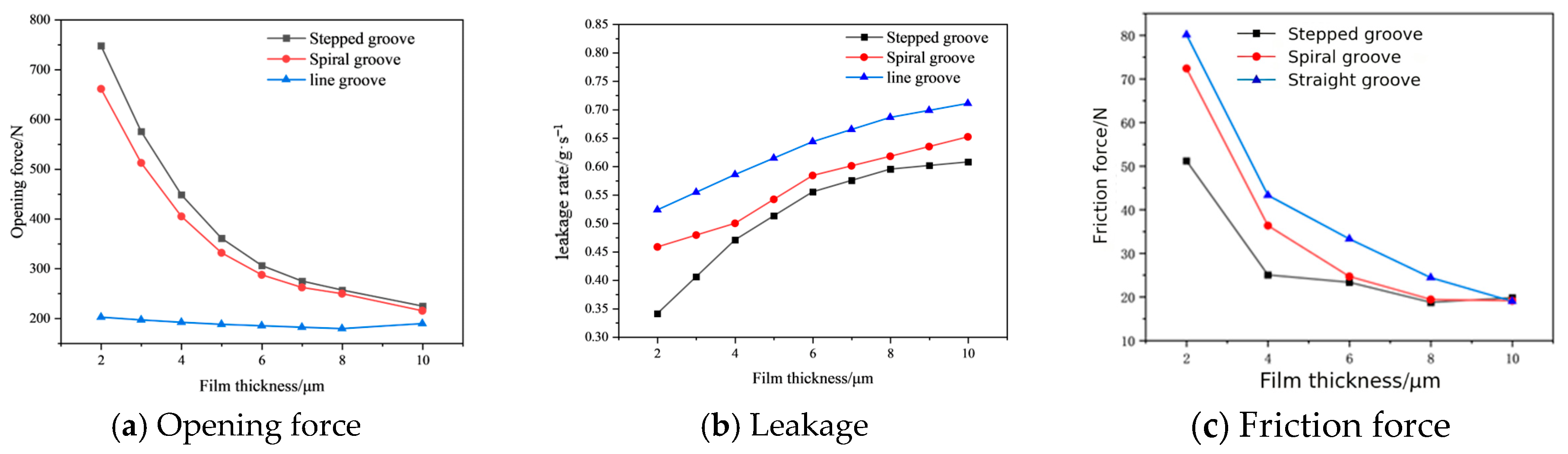
Figure 9 illustrates the variations in opening force, leakage rate, and friction force of mechanical seals with straight, spiral, and stepped grooves as the liquid film thickness increases from 2 to 10 μm. As the liquid film thickness increases, the opening force of all three groove types generally decreases, whereas the leakage rate gradually increases and then tends to level off. Within the investigated range, the stepped grooves consistently show a higher opening force and a lower leakage rate, indicating better overall sealing performance than the spiral and line grooves. For opening force, the advantage of the stepped grooves is more evident at low liquid film thickness, where the opening force is 13.08% higher than that of the spiral grooves. For leakage rate, the stepped grooves reduce leakage by approximately 8.60% and 18.40% compared with the spiral and line grooves, respectively. This is because increasing liquid film thickness weakens the convergent compression effect, reduces the hydrodynamic effect, and attenuates the high-pressure regions near the groove root, thereby decreasing the opening force. Meanwhile, the enlarged flow channel allows fluid to pass more easily through the sealing gap, resulting in increased leakage. For the stepped grooves, the sudden change in groove depth forms a local convergent flow channel, which enhances the load-bearing capacity of the liquid film and improves throttling performance under different film thickness conditions. The friction forces of all three groove configurations decrease with increasing liquid film thickness. The stepped groove exhibits a lower friction force, particularly at relatively small film thicknesses, indicating its advantage in friction reduction.
4.3. Influence of Structural Parameters on Sealing Performance
4.3.1. Influence of Groove Depth
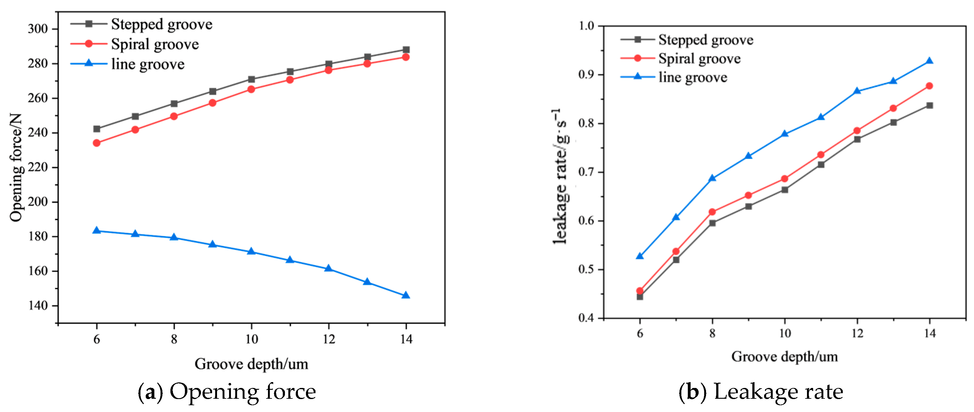
For the stepped groove, the first-step groove depth hg1 is fixed at 4 μm, while the second-step groove depth hg2 is varied from 6 to 14 μm. For convenience, hg2 is denoted by hg in the following parametric analysis.
Figure 10 illustrates the variations in sealing performance parameters of mechanical seals with the three groove types as groove depth changes, where (a) shows the opening force and (b) shows the leakage rate. The groove depth ranges from 6 to 14 μm. The results show that the opening force of all three groove types increases with groove depth. Compared with spiral and line grooves, the stepped grooves consistently exhibit a higher opening force and a lower leakage rate over the entire groove depth range, with relatively stable curves and no obvious intersections. The opening force of the stepped grooves is 2.25% and 59.27% higher than that of the spiral and line grooves, respectively, while the leakage rate is reduced by 3.35% and 10.95%, respectively. This is because increasing groove depth enlarges the groove-region volume, allowing the sealing medium to form a stronger squeezing and convergence effect near the groove root, which enhances the hydrodynamic effect and increases the opening force. Meanwhile, the larger groove depth improves the flow capacity of the groove region, resulting in increased leakage. For the stepped grooves, the sudden transition between shallow and deep grooves forms local convergent and throttling regions, which promotes local pressure build-up, improves the liquid film load-bearing capacity, and more effectively suppresses radial leakage.
4.3.2. Effect of Groove Number
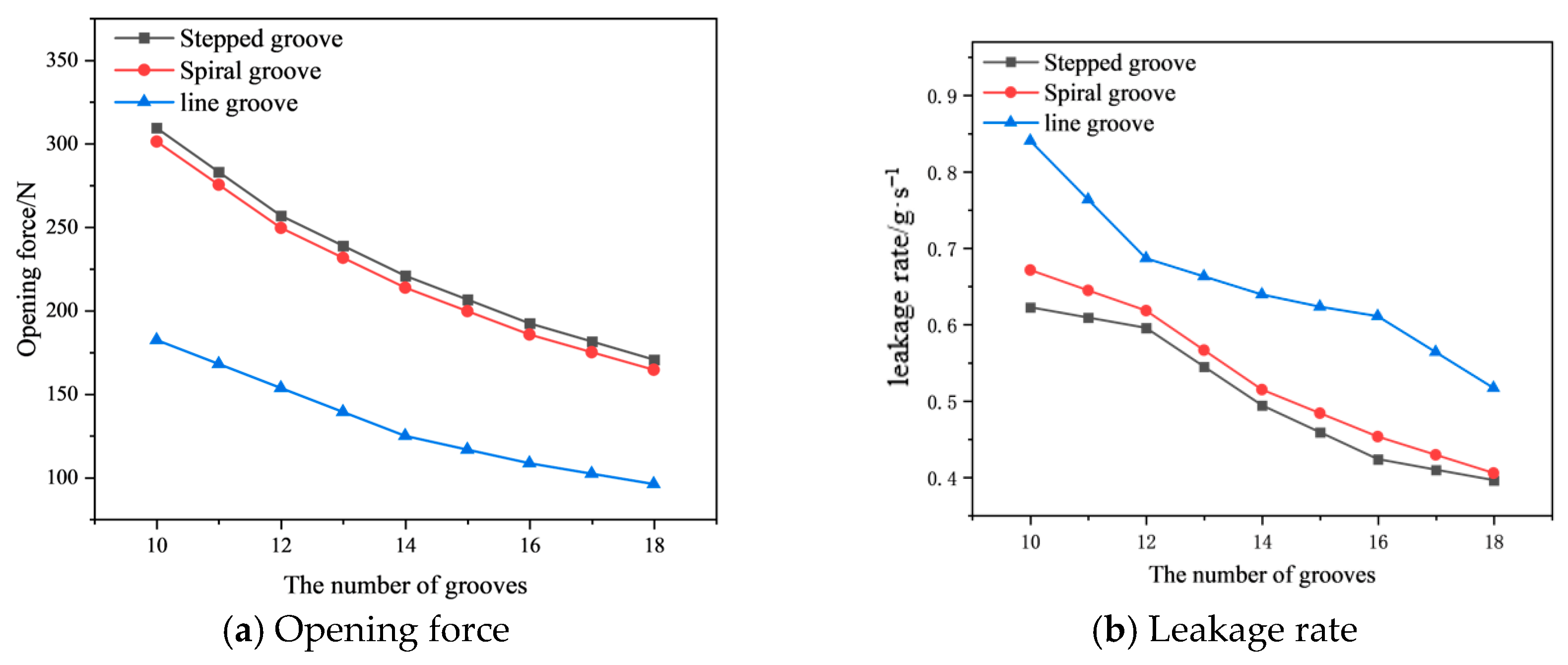
Figure 11 illustrates the variations in opening force and leakage rate for three groove types as a function of groove number. As the groove number increases from 10 to 18, the opening force of all three groove types exhibits an overall declining trend, with the stepped groove consistently maintaining a slightly higher opening force than the spiral groove across all groove numbers, surpassing the other two groove types by 3.26% and 69.50%, respectively. As shown in Fig.11 (b), increasing the groove number generally reduces the leakage rate, with the stepped groove achieving reductions of 4.91% and 25.70% relative to the other two groove types. The decline in opening force with increasing groove number can be attributed to the reduction in groove pitch, which subdivides the pressurization units and restricts the pressure build-up process. Simultaneously, the narrowing of the equivalent flow channels and the associated increase in flow resistance contribute to the reduction in leakage. By virtue of its local pressurization and segmented throttling mechanisms, the stepped groove geometry sustains high load-carrying capacity and effectively suppresses leakage across different groove numbers.
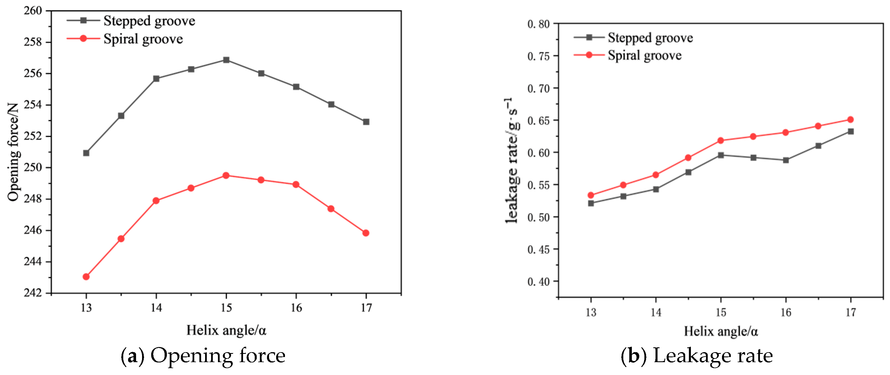
4.3.3. Effect of Helix Angle
Since the groove lines of the radial line groove are distributed along the radial direction without tangential pumping characteristics, the helix angle parameter is geometrically inapplicable to this groove type; accordingly, the line groove is excluded from the comparative analysis in this subsection.
Figure 12 illustrates the effect of varying helix angle on sealing performance. As the helix angle increases from 13° to 15°, the opening force of the stepped groove exceeds that of the spiral groove by 2.95%. This enhancement is attributed to the wedge-shaped clearance formed at the interface between the grooved and un-grooved regions, in conjunction with the step structure, which imparts a pronounced guiding and compressive effect on the fluid. This promotes migration of the sealing medium in the direction of decreasing wedge clearance and induces further compression, thereby intensifying the hydrodynamic effect. However, as the helix angle continues to increase beyond this point, the radial aperture of the groove widens, and the equivalent wedge clearance broadens, which weakens the guiding compression mechanism and consequently diminishes hydrodynamic pressure generation, leading to a decline in load-carrying capacity. The leakage rate exhibits an overall increasing trend with increasing helix angle. Under the same helix angle, the leakage rate of the stepped groove remains consistently lower than that of the spiral groove, reflecting superior flow restriction and leakage suppression capability; across the tested helix angle range, the leakage rate of the stepped groove is 3.95% lower than that of the spiral groove. Therefore, no single helix angle simultaneously maximizes the opening force and minimizes the leakage rate within the investigated range; the preferred angle depends on the performance criterion considered.
4.4. Tribological Characteristics
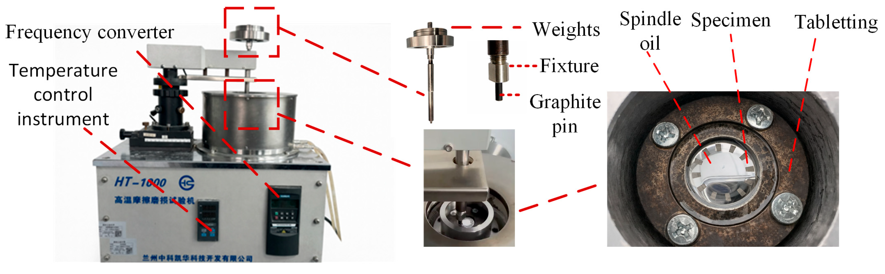
This experiment was designed to investigate the tribological behavior of mechanical seals under low-speed steady-state operating conditions, where hydrodynamic film formation is relatively limited, and the frictional response is more sensitive to the groove configuration. The tribological test rig is built around an HT-1000 high-temperature friction and wear testing machine and consists of three key functional units. The structural diagram of the friction test bench is shown in
Figure 13. The first is the loading and clamping unit, in which the applied load is transmitted to the contact surface through a loading plate; a fixture secures the graphite pin and ensures its alignment with, and stable contact against, the test specimen and groove region. The second is the test chamber and lubrication unit, where the test zone is placed in an oil trough filled with spindle oil to provide an oil-bath lubrication environment, while the test specimen forms a friction pair with the graphite pin to reproduce the end-face friction process under low-speed operating conditions. The third is the variable-frequency drive control unit, which regulates the rotational speed and enables controlled tests under different low-speed steady-state operating conditions. Through the coordinated operation of these units, comparative friction response tests can be conducted under different load, speed, and lubrication conditions, providing a basis for analyzing tribological differences among groove types. It should be noted that these low-speed tribological tests are conducted under simplified laboratory conditions and are intended for qualitative comparison among the three groove configurations rather than for direct comparison with the high-speed CFD results.
Specimen and test parameters related to the tribological test are supplemented as follows. The rotating ring material was 9Cr18 stainless steel, and the stationary pin was graphite. After polishing by a metallographic grinding and polishing machine, the surface roughness Ra of the ring end face was measured by a ZYGO-ZeGage 3D profilometer. The graphite pin had a nominal diameter of 4 mm, while its contact tip was machined to reduce the effective contact area. The equivalent friction radius was 8 mm. FD2 spindle oil was adopted as the lubricating medium in the oil bath environment. Each group of tests lasted for 30 min, and the total rotational cycles were calculated according to the set rotational speed. It should be noted that actual turbopump mechanical seals generally operate under high-speed and high-PV conditions. However, owing to the limitations of the experimental equipment, specimen dimensions, and contact scale, the full-scale operating conditions of the actual mechanical seal could not be directly reproduced in the present laboratory tests. Therefore, the tribological tests were designed according to the PV similarity criterion. A reduced nominal contact area of the graphite pin was adopted to increase the nominal contact pressure, thereby compensating for the lower experimental sliding velocity. The PV value was calculated as PV = pv, where p = F/Ac is the nominal contact pressure based on the effective contact area Ac, and v is the sliding velocity. The rotational speeds were set to 200 and 400 r·min−1, and the normal loads were set to 10 and 20 N. The PV values corresponding to the lower test condition (200 r·min−1, 10 N) and the upper test condition (400 r·min−1, 20 N) were 0.133 and 0.533 MPa·m/s, respectively. These tests were conducted to comparatively evaluate the tribological performance of the three groove configurations under low-speed steady-state laboratory conditions.
For wear measurement, the profilometer was used to scan the surface topography before and after the test. The wear volume was obtained by comparing the difference between the original profile and the worn profile. The wear rate was further calculated by the formula K = V/(F·L). Three parallel repeated tests were carried out for each working condition to reduce accidental errors. The system error of the friction force sensor and 3D profilometer was within the instrument calibration range.
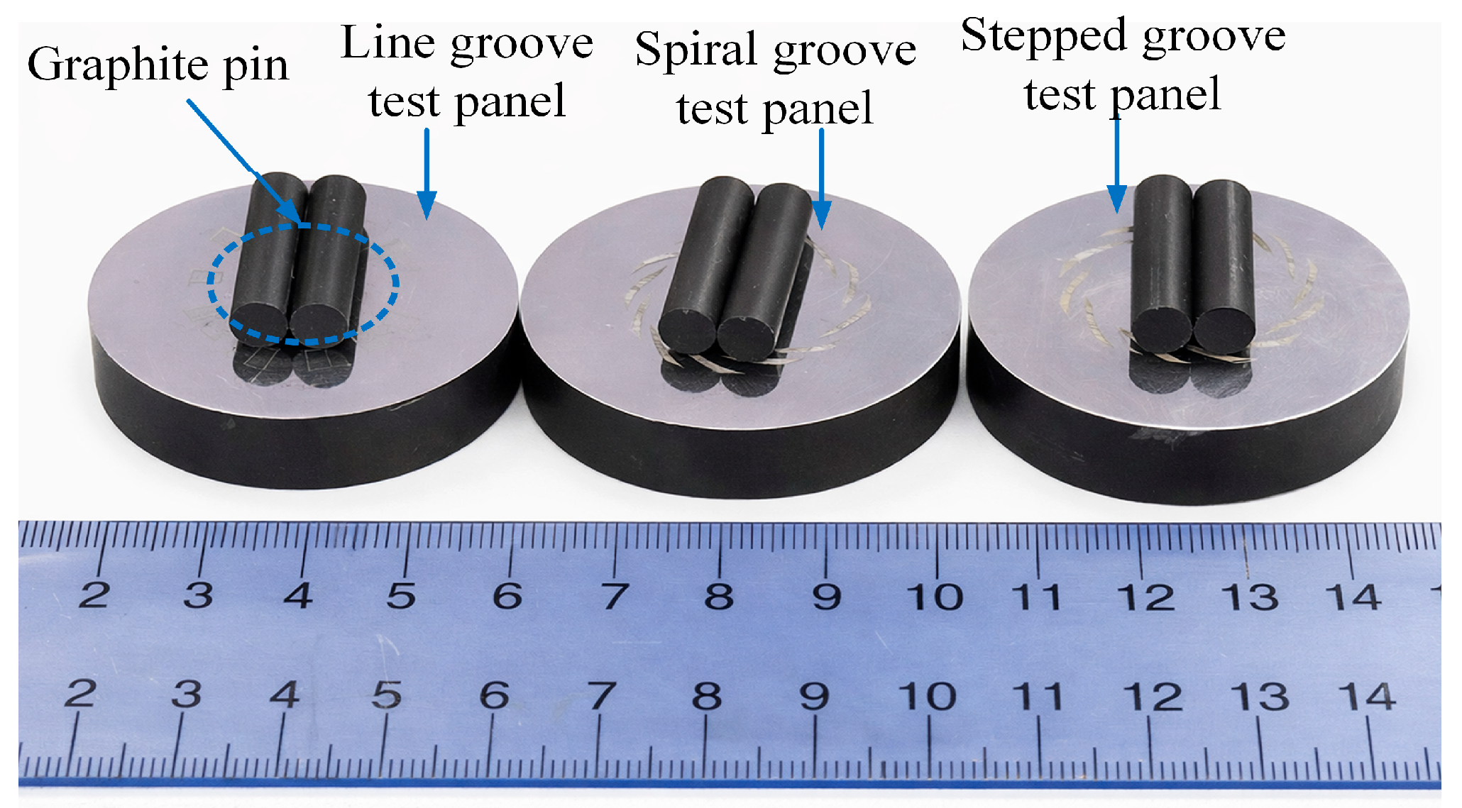
Comparative friction and wear experiments were conducted on the rotating ring end faces with three groove types to characterize the evolution of friction coefficient and wear volume under different operating conditions, and to clarify the effect of groove geometry on end-face tribological performance. The graphite pin–hard ring friction pair was used to take advantage of the self-lubricating and conformable properties of graphite, thereby reducing adhesive wear risk while improving the sensitivity of the test to groove-induced differences in lubricant film formation and friction fluctuation. Before testing, the rotating ring and graphite pin specimens were visually inspected to ensure that no defects, such as chipping or cracking, were present, and their initial surface conditions were recorded, as shown in
Figure 14.
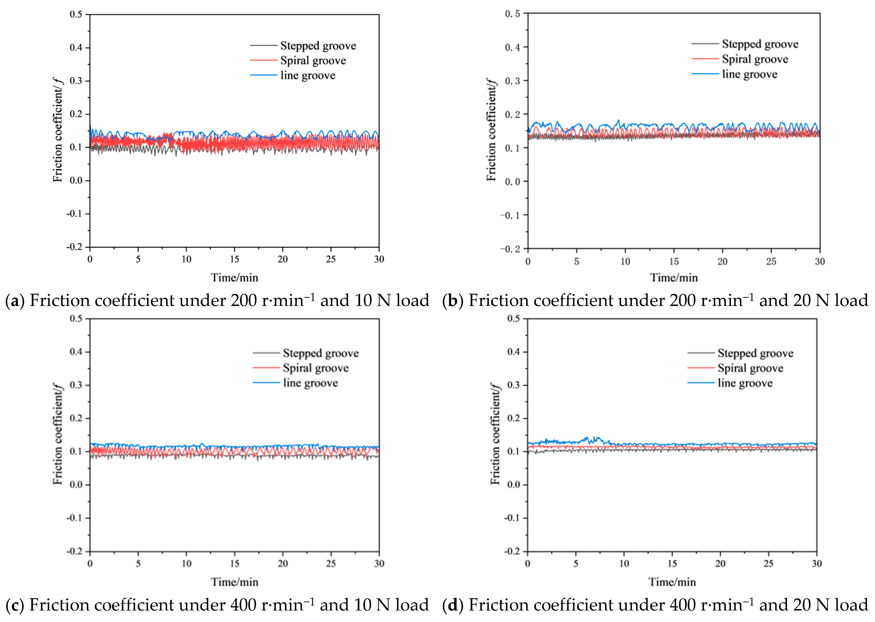
Figure 15 shows the time-dependent variation in the friction coefficient under different speeds and loads.
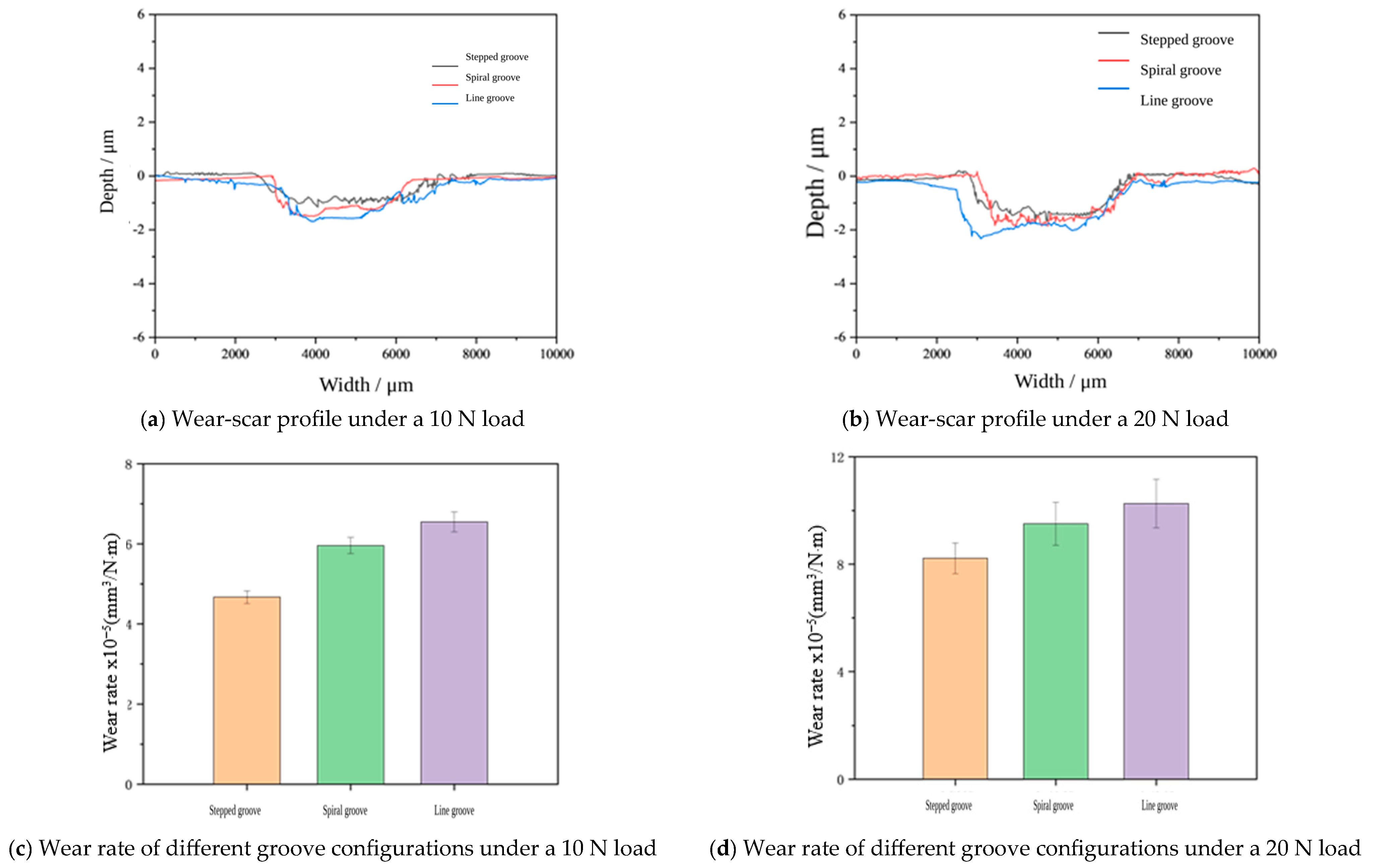
Figure 16 compares the wear behavior of the three groove configurations at 400 r·min
−1. At 10 N, the wear-scar depths of the stepped, spiral, and line grooves are 1.14, 1.45, and 1.68 μm, respectively, with corresponding wear rates of 4.67 × 10
−5, 5.96 × 10
−5, and 6.55 × 10
−5 mm
3/(N·m). At 20 N, the stepped groove also exhibits the lowest wear-scar depth and wear rate. These results indicate that the stepped groove has better wear resistance under the tested conditions.
The friction coefficient is tested at two speeds: 200 r·min
−1 and 400 r·min
−1. Also, two loads are used: 10 N and 20 N. The results are shown for rotational speeds and loads over time in
Figure 15. The friction coefficient changes are tested for three groove types. We look at how the friction coefficient changes at 200 r·min
−1 and 400 r·min
−1. The loads used are 10 N and 20 N to test the friction coefficient.
Figure 15 presents the results for the friction coefficient over time. The friction coefficient changes are shown at different rotational speeds. The loads of 10 N and 20 N are used to test friction coefficient changes. The three groove types are tested at the two speeds. The results in
Figure 15 show friction coefficient changes over time.
As shown in the figure, all groove types exhibit an initial run-in period, after which they gradually reach a relatively stable state. Significant differences can be observed among the three groove types in terms of both the friction coefficient level and its fluctuation amplitude. Among them, the stepped groove performs best, showing lower friction coefficients and smaller fluctuations than the other groove types under all tested rotational speeds and loads. This indicates that it has a stronger liquid film load-carrying capacity and better operational stability. The spiral groove ranks second, while the line groove performs the worst, exhibiting higher friction coefficients and larger fluctuations, which suggests a weaker load-carrying capacity of the lubricant film. A closer examination shows that the stepped groove performs particularly well at 400 r·min−1 and 10 N, where it exhibits the lowest friction coefficient and the most stable variation over time. This indicates that a more favorable lubrication state is established under this condition, resulting in the best load-carrying performance. Compared with the spiral groove and the line groove, the stepped groove maintains a lower and more stable friction coefficient throughout the test. This behavior can be attributed to the fact that higher rotational speed promotes the formation of a stable lubricant film on the grooved end face, while the localized wedge-shaped pressurization zones created by the stepped structure further enhance the hydrodynamic effect, thereby improving the load-carrying capacity of the lubricant film and reducing direct contact between the sealing faces.
5. Conclusions
(1) The stepped groove more readily generates localized high-pressure zones near the groove root and step-transition regions. At 40,000 r·min−1, the maximum liquid film pressure reaches approximately 5.38 MPa, compared with 4.54 MPa for the spiral groove and 4.99 MPa for the line groove, demonstrating the stronger local hydrodynamic pressure-generation capability of the stepped groove.
(2) The stepped groove outperforms both the spiral groove and the line groove in terms of opening force enhancement and leakage reduction. Within a groove depth range of 6~14 μm, the opening force of the stepped groove is 2.25% and 59.27% higher than those of the spiral groove and line groove, respectively, while the leakage rate is 3.35% and 10.95% lower. Within the investigated helix-angle range of 13–17°, the stepped groove maintains better sealing performance than the spiral groove. The maximum opening force of 256.867 N occurs at 15°, whereas the minimum leakage rate of 0.52071 g/s is obtained at 13°.
(3) Under high-speed operating conditions, the stepped groove demonstrates superior performance in load carrying and leakage suppression. As the rotational speed increases from 5000 r/min to 40,000 r/min, the opening force of the stepped groove is much stronger than that of the groove and the line groove. It exceeds them by 18.23% and 62.43%, respectively. At the same time, the leakage rate is 6.40% and 17.58% lower. This confirms that it has the best sealing performance at these speeds.
(4) Under the low-speed steady-state laboratory conditions, the stepped groove exhibits better tribological performance than the spiral and line grooves. At 400 r·min−1 and a normal load of 10 N, the stepped groove shows an average friction coefficient of approximately 0.095, a wear-scar depth of 1.14 μm, and a wear rate of 4.67 × 10⁻⁵ mm3/(N·m), all lower than those of the other two groove configurations. These results demonstrate the favorable friction-reduction and wear-resistance performance of the stepped groove under the tested conditions.
(5) The present study has several limitations. Constant thermophysical properties are adopted for liquid nitrogen, while thermo-mechanical deformation and cavitation/phase-change effects are not considered. In addition, the tribological tests are conducted under simplified low-speed laboratory conditions. Future work will focus on thermo-fluid–solid coupling, two-phase flow, and validation under conditions closer to actual turbopump operation. Future work will also incorporate turbulence and inertial effects into the numerical model to improve prediction accuracy under ultra-high-speed operating conditions.



 ,
,