Article

Dynamic Analysis of Brush-Seal Bristles Using an Incremental Corotational Beam and a Stick–Slip Friction Model


Virtual Engineering Platform Research Division, Korea Institute of Machinery and Materials (KIMM), Daejeon 34103, Republic of Korea
*
Author to whom correspondence should be addressed.
Lubricants 2026, 14(9), 354; https://doi.org/10.3390/lubricants14090354
Submission received: 6 August 2026 / Revised: 1 September 2026 / Accepted: 10 September 2026 / Published: 15 September 2026
(This article belongs to the Special Issue Mechanical Tribology and Surface Technology, 3rd Edition)

Abstract

The dynamic behavior of brush-seal bristles governs seal performance and life. Brush-seal hysteresis and the contact and friction of the bristles have been studied extensively by experiments, by three-dimensional finite-element analysis, and more recently by models of inter-bristle friction. What remains is to combine these consistently within a reduced-order multibody analysis and to fix, on physical grounds, the parameters that such a combination requires. This work implemented, in C++ and Python within the open-source multibody system Exudyn, an incremental corotational beam with an analytic tangent stiffness and analyzed the three-dimensional large-deformation dynamics of a bristle. A stick–slip friction model treats the stick–slip transition continuously, and its two friction parameters—left to user input in commercial codes—are derived from the elastic energy of the contact point. Contact is formulated with a Lagrangian constraint at the contact point, and inter-bristle friction damping is represented by Rayleigh damping based on a measured loss factor. The implemented beam agrees with the built-in Exudyn beam to within 0.02% (tip displacement) and 0.03% (shape) and is cross-validated against a prior study at a friction coefficient of 0.3. Fixing the contact point reduces the numerical oscillation of the reaction force by about 9 times relative to re-searching it at every step, and the inter-bristle friction damping yields a dynamic response distinct from material damping alone. The friction force recorded during the analysis is a single-valued function of the elastic state of the contact, reaching the limiting friction exactly when the elastic slip reaches the derived limit, and it reverses sign between incursion and retraction.

1. Introduction

A brush seal is a non-contacting sealing component used for leakage control in rotating machinery such as gas turbines and steam turbines, in which a bundle of fine metal bristles conforms to the rotating-shaft surface and blocks the leakage path. Because it reduces the leakage rate substantially compared with a labyrinth seal and thereby improves machine efficiency, it has become a key element in the design of high-efficiency turbomachinery. The flow and the pressure distribution inside the seal were established in early work that combined experiment and theory [1].
During operation, when the rotating shaft is displaced radially the bristles bend through large angles and recover, and in this process the friction, large deformation, and dynamic response between the bristles and the shaft and between the bristles and the backing ring (also called the backing plate in the literature) govern the reaction force, leakage, and wear of the seal and hence its reliability and life. The three-dimensional dynamic behavior of the bristles therefore needs to be analyzed accurately, yet existing approaches have not addressed it sufficiently.
The hysteresis of brush seals and the stiffening of the bristle pack with pressure have been established experimentally for a long time. After the rotor has moved into the bristle pack, the displaced bristles do not recover immediately against the frictional forces between themselves and the backing ring so that a leakage increase of more than a factor of two is observed following rotor movement, and this leakage hysteresis persists until the pressure load is removed [2,3]. Under pressure the bristle pack can also exhibit a considerable stiffening effect, which results from inter-bristle friction loads making it more difficult for the bristles to flex during shaft excursions [2,3]. In addition, the leakage flow presses the bristles radially inward, and this blow-down raises the contact load, particularly on the upstream bristles, and thereby affects the life of the seal [2,3,4]. The benefit of brush seals, a leakage reduction of up to about 50% relative to labyrinth seals [2,3], must therefore be assessed together with this contact and friction behavior.
Such behavior is difficult to describe with simple beam theory alone. Crudgington and Bowsher [5] compared the hysteresis loop measured in stiffness tests of a bristle pack against a sequence of models ranging from simple beam elements to multi-layer nonlinear three-dimensional contact models. They showed that simple beam models agree well with beam theory but not sufficiently with the test data, and that only the nonlinear models including bristle-to-bristle and bristle-to-backing-plate contact reproduce the measured hysteresis. They attributed the increased pack stiffness mainly to the interaction between bristles.
Structural analyses subsequently developed into three-dimensional finite-element models that include rotor–bristle, bristle–backing-plate, and inter-bristle contacts with friction. Duran et al. [6] built a test rig capable of stiffness testing under pressure and rotor rotation and performed the corresponding three-dimensional finite-element analyses; they carried out transient analyses including inertial effects for the rotating condition and correlated the computed bristle tip forces with dynamic test data, reporting good agreement. The inter-bristle, backing-plate, and rotor–bristle friction coefficients are, however, supplied as inputs to those analyses. The tip force exerted on the rotor has also been measured directly in rig tests [7], and the contact mechanics of rotor–bristle interference was established by treating the bristle as a cantilever and analyzing the contact force that follows from the interference [8]. Duran [9] separately proposed a closed-form bristle tip force formulation including rotor–bristle, inter-bristle, and bristle–backing-plate interactions and obtained a high level of correlation with tip forces measured under pressurized and unpressurized conditions.
The dynamic characteristics of brush seals have also been examined. Duran [10] combined nonlinear contact simulations with frequency-domain analyses to evaluate the critical modes of the bristle pack and the seating load and correlated transient predictions with dynamic tip-force measurements. That study notes that bristles which are not properly seated operate standalone, without interaction and the accompanying frictional damping, and may then flutter and lead to seal failure; this is consistent with the premise of the present work that friction within the bristle pack acts as a source of damping (Section 2.4).
In a prior study, Phan et al. [11] characterized the frictional hysteresis and hang-up of a brush seal using analytical simple-beam theory, numerical fluid–structure interaction (coupling of aerodynamic loads and beam bending), and Coulomb friction. This approach effectively characterized brush-seal hysteresis within a quasi-static, planar framework; multibody dynamics including inertia, a stick–slip friction model, three-dimensional geometrically nonlinear large deformation, and the Lagrangian constraint at the contact point lie outside its scope. Commercial multibody dynamics codes such as RecurDyn [12] and MSC Adams [13] do provide a stick–slip friction model, but their parameters are left to user input. The present work builds on the following prior achievements. The measured structural loss factor of the bristle pack reported by Delgado and San Andrés [14] ( γ 0.19 , ζ 9.5 % ) and the material damping of a single bristle reported by Vanegas-Useche et al. [15] provide the basis for setting the Rayleigh damping from inter-bristle friction (Section 2.4). In addition, the stick–slip transition and the friction relaxation that appears when sliding stops (the kinetic–static transition) are already established phenomena in friction physics (e.g., rate-and-state friction [16,17]); the present stick–slip friction model represents them, and their time-dependent behavior is elucidated through dynamic analysis (Section 5).
The same group subsequently extended the model to include inter-bristle frictional contact, shaft and backing-ring interaction, and three-dimensional bristle bending coupled in two planes [18]. That model represents the bristle as a three-dimensional static Euler–Bernoulli beam and is based on linear beam theory; it showed that inter-bristle frictional contact substantially modifies the distribution of local tip force within the pack and can thereby influence local wear and heat generation.
Experimental work likewise links the mechanical contact history to leakage, heat generation, and service life. Li et al. [19] carried out cyclic tests on a low-hysteresis brush seal in which the rotor speed was increased and decreased, measuring the leakage, the hysteresis, and the temperature rise at the bristle tips caused by frictional heat. They reported that a smaller hysteresis gives a lower temperature rise and is therefore favorable for service life, although a low-hysteresis structure may increase leakage. More recently, a two-dimensional porous-medium leakage-flow model has been combined with a three-dimensional bristle mechanics model to address the multiphysics behavior of brush seals [20].
Despite these advances, several methodological issues remain from the standpoint of a reduced-order multibody analysis. First, a geometrically nonlinear formulation is required that can carry large bristle rotations through time integration. Second, the transition between sticking and sliding in frictional contact must be handled without introducing excessive numerical discontinuity. Third, the parameters governing that transition should be related to physical contact properties rather than chosen as arbitrary numerical inputs. Fourth, the normal contact reaction is better determined consistently with the system equations than through an arbitrary penetration stiffness. Fifth, when the surrounding bristles are not solved explicitly, the dissipation measured for an actual pack must be represented in an appropriate reduced-order form. Finally, the numerical treatment of the contact point itself affects the stability of the computed reaction force.
This work implemented, in C++ and Python within the open-source multibody dynamics system Exudyn [21], an incremental corotational beam with an analytic tangent stiffness based on a standard corotational formulation and analyzed the three-dimensional geometrically nonlinear large-deformation dynamics of a bristle. A stick–slip friction model was applied to the contact, and its parameters d m a x and d v were derived from the elastic energy of the contact point. The bristle contact is represented by a Lagrangian constraint at the contact point, and the inter-bristle friction is represented by grounded Rayleigh damping. The implemented beam was verified against the built-in Exudyn solver and cross-validated against the prior study [11] at a friction coefficient of 0.3.
The corotational formulation used in this study is an established framework for geometrically nonlinear structural analysis [22] and is not proposed here as a new beam theory. Three-dimensional large deformation and dynamic analysis have likewise already been addressed in brush-seal research. The formulation is adopted for practical and methodological reasons: it permits three-dimensional large rotation while allowing an analytic tangent stiffness and an element-level damping term to be incorporated into a user-defined multibody element.
The contribution of this paper lies not in the individual novelty of the corotational beam, of three-dimensional deformation, or of frictional contact, but in integrating them consistently within a reduced-order open-source multibody framework and in fixing the quantities that this framework requires from physical or measurable properties wherever possible. Specifically, the study: first, implements an incremental corotational beam with an analytic tangent stiffness and an element-level damping capability, resolving the limitation that the built-in beam cannot account for damping; second, determines the friction parameters dmax and dv, which commercial codes leave to user input, from the elastic behavior of the contact point; third, imposes the normal contact through a Lagrangian constraint so that no arbitrary penetration stiffness is introduced; fourth, examines how the numerical treatment of the contact point affects the reaction-force oscillation and removes the oscillation associated with contact-point re-search; and fifth, resolves the time-dependent evolution of the friction state through the pressurization, incursion, hold, and retraction phases.
The paper is organized as follows. Section 2 describes the theoretical background of the incremental corotational beam, the stick–slip friction model, the formulation of the contact, and the bristle-pack damping. Section 3 explains the single-bristle analysis model and its implementation. Section 4 presents the analysis results for solver verification, the friction parameters, the contact-point treatment, the comparison with the prior study [11], and the rotation effect; Section 5 discusses their meaning and limitations; and Section 6 summarizes the conclusions and future work.

2. Theoretical Background

2.1. Incremental Corotational Beam

The three-dimensional model of this work is described as a constrained multibody system. For the nodal coordinates q,
M q ¨ + C q ˙ + f int ( q ) + Φ q T λ = f ext ( q , q ˙ , t ) , Φ ( q ) = 0
Each node carries three translations and four Euler parameters, that is, seven coordinates subject to one normalization constraint, so that it has six degrees of freedom. The internal force f int is supplied by the incremental corotational element of this section, and the damping is set as C = β K in Section 2.4. The external force f ext consists of the distributed follower load due to the pressure difference and the friction forces of Section 2.2. The constraints Φ comprise the nodal normalization, the clamp at the root, and the contact of Section 2.3; the Lagrange multiplier λ of the contact constraint is the quantity reported in this paper as the reaction force. The equations are integrated in time with a second-order implicit scheme in the index-2 form, which satisfies the constraints at the velocity level, and a Newton iteration on the residual is performed at every time step. Because the user element supplies the analytic tangent stiffness (the Jacobian) together with the residual, the iteration does not rely on numerical differentiation (Section 3.2).
Because a brush-seal bristle bends through large angles in response to the radial displacement of the rotating shaft during operation, its dynamic analysis requires a beam formulation that accurately treats the large deformation arising from geometric nonlinearity. In this work each bristle is discretized into multi-node beam elements, and an incremental (updated-Lagrangian) corotational formulation is applied to each element.
The corotational formulation separates the element motion into a rigid-body rotation and a pure deformation. For each element a corotational frame Q c = [ e x e y e z ] is defined (axial direction e x , e y orthogonal to the mean of the nodal rotations, and e z = e x × e y ), and the deformation measure q def is measured in this frame. The deformational translation is defined as Q c T ( p node p ref ) [ 0 , 0 , 0 ] T and the deformational rotation as rotvec ( Q c T R node ) ; in this way q def = 0 holds for any rigid-body motion. The local stiffness is given by the 12 × 12 stiffness matrix of a Timoshenko beam,
K local = B T K 6 B , K 6 = diag ( E A , G A y , G A z , G J , E I y , E I z )
and produces no force for rigid-body motion ( K local q rigid = 0 ).
In the incremental form, the material stiffness multiplies not the absolute displacement q but the deformation increment d q def = q def ( q ) q def , 0 so that the internal force is accumulated relative to the previous converged state,
f int = blockdiag ( Q c , 0 ) f 0 , local + K local d q def + β K 0 q ˙ ,
where the subscript 0 denotes a value frozen at the previous converged instant, and the last term is the Rayleigh damping that accounts for inter-bristle friction (Section 2.4). This formulation provides an analytic tangent stiffness without numerical differentiation,
J = f ODE 2 K 0 + f ODE 2 , t ( β K 0 )
and at every converged instant it updates the internal force by f 0 , local + = K local q def q def , 0 and re-freezes Q c , 0 and K 0 in the new reference.
This formulation has the same mathematical basis as the standard corotational formulation adopted by commercial codes such as RecurDyn and Abaqus [23]. In a verification against the built-in Exudyn geometrically exact beam for a clean steel cantilever, the natural frequency agreed to within 0.19% (33.3 Hz), and a trajectory reaching a tip displacement of 121% of the free length and a large rotation of about 80° agreed to within a root-mean-square difference of 5%. This confirms that the accuracy is equivalent to that of the built-in beam even in the large-rotation regime (solver verification in Section 4.1).
The decisive reason for adopting the incremental corotational beam as the standard for bristle analysis is not computational speed but the ability to account for structural damping. The built-in Exudyn geometrically exact beam does not incorporate a damping matrix, so it cannot carry the inter-bristle friction damping grounded in the measured loss factor. In contrast, the incremental corotational beam can impose Rayleigh damping of the form β K at the element level (Section 2.4) and thereby suppresses the high-frequency bending modes during the contact transient. The implementation was carried out in C++ (C++17, compiled with Apple Clang 17.0.0) and Python (version 3.11) within the open-source Exudyn environment (version 1.10.0), as detailed in Section 3.2.

2.2. Stick–Slip Friction Model and Stiction–Sliding Parameters

2.2.1. Stick–Slip Friction Model

In the tangential direction of the bristle–shaft and bristle–backing-ring contacts, a stick–slip friction model that treats the stick–slip transition continuously is applied. This belongs to the same family as the formulation adopted by commercial multibody dynamics codes such as RecurDyn and MSC Adams, which place an elastic element in series at the contact surface and define the pre-slip state in terms of force, that is, deformation (the Jenkins–Iwan model) [24].
For a normal unit vector n ^ and the tangential projector P = I n ^ n ^ T , the tangential slip is v t = P v rel , and the tangential displacement is u t = v t d t . Viewing Coulomb friction through the maximum-dissipation principle, the tangential force divides into two regimes.
  • Slip ( v t 0 ): f t = μ d N v ^ t , with the magnitude and direction determined.
  • Stick ( v t = 0 ): only the bound |   f t | μ s N is prescribed.
To handle this smoothly, the tangential displacement is decomposed into an elastic part Δ and a slip part u sl ( u t = Δ + u sl ), and the state Equation f t = k t Δ is obtained from the elastic strain energy ψ ( Δ ) = 1 2 k t | Δ | 2 . Because the state is judged by deformation (i.e., force) rather than velocity, the v 0 singularity ( 1 / d v divergence) that appears in a velocity-dependent model μ ( v ) is absent, and the state is updated in a single step without iteration.

2.2.2. STEP5 Smooth Step Function and Friction Coefficient

Every state transition of the stick–slip friction model is expressed by a single fifth-order smooth step function, STEP5. This function connects two values h 0 , h 1 over the interval [ x 0 , x 1 ] with C 2 continuity,
STEP 5 ( x ; x 0 , h 0 , x 1 , h 1 ) = h 0 , x x 0 , h 0 + ( h 1 h 0 ) S ( s ) , x 0 < x < x 1 , s = x x 0 x 1 x 0 , h 1 , x x 1 , S ( s ) = 10 s 3 15 s 4 + 6 s 5 .
S ( s ) is a Hermite polynomial whose value and first and second derivatives are all zero at both ends, so the transition is smooth. Its derivative S ( s ) = 30 s 2 60 s 3 + 30 s 4 attains its maximum value S ( 1 2 ) = 15 8 at the center s = 1 2 , and this value appears directly in the derivation of d m a x below.
For the tangential relative velocity v t and the pre-slip elastic-deformation state Δ ( Δ = clip v t d t , [ d m a x , d m a x ] ), the friction coefficient is assembled from three STEP5 components.
χ ( v t ) = STEP 5 ( v t ; d v , 1 , d v , + 1 ) ( smooth velocity sign indicator , [ 1 , + 1 ] ) ,
μ s ( Δ ) = STEP 5 ( Δ ; d m a x , μ s , d m a x , + μ s ) ( elastic friction in the stick region , | Δ | d m a x ) ,
μ v ( v t ) = sgn ( v t ) STEP 5 | v t | ; d v , μ s , 1.5 d v , μ d ( static kinetic friction transition ) .
Combining these, the friction coefficient is given in two regimes, low speed and high speed,
μ ( v t , Δ ) = 1 χ ( v t ) μ s ( Δ ) + STEP 5 ( v t ; d v , μ s , d v , μ s ) , | v t | d v ( stick and microslip ) , μ v ( v t ) , | v t | > d v ( slip ) .
The tangential friction force opposes the motion, f t = μ ( v t , Δ ) N v ^ t . Because the state Δ is judged by deformation (i.e., force) rather than velocity, the v t 0 singularity of velocity-dependent models is absent, and the state is updated in a single step without iteration. Hence the only free inputs of this model are the two parameters—the stick width d m a x and the transition velocity d v —which are derived from the geometry and material of the contact point in the next subsection.

2.2.3. Derivation of the Stiction–Sliding Parameters

In commercial codes, the two parameters of this model—the maximum pre-slip deformation d m a x and the characteristic transition velocity d v —are usually left to user input. This work derives them from the elastic energy of the contact point and thereby determines them from geometry and material. The quantity d m a x corresponds to the pre-sliding (breakaway) displacement of classical friction studies, in which a contact in static friction behaves as a tangential spring whose displacement is approximately proportional to the applied tangential force up to breakaway; in machine friction models this displacement is normally supplied as a measured or user-selected input [25].
Setting the bound of the stick region, | Δ | μ s N / k , as the maximum pre-slip deformation gives
d m a x = μ s N k t k t = μ s N d m a x
so that k t and d m a x are tied to each other through the two limiting values ( μ s N , d m a x ) . The relation may be read in either direction. If d m a x is regarded as a property of the contact, then k t = μ s N / d m a x gives k t N , in agreement with the classical observation that the tangential contact stiffness scales with the normal load when the coefficient of static friction is approximately constant [25]. Dynamic friction models that carry this pre-sliding displacement as a state variable have been developed, from the Dahl model [26] to the LuGre model [27], and the family is reviewed by Berger [28]. The classical partial-slip solution for spherical contact has the same structure [29,30]. The present work takes the opposite direction: k t is obtained from the tangential stiffness of the bristle, and d m a x follows from it. Incorporating the maximum slope 15 8 of the STEP5 function of Section 2.2.2 gives
d m a x = 15 8 μ s N k t ,
and the characteristic velocity, as a measure of the crossover from elastic energy to motion, is
d v = d m a x · ω n = d m a x k t / m .
The parameter d v is independent of the stick–slip decision (the comparison of the trial force |   f tr | with μ N ); its role is confined to the width of the μ s μ d Stribeck transition. Consequently, when μ s = μ d (the same verification condition as in the prior study [11]), d v vanishes. In the area-contact limit the same quantity is also defined by contact mechanics, the corresponding expression being the Cattaneo–Mindlin [29] relation δ * = 3 μ N ( 2 ν ) / ( 16 G * a ) . The value used in this work is not obtained from that relation but from the tangential stiffness of the bristle determined below; a quantitative comparison of the two routes would require a definition of the contact radius and is outside the scope of this paper.
For the reference geometry (45° lay angle), the two-segment elastic stiffness that accounts for the mutual support of the backing and the tip is k t = 742 N / m , and from its ratio to the contact normal force over the operating range, N / k t 1.08 × 10 5 m , d m a x = 6.07 μ m is obtained, with d v = d m a x k t / m = 0.154 . The backing and the tip have nearly the same k t (742 vs. 728 N / m ) but different contact normal forces, so the two parameters are computed per contact (backing 6.07 μ m , 0.154 ; tip 1.32 μ m , 0.033 ). The stick–slip friction model with these derived parameters suppressed the numerical oscillation of the contact normal force. In particular, with k t fixed as above, the variation in the contact normal force over the operating range is small so that the ratio N / k t stays within ±4.5%, and d m a x = 15 8 μ s ( N / k t ) behaves like a constant. The remaining source of oscillation—the discontinuity of the contact point—is resolved in Section 2.3.

2.3. Contact Formulation

In the contact between the bristle and the backing ring, the direction of the friction force is set by the contact point, the contact point is found from the shape of the bristle, and that shape is in turn produced by the friction force. If the contact point is re-selected at every time step by a nearest-point search, these three quantities form a loop; because the friction force is not solved together within the Newton iteration but is computed from the shape of the previous step and applied as an external load, the loop closes with a one-step lag. As a result the friction direction alternates between two values at every step, and the reaction force oscillates. The oscillating quantity is not the position of the contact point but the direction of the friction force; the instants at which the contact point jumps between nodes only amplify the oscillation and are not its origin.
The present work fixes the contact point at a single point on the bristle. Because the contact point is not searched again, the friction direction does not depend on the previous shape, and the direction and the shape no longer update each other with a one-step lag. As shown below, this choice does not alter the normal contact.

2.3.1. Lagrangian Contact Reaction

If a single-component constraint in the normal direction is imposed between the bristle node and the contact point, then the contact normal force is obtained not from a penalty stiffness but from the Lagrange multiplier λ of the constraint,
N = λ , λ > 0 : compression ( contact ) , λ 0 : tension ( separation ) .
Because the Lagrange reaction is determined from force balance, no arbitrary contact-stiffness constant is introduced. The sign convention of the reaction force is fixed not by physics but by the definition order of the markers, so it was fixed by measurement: in the pressurization phase λ back = + 7.84 mN > 0 was observed, fixing λ > 0 as compression. The friction force is F = μ N , and it becomes zero automatically when λ 0 (using | λ | would mistake tension for compression, so it is excluded by the sign convention).

2.3.2. The Contact Point

The constraint that produces the normal contact acts along a single axial component. This follows the definition of Phan et al. [11], in which the force pressing the bristle against the backing ring is the axial load arising from the pressure difference between the upstream and downstream sides.
This single-component constraint explains the insensitivity to the position of the contact point. The bristle deforms in the circumferential–radial plane and has almost no axial deformation. Measured on the converged shape, the axial component of the bristle axis is below 1%. Hence, even when the contact point moves along the bristle, the axial relative position of the two markers is unchanged, and the same Lagrange multiplier—and therefore the same normal force—results. Changing the constraint direction so that it follows the bristle gives the same result, confirming that the axial constraint is appropriate for this geometry; the significance of this choice is examined further in future work.
What the contact point determines is only the point of application and the direction of the friction force. When the two models are compared with friction removed, the two solutions are identical to the bit even though the contact point, computed afterwards from the shape, does move across five elements. That is, the motion of the contact point enters the solution only through friction.
With friction included, relaxing the friction direction during the Newton iteration suppresses the oscillation: the tip reaction forces of the two models then overlap along both the incursion and the retraction branch, the peak differs by 0.4%, and the position at which contact is released at the end of retraction differs by 4%. This residual is the same to within 0.02% when the relaxation coefficient is changed by a factor of four, so it is not an artifact of the numerical coefficient but a value that is still converging; its full convergence is left to future work. The travel of the contact point itself is unchanged, so what is suppressed is the oscillation, not the physics.
That this formulation removes the numerical oscillation of the contact reaction force is shown quantitatively in Section 4.3.

2.4. Rayleigh Damping from Inter-Bristle Friction

Because the high-frequency bending modes of the bristle severely contaminate the reaction force without damping during the contact transient, structural damping is imposed at the element level. Using stiffness-proportional Rayleigh damping C = β K , the damping ratio of each mode is determined frequency-selectively as
ζ n = β ω n 2 .
The first bending frequency of the bristle (diameter 0.142 mm, free length 23.35 mm, steel) is f 1 = 187 Hz ( ω 1 = 1174.96 rad / s ).
The damping coefficient β is calibrated from the magnitude of the energy dissipation measured for a brush-seal bristle pack. The damping of the bristle divides into two levels. The pure material damping of a single bristle is small, within the structural-damping range of steel ( ζ 0.6 2 % , Vanegas-Useche [15]). The damping measured in a bristle pack, however, is much larger, and its governing mechanism is the dry friction between bristles and between the bristles and the backing ring. The structural loss factor of the bristle pack is measured as γ 0.19 ( ζ 9.5 % , Delgado & San Andrés [14]), a magnitude that the aerodynamic damping of open flow alone cannot explain. That is, a brush seal behaves not as a viscous damper but as a Coulomb damper. That measurement was obtained for a shoed brush seal (20 pads, 153 mm in diameter) excited without shaft rotation and at room temperature [14], so its configuration and operating conditions are not those of the present case; what is taken from it is the magnitude of the pack-level dissipation rather than a local friction law for an individual bristle. The present model transfers that magnitude at the first bending mode through an energy equivalence: the hysteretic damping is replaced by an equivalent viscous damping with ζ 1 = γ / 2 so that the energy dissipated per cycle of harmonic motion is the same.
Accordingly, so that the first bending mode matches the measured loss factor, β is set to
β = 2 ζ 1 ω 1 = γ ω 1 = 0.19 1174.96 = 1.617 × 10 4 .
This value lies between β 1 3.4 × 10 5 , corresponding to the material damping of a single bristle, and the purely numerical stabilization value β = 4 × 10 4 ( ζ = 23.5 % ) without physical basis, and it has the measured basis of inter-bristle friction. With material damping alone a high-frequency oscillation remains in the contact reaction force, whereas the damping grounded in inter-bristle friction completes the analysis stably; this is discussed quantitatively in Section 5.
This equivalence is most appropriate near the frequency range used for the calibration and for responses dominated by that mode. Because stiffness-proportional Rayleigh damping gives a damping ratio proportional to frequency ( ζ n = β ω n / 2 ), a value matched at the first mode damps the higher modes more strongly. This acts favorably here, in suppressing the high-frequency contamination of the contact transient, but it is distinct from the frequency-independent, hysteretic character of the actual pack dissipation. The term is furthermore not a constitutive model of the local Coulomb friction between individual bristles, and it does not represent amplitude-dependent dissipation, reversal of the friction direction, redistribution of contact force among neighboring bristles, or the spatial distribution of frictional heat.

3. Single-Bristle Analysis Model and Implementation

3.1. Single-Bristle Analysis Model

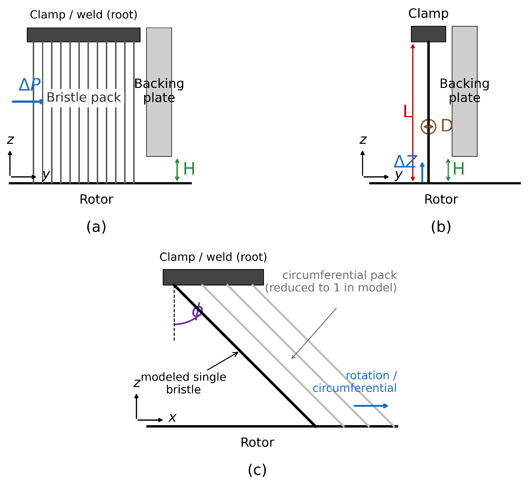
A brush seal is formed by hundreds to thousands of thin metal bristles arranged at a lay angle into a pack, fixed between the backing ring and the retaining ring, with the bristle tips in dynamic contact with the rotating rotor (Figure 1a). Because the total reaction force of the seal is the cantilever response of a single bristle summed over the number of bristles, the dynamic behavior of the bristles is fundamentally determined by the large deformation, friction, and contact of a single bristle. This work therefore models a representative single bristle in three dimensions and analyzes its dynamics (Figure 1b). The bristle is straight in the z–y plane and inclined at the lay angle φ only in the z–x plane, where the circumferential pack is reduced to one representative bristle (Figure 1c). The lay angle couples the radial and the circumferential motion geometrically. If the bristle, clamped at its root, is regarded as an inextensible link, its tip moves along a circular arc about the root so that the instantaneous direction of tip motion is perpendicular to the bristle axis; at ϕ = 45 ° this direction makes 45° with the radial direction and the radial and circumferential displacements are coupled one to one. The coupling can be represented only in a three-dimensional formulation in which each node carries six degrees of freedom (Section 2.1); it is absent from a planar model that has no circumferential degree of freedom. The displacement ratio of 0.93 obtained in the analysis (Section 4.6) falls 7% below this kinematic limit because the bristle bends rather than rotating rigidly. The model clamps the bristle root and leaves the contact stiffness of the front plate and retaining ring to future work; both are therefore omitted from Figure 1. The pack-level dissipation associated with the surrounding bristles is represented by the equivalent Rayleigh damping of Section 2.4; the contacts between individual bristles are not resolved explicitly in the present single-bristle model.
The reference geometry and material properties follow the validated geometry of the open literature (Crudgington & Bowsher) [4] and are summarized in Table 1. The bristle is discretized into multi-node beam elements and arranged in three dimensions with the lay angle ϕ taken into account.
The load is imposed in two forms: the pressure-difference load and the radial forced displacement. First, the pressure difference between the upstream and downstream sides of the seal produces an axial (y) load that pushes the exposed portion of the bristle toward the backing ring. Because this load originates from the pressure acting on the bristle surface, it is imposed as a distributed follower load acting normal to each beam element as the bristle deforms in three dimensions, and its definition follows the pressure-difference load definition of Phan et al. [11]. The magnitude of the load on each element is the projected area of the element (the product of the bristle diameter D and the element length) times the pressure difference, divided by the number of bristles in the axial direction, reflecting that the bristle pack shares the pressure difference across several bristles stacked axially. The pressure is ramped up over 0.5 s and then held constant. Next, the radial forced displacement Δ Z of the rotating shaft is imposed as an incursion–retraction trajectory over one cycle. The change in the Inconel X-750 properties with bristle temperature is outside the scope of this paper and is treated in future work.

3.2. Analysis Tools and Implementation

The analysis was carried out on the open-source multibody dynamics system Exudyn. The incremental corotational beam of Section 2 is not a built-in Exudyn element; it is implemented as a user-defined element, registering user functions that compute the force and tangent stiffness (Jacobian) on a general-purpose second-order ordinary differential equation container. Because this container supports the damping-matrix term C q ˙ , the Rayleigh damping of Section 2.4 can be imposed at the element level, unlike the built-in geometrically exact beam.
The force and tangent stiffness of the beam are provided through two paths. First, the element stiffness and the corotational force and tangent stiffness are computed in Python (NumPy version 2.3.4); this was then ported to C++ (via pybind11 version 3.0.4), reproducing the same algorithm to machine precision (cross-check error of about 10 18 ). The Python implementation is slow because the Exudyn solver calls back at every step and every element with many memory allocations, whereas the C++ implementation removes this and recovers the speed. The contact kernels of the stick–slip friction model (Section 2.2) and the contact (Section 2.3) were likewise ported to C++ to secure the speed of the iterative analysis. The time integration is carried out with a step of 2 × 10 5 s.
The implementation described above was carried out with the assistance of a generative AI tool (Claude, Anthropic) following a procedure set by the authors. The authors specified the algorithms and the structure of the code, in the manner used for the development of commercial solvers, together with the coding rules to be followed; the tool wrote code within those rules, and the authors reviewed the structure and the drafts and verified the outcome. The numerical results reported in this work are the output of the multibody model solved by Exudyn for the governing equations of Section 2, not output of the language model, and the verification of Section 4.1 is performed against results produced by the same physics-based solver. The tool did not generate, alter, or select data. A complete record of the analyses and of the AI-assisted work was retained by the authors.

4. Results

4.1. Solver Verification

The correctness of the incremental corotational beam implementation was confirmed by comparison with the built-in Exudyn geometrically exact beam under identical conditions. This comparison was carried out on a bristle model of diameter 0.102 mm and free length 10 mm. Analyzing that model with the two beam formulations, both methods terminated normally, and the tip displacement agreed to within 0.02% and the overall bristle shape to within 0.03% (Table 2). The contact Lagrange multiplier differed by about 3%.
The analytic tangent stiffness provided by this beam was then verified in its own right. With the same model and conditions, replacing only the Jacobian by numerical differentiation gave, at the operating point of this paper, agreement to within 0.02% in tip reaction force, 0.01% in bristle shape, and 0.04% in bending stress. A difference appears where the contact becomes stiffer: lowering d m a x to 0.66 times the derived value, the numerically differentiated Jacobian failed to sustain the stuck state during retraction whereas the analytic tangent stiffness sustained it, and halving the time step brought the two into agreement again. The analytic tangent stiffness therefore reached the same converged solution at twice the time step.

4.2. Calculation of the Stick–Slip Friction Parameters

From the elastic-energy derivation of Section 2.2, the tangential stiffness k t = 742 N / m , the ratio to the contact normal force N / k t 1.08 × 10 5 m , the maximum pre-slip deformation d m a x = 6.07 μ m , and the characteristic velocity d v = 0.154 were calculated for the reference geometry. The analysis with this friction model with these physically derived parameters converged stably.

4.3. Contact-Point Treatment Result

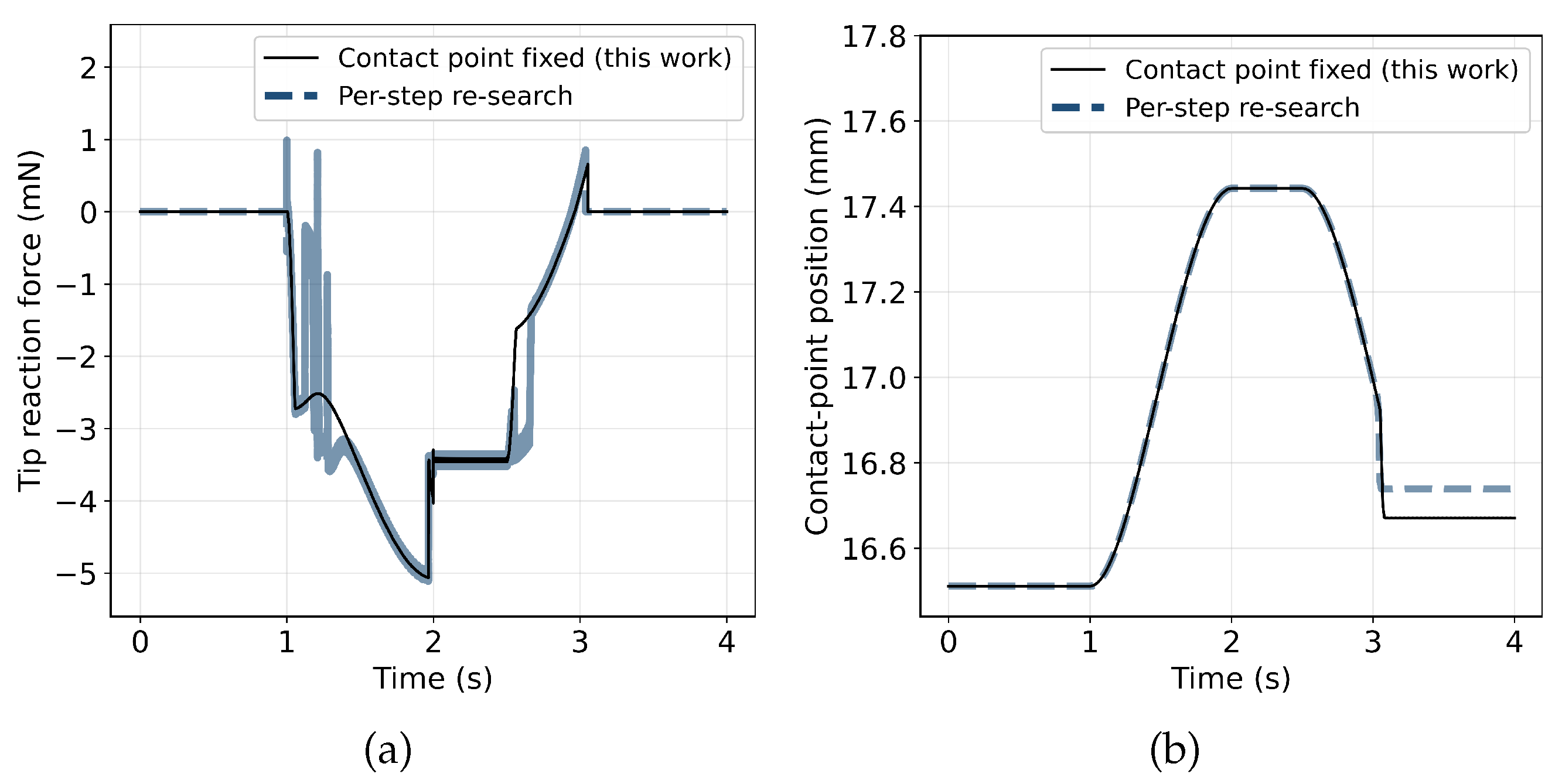
The contact-point treatment of Section 2.3 and the method that re-searches the contact point at every time step were compared under the geometry and operating conditions of this paper (steel, ϕ 45 ° / D 0.142 / μ 0.3 ). The re-search produced an oscillation band ( 0.58 + 0.74 mN) in the tip reaction force during incursion, whereas fixing the contact point maintained a smooth curve (Figure 2a). The high-frequency-noise index of the reaction force (the standard deviation of the second difference) was 2.11 × 10 5 when the contact point was fixed versus 1.89 × 10 4 for the re-search, i.e., about 9 times smaller. The contact-point position tracks the same shaft motion for both methods (Figure 2b), confirming that fixing the contact point removes the reaction-force oscillation without altering the contact kinematics.

4.4. Comparison with the Prior Study

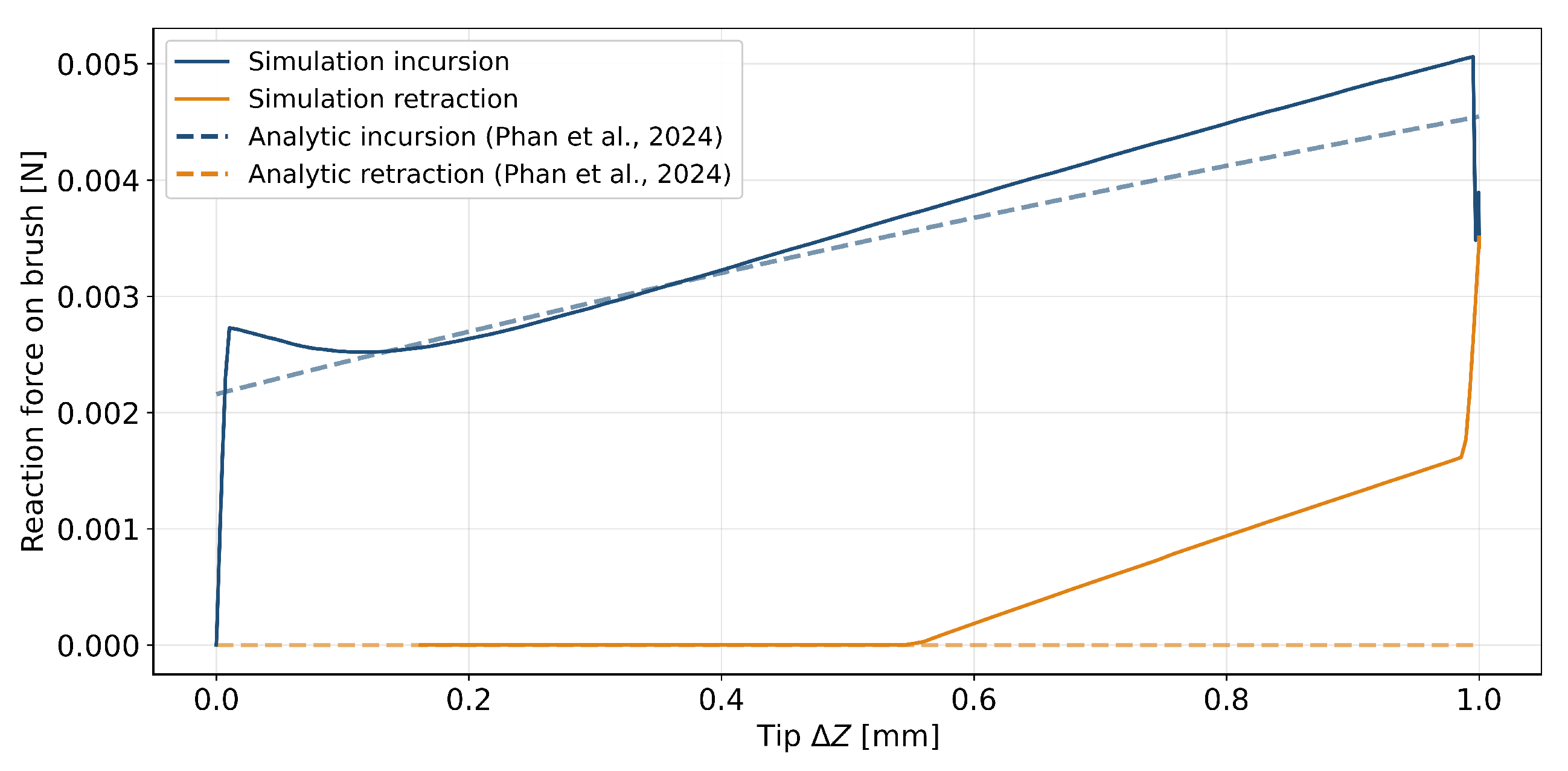
The developed analysis result was compared with the analytical curve of the prior study [11] under identical geometry and load conditions at a friction coefficient of 0.3 (Figure 3). The prior study regards the bristle as an elastic beam and, accounting for the Coulomb friction of the shaft and backing and the axial pressure load, computes the incursion and retraction reaction-force curves analytically; during retraction, when the contact normal force falls to zero or below, the contact is treated as lost (N clamped to 0 when N ≤ 0), representing hang-up. By contrast, the simulation curve of this work is obtained by time-integrating the force-balance equations for the six-degree-of-freedom motion of the bristle nodes, jointly accounting for corotational large deformation, the stick–slip friction model, and the Lagrangian constraint at the contact point.
The two results agree in the magnitude and trend of the reaction force and reproduce the incursion–retraction asymmetry (frictional hysteresis) in both cases. However, the present dynamic analysis shows a nonlinear rise in the incursion curve and a gradual separation during retraction (contact vanishing at Δ Z 0.55 mm), whereas the analytical curve of the prior study shows a straight-line rise and immediate separation. The two curves separate for the following reasons. During incursion the imposed radial displacement is carried, through the lay angle, into circumferential motion as well, while the tangential contact evolves from sticking toward sliding so that the reaction force rises nonlinearly. When the imposed motion stops at the start of the hold phase, the tangential sliding velocity vanishes, and the friction state changes, producing the step-like reduction in the reaction force seen in the time history (Figure 4a). During retraction the friction reverses direction, and inertia, the equivalent damping, and the evolving friction state together delay the recovery of the bristle. Contact is consequently lost, while about 0.55 mm of radial displacement remains, and this is the hang-up. The analytical model of the prior study, by contrast, treats the bristle quasi-statically with Coulomb friction and removes the contact as soon as the normal force becomes non-positive, so it does not contain this time-dependent evolution of state. The physical interpretation of each phase is discussed further in Section 5.4.

4.5. Rotation Effect

Comparing the tip reaction force under non-rotating and rotating conditions, the peak of the tip reaction force during rotation decreases to 0.92 times (the reduction ratio) that of the non-rotating case. The rotor surface speed U is far above the characteristic transition velocity d v , so the tip contact remains in full sliding throughout and the result is insensitive to the particular value of U. Following the prior study [11], the tip–shaft friction coefficient is taken as the material value (0.3) for a stationary shaft and as 0.1 for a rotating one, so this ratio contains two effects. Repeating the rotating case with the material coefficient separates them: the circumferential realignment of the friction alone reduces the peak to 0.79 times, while the lower coefficient raises it by a factor of 1.16 ( 0.79 × 1.16 = 0.92 ).

4.6. Dynamic Behavior over One Cycle

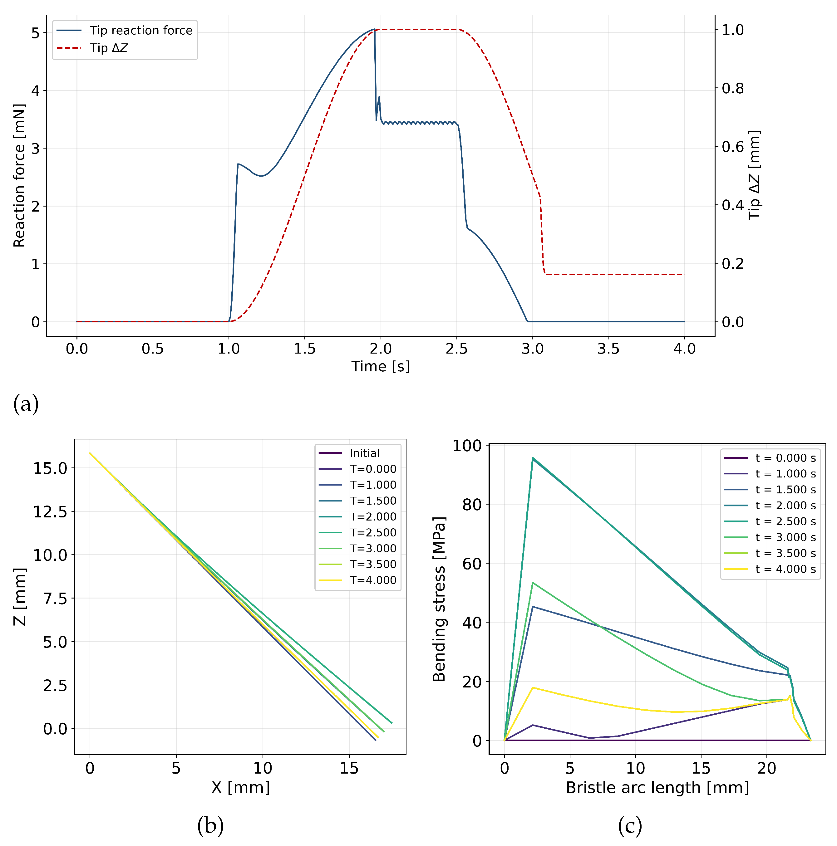
The dynamic behavior of the bristle over one cycle is presented through the tip reaction force, the radial displacement, the deformed shape, and the bending-stress distribution (Figure 4). Viewing the tip reaction force and the radial forced displacement Δ Z against time (Figure 4a), in the pressurization phase the tip is not in contact and the reaction force is zero; in the incursion phase the reaction force rises nonlinearly with the rotor incursion, reaching about 5.06 mN. On entering the hold phase the reaction force decreases in a step—this is the friction relaxation that appears when sliding stops. In the retraction phase the reaction force gradually decreases and vanishes to zero at about 2.96 s. At that instant the tip is still at Δ Z 0.55 mm, so it fails to follow the receding rotor and leaves a gap of that size (hang-up).
The deformed shape of the bristle is distinct in each phase (Figure 4b). During incursion the tip is pushed up radially and, owing to the lay angle, also moves circumferentially. The circumferential motion amounts to a displacement ratio of 0.93 with respect to the radial motion over the same interval (0.931 mm circumferentially for 1.000 mm radially). The axial component is below a fifty-second of the circumferential one, so the response is dominated by the xz plane. During retraction it does not return completely and stops at the hang-up position.
The bending-stress distribution supports this behavior from a stress viewpoint (Figure 4c). During the incursion and hold phases the stress is concentrated at the root, reaching about 96 MPa, whereas after the tip separates the root stress drops to about 18 MPa and the distribution flattens over the whole bristle. The physical mechanism of this phase-by-phase behavior is discussed in Section 5.4.

4.7. Admissibility of the Derived Friction Parameters

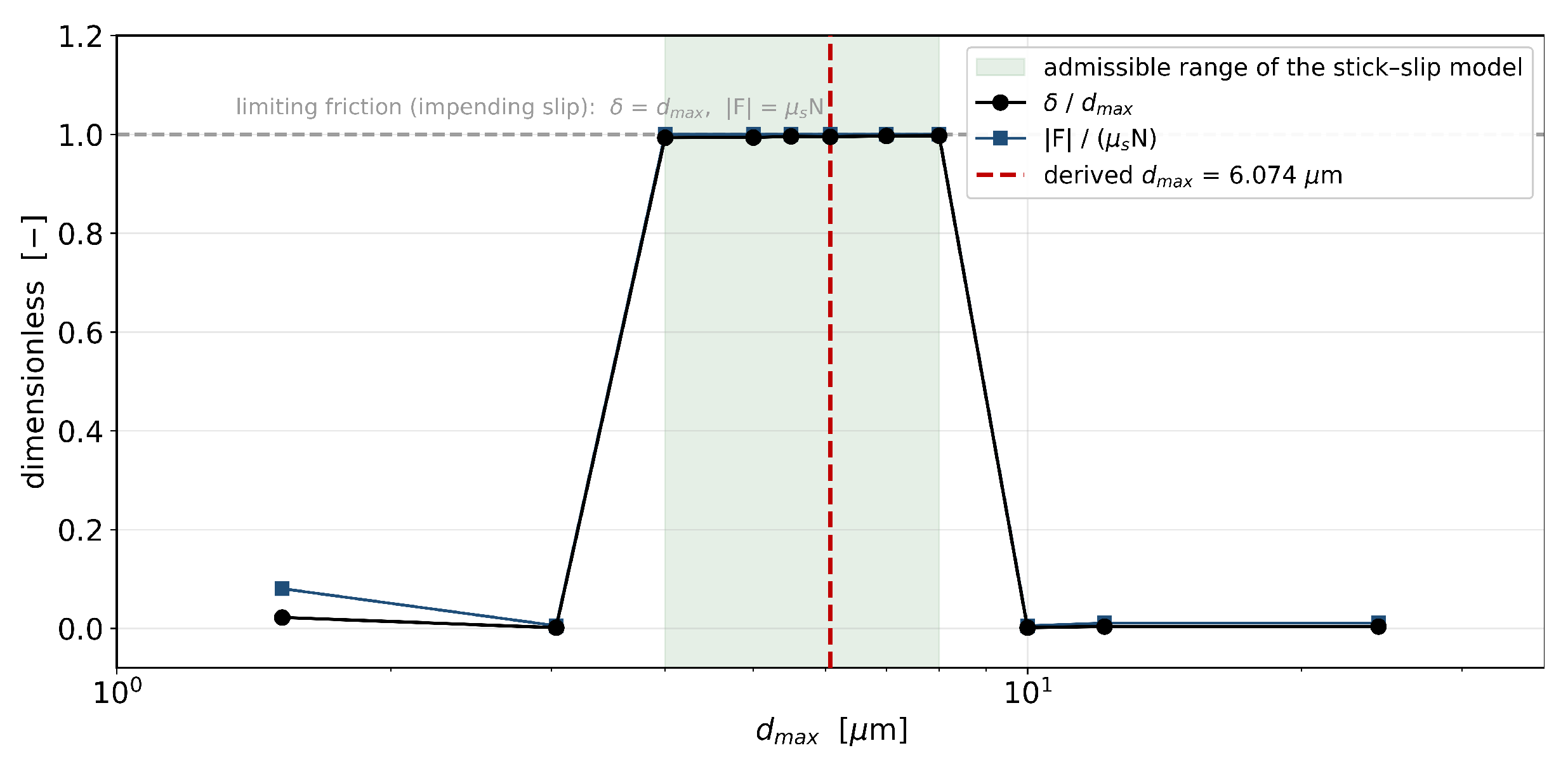
The state of the frictional contact is judged from two dimensionless ratios. The first is the tangential elastic-displacement ratio δ / d m a x . Here δ is the tangential elastic (pre-sliding) displacement accumulated at the contact point from the instant at which the tangential slip velocity vanishes; it is bounded above by the pre-slip limit d m a x , beyond which sliding sets in. The second is the friction saturation ratio | F | / ( μ s N ) , the tangential friction force normalized by the static-friction limit. Because the friction coefficient is a function of δ , the two ratios express the same contact state seen from the kinematic and the force side, and the state in which both reach unity is limiting friction, that is, impending slip.
When d m a x is varied from 1/8 to 4 times the derived value, the stick–slip behavior in which the contact reaches this limit and then transitions to sliding was obtained only for d m a x = 4–8 μ m (shaded band in Figure 5). Below this range the contact becomes overly stiff, the stuck state is not sustained and chatter appears; above it the pre-sliding displacement is too large and the accumulated elastic displacement is not retained. The value 6.07 μ m derived from the geometry and material properties (red dashed line in Figure 5) lies within 7% of the logarithmic center of this range, and at that point δ / d m a x = 0.995 and | F | / ( μ s N ) = 1.000, so the contact reaches the limiting friction state exactly. That is, the value derived from geometry and material properties alone coincides with the value the contact actually uses. The tip reaction-force peak, by contrast, converges over a wider range of d m a x because the reaction peak is set by the stiffness during incursion irrespective of whether the contact reaches the limit.

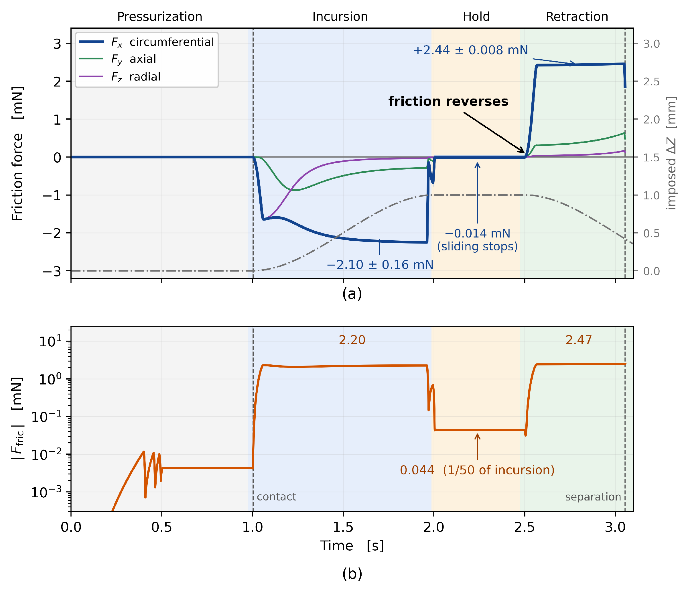
4.8. Time History and Reversal of the Friction Force

The behavior presented in the preceding sections through the reaction force, the deformed shape and the stress is confirmed here by the time history of the friction force itself (Figure 6). At the contact between the bristle and the backing ring, the circumferential component holds at 2.10 ± 0.16 mN during incursion and changes sign to + 2.44 ± 0.008 mN during retraction. The reversal occurs when the direction of the rotor motion changes, and the magnitudes before and after are comparable. During the hold phase the circumferential component is 0.014 mN, and the magnitude of the friction force is 0.044 mN, a fiftieth of its value during incursion; the friction force itself thus exhibits the relaxation toward the sticking state once the imposed motion stops and the tangential sliding vanishes.
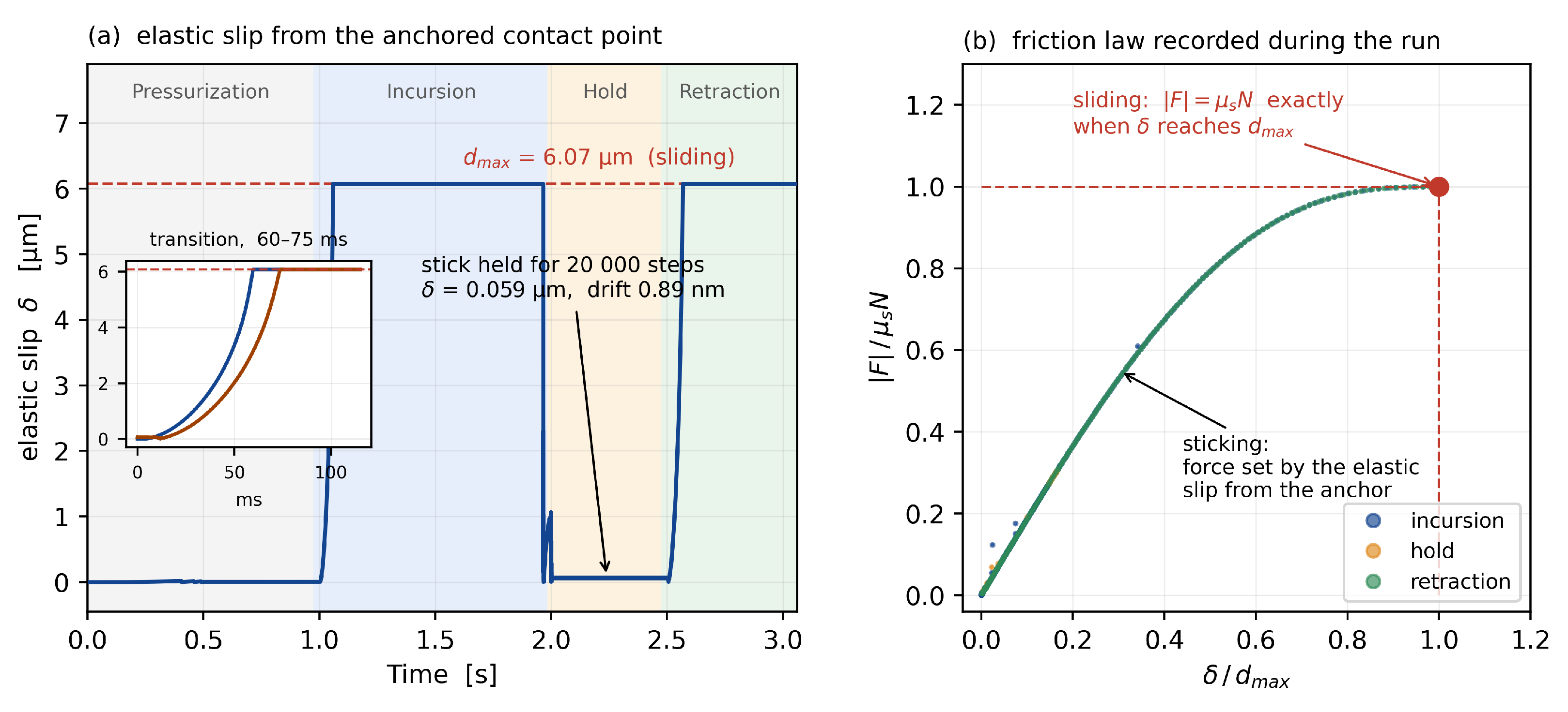
The sticking state is sustained by the tangential elastic displacement δ accumulated at the contact point. Over the 20,000 time steps of the hold phase, δ remains at 0.059 μ m with a variation of 0.89 nm, so sticking is maintained until slip begins, however many time steps are traversed. The transition from sticking to sliding develops over 60–75 ms and is not treated as a discontinuous switch of state.

4.9. Elastic Slip at the Anchored Contact Point and the Friction Law

Section 4.7 showed, through the end values of the two dimensionless ratios, that the derived d m a x coincides with the value the contact actually uses. Here we follow how that state develops in time (Figure 7). The tangential elastic displacement δ is measured from a reference point anchored at the contact, and that anchor does not move at any time during the analysis.
During pressurization δ is zero, and during incursion and retraction it saturates at d m a x = 6.07 μ m so that the contact is sliding (Figure 7a). During the hold phase δ relaxes to 0.059 μ m and the contact returns to sticking; that state is maintained for 20,000 time steps while δ varies by 0.89 nm, so sticking is held until slip begins however many time steps are traversed. The transition from sticking to sliding develops over 60–75 ms and is not treated as a discontinuous switch of state (inset of Figure 7a).
When the friction saturation ratio is plotted against the tangential elastic displacement ratio, the incursion, hold and retraction phases collapse onto a single curve (Figure 7b). The deviation between incursion and retraction stays within 0.97% of μ s N , and | F | / ( μ s N ) reaches 1.000 exactly when δ reaches d m a x . The curve is not a plot of the model expression but of the values recorded during the analysis. The tangential friction force in this model is therefore set by the elastic state of the contact alone, and the two parameters of Section 2.2 follow from that state.

5. Discussion

5.1. Equivalent Representation of Bristle-Pack Energy Dissipation

The results of Section 4 show that the choice of the damping coefficient governs both the physical fidelity and the stability of the analysis. With the material damping of a single bristle alone ( β 1 × 10 5 , ζ 0.6 % ), the analysis completes, but a high-frequency oscillation remains in the contact reaction force, its noise index reaching about 90 times that obtained with the inter-bristle friction damping; removing the damping entirely raises the oscillation to about 300 times and overestimates the peak reaction force by more than a factor of four. In contrast, the damping grounded in inter-bristle friction ( β = 1.617 × 10 4 , ζ = 9.5 % ) lowers the oscillation to the level of the built-in beam. The purely numerical stabilization value ( β = 4 × 10 4 , ζ = 23.5 % ) is also stable but has no physical basis. The damping of a brush-seal bristle pack is governed primarily by the dry (Coulomb) friction between bristles and between the bristles and the backing ring rather than by open-flow aerodynamics, consistent with the structural loss factor measured by Delgado and San Andrés [14]. The measured pack loss factor therefore provides an experimentally grounded scale for the dissipation that this reduced-order model requires, and damping set to that scale simultaneously suppresses the nonphysical high-frequency contact oscillation. The term is, however, an equivalent representation of pack-level dissipation rather than a direct model of the local dry friction, and its range of validity should be read together with the limitations of Section 5.5.

5.2. Mechanism of the Reaction-Force Reduction During Rotation

The reduction in the tip reaction force during rotation (Section 4.5) arises from a three-dimensional redistribution of the direction of the friction force. Without rotation, the tip slip is confined to the radial direction (incursion–retraction), so the friction force is added fully to the radial reaction. During rotation, the rotor surface always slides circumferentially, so the direction of the friction force—whose magnitude is limited to μ N —is realigned circumferentially. As a result the radial component of the friction force decreases, and the radial reaction loop shrinks; at an identical friction coefficient this realignment alone reduces the peak to 0.79 times (Section 4.5). The lower tip coefficient adopted for a rotating shaft acts in the opposite sense and returns part of that reduction, so the ratio observed under the operating condition is 0.92. The analytical, quasi-static model of the prior study does not include a circumferential degree of freedom, so this realignment does not appear; it is additional information provided by the present three-dimensional formulation.

5.3. Choice of the Beam Formulation

The incremental corotational formulation is not introduced here as a new beam theory; standard corotational formulations are well established for geometrically nonlinear beam analysis [22]. Its role in the present work is practical and methodological. The built-in beam is equally accurate but does not act on an element-level damping matrix (Section 3.2), so it cannot carry the inter-bristle friction damping grounded in the measured loss factor, whereas the incremental corotational beam can.

5.4. Hysteresis Difference Due to the Dynamic Behavior

The reason the hysteresis in Section 4.4 differs from the analytical curve of the prior study is that the friction state changes with time over the whole cycle. This time-dependent transition appears with three-dimensional multibody dynamics and a stick–slip friction model, and the time histories of reaction force, shape, and stress in Section 4.6 (Figure 4) are its evidence. The mechanism of each phase is as follows.
The phase-by-phase interpretation is supported quantitatively by the calculated histories of Figure 4. During incursion the reaction force rises to about 5.06 mN. On entering the hold phase the reaction force decreases even though the imposed radial displacement no longer changes, which shows that the change in force comes from the evolving contact and friction state rather than from additional imposed displacement. During retraction the reaction force reaches zero at about 2.96 s, while about 0.55 mm of radial displacement remains; this residual displacement is the direct numerical measure of the predicted hang-up.
The structural response indicates the same transition independently. The root-concentrated bending stress reaches about 96 MPa during incursion and hold, and after the tip separates it falls to about 18 MPa while the distribution flattens along the bristle. The reaction-force history, the residual displacement, the deformed shape, and the stress redistribution thus point consistently to the same transition.
During pressurization the tip is not yet in contact with the rotor, and the pressure load seats the bristle against the backing ring, setting the baseline of the reaction. During incursion the tip is pushed up radially, and because of the lay angle this radial motion is also carried into circumferential motion; such three-dimensional coupling does not appear in a planar model without a circumferential degree of freedom. At the same time the tip friction changes from static (stick) to slip, and the reaction rises nonlinearly.
During the hold phase, when the rotor stops and the tip no longer slides, the kinetic friction relaxes toward static friction and the reaction decreases somewhat. This relaxation—the recovery of the contact state when sliding stops (rate-and-state friction [16,17])—arises naturally in a stick–slip friction model that judges the state by deformation (force). In machine friction the same behavior is described as a rise of the static friction with the dwell time spent in the stuck condition, together with a phase lag of the friction behind a change in sliding velocity [25]. Coulomb friction, which carries only a sign, does not distinguish static from kinetic states, so this relaxation does not appear.
During retraction the friction reverses direction and the bristle cannot fully follow the withdrawing rotor, so it separates from the rotor before reaching the target position and leaves a gap (hang-up). That the friction state evolves with time is confirmed directly by the history of the friction force at the bristle–backing contact (Section 4.8, Figure 6): the sign of the circumferential component is opposite between incursion and retraction, and during the hold phase the magnitude falls to a fiftieth of its value during incursion. Because the analytical model of the prior study removes the contact when the normal force falls to zero or below, its retraction follows a straight line, whereas the dynamic analysis—through inertia, damping, and the temporal transition of friction—shows a gradual, incomplete recovery. The flattening of the root-concentrated bending stress upon tip separation is the stress-side expression of the same behavior.
In short, the difference between the two hystereses stems from a difference in modeling perspective. The prior study [11] provides an efficient analytical description using a two-dimensional elastic beam and quasi-static Coulomb friction, while the present work solves the six-degree-of-freedom motion of the bristle through force balance and thereby captures the three-dimensional large deformation, inertia, damping, and the temporal stick–slip transition of friction together. Because real friction moves between static and kinetic states and leaves a history, the dynamic analysis additionally describes these in-cycle behaviors and complements the analytical perspective of the prior study. The enclosed area of the frictional hysteresis loop corresponds to the mechanical energy dissipated per cycle, which is ultimately converted to frictional heat. That this dissipation leads to heating and wear in an actual brush seal has been observed in tests that measured the hysteresis, the leakage, and the temperature rise at the bristle tips together [19]. The present model does not compute this thermal conversion; a full thermodynamic energy budget and the resulting temperature field and thermal stress are left to future work.

5.5. Limitations

This work has the following limitations. First, the accuracy check is limited to implementation verification against the built-in beam and cross-comparison with an existing analytical model [11]; direct comparison with experiments measuring the leakage, reaction force, and wear of an actual brush seal (validation) is left to future work once test data are available. Second, the analysis addresses a representative single bristle, and the dissipation arising from the surrounding bristles is represented by an equivalent Rayleigh damping calibrated to a measured loss factor (Section 2.4). That measurement was made on a shoed brush seal excited without shaft rotation [14], so its configuration and operating conditions differ from those of the present case, and what is taken from it is the magnitude of the pack-level dissipation. The present model therefore does not resolve individual stick–slip events between bristles, the local redistribution of contact force, amplitude-dependent Coulomb dissipation, or the spatial distribution of frictional heat. A multi-bristle analysis that explicitly solves the inter-bristle contact is a future task. Third, the characteristic velocity d v loses its role under the present verification condition μ s = μ d , so the Stribeck transition for differing coefficients requires separate study. Fourth, the work is limited to an isothermal, mechanical analysis; the bristle temperature field, frictional heat, fatigue life, and thermo-mechanical coupling are treated in future work. Fifth, the tangential contact stiffness k t was evaluated with a reduced three-node linear finite-element model and a nominal contact location (H), so the values of d m a x and d v carry an uncertainty. Increasing the node count or accounting for the moving contact point ( H H + d H ) would shift both values. The tip reaction force is, however, insensitive to d m a x over a wide range, and since d m a x 1 / k t the admissible range of Section 4.7 (0.66–1.32 times the derived value) corresponds to k t = 563–1127 N/m. The two independent estimates of k t , 723 N/m and 876 N/m give d m a x equal to 1.03 and 0.85 times the derived value, and both lie inside that range, so the results are unaffected. A quoted hang-up magnitude should nevertheless be accompanied by the k t on which it rests.

6. Conclusions

The large deformation, friction, contact, and dynamic response of brush-seal bristles are directly related to seal performance and life. Previous studies have established three-dimensional structural models, transient analyses, and increasingly detailed models of inter-bristle interaction. The present work addresses a complementary problem: treating stick–slip parameterization, constraint-based contact, an equivalent representation of pack-level dissipation, and the numerical treatment of the contact point consistently within a reduced-order open-source multibody formulation.
The proposed methodology is organized as follows. An incremental corotational beam with an analytic tangent stiffness based on a standard corotational formulation was implemented in C++ and Python within the open-source multibody dynamics system Exudyn, and the three-dimensional dynamics of a bristle, including geometrically nonlinear large deformation, was analyzed. Instead of Coulomb friction, a stick–slip friction model that treats the stick–slip transition continuously was applied, and the friction parameters d m a x and d v , which commercial codes leave to user input, were derived from the elastic energy of the contact point. The contact was formulated with a Lagrangian constraint at the contact point, and the dissipation arising from the surrounding bristles was represented by an equivalent Rayleigh damping calibrated to a measured loss factor.
In verification, the incremental corotational beam agreed with the built-in Exudyn beam to within 0.02% in tip displacement and 0.03% in shape, confirming the correctness of the implementation, and the friction analysis with d m a x and d v derived from the elastic energy was shown to converge stably. It was also cross-validated against the prior study [11] at a friction coefficient of 0.3. Fixing the contact point reduced the numerical oscillation of the reaction force by about 9 times relative to re-searching the contact point, and the damping that accounts for inter-bristle friction produced a dynamic response different from that with material damping alone, confirming that the damping from bristle-pack interaction is significant for the dynamics. In particular, during rotation the tip friction realigns circumferentially, and the tip reaction force decreases to 0.92 times that of the non-rotating case; at an identical friction coefficient the realignment alone accounts for a reduction to 0.79 times, which shows a three-dimensional redistribution of the friction force that is absent from the planar quasi-static model compared in Section 4.4.
The present work is restricted to a mechanical analysis and does not compute the leakage flow. The reaction force, hang-up displacement, contact state, and bending stress obtained here can nevertheless serve as mechanical state variables that link the seal geometry and the operating conditions to leakage, frictional heating, wear, and fatigue life. The coupling in which the clearance that follows from the deformation and the contact is passed to a leakage-flow model, and the resulting aerodynamic loading is returned to the bristle model, is treated in work being prepared for separate publication; the questions it raises are of a different kind from those addressed here and could not be treated adequately within the scope of this paper. A complementary route has been followed elsewhere, in which the loss of rotor contact under pressure loading is solved as a quasi-static equilibrium and the clearance so produced, together with the sharp increase in leakage that follows, or blow-out, is computed [31]. This direction is in line with recent work that combines a two-dimensional leakage-flow model with a three-dimensional bristle mechanics model [20], and tests in which the hysteresis, the leakage, and the frictional heating were measured together [19] provide experimental grounds for the link. Design parameters could then be assessed not only for leakage reduction but also with respect to excessive contact loading and service life. A second direction concerns the thermal limit of the bristle. The frictional work done at the rotor is delivered into a slender bristle of small thermal capacity, and the leakage flow is the path by which that heat is carried away, so the temperature the bristle reaches is set by the coupling between the two. That temperature in turn changes the problem solved here since thermal expansion of the bristle alters the contact and the stress distribution that the present analysis resolves. The formulation is accordingly being extended so that the beam carries thermal expansion, and the temperature field, the frictional heat input and the fatigue life that follows are treated together with the leakage flow rather than as a parametric addition to the present model; this forms part of the separate publication noted above. The sensitivity of the design parameters that cause hang-up remains a further extension.

Author Contributions

Conceptualization, J.-H.K., Y.C.K. and S.M.M.; methodology, J.-H.K. and Y.C.K.; software, J.-H.K.; validation, J.-H.K.; formal analysis, J.-H.K.; investigation, J.-H.K.; resources, Y.C.K.; writing—original draft preparation, J.-H.K.; writing—review and editing, J.-H.K. and Y.C.K.; supervision, Y.C.K.; project administration, Y.C.K.; funding acquisition, Y.C.K. All authors have read and agreed to the published version of the manuscript.

Funding

This research was funded by the Korea Research Institute for Defense Technology Planning and Advancement (KRIT) under the Defense Acquisition Program Administration (DAPA) for the research project titled “Design Technology of a Tailored Seal for Increasing Efficiency of Aviation Gas Turbines,” grant number KRIT-CT-23-040.

Data Availability Statement

The data presented in this study are available on request from the corresponding author due to restrictions associated with the defense-related research project under which the data were generated.

Acknowledgments

During the preparation of this manuscript, the authors used Claude Opus 5 (Anthropic) as a coding and language-assistance tool. The structure of the paper, the propositions it advances, and the conclusions drawn from the results were set by the authors, who directed the work throughout; the tool was used to search the literature and verify bibliographic records, to implement and debug the analysis and plotting scripts, to organize the computed output for examination, and to draft and edit portions of the English text. Every statement was checked by the authors against the computed graphs and numbers before it was retained. The authors have reviewed and edited all AI-assisted output and take full responsibility for the accuracy, integrity, and content of this publication.

Conflicts of Interest

The authors declare no conflicts of interest.

Nomenclature

Coordinate frame: x circumferential, y axial (pressure-difference direction), z radial. In GJ, J is the St. Venant torsion constant (distinct from the Jacobian J). Subscripts/operators: (·)0 frozen at previous converged instant; (·)t tangential; (·)s, (·)d static/kinetic; ( · ^ ) unit vector; ( · · ) time derivative.
SymbolDefinitionSymbolDefinition
Abristle cross-sectional area (m2)Bstrain–displacement matrix
CRayleigh damping matrix, C = β K (N·s/m)
Dbristle diameter (m)EYoung’s modulus (Pa)
Ffriction force magnitude, F = μ N (N) G , G * shear/effective shear modulus (Pa)
Hexposed length (m)Iidentity matrix
I y , I z second moments of area (m4)Janalytic tangent stiffness (Jacobian)
K , K local , K 6 , K 0 global/element/sectional/frozen stiffness (N/m)Lbristle free length (m)
Mmass matrix (kg)
N , N i contact normal force = λ /nodal share (N)Ptangential projector
Q c corotational frame R i , R node nodal rotation matrix
S ( s ) fifth-order shape polynomial STEP 5 C 2 -smooth step function
Urotor surface speed (m/s) Δ Z radial forced displacement (m)
acontact radius (m) d m a x maximum pre-slip deformation (m)
d v characteristic transition velocity (m/s) e x , e y , e z corotational frame basis
f t , f int , f ext tangential friction/internal/external force (N) f 1 first bending natural frequency (Hz)
h 0 , h 1 STEP5 end values
k t tangential contact stiffness (N/m) , 0 current/reference element length (m)
mfriction-element equivalent mass (kg) n ^ contact normal unit vector
p node , p ref position vectors (m) q , q def nodal coordinates, deformation measure
sSTEP5 normalized coordinate
ttime (s)
u t , u sl tangential displacement/slip part (m) v t , v rel slip/relative velocity (m/s)
x , y , z coordinates (circumferential/axial/radial) (m)
Greek symbols
SymbolDefinitionSymbolDefinition
β Rayleigh damping coefficient (s) γ structural loss factor
Δ pre-slip elastic deformation (m) δ * Cattaneo–Mindlin displacement (m)
ζ n modal damping ratio λ contact Lagrange multiplier = N (N)
μ , μ s , μ d friction/static/kinetic coefficient ν Poisson’s ratio
ρ density (kg/m3) ϕ lay angle (°)
Φ , Φ q constraint equations/constraint Jacobian
χ ( v t ) smooth velocity-sign indicator ψ elastic strain energy (J)
ω n natural angular frequency (rad/s)

References

  1. Bayley, F.J.; Long, C.A. A Combined Experimental and Theoretical Study of Flow and Pressure Distributions in a Brush Seal. J. Eng. Gas. Turbines Power 1993, 115, 404–410. [Google Scholar] [CrossRef] [Scilit]
  2. Chupp, R.E.; Hendricks, R.C.; Lattime, S.B.; Steinetz, B.M. Sealing in Turbomachinery; NASA/TM-2006-214341; NASA Glenn Research Center: Cleveland, OH, USA, 2006. [Google Scholar]
  3. Chupp, R.E.; Hendricks, R.C.; Lattime, S.B.; Steinetz, B.M. Sealing in Turbomachinery. J. Propuls. Power 2006, 22, 313–349. [Google Scholar] [CrossRef] [Scilit]
  4. Crudgington, P.; Bowsher, A. Brush Seal Blow Down. In Proceedings of the 39th AIAA/ASME/SAE/ASEE Joint Propulsion Conference and Exhibit, Huntsville, AL, USA, 20–23 July 2003. AIAA Paper 2003-4697. [Google Scholar] [CrossRef] [Scilit]
  5. Crudgington, P.F.; Bowsher, A. Brush Seal Pack Hysteresis. In Proceedings of the 38th AIAA/ASME/SAE/ASEE Joint Propulsion Conference and Exhibit, Indianapolis, IN, USA, 7–10 July 2002. AIAA Paper 2002-3794. [Google Scholar] [CrossRef] [Scilit]
  6. Duran, E.T.; Aksit, M.F.; Ozmusul, M. Brush Seal Structural Analysis and Correlation with Tests for Turbine Conditions. J. Eng. Gas. Turbines Power 2016, 138, 052502. [Google Scholar] [CrossRef] [Scilit]
  7. Demiroglu, M.; Gursoy, M.; Tichy, J.A. An Investigation of Tip Force Characteristics of Brush Seals. In Proceedings of the ASME Turbo Expo 2007: Power for Land, Sea and Air, Montreal, QC, Canada, 14–17 May 2007. GT2007-28042. [Google Scholar] [CrossRef] [Scilit]
  8. Stango, R.J.; Zhao, H.; Shia, C.Y. Analysis of Contact Mechanics for Rotor–Bristle Interference of Brush Seal. J. Tribol. 2003, 125, 414–421. [Google Scholar] [CrossRef] [Scilit]
  9. Duran, E.T. Brush Seal Contact Force Theory and Correlation with Tests. Alex. Eng. J. 2022, 61, 2925–2938. [Google Scholar] [CrossRef] [Scilit]
  10. Duran, E.T. Operational Modal Analyses of Brush Seals and Seating Load Simulations. J. Eng. Gas. Turbines Power 2022, 144, 071005. [Google Scholar] [CrossRef] [Scilit]
  11. Phan, H.M.; Pekris, M.J.; Chew, J.W. Insights into Frictional Brush Seal Hysteresis. J. Eng. Gas. Turbines Power 2024, 146, 081010. [Google Scholar] [CrossRef] [Scilit]
  12. FunctionBay, I. RecurDyn Solver Theoretical Manual; FunctionBay: Seongnam, Republic of Korea, 2023. [Google Scholar]
  13. Software, M.S.C. Adams—Multibody Dynamics Simulation, Theory Manual; Hexagon AB: Stockholm, Sweden, 2023. [Google Scholar]
  14. Delgado, A.; San Andrés, L. Identification of Structural Stiffness and Damping Coefficients of a Shoed-Brush Seal. J. Vib. Acoust. 2007, 129, 648–655. [Google Scholar] [CrossRef] [Scilit]
  15. Vanegas-Useche, L.V.; Abdel-Wahab, M.M.; Parker, G.A. Determination of the Rayleigh Damping Coefficients of Steel Bristles and Clusters of Bristles of Gutter Brushes. DYNA 2015, 82, 230–237. [Google Scholar] [CrossRef] [Scilit]
  16. Dieterich, J.H. Modeling of Rock Friction: 1. Experimental Results and Constitutive Equations. J. Geophys. Res. Solid Earth 1979, 84, 2161–2168. [Google Scholar] [CrossRef] [Scilit]
  17. Ruina, A. Slip Instability and State Variable Friction Laws. J. Geophys. Res. Solid Earth 1983, 88, 10359–10370. [Google Scholar] [CrossRef] [Scilit]
  18. Phan, H.M.; Pekris, M.J.; Chew, J.W.; Greenslade, T.J. Modeling of Frictional Interbristle Contact in Brush Seals with Shaft Radial Movements. J. Eng. Gas. Turbines Power 2025, 147, 091015. [Google Scholar] [CrossRef] [Scilit]
  19. Li, P.; Hu, Y.; Hou, Y.; Ji, H. Experimental Investigation on Leakage and Frictional Heat Generation Characteristics of Low Hysteresis Brush Seals. J. Eng. Gas. Turbines Power 2025, 147, 021002. [Google Scholar] [CrossRef] [Scilit]
  20. Li, Z.; Wu, S.; Xiong, L.; Li, J. A Multi-Physics Behavior Assessment Framework for Brush Seals: Effects of Geometry Parameters. J. Turbomach. 2026, 148, 091014. [Google Scholar] [CrossRef] [Scilit]
  21. Gerstmayr, J. Exudyn: A C++-Based Python Package for Flexible Multibody Systems. Multibody Syst. Dyn. 2024, 60, 533–561. [Google Scholar] [CrossRef] [Scilit]
  22. Felippa, C.A.; Haugen, B. A Unified Formulation of Small-Strain Corotational Finite Elements: I. Theory. Comput. Methods Appl. Mech. Eng. 2005, 194, 2285–2335. [Google Scholar] [CrossRef] [Scilit]
  23. Crisfield, M.A. A Consistent Co-Rotational Formulation for Non-Linear, Three-Dimensional, Beam-Elements. Comput. Methods Appl. Mech. Eng. 1990, 81, 131–150. [Google Scholar] [CrossRef] [Scilit]
  24. Iwan, W.D. A Distributed-Element Model for Hysteresis and Its Steady-State Dynamic Response. J. Appl. Mech. 1966, 33, 893–900. [Google Scholar] [CrossRef] [Scilit]
  25. Armstrong-Hélouvry, B.; Dupont, P.; Canudas de Wit, C. A Survey of Models, Analysis Tools and Compensation Methods for the Control of Machines with Friction. Automatica 1994, 30, 1083–1138. [Google Scholar] [CrossRef] [Scilit]
  26. Dahl, P.R. Solid Friction Damping of Mechanical Vibrations. AIAA J. 1976, 14, 1675–1682. [Google Scholar] [CrossRef] [Scilit]
  27. Canudas de Wit, C.; Olsson, H.; Åström, K.J.; Lischinsky, P. A New Model for Control of Systems with Friction. IEEE Trans. Autom. Control 1995, 40, 419–425. [Google Scholar] [CrossRef] [Scilit]
  28. Berger, E.J. Friction Modeling for Dynamic System Simulation. Appl. Mech. Rev. 2002, 55, 535–577. [Google Scholar] [CrossRef] [Scilit]
  29. Mindlin, R.D. Compliance of Elastic Bodies in Contact. J. Appl. Mech. 1949, 16, 259–268. [Google Scholar] [CrossRef] [Scilit]
  30. Johnson, K.L. Contact Mechanics; Cambridge University Press: Cambridge, UK, 1985. [Google Scholar] [CrossRef] [Scilit]
  31. Mehdi, S.M.; Kim, J.-H.; Kim, Y.C. Analysis of Deformation, Blow-Out Mechanism, and Leakage Behavior of Brush Seals Under Distributed Pressure Loading. Lubricants 2026, 14, 321. [Google Scholar] [CrossRef] [Scilit]
Figure 1. Single-bristle model. (a) Bristle pack (z–y plane); (b) bristle with symbols (z–y plane); (c) lay angle (z–x plane).
Lubricants 14 00354 g001
Figure 2. Contact point fixed versus per-step re-search. (a) Tip reaction-force time history; (b) contact-point position.
Lubricants 14 00354 g002
Figure 3. Tip reaction force versus displacement, simulation and analysis ( μ = 0.3 ). The analytical curves are computed from the formulation of Phan et al. [11] for the geometry and loading of the present work.
Lubricants 14 00354 g003
Figure 4. Dynamic behavior over one cycle. (a) Time history of the tip reaction force and the radial displacement Δ Z —the reaction peak during incursion, the step on entering the hold phase, the instant at which the reaction force reaches zero, and the radial displacement still remaining at that instant (the hang-up) are read from this panel; (b) deformed bristle shapes by phase (xz plane); (c) bending-stress distribution along the bristle by phase—the root concentration during incursion and hold, and its flattening after tip separation, are read from this panel. All values quoted in Section 5.4 are taken from this figure.
Lubricants 14 00354 g004
Figure 5. Admissibility of the derived d m a x —dimensionless contact-state ratios versus d m a x .
Lubricants 14 00354 g005
Figure 6. Friction force at the bristle–backing contact. (a) Circumferential, axial and radial components—the reversal of sign between incursion and retraction is read from this panel (the gray dash-dotted line is the imposed radial displacement Δ Z ); (b) magnitude of the friction force (logarithmic axis)—the relaxation during the hold phase is read from this panel.
Lubricants 14 00354 g006
Figure 7. Elastic slip at the anchored contact point and the friction law. (a) Elastic slip δ over the cycle—the anchor does not move; the sticking held during the hold phase and the transition developing over 60–75 ms (inset) are read from this panel; (b) friction law recorded during the analysis—that | F | / ( μ s N ) is a single-valued function of δ / d m a x is read from this panel.
Lubricants 14 00354 g007
Table 1. Geometry, material, and operating conditions.
CategorySymbolQuantityValue
Geometry ϕ Lay angle45°
LFree length23.35 mm
HExposed length1.524 mm
DBristle diameter0.142 mm
MaterialEYoung’s modulus206.8 GPa
ν Poisson’s ratio0.3
GShear modulus79.5 GPa
ρ Density8000 kg/m3
μ Friction coefficient (material; 0.1 at the tip when the shaft rotates)0.3
Operation Δ Z Radial forced displacement1.00 mm
Pressurization time/pressure ramp1.0 s/0.5 s
Analysis time (1 cycle)3.0 s
Table 2. Native vs. incremental corotational beam.
QuantityNative (Geometrically Exact)Incremental CorotationalDifference
Tip displacement 6.68530 × 10 4 m 6.68431 × 10 4 m0.02%
Bristle shape (18 nodes)referencecompared0.03%
Contact λ 6.64 × 10 5 6.84 × 10 5 ~3%
Disclaimer/Publisher’s Note: The statements, opinions and data contained in all publications are solely those of the individual author(s) and contributor(s) and not of MDPI and/or the editor(s). MDPI and/or the editor(s) disclaim responsibility for any injury to people or property resulting from any ideas, methods, instructions or products referred to in the content.