Article

A Method for Predicting Motion Error of Internal Feedback Hydrostatic Turntable Under Eccentric Load

1
College of Mechanical Engineering, Jiaxing University, Jiaxing 314001, China
2
Beijing Key Laboratory of Advanced Manufacturing Technology, Beijing University of Technology, Beijing 100124, China
3
Genertec Machine Tool Engineering Research Institute Co., Ltd., Beijing 100020, China
*
Author to whom correspondence should be addressed.
Lubricants 2026, 14(8), 323; https://doi.org/10.3390/lubricants14080323
Submission received: 4 July 2026 / Revised: 27 July 2026 / Accepted: 14 August 2026 / Published: 21 August 2026

Abstract

This paper proposes a method to analyze motion errors in a five-degree-of-freedom hydrostatic turntable with internal feedback under eccentric load. The motion error models of thrust and journal bearings are derived separately, revealing the mechanism of the influence of manufacturing errors of thrust plate and shaft on motion errors. The results demonstrate that the hydrostatic oil film exhibits an error averaging effect. When the amplitude of the mating surface error reaches 15 μm, the corresponding linear deviation of the turntable remains below 0.3 μm, indicating that the oil film can effectively suppress the transmission of manufacturing errors. However, the pressure oil film cannot completely balance the errors on the film binding surface, especially when the amplitude of the binding surface error is larger, resulting in a weaker ability of the oil film to balance.

1. Introduction

Hydrostatic bearings find broad application in precision and ultra-precision machine tools owing to their exceptional motion accuracy [1,2,3]. They are employed in diverse configurations, encompassing hydrostatic turntables, hydrostatic spindles, and hydrostatic guideways. The heightened precision of hydrostatic bearings predominantly results from the error-averaging phenomenon facilitated by the pressure oil film [4]. Notably, in recent years, numerous researchers have conducted investigations into the accuracy of hydrostatic bearings.
Zhang et al. [5] separately examined the journal and thrust bearing accuracy, devising a five-degree-of-freedom approximate accuracy model. This model facilitated the prediction of the motion accuracy for a hydrostatic turntable with an arbitrary number of recesses. Zha et al. [6,7] computed the axial runout error and angular error of the hydrostatic thrust bearing, taking into account the verticality and flatness errors of the component. Building upon this analysis, the precision design for hydrostatic thrust bearings was finalized. Zhang et al. [8,9,10] introduced a method for investigating the kinematic error of hydrostatic bearings. This method involved leveraging the equivalent cubic of the oil film thickness, establishing a relationship between the kinematic error and the structural parameters of the bearing. Zhang et al. [11] formulated a dynamic accuracy model for journal bearing. This model considered the roundness errors of both the bushing and shaft, resolves the dynamic equations, and investigates how rotational speed influences motion accuracy. Zhao et al. [12] developed a model for the bias load in a hydrostatic turntable, aiming to analyze how guideway contour errors affect its motion accuracy. Zhang et al. [13] devised a novel model for assessing the straightness and angular error of a closed hydrostatic guideway with four oil pads. Qi et al. [14] presented a method to assess the average impact of hydrostatic guideway errors, taking into account the three-dimensional contour error of the guideway. The study demonstrated that the contour error in both width and length directions of the hydrostatic guideway influences the motion error. In the study conducted by Zha et al. [15,16], a model for calculating motion errors was formulated for an open gantry hydrostatic guideway. The investigation examined both the straightness and linear displacement deviation of the guideway, and introduced a proposed strategy for error compensation. Niu et al. [17] proposed a method for predicting guide motion errors under uncertain thread friction coefficients. Michalec et al. [18] proposed a method for compensating errors in hydrostatic bearing through a multi-oil pad approach. An experimental device was constructed to substantiate the effectiveness of the multi-oil pad hydrostatic support, revealing noteworthy reductions in assembly and manufacturing errors. Shi et al. [19] applied kinematics theory to develop a model for analyzing motion errors in a closed hydrostatic guideway. The model’s validity was experimentally confirmed using an ultra-precision grinding machine. Liu et al. [20] examined the impact of tilt and thermal effects on the characteristics of oil film bearings in pads. Zhang et al. [21] explored the impact of rotational speed and external load on the error homogenization effect of hydrostatic sliding bearings. The findings revealed that the error homogenization coefficient was influenced by the interplay of rotational speed, external load, and roundness wave number. Xu et al. [22] introduced a compensation device for hydrostatic bearings employing piezoelectric ceramics, which improved the spindle rotation accuracy by master control. Fang et al. [23] formulated five-degree-of-freedom kinetic equations for both hydrostatic bearing and rotor. The study delved into the impact of rotor coaxiality errors on motion accuracy across various operating conditions. Cheng et al. [24] proposed a model to discern load errors, grounded in the deformation of a hydrostatic turntable subjected to a load. The investigation assessed the repercussions of load errors on machining accuracy. In our previous work [25,26], an equivalent hydraulic circuit model of the internally fed hydrostatic bearing was developed, and the operating mechanism of the internally fed bearing was systematically investigated. Building upon these findings, the present study extends the research scope to motion errors, aiming to establish a more comprehensive performance analysis framework for hydrostatic bearing systems.
In summary, previous studies have primarily focused on the kinematic errors of conventional hydrostatic bearings under the assumption that the magnitude and direction of the applied load remain constant. However, such assumptions may not fully represent the actual operating conditions of rotary tables subjected to eccentric loading, where the load action angle varies continuously with rotation and leads to coupled motion errors in multiple degrees of freedom. Furthermore, most existing models have been developed for conventional hydrostatic bearing configurations, while the motion error characteristics of internally fed hydrostatic bearings, which possess distinct pressure distribution and stiffness characteristics due to their internal feedback oil circuits, have rarely been investigated.
To address these limitations, this study develops a five-degree-of-freedom motion error model for an internally fed hydrostatic turntable by considering the variation in eccentric load angles during operation. A decoupled analysis strategy is established for thrust and journal bearings to investigate their individual and coupled contributions to the overall motion errors. The proposed model provides new insights into the influence of internal feedback characteristics and variable eccentric loading on hydrostatic turntable accuracy, offering theoretical guidance for improving the precision performance of hydrostatic support systems.

2. Theory

2.1. Accuracy Model

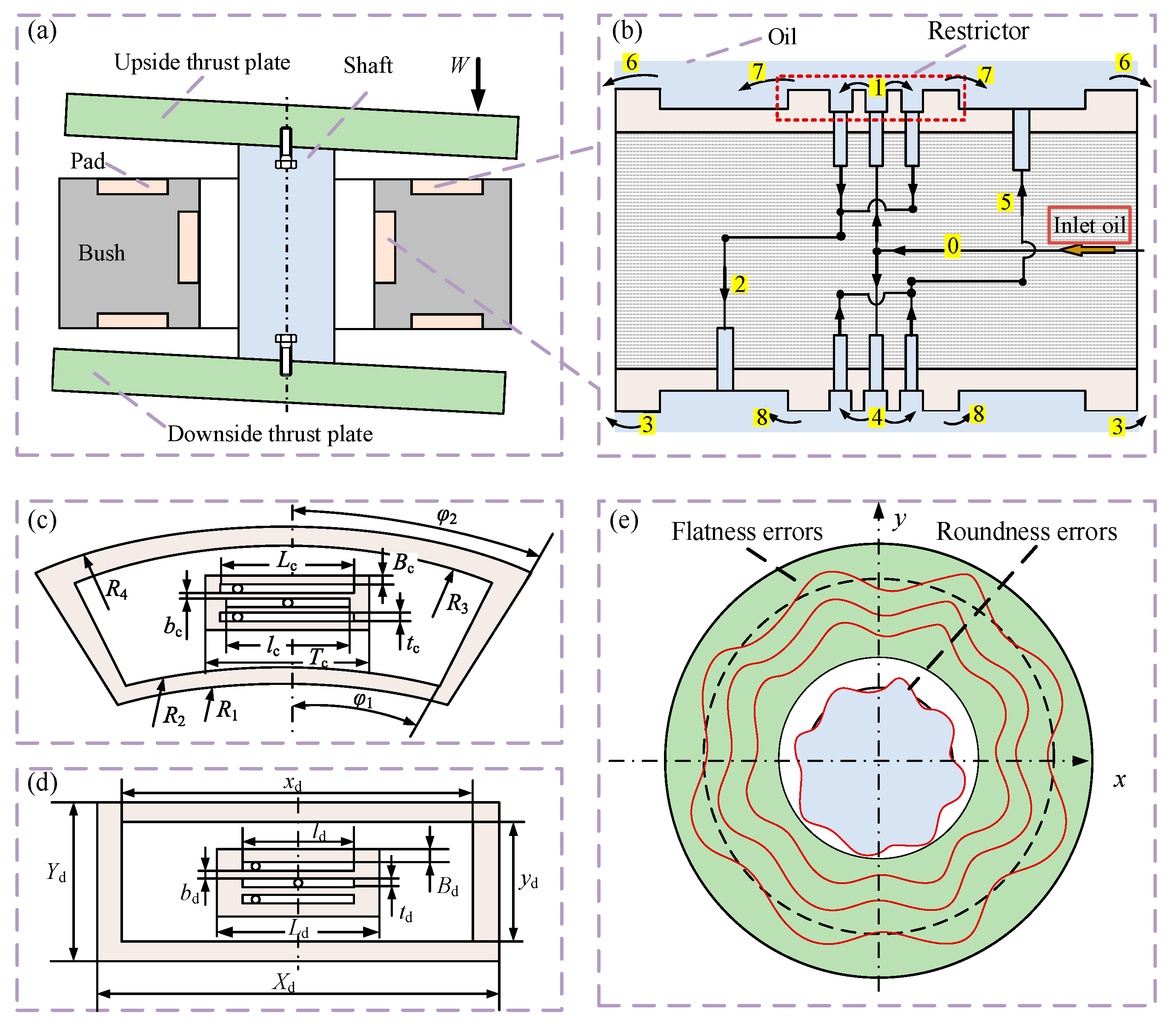
The simplified structure of the hydrostatic turntable with internal feedback is depicted in Figure 1a and comprises a rotating shaft, a bush, and two thrust plates. The shaft and the thrust plates are securely fastened by screws, creating a shaft neck and two thrust bearings. As shown in Figure 1b, the oil enters into the bearing with the pressure of ps to form the internal feedback oil circuit along the directions of arrows 0-1-2-3 and 0-4-5-6, respectively, but in the internal feedback oil circuit, the inward flow effect will be formed between the collector oil recess of the restrictor and the working oil recess (as shown by arrows 7 and 8). It is important to note the substantial distinction between internal feedback bearings and conventional closed bearings, as their operational principles also diverge.
Oil pads for the thrust and journal bearings are illustrated in Figure 1c,d, respectively. Both upside and downside thrust bearings, along with the journal bearing, feature six evenly distributed pads, each separated by exhausted grooves. Geometric errors in the hydrostatic turntable encompass the roundness error of the shaft, as well as the flatness and inclination errors in the upside and downside thrust plates, as demonstrated in Figure 1e. Compared to the geometric errors of the rotating components, the geometric errors of the oil pads can be neglected concerning motion accuracy [14,15].
In the context of thrust bearings, various parameters are defined as follows: R1, R2, R3, and R4 represent the radii of the pads, while φ1 and φ2 denote the angles associated with the pads. The angle of the exhausted groove width is denoted as φC, with bc representing the width of the return oil edge. Additionally, lc stands for the length of the inlet oil groove, tc indicates the width of the inlet oil groove, Tc corresponds to the length of the restrictor, Bc represents the width of the inner flow edge, and Lc signifies the length of the return oil groove.
In the context of journal bearings, various parameters are defined as follows: Rd represents the radius of the journal bearing, while Xd and Yd denote the length and width of the pad, respectively. Additionally, cd stands for the exhausted groove width, xd and yd stand for the length and width of the recess, and Ld corresponds to the length of the restrictor. Other parameters include Bd, representing the width of the inner flow edge, ld indicating the length of the restrictor edge, td signifying the width of the oil inlet groove, and bd representing the width of the restrictor edge.
In the initial state, the thrust bearing supports an eccentric load, prompting concurrent tilt angles and axial displacements in both upside and downside thrust plates. Given the substantially smaller load on the journal bearing compared to the thrust bearing, the inclination of the rotating shaft is disregarded. As the rotating shaft and thrust plate rotate at a speed ω, they initiate departure from the initial position. Owing to the impact of geometric errors, the oil film thickness on the surface of each pad in both the thrust and journal bearings undergoes alterations, leading to a continuous adjustment in the orientation of the rotating components.
In order to better characterize motion errors, a coordinate system O-XYZ is established. The motion accuracy of the rotating component in five degrees of freedom can be represented by decomposing into two radial error motions, X and Y, tilting errors around two axes, and displacement in the Z direction.

2.2. Equivalent Oil Film Clearance

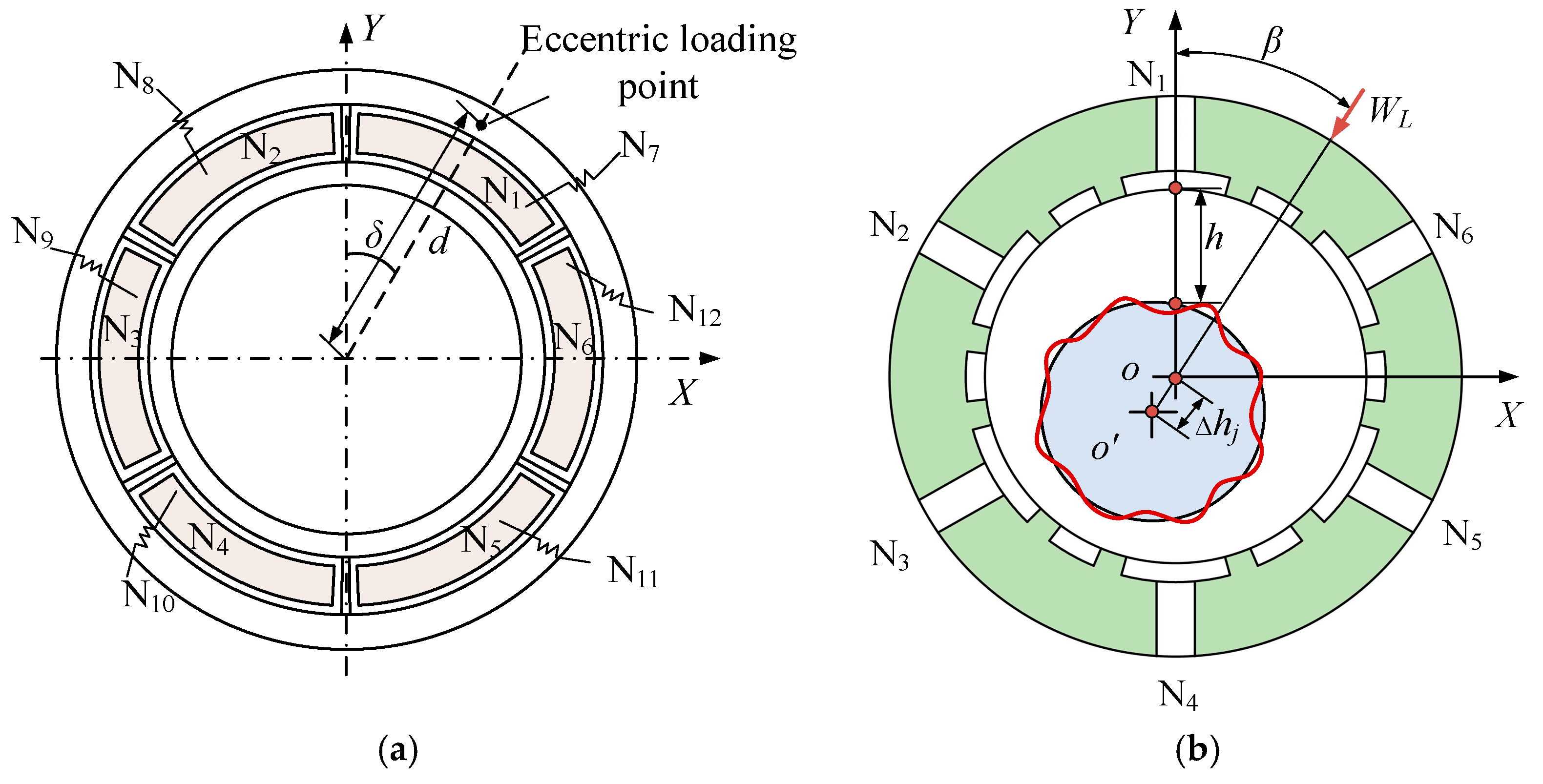
Following the application of an eccentric load and the tilting of the upside thrust plate, illustrated in Figure 2a, the oil film thickness at any given point on the pad of the thrust bearing is:
h t i = h t 0 r cos α tan γ , i = 1 , 2 , , 6
where hti represents the oil film thickness in the upside pad, r denotes the radius of any point on the plate, γ signifies the tilt angle, and α corresponds to the angle between the x-axis and the radius of any point on the plate. N1N12 designates the upside and downside pad numbers, with the subscript i denoting the sequential number.
There is a corresponding relationship between the film thickness of the upside and downside pads after the thrust plate is tilted, as follows:
h t 1 = h t 10 , h t 2 = h t 11 , h t 3 = h t 12 , h t 4 = h t 7 , h t 5 = h t 8 , h t 6 = h t 9
Due to the influence of eccentric load and centrifugal force, the center of the rotating shaft undergoes a shift, no longer aligning with the center of the journal bearing, as depicted in Figure 2b. The oil film thickness, formerly constant at different positions, is now position-dependent. The formula expressing the oil film thickness at any given position is:
h = h j 0 + e cos φ
where e is the eccentricity, equivalent to ∆h, φ is the position angle, and the load application point is connected to the axial line, and rotates counterclockwise.
In accordance with the correspondence of pads, pairs 1–4, 2–5, and 3–6 constitute the internal feedback pads.
The flatness error in the thrust plates and the roundness error in the rotation axis can each be considered as a set of harmonic errors at distinct frequencies, amenable to fitting via Fourier series. Unfolding the contour error of the thrust plate into a Fourier series along the circumference, with radial variation disregarded, reveals that the wavelength increases with radius. The errors in the upside and downside thrust plates are expressible as:
Δ e 1 = E 1 sin n 1 θ ω t + ϕ 10 Δ e 2 = E 2 sin n 2 θ ω t + ϕ 20
where in the context of the upside thrust plate, E1 denotes the error amplitude, n1 is the wave number, and Φ10 is the initial phase angle. The parameters E2, n2, and Φ20 share the same meanings. Additionally, ωt represents the angle of rotation.
Hence, accounting for both tilt error and geometric error, the thicknesses of the upside and downside oil cushion films, denoted as h1i and h2i, can be represented as:
h 1 i = h t i + Δ e 1 , i = 1 , 2 , , 6 h 2 i = h t i + Δ e 2 , i = 7 , 8 , , 12
Similarly, the roundness error of the rotation shaft is expanded into a Fourier series along the circumference, and it can be expressed as follows:
Δ e 3 = E 3 sin n 3 θ ω t + ϕ 30
where E3 represents the error amplitude of the rotation shaft, n3 is the wave number, and Φ30 is the initial phase angle.
The oil film thickness of journal-bearing considering errors can be expressed as:
h j i = h j 0 + Δ e 3 , i = 1 , 2 , 6
The concept of equivalent oil film gap is introduced to characterize the average oil film thickness of the pad considering errors, and its expression is:
h e = S h d x d y S
where S is the area of the pad.

2.3. Motion Error

During turntable rotation, the thrust and journal bearings adhere to the force balance equation, illustrated below:
F Z i = i = 1 6 F t i i = 7 12 F t i W t = 0 F X i = i = 1 6 F j i sin α = 0 F Y i = i = 1 6 F j i cos α = 0
The relationship governing torque balance can be expressed as:
M = M x 2 + M y 2 W z d = 0 M X = i = 1 6 F t i i = 7 12 F t i cos α R 1 + R 4 2 = 0 M Y = i = 1 6 F t i i = 7 12 F t i sin α R 1 + R 4 2 = 0
where Fti represents the thrust bearing oil film load capacity, Fji denotes the journal bearing oil film load capacity, d is the eccentricity, Wt is the total load, Wz is the eccentric load weight, and α equals π/3·(i − 1).
Solving the above equation allows for the determination of motion errors at different rotation angles. Due to the relative independence of the thrust and the journal bearing, the analysis of motion errors will be conducted separately for these two components.

2.3.1. Thrust Bearing

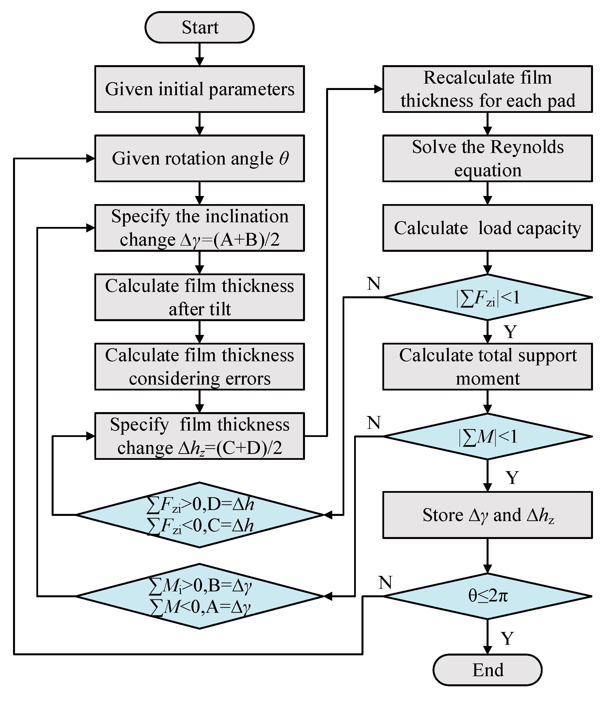
The calculation process for determining the motion error values of the thrust bearing is illustrated in Figure 3. The initial conditions are set, including the dimensions of the thrust bearing structure, load, and rotational speed. The intervals for changes in tilt angle and film thickness are, respectively:
A = 0 B = arctan h t 0 / R 4 C = 0 D = h t 0
Initially, the rotation angle θ of the turntable is specified (θ ∈ [0, 2π]). The tilt angle change ∆γ is set, and the thickness of each oil film is calculated after tilting. Subsequently, geometric errors are incorporated into the film thickness, and an initial thickness change ∆hz is set. The oil film thickness is recalculated, the load capacity is determined based on the current thickness, and finally, convergence checks are performed for supporting force and torque. Convergence values are set to 1, and the process is iterated multiple times until the turntable rotation angle reaches 2π. The calculated ∆γ and ∆hz represent tilt angle error and z-direction displacement error, respectively.

2.3.2. Journal Bearing

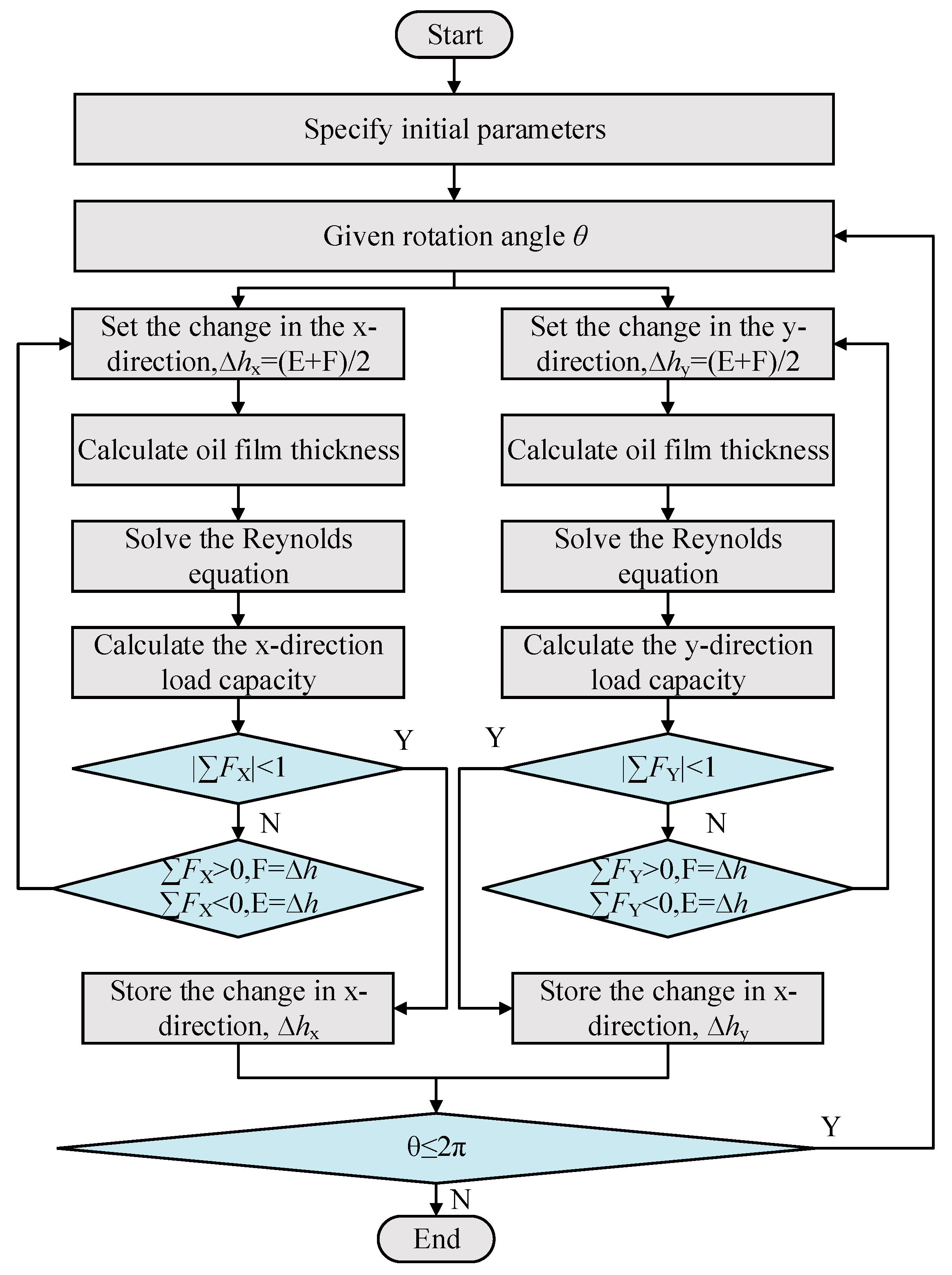
The eccentric load is fixed on the thrust plate and rotates along with it. For the journal bearing, the angle of load action is constantly changing as the thrust plate rotates. Therefore, the components of forces in the x and y directions are continuously changing. The calculation process for determining the motion error values of the journal bearing is illustrated in Figure 4. After specifying the parameters, calculations are performed separately for the x and y-direction force components. The convergence coefficient is set to 1. Within the rotation angle θ of the turntable, the obtained ∆hx and ∆hy represent the variations in x and y-direction displacement motion errors.
The boundary conditions for the journal bearing are satisfied:
E = 0 F = h j 0
where hj0 is the initial film thickness of the journal bearing.
The calculation process for the oil film load capacity of thrust and journal bearings is provided in Appendix A.

3. Result and Discussion

The entire motion process of the hydrostatic turntable is discretized according to angles. Based on the above solution method, multiple motion errors under quasi-static equilibrium can be obtained. The obtained series of discrete points is fitted using Fourier functions. This section aims to analyze the linear and angular deviations of the turntable motion at different stroke positions. Oil pad structural parameters are shown in Table 1.

3.1. The Influence of Error Amplitude on Motion Error

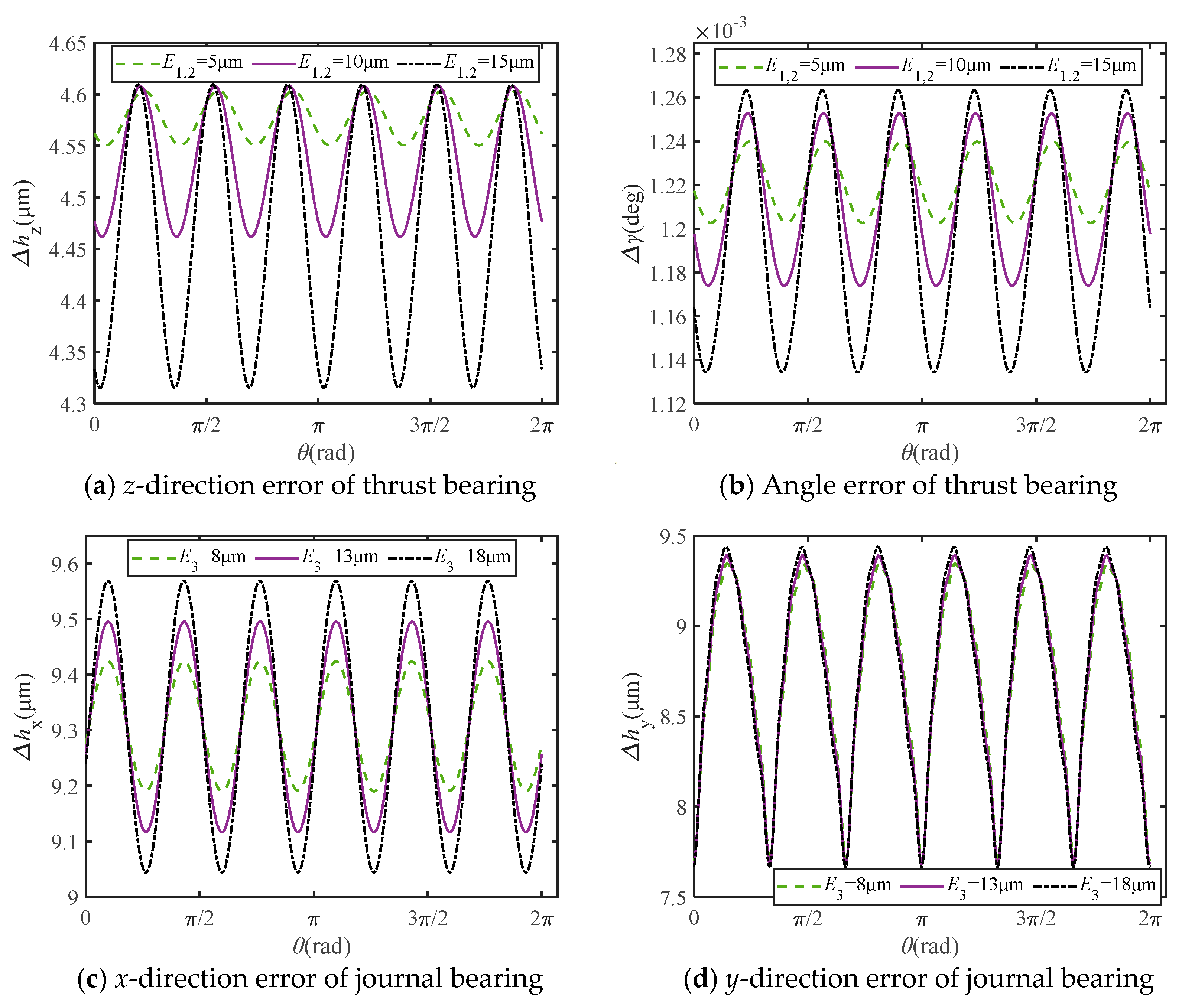
Both thrust and journal bearings will experience displacement when subjected to loads. Therefore, when analyzing the impact of manufacturing errors, the focus should be on comparing the magnitude variation in motion errors, which also reflects the fluctuation of the turntable during motion. Figure 5 shows the influence of contour error magnitude on motion error. In practical applications, the plates and pads are used in pairs. Therefore, in this analysis, a method of controlling a single variable is adopted, where the error functions of the upside and downside plates have the same magnitude, wavelength, and phase. As shown in Figure 5a,b, when the error magnitude of the upside and downside plates is the same, as the error magnitude increases from 5 μm to 15 μm, the maximum linear deviation of the thrust bearing in the z-direction increases by approximately 0.25 μm, and the maximum angular deviation increases by approximately 9.2 × 10⁻⁵°. As shown in Figure 5c,d, the linear deviation of the journal bearing is depicted. With the increase in error magnitude, the maximum deviation in the x-direction increases significantly, while there is little change in the y-direction. This also indicates that the stiffness in the y-direction is better.
In summary, the error equalization effect of the hydrostatic oil film results in its motion error being much smaller than the manufacturing error. The motion error of bearings is positively correlated with the magnitude of the error. However, the linear deviation of the journal bearing in the y-direction is less sensitive to error magnitude. In practical engineering, efforts should be made to reduce the error magnitude of the thrust plate if possible.

3.2. The Influence of Wave Number on Motion Error

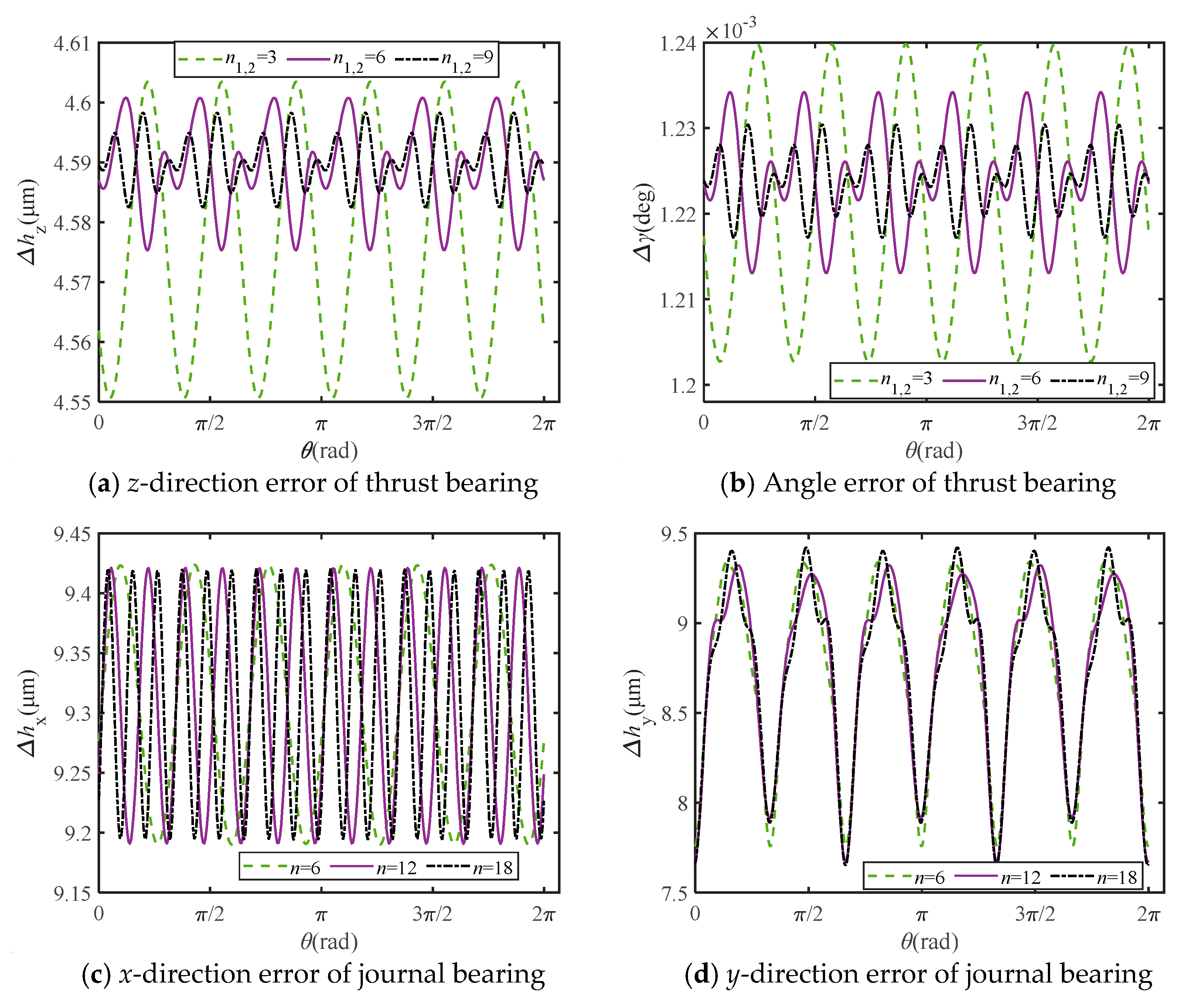
As shown in Figure 6, the influence of wave number on motion error is depicted. From Figure 6a,b, it can be observed that as the wave number increases, both linear error and angular error in the z-direction significantly decrease. This is because the increase in wave number leads to a reduction in the difference in oil film thickness at various points. When the wave number increases from 3 to 6, the motion error is significantly reduced by approximately 51%, indicating that increasing the wave number of the flatness error effectively improves the motion accuracy of the thrust bearing. From Figure 6c, it can be observed that the number of peaks and valleys in the error curve in the x-direction is the same as the wave number, while the variation in wave number has no effect on the overall deviation magnitude. As depicted in Figure 6d, the rise in wave number exerts a negligible impact on the error in the y-direction.

3.3. The Influence of Initial Phase Angle on Motion Error

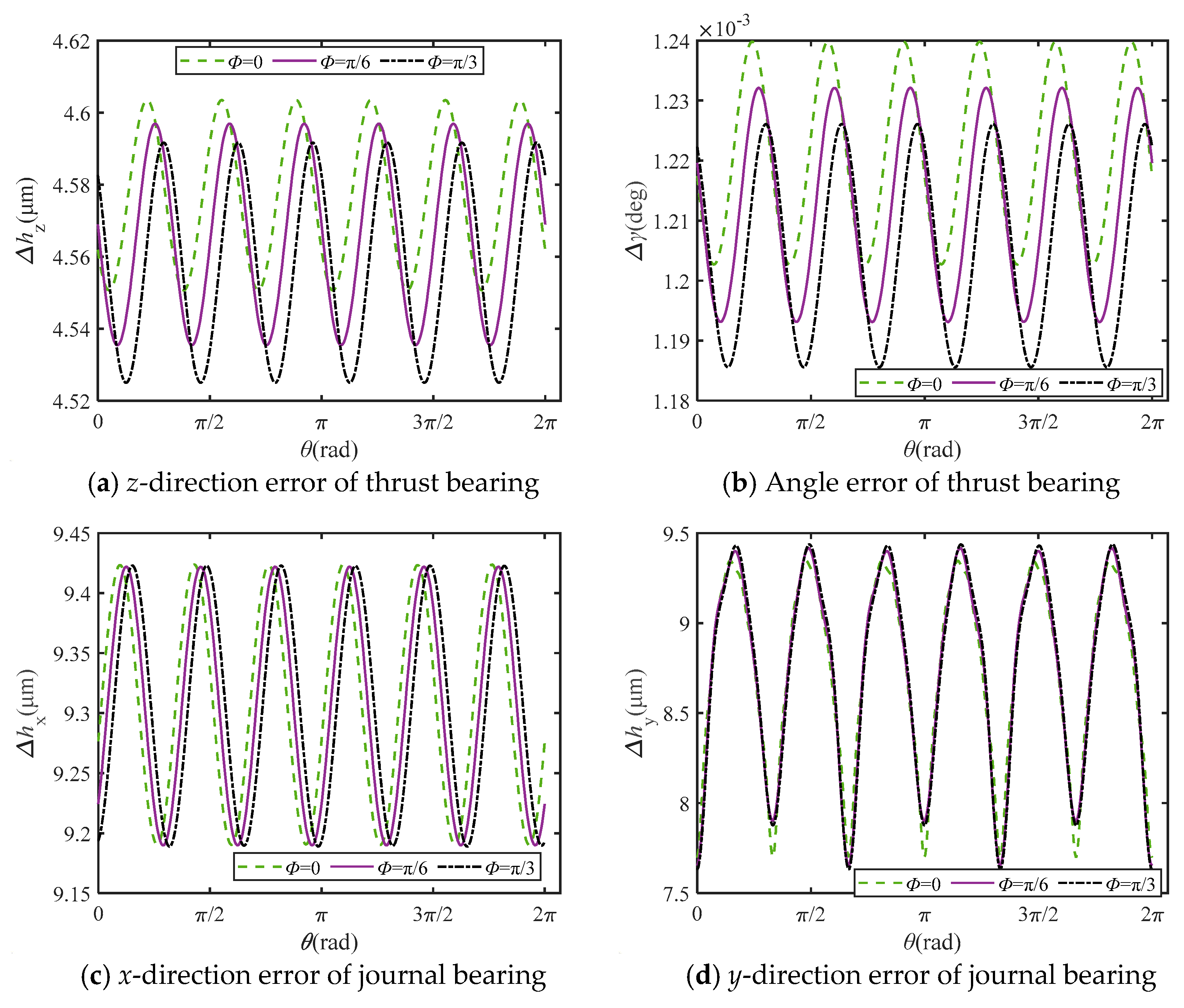
Figure 7 illustrates the impact of phase difference on motion error. For the thrust bearing, increasing the phase angle results in a downward shift in the overall linear deviation and angular error curves in the z-direction, with no change in magnitude. When φ = 0 , the axial motion error Δ z varies from 4.55 μm to 4.60 μm, with a peak-to-peak value of only 0.05 μm. This suggests that increasing the phase angle can decrease film thickness variation under identical load conditions. As for the journal bearing, an increase in phase angle leads to a global shift in the error curve in the x-direction, while peak and valley values remain unchanged, maintaining consistent fluctuation magnitude. There is negligible alteration in the error in the y-direction.

3.4. The Influence of Internal Flow Effect on Motion Accuracy

The internal feedback hydrostatic turntable restrictor is installed in the recess, allowing oil to flow not only to the opposite recess but also to the same-side recess. Due to the numerous size parameters of the restrictor, for ease of analysis, the flow coefficient is adopted to reflect the restriction effect of the restrictor:
ξ = R c i R t i , i = 1 , 2
where Rc represents the restrictor fluid resistance, and Rt represents the internal flow resistance. The specific expressions are detailed in the appendix.
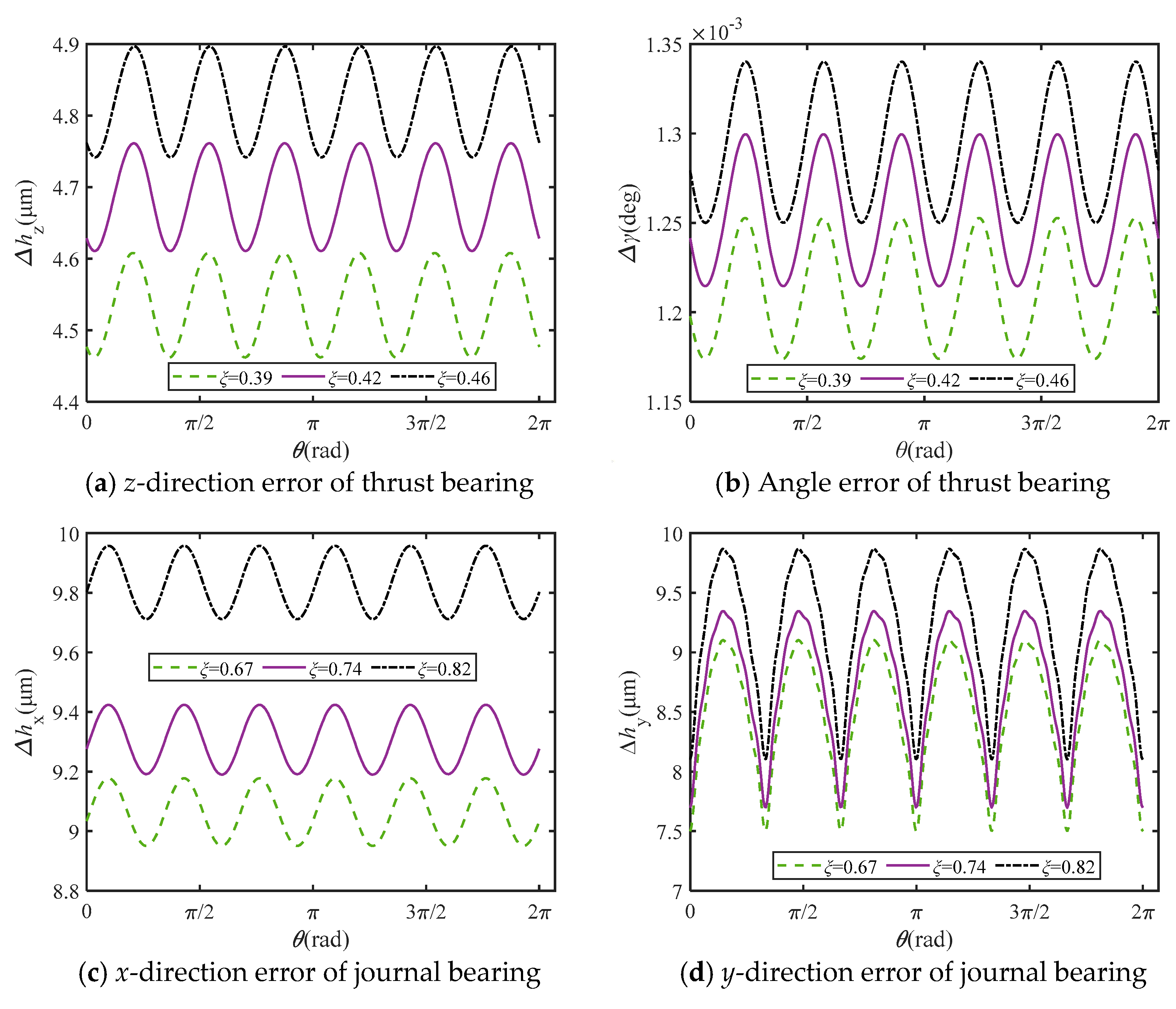
It is important to emphasize here that by adjusting the dimensions of individual restrictors, changes in the flow coefficient can be achieved without discussing each parameter. As shown in Figure 8, with the decrease in the flow coefficient, the linear deviation and angular error of the thrust bearing in the z-direction decreases, but the overall magnitude remains unchanged. For journal bearings, an increase in the flow coefficient results in an increase in linear deviation in the x and y directions, but the overall magnitude remains unchanged. In conclusion, for the design of restrictors, it is possible to better enhance the stiffness of the turntable and improve dynamic performance. For turntable motion accuracy, controlling the form errors of components should still be prioritized.

4. Experiments

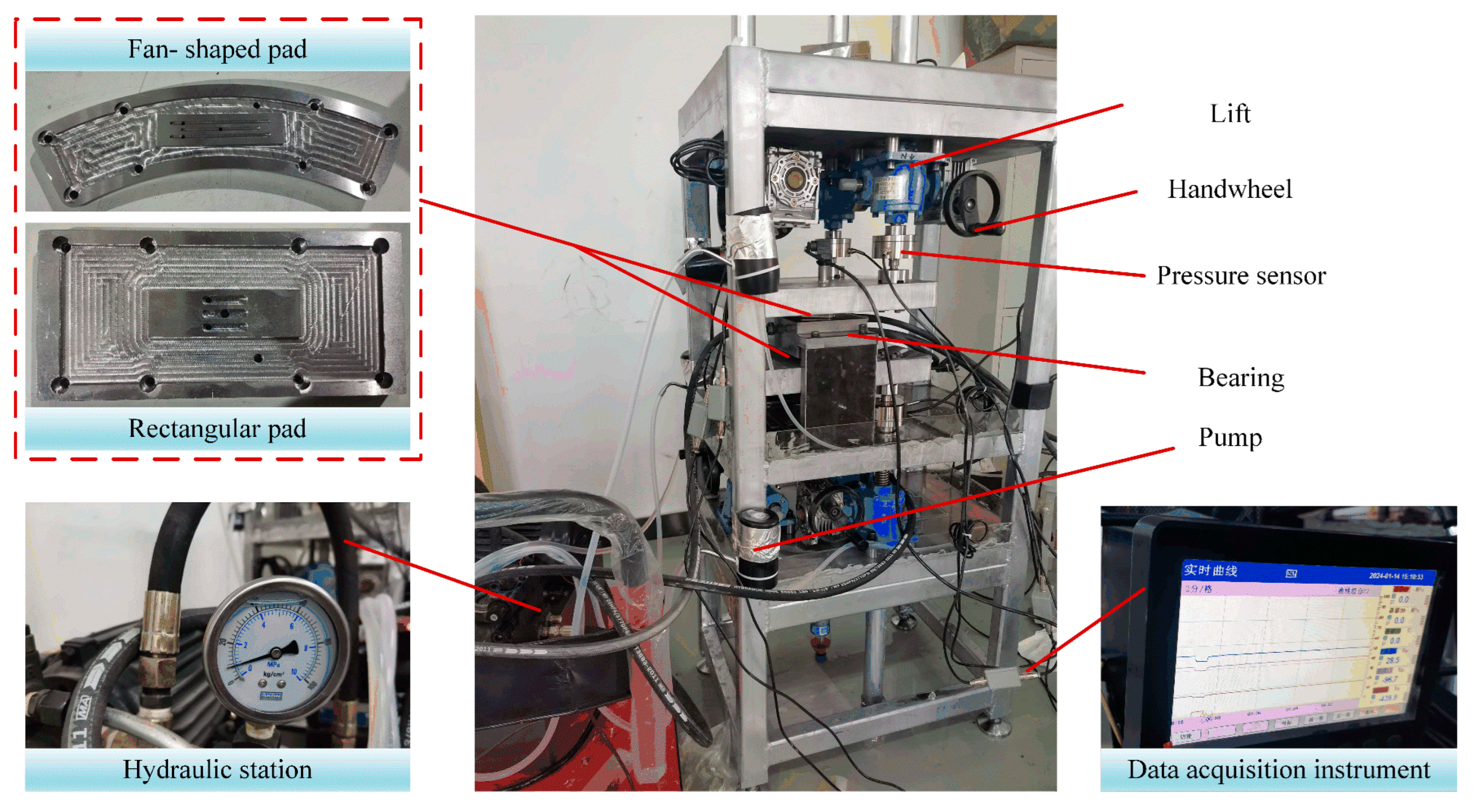
From the above analysis, it can be concluded that the key to calculating motion errors lies in correctly solving the load capacity. In order to further validate the proposed method for calculating the oil film load capacity in this paper, an internal feedback oil pad load capacity testing device, as shown in Figure 9, is established and subjected to experimental testing. The device consists of a supply system, data acquisition system, and support system. The supply system consists of a hydraulic station, oil pump, and oil pipes, while the data acquisition system comprises six sets of pressure sensors, amplifiers, and data acquisition instruments. The pressure sensor utilized in this study has a specified overall accuracy of ±0.3% of the full scale (FS), which encompasses the combined effects of nonlinearity, hysteresis, and non-repeatability, under standard laboratory conditions (25 ± 2 °C). The relative uncertainty of the load measurement can be expressed as:
U F = Δ F F × 100 %
where U F is the relative measurement uncertainty, Δ F is the maximum allowable measurement error of the load sensor, and F is the measured load.
The corresponding relative uncertainty is approximately ±0.5% at full scale. Therefore, the uncertainty of the load measurement in this experiment is within ±0.5%.
In addition, each measurement is repeated three times, and the average value was adopted as the final experimental result to reduce the influence of random errors.
The support system includes an internal feedback oil pad, support plate, and lifting mechanism. The upside and downside bearing are both fixed with internal feedback oil pads, and force sensors are installed on the support plate. The relative position between the handwheel and the oil pad is adjusted to simulate the oil film thickness. Finally, a feeler gauge is used for calibrating the oil film clearance. After stabilizing the oil supply, the digital data acquisition instrument displays the difference in total external force between the upside and downside support plates.
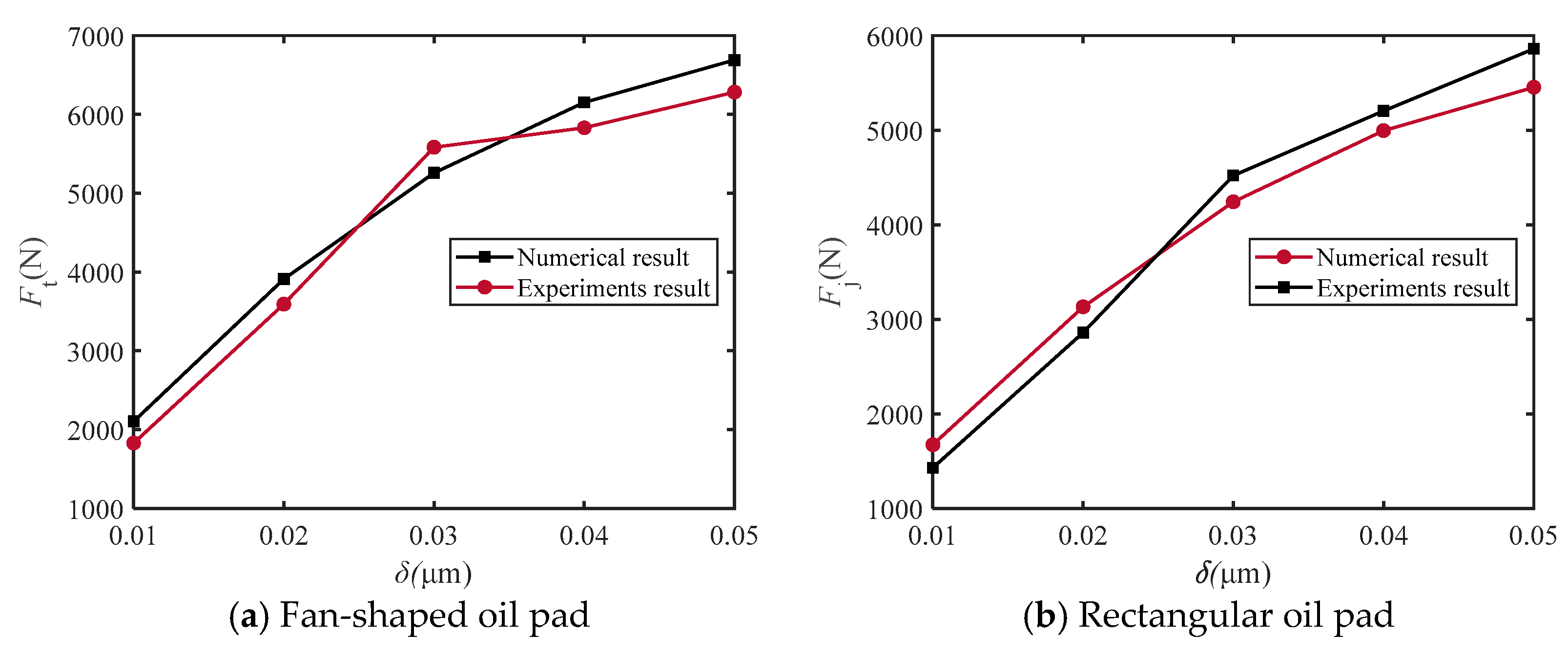
The initial film thickness of the upside and downside pads is 0.10 mm, and the thickness change per iteration is 0.01 mm. The oil pump supplies oil pressure at 1 MPa. After multiple adjustments, load tests were conducted separately on two types of internal feedback oil pads: fan-shaped and rectangular. The comparison between experimental and theoretical results is shown in Figure 10, where it can be observed that the theoretical calculation of load capacity is relatively close to the experimental results. The maximum relative errors are 15.03% and 17.13%, while the average relative errors are 8.35% and 8.74% for the fan-shaped and rectangular oil pads, respectively. These results verify the accuracy of the proposed hydraulic model and provide a reliable foundation for subsequent motion error prediction.

5. Conclusions

This paper proposes a method for analyzing motion errors of a hydrostatic turntable under biased loading conditions. The motion precisions of thrust and journal bearings are mutually independent, providing a convenient approach for predicting motion errors of hydrostatic turntable. The following conclusions can be drawn from simulation and experimental results:
(1)
The motion errors of thrust and journal bearings exhibit a positive correlation with the magnitude of mating surface errors. Specifically, when the mating surface error amplitude increased from 5 μm to 15 μm, the motion errors of thrust bearings increased by approximately 0.25 μm. However, for journal bearings, the sensitivity of motion errors in the y-direction is relatively smaller.
(2)
The larger the wave number of the flatness error of the thrust plate, the smaller the linear deviation and angular deviation of the thrust bearing, indicating that smoother mating surfaces are advantageous for reducing motion errors. However, for journal bearings, influenced by eccentric loads, increasing the wave number of the roundness error of the rotating shaft does not significantly reduce motion errors.
(3)
Changing the phase angle does not reduce the motion errors of thrust bearings and journal bearings. Despite the reduction in the throttle coefficient, which may not decrease the magnitude of motion errors, it can enhance the rigidity of the turntable.
(4)
The future work will focus on the direct experimental measurement and validation of five-degree-of-freedom motion errors of a complete hydrostatic turntable under eccentric loading conditions, as well as further investigation of the effects of load parameters and structural optimization.

Author Contributions

Conceptualization, H.M.; methodology, H.M.; software, H.M.; validation, H.M., Q.S. and X.D.; formal analysis, Q.C.; investigation, H.M.; resources, H.M.; data curation, H.M.; writing—original draft preparation, H.M.; writing—review and editing, H.M., Q.S., X.D. and Q.C.; visualization, H.M. and M.Z.; supervision, Q.C. and M.Z.; project administration, H.M. and M.Z.; funding acquisition, H.M. All authors have read and agreed to the published version of the manuscript.

Funding

This research was funded by Natural Science Foundation of Zhejiang Province grant number LQN26E050053.

Data Availability Statement

The original contributions presented in this study are included in the article.

Conflicts of Interest

Author M.Z. was employed by the company Genertec Machine Tool Engineering Research Institute Co., Ltd. The remaining authors declare that the research was conducted in the absence of any commercial or financial relationships that could be construed as a potential conflict of interest.

Appendix A

The following equations are used to calculate the load capacity of the oil pad, mainly including the Reynolds equation, the oil passage equivalent equation, the fluid continuity equation, and the load capacity equation.
  • Reynolds Equation
The oil pad pressure pti of the hydrostatic thrust bearing satisfies the Reynolds equation (where i is the index):
r r h t i 3 η p t i r + φ h t i 3 η p t i r φ = 6 r r U t i h t i + 6 φ V t i h t i + r ρ V t i 2 h t i 3 η
where r and φ represent the radial and circumferential angular variables, respectively. hti is the film thickness, pti is the recess pressure, η is viscosity, ρ is oil density, Uti is radial velocity, and Vti is circumferential velocity.
The oil pad pressure pji of the journal bearing can be described by the Reynolds equation as follows:
x h j i 3 η p j i x + y h j i 3 η p j i y = 6 x U j i h j i + 6 y V j i h j i
where hji is film thickness, pji is the recess pressure, Uji is x-direction velocity, and Vji is y-direction velocity.
The Reynolds equation was solved using a finite difference method. The nondimensionalization and normalization procedures were performed according to the established formulations reported in previous studies [20]. The convergence of the iterative calculation was evaluated based on the normalized residual: R = p k + 1 p k p k + 1 . The iteration is terminated when R < 1 × 10 7 . To verify the grid independence, calculations were performed using grids of 100 × 100 and 150 × 150. The difference in the predicted load-carrying capacity between the two grids was less than 2%, demonstrating that the selected grid density provides sufficient accuracy.
  • Oil circuit equivalent equation
Solving the liquid resistance of the oil passage is crucial for pressure solution. According to reference [27,28], the oil circuit of the internal feedback oil pad can be simplified into a star-shaped oil passage, and the expression for total liquid resistance is given by:
R z = R k 1 + R k 2 R k 3 + R k 4 R k 1 + R k 2 + R k 3 + R k 4 + R k 3 R k 1 = R a R o 2 R a + R o 1 + R o 2 , R k 2 = R a R o 1 R a + R o 1 + R o 2 , R k 3 = R o 1 R o 2 R a + R o 1 + R o 2
The pressure in the upside and downside recess is:
p 1 = p s p s R z R c 1 + R k 1 R c 1 + R k 1 + R c 2 + R k 2 R c 2 p 2 = p s p s R z R c 2 + R k 2 R c 1 + R k 1 + R c 2 + R k 2 R c 1
The expressions for each liquid resistance are:
R c 1 = 12 η 0 b c l c + L c h 0 Δ h 3 , R c 2 = 12 η 0 b c l c + L c h 0 + Δ h 3 R t 1 = 12 η 0 B c L c + T c h 0 Δ h 3 , R t 2 = 12 η 0 B c L c + T c h 0 + Δ h 3 R o 1 = 6 η 0 h 0 Δ h B b l + L l b , R o 2 = 6 η 0 h 0 + Δ h B b l + L l b
where L = ( R 4 + R 1 ) / 2 φ 1 , B = R 4 R 1 , l = ( R 3 + R 2 ) / 2 φ 2 , b = R 3 R 2
  • Flow Continuity Equation
The flow rates Qti and Qji of each individual thrust and journal pad are denoted as:
Q t i = S 1 h t i 12 η p t i φ U t i h t i 2 d r + S 2 h t i 12 η p t i r d φ + S 3 h t i 12 η p t i φ + U t i h t i 2 d r + S 4 h t i 12 η p t i r d φ + p 1 R t 1 + R o 1 Q j i = S 1 h j i 12 η p j i x U j i h j i 2 d r + S 2 h j i 12 η p j i y d c + S 3 h j i 12 η p j i x + U j i h i 2 d r + S 4 h j i 12 η p i y d x + p 2 R t 2 + R o 2
  • Load capacity equation
The load capacities Fti and Fji for a single thrust and journal pad, respectively, are expressed as follows:
F t i = P a d p t i r d r d φ F j i = P a d p j i cos x / R d d x d y

References

  1. Zha, J.; Lv, D.; Jia, Q.; Chen, Y. Motion straightness of hydrostatic guideways considering the ratio of pad center spacing to guide rail profile error wavelength. Int. J. Adv. Manuf. Technol. 2016, 82, 2065–2073. [Google Scholar] [CrossRef] [Scilit]
  2. Wang, Y.; Liu, Z.; Zhao, Y.; Cheng, Q.; Cai, L. Research on an ANN system for monitoring hydrostatic turntable performance based on ODNE training. Tribol. Int. 2019, 133, 21–31. [Google Scholar] [CrossRef] [Scilit]
  3. Du, J.; Liang, G. Performance comparative analysis of hydrostatic bearings lubricated with low-viscosity cryogenic fluids. Tribol. Int. 2019, 137, 139–151. [Google Scholar] [CrossRef] [Scilit]
  4. Wu, Y.; Qiao, Z.; Ge, H.; Xue, J.; Wang, B. Application of direct coupling method to design problems of hydrostatic guideways accounting for fluid-structure interactions. Adv. Eng. Softw. 2023, 177, 103410. [Google Scholar] [CrossRef] [Scilit]
  5. Zhang, P.; Chen, Y.; Zha, J.; Lei, Z. Prediction of motion accuracy in five degrees of freedom for hydrostatic rotary table with any recess number. Proc. Inst. Mech. Eng. Part C J. Mech. Eng. Sci. 2021, 235, 3389–3406. [Google Scholar] [CrossRef] [Scilit]
  6. Zha, J.; Chen, Y.; Zhang, P. Precision design of hydrostatic thrust bearing in rotary table and spindle. Proc. Inst. Mech. Eng. Part B J. Eng. Manuf. 2018, 232, 2044–2053. [Google Scholar] [CrossRef] [Scilit]
  7. Zha, J.; Chen, Y.; Zhang, P.; Chen, R. Effect of design parameters and operational conditions on the motion accuracy of hydrostatic thrust bearing. Proc. Inst. Mech. Eng. Part C J. Mech. Eng. Sci. 2020, 234, 1481–1491. [Google Scholar] [CrossRef] [Scilit]
  8. Zhang, P.; Chen, Y.; Liu, X. Relationship between roundness errors of shaft and radial error motions of hydrostatic journal bearings under quasi-static condition. Precis. Eng. 2018, 51, 564–576. [Google Scholar] [CrossRef] [Scilit]
  9. Zhang, P.; Chen, Y.; Zhang, C.; Zha, J.; Wang, T. Influence of geometric errors of guide rails and table on motion errors of hydrostatic guideways under quasi-static condition. Int. J. Mach. Tools Manuf. 2018, 125, 55–67. [Google Scholar] [CrossRef] [Scilit]
  10. Zhang, P.; Chen, Y.; Zha, J. Relationship between geometric errors of thrust plates and error motions of hydrostatic thrust bearings under quasi-static condition. Precis. Eng. 2017, 50, 119–131. [Google Scholar] [CrossRef] [Scilit]
  11. Zhang, P.; Peng, Y. Influence of rotation speed on motion accuracy of hydrostatic journal bearing. Nonlinear Dyn. 2021, 105, 295. [Google Scholar] [CrossRef] [Scilit]
  12. Zhao, Y.; Wu, H.; Yang, C.; Cai, L.; Liu, Z. Effect of guide rail profile errors on the motion accuracy for a heavy-duty hydrostatic turntable. Proc. Inst. Mech. Eng. Part C J. Mech. Eng. Sci. 2019, 233, 5350–5362. [Google Scholar] [CrossRef] [Scilit]
  13. Wang, Z.; Zhao, W.; Chen, Y.; Lu, B. Prediction of the effect of speed on motion errors in hydrostatic guideways. Int. J. Mach. Tools Manuf. 2013, 64, 78–84. [Google Scholar] [CrossRef] [Scilit]
  14. Qi, E.; Fang, Z.; Sun, T.; Chen, J.; Liu, C.; Wang, J. A method for predicting hydrostatic guide error averaging effects based on three-dimensional profile error. Tribol. Int. 2016, 95, 279–289. [Google Scholar] [CrossRef] [Scilit]
  15. Zha, J.; Xue, F.; Chen, Y. Straightness error modeling and compensation for gantry type open hydrostatic guideways in grinding machine. Int. J. Mach. Tools Manuf. 2017, 112, 1–6. [Google Scholar] [CrossRef] [Scilit]
  16. Zha, J.; Wang, Z.; Xue, F.; Chen, Y. Effect of working position on vertical motion straightness of open hydrostatic guideways in grinding machine. Chin. J. Mech. Eng. 2017, 30, 46–52. [Google Scholar] [CrossRef] [Scilit]
  17. Niu, P.; Cheng, Q.; Zhang, T.; Yang, C.; Zhang, Z.; Liu, Z. Hyperstatic mechanics analysis of guideway assembly and motion errors prediction method under thread friction coefficient uncertainties. Tribol. Int. 2023, 180, 108275. [Google Scholar] [CrossRef] [Scilit]
  18. Michalec, M.; Polnický, V.; Foltýn, J.; Svoboda, P.; Šperka, P.; Hurník, J. The prediction of large-scale hydrostatic bearing pad misalignment error and its compensation using compliant support. Precis. Eng. 2022, 75, 67–79. [Google Scholar] [CrossRef] [Scilit]
  19. Shi, C.; Wang, Z.; Peng, Y.; Lei, P.; Li, C. Quasi-static kinematics model for motion errors of closed hydrostatic guideways in ultra-precision machining. Precis. Eng. 2021, 71, 90–102. [Google Scholar] [CrossRef] [Scilit]
  20. Liu, Z.; Zhan, C.; Cheng, Q.; Zhao, Y.-S.; Li, X.-Y.; Wang, Y.-D. Thermal and tilt effects on bearing characteristics of hydrostatic oil pad in rotary table. J. Hydrodyn. 2016, 28, 585–595. [Google Scholar] [CrossRef] [Scilit]
  21. Zhang, Y.; Lu, C.; Zhao, H.; Shi, W.; Liang, P. Error averaging effect of hydrostatic journal bearings considering the influences of shaft rotating speed and external load. IEEE Access 2019, 7, 106346–106358. [Google Scholar] [CrossRef] [Scilit]
  22. Xu, C.; Chen, S.; Lu, C.; Wang, K.; Sun, J. Direct compensation of the spindle rotation error with an active hydrostatic journal bearing system. Proc. Inst. Mech. Eng. Part C J. Mech. Eng. Sci. 2022, 236, 2340–2351. [Google Scholar] [CrossRef] [Scilit]
  23. Fang, C.; Huo, D.; Huang, X. A comprehensive analysis of factors affecting the accuracy of the precision hydrostatic spindle with mid-thrust bearing layout. Int. J. Adv. Manuf. Technol. 2021, 114, 949–967. [Google Scholar] [CrossRef] [Scilit]
  24. Cheng, Q.; Ren, W.; Liu, Z.; Chen, D.-J.; Gu, P.-H. Load-induced error identification of hydrostatic turntable and its influence on machining accuracy. J. Cent. South Univ. 2016, 23, 2558–2569. [Google Scholar] [CrossRef] [Scilit]
  25. Ma, H.; Zhang, T.; Yang, C.; Liu, Z.; Zhao, Y. Research on the supporting mechanism of internal feedback hydrostatic hybrid bearing considering flow rate correction. Proc. Inst. Mech. Eng. Part J J. Eng. Tribol. 2024, 238, 1593–1609. [Google Scholar] [CrossRef] [Scilit]
  26. Ma, H.; Liu, Z.; Yang, C.; Cheng, Q.; Zhao, Y. Research on the support performance of internal feedback hydrostatic thrust and journal bearing considering load effect. Mathematics 2024, 12, 1367. [Google Scholar] [CrossRef] [Scilit]
  27. Yang, C.; Shao, S.; Li, Y.; Liu, Z.; Zhao, Y.; Ma, H. Performance Analysis and Restrictor Structure Improvement of an Internal Feedback Hydrostatic Turntable Oil Pad Considering Internal Flow. Adv. Theory Simul. 2024, 7, 2300822. [Google Scholar] [CrossRef] [Scilit]
  28. Yang, C.; Shao, S.; Cheng, Y.; Liu, Z.; Zhao, Y. Analysis and Optimization of an Internal Feedback Hydrostatic Turntable Oil Pad Power Consumption Based on Finite Difference Method. Int. J. Precis. Eng. Manuf. 2023, 24, 2211–2228. [Google Scholar] [CrossRef] [Scilit]
Figure 1. Structures of the thrust bearing and shaft roundness errors. (a) Structure of internal feedback static pressure turntable. (b) Oil circuit. (c) Thrust pad. (d) Journal pad. (e) Shaft roundness errors and flatness errors.
Lubricants 14 00323 g001
Figure 2. Calculation model for equivalent film thickness. (a) Thrust bearing. (b) Journal bearing.
Lubricants 14 00323 g002
Figure 3. Computational procedure of thrust-bearing motion errors.
Lubricants 14 00323 g003
Figure 4. Computational procedure of journal-bearing motion errors.
Lubricants 14 00323 g004
Figure 5. The influence of error amplitude on motion error. (n1,2 = 3, n3 = 6, Φ10,20,30 = 0).
Lubricants 14 00323 g005
Figure 6. The influence of wave number on motion error. (E1,2 = 5 μm, E3 = 8 μm, Φ10,20,30 = 0).
Lubricants 14 00323 g006
Figure 7. The influence of initial phase angle on motion accuracy. (E1,2 = 5 μm, E3 = 8 μm, n1,2 = 3, n3 = 6).
Lubricants 14 00323 g007
Figure 8. The influence of internal flow effect on motion error. (E1,2 = 5 μm, E3 = 8 μm, n1,2 = 3, n3 = 6, Φ10,20,30 = 0).
Lubricants 14 00323 g008
Figure 9. Measurement device of load capacity.
Lubricants 14 00323 g009
Figure 10. Verification of oil pad load capacity.
Lubricants 14 00323 g010
Table 1. Structural parameters of the pad.
ParameterValueParameterValue
R1/mm239R2/mm249
R3/mm298R4/mm308
φ228.9φ126.9
bc/mm2lc/mm63.26
tc/mm3Tc/mm85
Bc/mm6Lc/mm70
Xd/mm164.37Yd/mm110
xd/mm144.51yd/mm90
Ld/mm60ld/mm60
bd/mm2td/mm6
Bd/mm4Rd/mm180
cd/mm24.13φc2.2
ω/r·min−160η0/Pa·s0.0085
ps/Pa1.5 × 106ρ/kg·m3850
Disclaimer/Publisher’s Note: The statements, opinions and data contained in all publications are solely those of the individual author(s) and contributor(s) and not of MDPI and/or the editor(s). MDPI and/or the editor(s) disclaim responsibility for any injury to people or property resulting from any ideas, methods, instructions or products referred to in the content.