1. Introduction
Friction and wear remain fundamental aspects of mechanical systems, governing energy dissipation, material degradation, and device lifetime [
1] across length scales from macroscopic machinery to micro– and nanoelectromechanical systems [
2]. The discovery of structural superlubricity, a regime of ultralow friction arising from lattice incommensurability, has opened a conceptually new route to frictionless motion without lubricants [
3,
4,
5]. Layered materials, particularly graphite, are ideal systems for realizing structural superlubricity due to their atomically flat basal planes and weak interlayer van der Waals interactions [
6,
7,
8]. Superlubricity has been experimentally observed in graphite at scales ranging from nanoscale atomic force microscopy to microscale [
5,
9,
10] and even macroscale graphite mesas [
11], with measured friction coefficients reaching ultralow values that approach the detection limits of current experimental techniques [
12,
13].
Recent studies have highlighted the important role of contact edges in the frictional behaviour of superlubric interfaces. The edges have unsaturated bonds, localized electronic states, and enhanced chemical interactions, which promote pinning and local coherence [
14,
15,
16,
17], thereby increasing friction. Related theoretical and simulation studies [
18,
19,
20] have further predicted that edges and defects can induce the formation of localized pinning sites, trigger stick–slip dynamics, and contribute to frictional dissipation in superlubric systems. Hu et al. [
21] showed that by decoupling edge and in–plane friction contributions, edge–edge and edge–surface contacts play a dominant role in dissipation compared with basal–plane contact. Despite these advances, precise control over edge–contact configurations remain limited, and friction modulation through edge design in structurally superlubric interfaces has yet to be achieved. Geometric boundary engineering should be distinguished from conventional contact–area effects, as these two quantities capture fundamentally different aspects of the interfacial interaction [
22]. Previous studies have established that twist–angle engineering and grain boundary dislocations undergoing shear–induced buckling transitions are effective strategies for modulating superlubricity, driving nonmonotonic friction behavior and energy dissipation through hysteretic elastic storage [
3,
8,
23,
24].
This study proposes a controllable method for fabricating patterned edge structures with well–defined sizes and geometries while preserving the atomic–level surface smoothness. Based on this design, we establish an edge–contact architecture that directly reveals edge effects in a structurally superlubric system, demonstrating that hole perimeter is a key geometric parameter governing frictional behaviour and providing an edge–based route for tuning friction in structurally superlubric graphite/graphite interfaces.
2. Materials and Methods
2.1. Methods
Silicon (Si) wafers were diced into approximately 1 cm × 1 cm pieces and ultrasonically cleaned in acetone and isopropanol (IPA) for 20 min each, then dried under nitrogen. Graphite flakes were then transferred onto Si substrates via mechanical exfoliation using Scotch tape, yielding atomically smooth graphite surfaces. Micro–hole arrays were fabricated on the graphite surface using photolithography and etching. Triangular, circular, and square holes with characteristic sizes ranging from 2 to 6 µm were fabricated. These holes introduce well–defined graphite edges. To reduce contamination from fabrication residues, the patterned samples were repeatedly exfoliated with Scotch tape before transferring the graphite mesa for measurement. This process effectively removes photoresist residues and exposes clean, atomically smooth graphite surfaces with holes, which are essential for achieving structural superlubricity [
25].
Microscale graphite mesas for sliding experiments were prepared from thin graphite flakes.
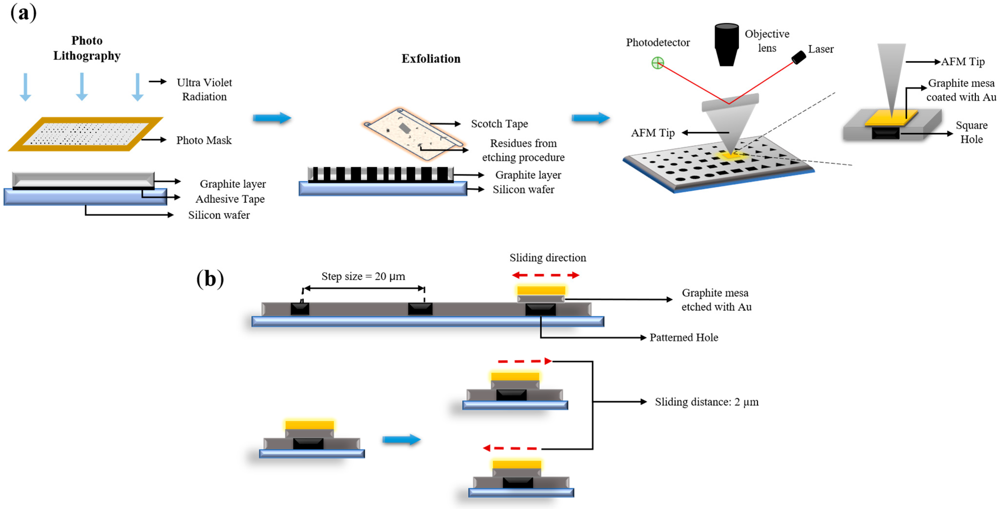
Figure 1a shows that the flakes were first transferred onto a flat graphite surface using a thermal release tape at 150° C, and then patterned into 8 µm × 8 µm graphite mesas via photolithography. The graphite mesas were subsequently positioned onto the patterned substrates using a transfer system with a tungsten probe [
26]. All lateral force measurements were conducted by reciprocating the graphite mesa along the ±x—direction with the scan centered on a single patterned hole as shown in
Figure 1b. The displacement range was selected such that the hole remained enclosed within the mesa contact area throughout the entire sliding cycle, ensuring that the measured lateral force reflected the frictional response of a single isolated hole. Hole–to–hole spacing was fixed at 20 μm to prevent interactions with neighbouring features.
The total contact edge comprises two components: the graphite mesa edge length and the hole edge length. The friction contribution from the hole edges may substantially exceed that of the mesa edges. This difference is attributed to the non–vertical sidewall profiles of the microfabricated holes, which may engage the sliding mesa across multiple edge levels simultaneously, generating a higher density of localized pinning sites and greater cumulative dissipation.
The subsequent discussion, therefore, focuses on the hole edge contribution as the dominant parameter governing interfacial friction enhancement. The size of the graphite mesa is fixed during the measurement, and the contact edge length is systematically tuned by varying the size and hole geometry.
2.2. Morphological and Topographical Characterization
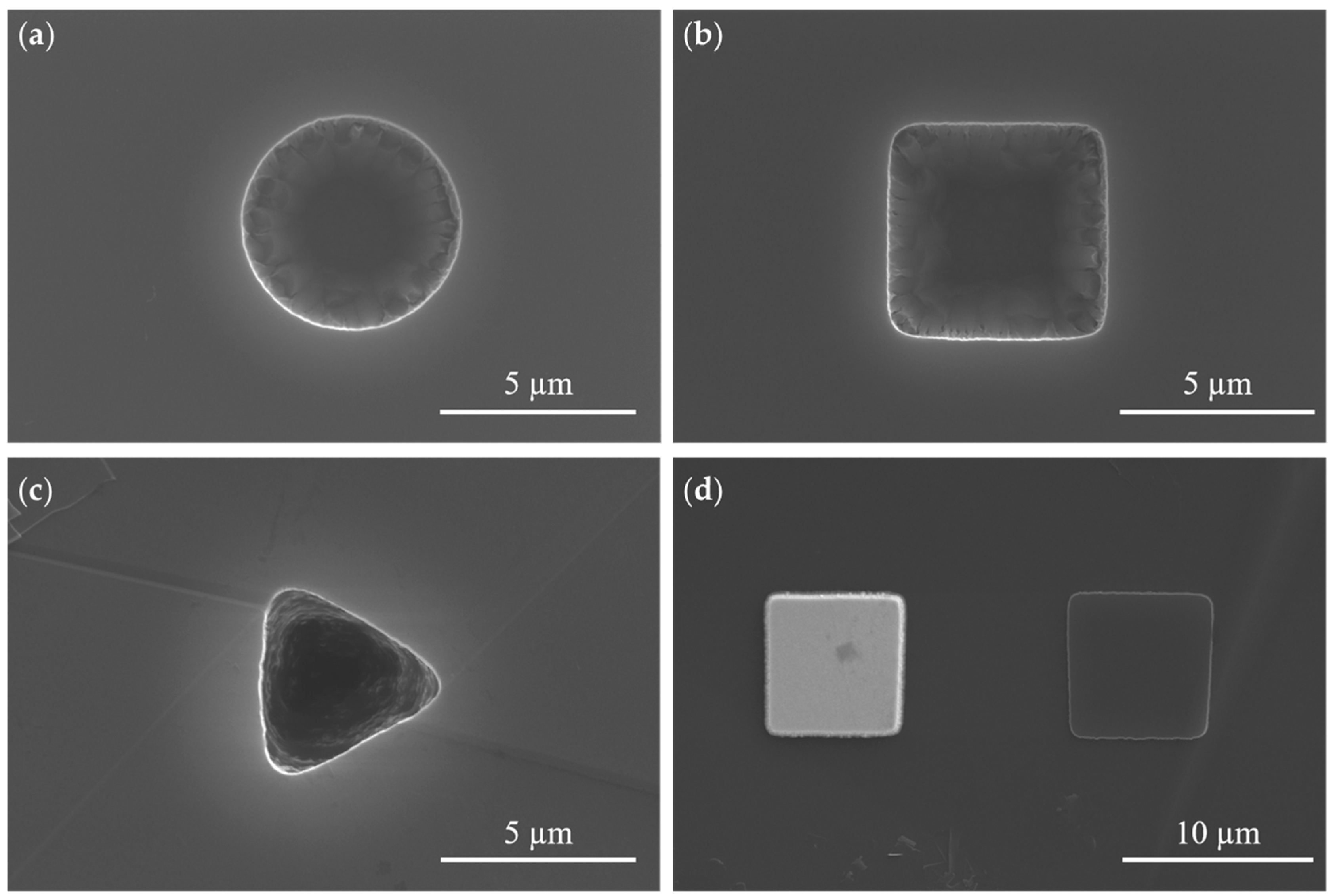
The morphology and geometric accuracy of the patterned graphite holes were characterized using Scanning Electron Microscopy (SEM). Arrays of circular, square, and triangular holes with lateral dimensions of 2, 3, 4, 5, and 6 µm were fabricated. Representative SEM images of individual 5 µm circular, square, and triangular holes are shown in
Figure 2a–c.
The circular and square holes exhibit clear and continuous edges, indicating reliable pattern transfer during fabrication. The triangular holes are also well defined, although slight rounding is observed near the vertices, consistent with the resolution limits of standard photolithography. The hole and mesa dimensions measured directly from the SEM images agree well with the designed values, confirming the geometric fidelity of the patterned structures. The center–to–center spacing between adjacent holes was fixed at 20 µm to ensure that the measured friction could be attributed to a single hole’s edge.
Figure 2d shows the SEM image of an 8 µm × 8 µm graphite mesa, with the left panel showing the Au–coated mesa after etching and the right panel depicting the exposed region following its removal using a tungsten probe. The close agreement in lateral dimensions between the mesa and the underlying patterned region verifies the fidelity of the fabrication process.
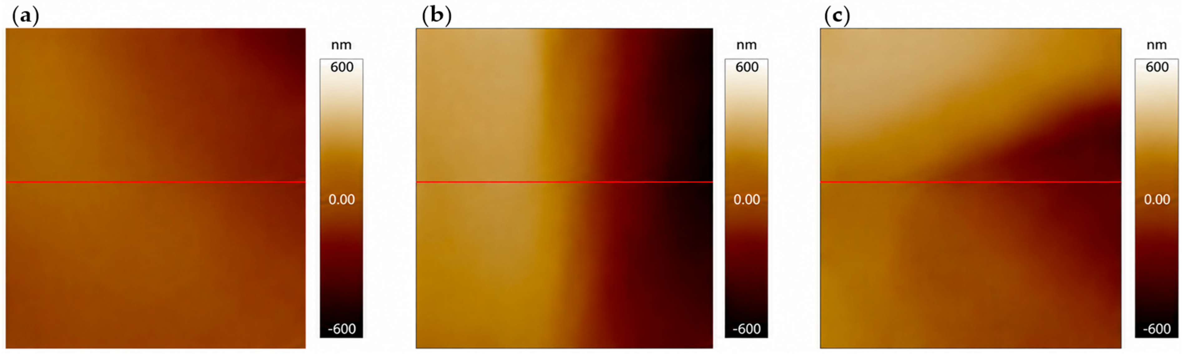
AFM characterization was performed to verify the structural integrity of the graphite surface surrounding the holes before friction measurements. Topography images acquired across the boundaries of the circular, square, and triangular holes (
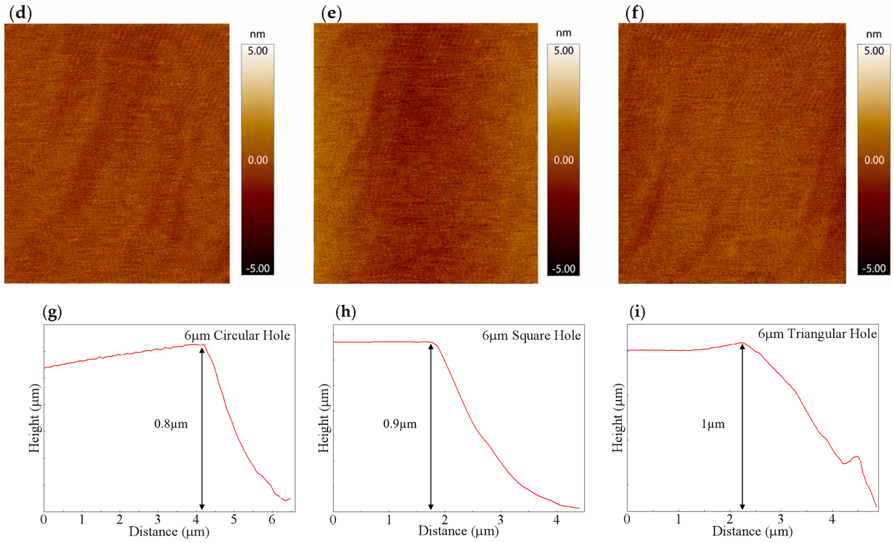
Figure 3a–c) demonstrate a smooth, well–defined transition from the atomically flat graphite surface to the hole edge. The corresponding height profiles in
Figure 3g–i exhibit a progressive decrease in height along the hole edges, reflecting a gradual transition from the graphite surface into the hole interior and confirming well–defined patterning of each geometric feature.
To further assess any potential process–induced modifications to the surrounding graphite, high–resolution topography images were acquired immediately adjacent to the hole perimeters (
Figure 3d–f), revealing that the graphite surface retains its atomically smooth character with no detectable residues, defects, or surface deformation attributable to the photolithography process. The roughness values summarized in
Table 1 show no systematic dependence on hole geometry or size, indicating that the graphite surfaces adjacent to the holes remain comparable across samples.
For each hole geometry and size, three different regions adjacent to the corresponding patterned hole edges were selected for AFM roughness characterization. The roughness parameters (Rq) and (Ra) were calculated from these three independent measurement regions and are reported as mean ± standard deviation in
Table 1. The roughness values are generally within the sub–nanometer range and show no systematic dependence on hole geometry or size, indicating that the graphite surfaces adjacent to the patterned holes remain morphologically comparable across samples. Although relatively larger standard deviations are observed for several square–hole regions, the absolute roughness remains low, suggesting that the friction enhancement cannot be attributed to systematic roughness variation in the surrounding graphite surface.
3. Results and Discussion
Having established the geometric accuracy of the holes and the comparable surface morphology of the graphite regions adjacent to the holes, we next investigate how these hole edges influence friction in the graphite/graphite interface.
3.1. Effect of Holes on Friction
All measurements were performed under identical Nano Tribological–Atomic Force Microscopy (NT–AFM) conditions using the same graphite mesa, with the cantilever calibrated in situ for both normal and lateral–force measurements. The normal spring constant was obtained using the Sader method [
27], which determines the cantilever stiffness from its resonance frequency, quality factor, and geometric parameters. The lateral force calibration was performed using a diamagnetic levitation spring system [
28], which provides a well–defined reference force for determining the cantilever’s torsional response.
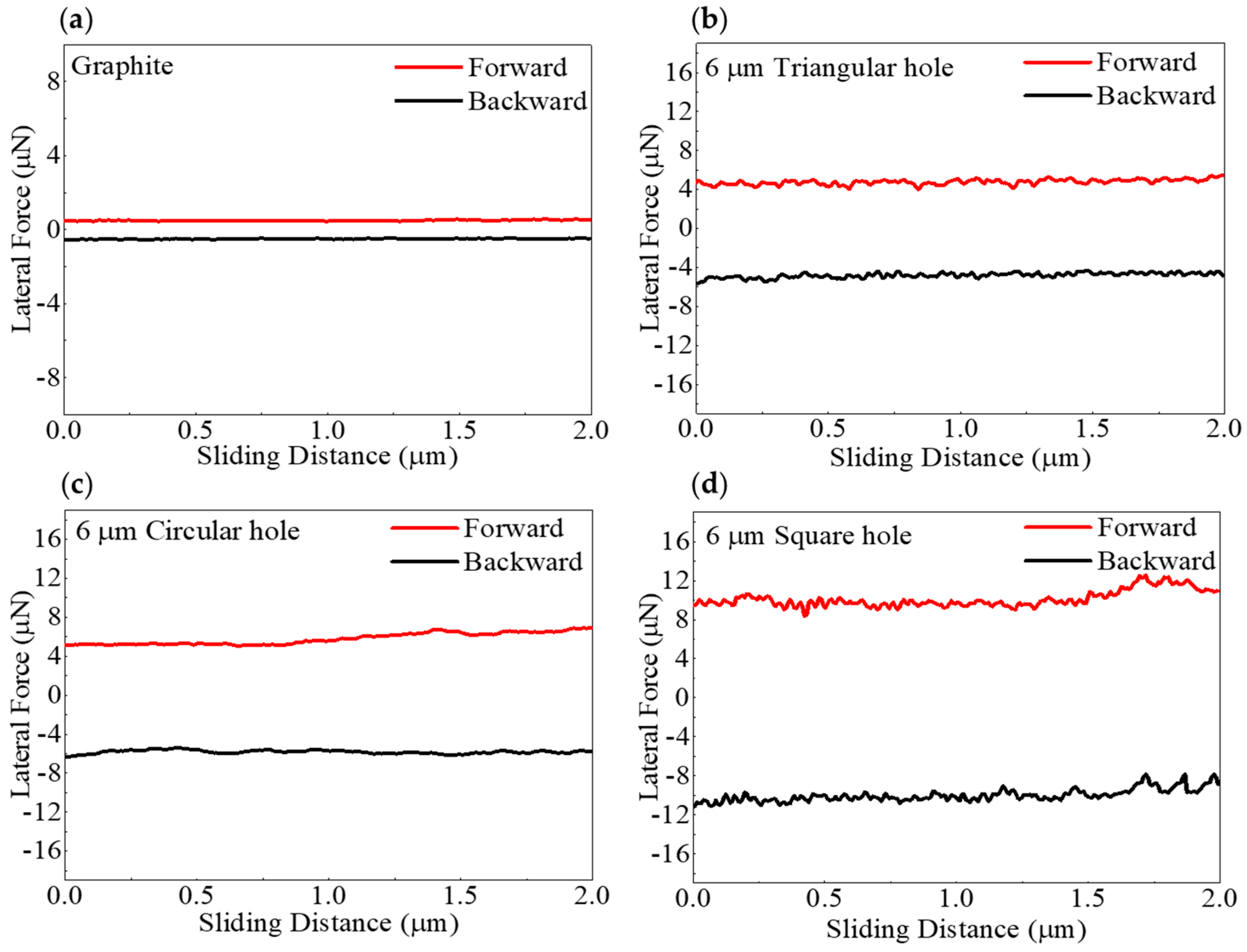
Figure 4a–d compare the lateral force signals recorded when an 8 µm × 8 µm graphite mesa slid on a single–crystal graphite/graphite interface and on 6 µm triangular, circular, and square holes, with a sliding distance of 2 µm.
The effect of hole boundaries on friction was investigated using AFM–based lateral sliding measurements, in which the AFM tip was used to push the graphite mesa across the hole following our previous measurement protocol [
29]. On the single–crystal graphite/graphite interface in
Figure 4a, the lateral force curves obtained during forward and backward scanning are nearly symmetric over the entire sliding distance, with a central friction force of approximately 0.2 µN, which is consistent with previously reported values for structurally superlubric graphite/graphite interfaces [
30], corresponding to about 3.1 kPa interfacial friction stress for a nominal 8 µm × 8 µm contact area. This friction stress level falls within the range reported for structural superlubric van der Waals interfaces [
3,
8,
20,
31]. This result reflects the intrinsic structural superlubricity of the graphite/graphite interface and provides a benchmark for evaluating the effect of hole boundaries on friction.
In contrast, when the graphite mesa slides across the triangular, circular, and square holes in
Figure 4b–d, the separation between the forward and backward traces increases markedly, indicating a substantial increase in lateral force at the graphite/graphite interface. For all three patterned configurations, the measured friction force was significantly higher than that of the non–patterned interface.
Importantly, this friction enhancement occurs despite the reduction in the real contact area caused by the holes. This opposing trend demonstrates that the increase in friction is not governed by the real contact area, but is primarily driven by additional interactions introduced at the hole edges. This result is inconsistent with the classical Bowden–Tabor framework, in which friction is expected to scale with the real contact area through interfacial shear strength [
32]. These results demonstrate that the edges of a hole play a dominant role in friction enhancement in an otherwise structurally superlubric graphite/graphite interface.
We also note that the friction associated with the hole edges is substantially larger than that arising from the edges of the graphite mesas themselves. This difference likely originates from the structural characteristics of the holes. Because the holes produced by microfabrication are not perfectly vertical (refer to the SEM and AFM images in
Figure 2 and
Figure 3), the in–plane sliding of the graphite mesa may simultaneously interact with edge segments at different heights near the hole boundary. In contrast, the low friction stress measured on the unpatterned graphite/graphite reference confirms that the basal–plane contact remains structurally superlubric, whereas the additional dissipation in the patterned samples originates primarily from the engineered hole edges [
6,
21,
33]. For this reason, the following discussion focuses primarily on the role of the hole edges in governing the observed frictional enhancement.
3.2. Dependence of Friction on Hole Perimeter
Because the graphite mesa remains fixed during measurements, variation in hole size directly alters the hole perimeter at the sliding interface.
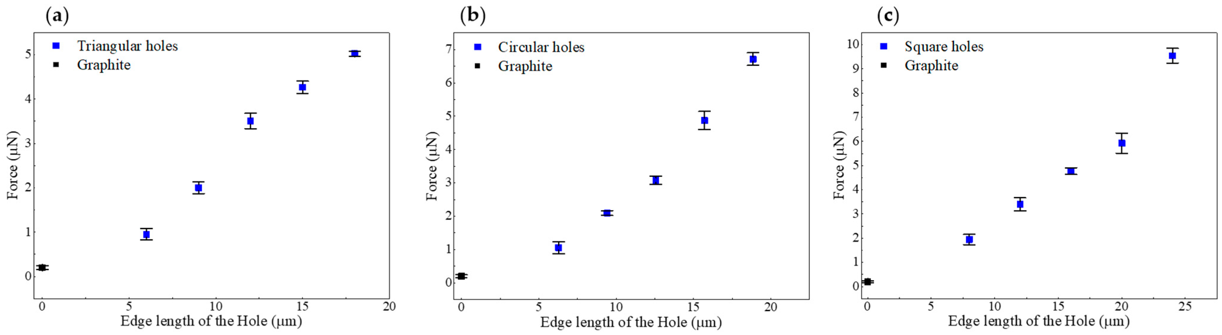
Figure 5 shows the friction measurements for triangular, circular, and square holes with characteristic sizes ranging from 2 to 6 µm. The graphite reference remains nearly constant at 0.2 µN, providing a narrow baseline for sliding friction on the graphite/graphite interface. The introduction of holes leads to a substantial increase in friction for all three geometries.
Figure 5 shows the AFM—measured lateral friction force plotted as a function of hole perimeter for triangular, circular, and square holes on a graphite substrate, using an 8 µm × 8 μm graphite mesa. For all hole geometries, the lateral friction force increases with increasing hole perimeter, showing a clear positive perimeter–dependent trend. In contrast, the graphite/graphite reference interface remains at a much lower friction level, as indicated by the black dots. The data shows that the friction force increases from 0.95 to 9.54 μN for holes as the characteristic edge length increases from 2 to 24 μm, with standard deviation error bars. These results demonstrate that all patterned structures exhibit significantly higher friction than the graphite/graphite interface, with friction increasing monotonically with edge length. With constant mesa size and sliding distance, increasing the hole perimeter increases the number of boundary sites involved in sliding.
Such boundary sites may locally disturb the translational symmetry of the graphite basal plane and enhance interfacial potential corrugation, thereby promoting localized pinning and additional energy dissipation during sliding [
14,
15,
16,
17,
18,
19,
20,
21]. Friction force scales linearly with hole perimeter according to the equation:
where
is a constant term representing the intrinsic interfacial friction of the graphite/graphite contact, α is the edge friction coefficient per unit length of hole boundary, and
L is the total hole perimeter.
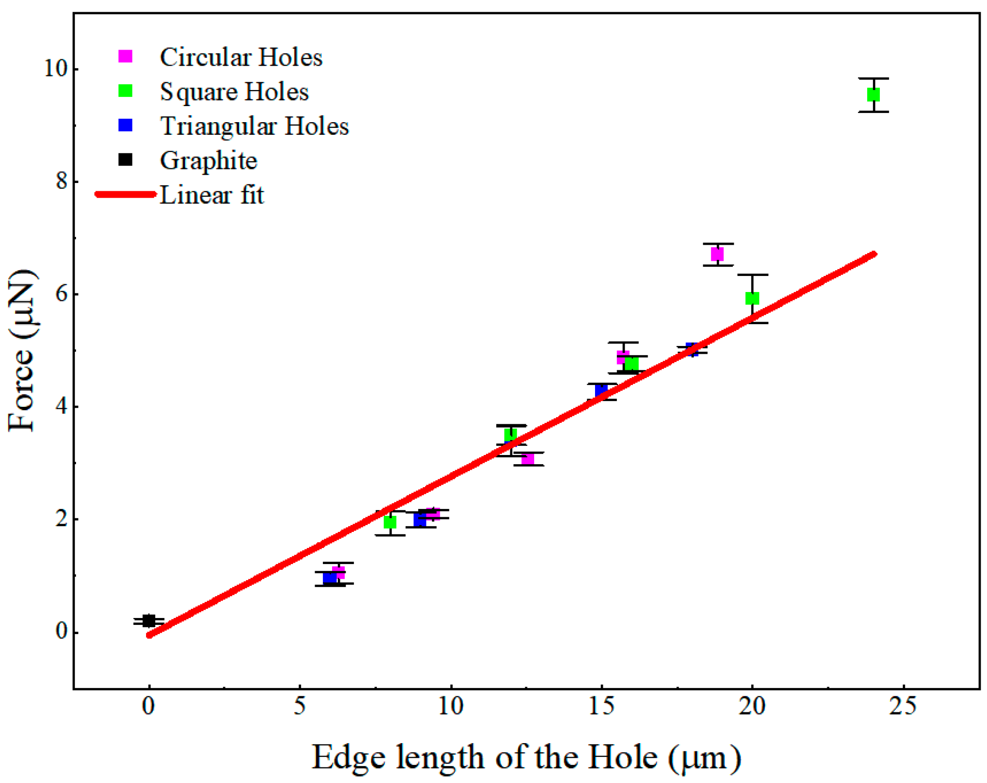
Figure 6 shows that the linear regression across all datasets yields a slope of
α = 0.282 ± 0.016 μN/μm, corresponding to a perimeter–normalized increase in lateral force of approximately 0.282 μN per micrometer of the hole boundary. The fitted intercept is
= −0.052 ± 0.194 μN. The Pearson correlation coefficient
r = 0.977, coefficient of determination
R2 = 0.954, and adjusted
R2 = 0.951 confirm an excellent linear relationship between friction force and hole perimeter. Because this intercept is obtained by extrapolating the finite–perimeter patterned–hole data to
L = 0, it should not be interpreted as the physical friction force of the graphite/graphite interface. Instead, the fitted slope α is the more physically relevant parameter, representing the friction enhancement introduced by engineered hole edges.
In this description, the graphite/graphite contact contributes only a small background friction term, whereas each additional unit length of engineered hole boundary contributes an approximately constant increment to the measured lateral force. This linear scaling supports the interpretation that friction enhancement is governed primarily by the cumulative length of edge–related pinning sites, rather than by the superlubric graphite/graphite contact area. This edge–dominated interpretation is consistent with previous studies showing that less–confined and structurally flexible edge atoms in van der Waals interfaces can act as localized pinning sites during sliding [
7,
18,
19,
20,
21,
34,
35].
3.3. Stability of the Edge–Dependent Frictional Response over Repeated Sliding Cycles
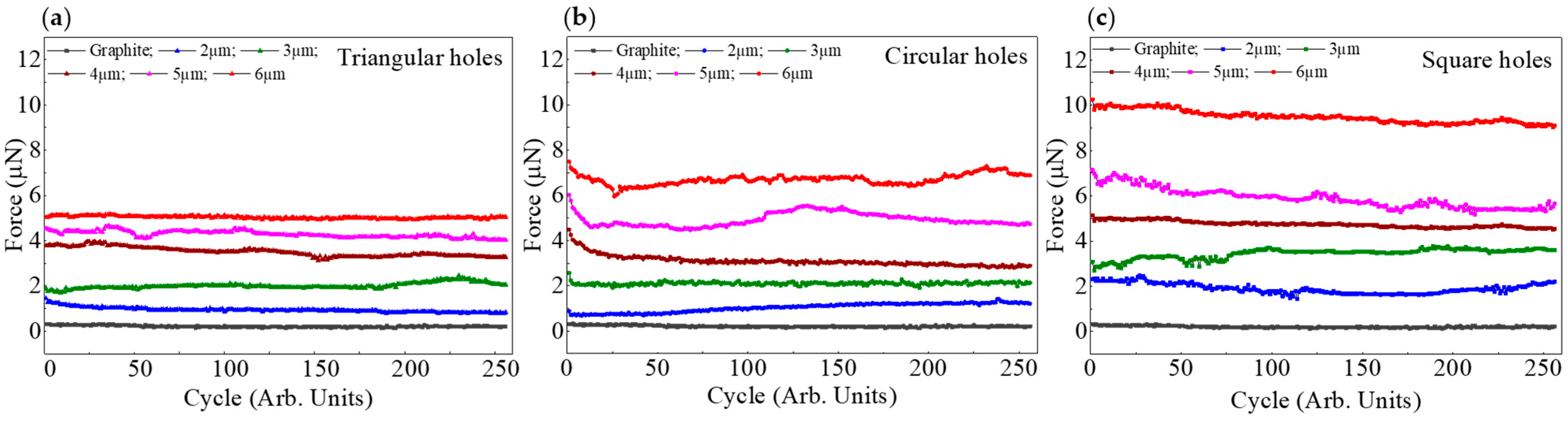
To assess the robustness of the observed edge–dependent frictional behaviour, the friction response was further examined over 256 sliding cycles for different hole geometries and sizes, as shown in
Figure 7. For the graphite/graphite interface, the friction force remains lowest throughout the entire measurement, with only minimal fluctuations, confirming the high stability of the structural superlubric graphite/graphite interface under repeated sliding.
In contrast, all patterned samples exhibit consistently higher friction levels than the graphite reference throughout the cycling process. Although some curves exhibit modest fluctuations or initial transient behaviour in the early cycles, no abrupt failure or catastrophic drift is observed. The overall friction hierarchy among the different patterned structures is largely maintained throughout the repeated sliding cycles, indicating that the friction enhancement introduced by the hole boundaries is not a transient artifact but a stable interfacial response. It implies that interfacial friction can be tuned by controlled variation in edge length.
4. Conclusions
This work demonstrates that friction at structurally superlubric graphite/graphite interfaces can be tuned by deliberately engineering internal hole edges. The introduction of holes systematically increases the measured friction force above that of an atomically smooth graphite/graphite reference interface, even though the nominal contact area is reduced. This finding shows that edge–mediated interactions constitute an independent and controllable dissipation channel in otherwise structurally superlubric interfaces.
By varying the geometry and size of the holes, we further show that the friction force scales approximately linearly with the total engineered edge length within the investigated geometric range. This result establishes total hole–edge length as a reliable geometric design parameter, distinct from conventional contact–area–based descriptions of friction. The repeated–cycle measurements further indicate that the edge–dependent friction enhancement is structurally encoded in the patterned interface: the engineered hole edges remain persistent geometric features during sliding, while the basal–plane regions retain their structurally superlubric character.
These results highlight geometric boundary engineering as a practical strategy for regulating friction in layered–material interfaces without changing material composition, applied load, or environmental conditions. Future work combining atomic–resolution edge characterization, spectroscopic mapping of edge chemistry and electronic states, molecular dynamics simulations, and first–principles calculations will be needed to clarify the relative contributions of phonon excitation, electrostatic pinning, and local stress concentration to edge–mediated friction.
Author Contributions
Conceptualization, D.P. and J.Z.; methodology, Y.P., H.L. and J.Z.; investigation, Y.P. and H.L.; validation, Y.P., H.L. and J.Z.; formal analysis, Y.P., H.L. and J.Z.; data curation, Y.P., H.L. and J.Z.; writing—original draft preparation, Y.P. and J.Z.; writing—review and editing, J.Z.; visualization, Y.P., H.L. and J.Z.; supervision, J.Z.; project administration, J.Z.; funding acquisition, D.P. and J.Z. All authors have read and agreed to the published version of the manuscript.
Funding
This work was supported by the National Key R&D Program of China (No. 2023YFB4603604), the National Natural Science Foundation of China (Grant No. 12574037), Shenzhen Science and Technology Program (No. KQTD20240729102211015, No. JCYJ20210324100600001), Shenzhen Key Laboratory of Superlubricity Technology (No. ZDSYS20230626091701002), and the National Natural Science Foundation of Guangdong Province (No. 2025A1515012226).
Data Availability Statement
The data presented in this study are available from the corresponding author upon reasonable request.
Conflicts of Interest
The authors declare no conflicts of interest.
References
- Holmberg, K.; Erdemir, A. Influence of tribology on global energy consumption, costs and emissions. Friction 2017, 5, 263–284. [Google Scholar] [CrossRef]
- Bhushan, B. Tribology on the macroscale to nanoscale of microelectromechanical system materials: A review. Proc. Inst. Mech. Eng. Part J J. Eng. Tribol. 2001, 215, 1–18. [Google Scholar] [CrossRef]
- Hod, O.; Meyer, E.; Zheng, Q.; Urbakh, M. Structural superlubricity and ultralow friction across the length scales. Nature 2018, 563, 485–492. [Google Scholar] [CrossRef] [PubMed]
- Berman, D.; Erdemir, A.; Sumant, A.V. Approaches for achieving superlubricity in two–dimensional materials. ACS Nano 2018, 12, 2122–2137. [Google Scholar] [CrossRef] [PubMed]
- Liu, Z.; Yang, J.; Grey, F.; Liu, J.Z.; Liu, Y.; Wang, Y.; Yang, Y.; Cheng, Y.; Zheng, Q. Observation of microscale superlubricity in graphite. Phys. Rev. Lett. 2012, 108, 205503. [Google Scholar] [CrossRef] [PubMed]
- Liao, M.; Nicolini, P.; Du, L.; Yuan, J.; Wang, S.; Yu, H.; Tang, J.; Cheng, P.; Watanabe, K.; Taniguchi, T.; et al. Ultra–low friction and edge–pinning effect in large–lattice–mismatch van der Waals heterostructures. Nat. Mater. 2022, 21, 47–53. [Google Scholar] [CrossRef] [PubMed]
- Li, Y.; He, W.; He, Q.C.; Wang, W. Contributions of edge and internal atoms to the friction of two–dimensional heterojunctions. Phys. Rev. Lett. 2024, 133, 126202. [Google Scholar] [CrossRef] [PubMed]
- Peng, D.; Wang, J.; Jiang, H.; Zhao, S.; Wu, Z.; Tian, K.; Ma, M.; Zheng, Q. 100 km wear–free sliding achieved by microscale superlubric graphite/DLC heterojunctions under ambient conditions. Natl. Sci. Rev. 2022, 9, nwab109. [Google Scholar] [CrossRef] [PubMed]
- Zheng, Q.; Jiang, B.; Liu, S.; Weng, Y.; Lu, L.; Xue, Q.; Zhu, J.; Jiang, Q.; Wang, S.; Peng, L. Self–retracting motion of graphite microflakes. Phys. Rev. Lett. 2008, 100, 067205. [Google Scholar] [CrossRef] [PubMed]
- Song, Y.; Wang, J.; Wang, Y.; Urbakh, M.; Zheng, Q.; Ma, M. Directional anisotropy of friction in microscale superlubric graphite/hBN heterojunctions. Phys. Rev. Mater. 2021, 5, 084002. [Google Scholar] [CrossRef]
- Han, M.; Peng, D.; Yang, D.; Wang, J.; Zheng, Y.; Hu, G.; Shao, Y.; Li, J.; Ding, F.; Xu, Z.; et al. Observation of robust macroscale structural superlubricity. Phys. Rev. Lett. 2026, 136, 076201. [Google Scholar] [CrossRef] [PubMed]
- Wang, Y.; Huang, Z.; Li, T.; Zheng, C.; Shao, Y.; Yang, D.; Lei, Y.; Xu, Z.; Zheng, Q.; Peng, D. Defect filtering in polycrystalline graphite: Self–selection of pristine interfaces enabling deterministic structural superlubricity. Fundam. Res. 2026; in press. [CrossRef]
- Vasić, B.; Milošević, I.; Konstantinović, Z.; Ognjanović, M.; Pomar, A. Nanoscale structural superlubricity in solution–processed graphene films via tribo–induced transfer layers. Carbon 2025, 244, 120697. [Google Scholar] [CrossRef]
- Koren, E.; Duerig, U. Moiré scaling of the sliding force in twisted bilayer graphene. Phys. Rev. B 2016, 94, 045401. [Google Scholar] [CrossRef]
- Ying, P.; Gao, X.; Berman, D.; Hod, O.; Urbakh, M. Scaling–up of structural superlubricity: Challenges and opportunities. Adv. Funct. Mater. 2025, 35, 2423024. [Google Scholar] [CrossRef]
- Gao, X.; Yan, W.; Ouyang, W.; Liu, Z.; Urbakh, M.; Hod, O. Frictional dissipation and scaling laws at van der Waals interfaces: The role of edge and corner elastic moiré pinning. ACS Nano 2025, 19, 29255–29264. [Google Scholar] [CrossRef] [PubMed]
- Liu, Y.; Ren, J.; Kong, D.; Shan, G.; Dou, K. Edge–pinning effect of graphene nanoflakes sliding atop graphene. Mater. Today Phys. 2023, 38, 101266. [Google Scholar] [CrossRef]
- van Wijk, M.M.; Dienwiebel, M.; Frenken, J.W.M.; Fasolino, A. Superlubric to stick–slip sliding of incommensurate graphene flakes on graphite. Phys. Rev. B 2013, 88, 235423. [Google Scholar] [CrossRef]
- Song, Y.; Gao, X.; Pawlak, R.; Huang, S.; Hinaut, A.; Glatzel, T.; Hod, O.; Urbakh, M.; Meyer, E. Non–Amontons frictional behaviors of grain boundaries at layered material interfaces. Nat. Commun. 2024, 15, 9487. [Google Scholar] [CrossRef] [PubMed]
- Wang, J.; Vanossi, A.; Tosatti, E. Effective stick–slip parameter for structurally lubric two–dimensional interface friction. Phys. Rev. B 2024, 109, 134102. [Google Scholar] [CrossRef]
- Hu, H.; Wang, J.; Tian, K.; Zheng, Q.; Ma, M. Effects of disordered edge and vanishing friction in microscale structural superlubric graphite contact. Nat. Commun. 2024, 15, 10830. [Google Scholar] [CrossRef] [PubMed]
- Mandelli, D.; Guerra, R.; Ouyang, W.; Urbakh, M.; Vanossi, A. Static friction boost in edge–driven incommensurate contacts. Phys. Rev. Mater. 2018, 2, 046001. [Google Scholar] [CrossRef]
- Gao, X.; Ouyang, W.; Urbakh, M.; Hod, O. Superlubric polycrystalline graphene interfaces. Nat. Commun. 2021, 12, 5694. [Google Scholar] [CrossRef] [PubMed]
- Gao, X.; Ouyang, W.; Hod, O.; Urbakh, M. Mechanisms of frictional energy dissipation at graphene grain boundaries. Phys. Rev. B 2021, 103, 045418. [Google Scholar] [CrossRef]
- Guo, Z.; Chang, T.; Guo, X.; Gao, H. Thermal–induced edge barriers and forces in interlayer interaction of concentric carbon nanotubes. Phys. Rev. Lett. 2011, 107, 105502. [Google Scholar] [CrossRef] [PubMed]
- Chen, L.; Lin, C.; Shi, D.; Huang, X.; Zheng, Q.; Nie, J.; Ma, M. Fully automatic transfer and measurement system for structural superlubric materials. Nat. Commun. 2023, 14, 6323. [Google Scholar] [CrossRef] [PubMed]
- Sader, J.E.; Larson, I.; Mulvaney, P.; White, L.R. Method for the calibration of atomic force microscope cantilevers. Rev. Sci. Instrum. 1995, 66, 3789–3798. [Google Scholar] [CrossRef]
- Li, Q.; Kim, K.S.; Rydberg, A. Lateral force calibration of an atomic force microscope with a diamagnetic levitation spring system. Rev. Sci. Instrum. 2006, 77, 065105. [Google Scholar] [CrossRef]
- Huang, X.; Li, T.; Wang, J.; Xia, K.; Tan, Z.; Peng, D.; Xiang, X.; Liu, B.; Ma, M.; Zheng, Q. Robust microscale structural superlubricity between graphite and nanostructured surface. Nat. Commun. 2023, 14, 2931. [Google Scholar] [CrossRef] [PubMed]
- Qu, C.; Wang, K.; Wang, J.; Gongyang, Y.; Carpick, R.W.; Urbakh, M.; Zheng, Q. Origin of friction in superlubric graphite contacts. Phys. Rev. Lett. 2020, 125, 126102. [Google Scholar] [CrossRef] [PubMed]
- Song, Y.; Qu, C.; Ma, M.; Zheng, Q. Structural superlubricity based on crystalline materials. Small 2020, 16, 1903018. [Google Scholar] [CrossRef] [PubMed]
- Philip, B.F.; Tabor, D. The Friction and Lubrication of Solids; Oxford University Press: Oxford, UK, 2001; Volume 9. [Google Scholar] [CrossRef]
- Benassi, A.; Ma, M.; Urbakh, M.; Vanossi, A. The breakdown of superlubricity by driving–induced commensurate dislocations. Sci. Rep. 2015, 5, 16134. [Google Scholar] [CrossRef] [PubMed]
- Ma, M.; Benassi, A.; Vanossi, A.; Urbakh, M. Critical length limiting superlow friction. Phys. Rev. Lett. 2015, 114, 055501. [Google Scholar] [CrossRef] [PubMed]
- Gigli, L.; Kawai, S.; Guerra, R.; Manini, N.; Pawlak, R.; Feng, X.; Müllen, K.; Ruffieux, P.; Fasel, R.; Tosatti, E.; et al. Graphene nanoribbons on gold: Understanding superlubricity and edge effects. 2D Mater. 2017, 5, 045003. [Google Scholar] [CrossRef]
Figure 1.
Schematic overview of the (a) fabrication strategy for creating atomically smooth graphite surfaces with microscale hole patterns and the construction of structurally superlubric graphite mesas on holes. (b) graphite mesa reciprocating motion, showing the sliding direction (red arrows), sliding distance (stroke length), and the step size between neighbouring holes in the patterned graphite substrate.
Figure 1.
Schematic overview of the (a) fabrication strategy for creating atomically smooth graphite surfaces with microscale hole patterns and the construction of structurally superlubric graphite mesas on holes. (b) graphite mesa reciprocating motion, showing the sliding direction (red arrows), sliding distance (stroke length), and the step size between neighbouring holes in the patterned graphite substrate.
Figure 2.
SEM images of patterned graphite holes represent (a) circular, (b) square, and (c) triangular holes, respectively. (d) SEM image of an 8 µm × 8 µm graphite mesa with an Au cap.
Figure 2.
SEM images of patterned graphite holes represent (a) circular, (b) square, and (c) triangular holes, respectively. (d) SEM image of an 8 µm × 8 µm graphite mesa with an Au cap.
Figure 3.
AFM characterization of the graphite holes with different geometries. Topography images acquired across the edge of (a) circular, (b) square, and (c) triangular holes (The red lines in the AFM height images indicate the line–scan positions used to extract the corresponding height profiles shown below each image) and images (d–f) represent the surface topography of the graphite around the holes. Figures (g–i) represent the corresponding height profiles extracted along the indicated scan direction for each geometry.
Figure 3.
AFM characterization of the graphite holes with different geometries. Topography images acquired across the edge of (a) circular, (b) square, and (c) triangular holes (The red lines in the AFM height images indicate the line–scan positions used to extract the corresponding height profiles shown below each image) and images (d–f) represent the surface topography of the graphite around the holes. Figures (g–i) represent the corresponding height profiles extracted along the indicated scan direction for each geometry.
Figure 4.
Lateral force signals recorded during NT–AFM sliding measurements with an 8 µm × 8 µm graphite mesa on (a) graphite surface, (b) 6 µm triangular hole, (c) 6 µm circular hole, and (d) 6 µm square hole. The forward and backward traces are shown as a function of sliding distance. All measurements were performed at a constant deflection setpoint of 30 nA and a scan rate of 1 Hz under identical experimental conditions.
Figure 4.
Lateral force signals recorded during NT–AFM sliding measurements with an 8 µm × 8 µm graphite mesa on (a) graphite surface, (b) 6 µm triangular hole, (c) 6 µm circular hole, and (d) 6 µm square hole. The forward and backward traces are shown as a function of sliding distance. All measurements were performed at a constant deflection setpoint of 30 nA and a scan rate of 1 Hz under identical experimental conditions.
Figure 5.
Lateral friction force measured by AFM as a function of hole perimeter using an 8 µm × 8 µm graphite mesa for (a) triangular, (b) circular, and (c) square holes on a graphite substrate. The friction of the graphite/graphite interface is included as a reference (black dots).
Figure 5.
Lateral friction force measured by AFM as a function of hole perimeter using an 8 µm × 8 µm graphite mesa for (a) triangular, (b) circular, and (c) square holes on a graphite substrate. The friction of the graphite/graphite interface is included as a reference (black dots).
Figure 6.
Linear fitting and residual analysis of the relationship between friction force and total hole–edge length. Lateral friction force as a function of total hole–edge length for circular, square, and triangular holes. The red line represents the linear fit.
Figure 6.
Linear fitting and residual analysis of the relationship between friction force and total hole–edge length. Lateral friction force as a function of total hole–edge length for circular, square, and triangular holes. The red line represents the linear fit.
Figure 7.
Frictional force as a function of sliding cycle for patterned graphite interfaces containing (a) triangular, (b) circular, and (c) square holes with sizes from 2 to 6 µm.
Figure 7.
Frictional force as a function of sliding cycle for patterned graphite interfaces containing (a) triangular, (b) circular, and (c) square holes with sizes from 2 to 6 µm.
Table 1.
Surface roughness characterization of regions adjacent to the patterned hole edges measured by AFM. The (Rq) and (Ra) values are reported as mean ± standard deviation from three different AFM measurement regions adjacent to the corresponding hole edges for each hole geometry and size.
Table 1.
Surface roughness characterization of regions adjacent to the patterned hole edges measured by AFM. The (Rq) and (Ra) values are reported as mean ± standard deviation from three different AFM measurement regions adjacent to the corresponding hole edges for each hole geometry and size.
| Shape/Size of the Holes (µm) | Triangle | Circle | Square |
|---|
| Rq (pm) | Ra (pm) | Rq (pm) | Ra (pm) | Rq (pm) | Ra (pm) |
|---|
| 2 | 220.32 ± 2.82 | 173.82 ± 2.24 | 226.23 ± 11.80 | 180.13 ± 9.24 | 210.85 ± 14.52 | 167.74 ± 12.10 |
| 3 | 238.04 ± 14.84 | 189.81 ± 11.62 | 215.39 ± 11.41 | 171.59 ± 9.27 | 301.31 ± 69.62 | 238.33 ± 28.04 |
| 4 | 213.22 ± 4.02 | 170.29 ± 2.67 | 227.96 ± 22.48 | 181.68 ± 18.05 | 207.43 ± 7.33 | 164.71 ± 5.58 |
| 5 | 299.97 ± 9.55 | 210.18 ± 7.89 | 215.03 ± 3.11 | 171.46 ± 2.30 | 329.24 ± 29.16 | 202.71 ± 6.92 |
| 6 | 218.82 ± 4.56 | 173.98 ± 3.48 | 209.35 ± 0.57 | 165.79 ± 2.50 | 222.02 ± 56.94 | 177.77 ± 32.27 |
| Disclaimer/Publisher’s Note: The statements, opinions and data contained in all publications are solely those of the individual author(s) and contributor(s) and not of MDPI and/or the editor(s). MDPI and/or the editor(s) disclaim responsibility for any injury to people or property resulting from any ideas, methods, instructions or products referred to in the content. |