Article

Coupled Model of Point-Contact Thermo-Elastohydrodynamic Lubrication and Dynamics with Double-Impact Mechanism for High-Precision Quantitative Diagnosis of Rolling Bearings


1
Inner Mongolia Key Laboratory of Intelligent Diagnosis and Control of Mechatronic System, Inner Mongolia University of Science and Technology, Baotou 014010, China
2
Department of Chemical and Materials Engineering, Baotou Light Industry Vocational Technical College, Baotou 014035, China
3
State Key Laboratory of Tribology, Department of Mechanical Engineering, Tsinghua University, Beijing 100080, China
4
Inner Mongolia Institute of Special Equipment Inspection and Research, Energy Equipment Intelligent Inspection and Safety Assurance Laboratory, Baotou 010020, China
*
Author to whom correspondence should be addressed.
Lubricants 2026, 14(7), 261; https://doi.org/10.3390/lubricants14070261
Submission received: 20 May 2026 / Revised: 24 June 2026 / Accepted: 26 June 2026 / Published: 30 June 2026

Abstract

Accurate quantitative diagnosis of spall sizes in rolling bearings is often hindered by the limitations of conventional dynamic models in characterizing temperature-dependent contact behavior. To address this issue, this paper presents a quantitative diagnosis method that incorporates point-contact thermo-elastohydrodynamic lubrication (TEHL) characteristics into a classical bearing dynamic framework. Specifically, rather than using prescribed or constant contact parameters, an improved equivalent stiffness–damping representation of the bearing contact interface is formulated based on TEHL-derived oil-film pressure, thickness, and temperature, while taking into account the inner–outer raceway thermal asymmetry. This localized lubricated contact representation is subsequently integrated into a classical five-degree-of-freedom (5-DOF) dynamic model to evaluate the double-impact response caused by outer-ring spalls. Comparative simulations using conventional 5-DOF, 4-DOF, and 2-DOF models, alongside experiments on a 6205-2-RS bearing with a 0.6 mm outer-ring defect, validate the proposed method. The results demonstrate that utilizing the TEHL-derived stiffness–damping representation significantly reduces spall-size estimation errors, improving both the accuracy and the physical interpretability of bearing fault quantification under thermally coupled conditions.

1. Introduction

Rolling bearings are key supporting components in rotating machinery, and their contact state, lubrication condition, and vibration response directly affect operational stability and fault evolution. For deep-groove ball bearings widely used in motors, pumps, machine tools, and automated production lines, localized defects such as raceway spalls, pitting, and local wear alter the load-transfer path between rolling elements and raceways and generate distinct impact features in the time-domain response. Accurate spall-size quantification therefore depends not only on signal-processing results, but also on the capability of dynamic models to describe contact force, stiffness/damping variation, and defect-induced excitation. Introducing lubricant-film behavior and thermal effects into localized-defect modeling is important for improving the reliability of spall-size estimation.
The rolling element–raceway contact is commonly simplified as Hertzian contact. Under lubricated operating conditions, however, oil-film pressure, film thickness, and temperature affect the load-carrying capacity, energy dissipation, and dynamic transmission characteristics of the contact interface. Zhang et al. [1] considered temperature effects in rolling-bearing dynamics, but did not explicitly introduce lubricant-film states into the contact parameters. The coupling between lubricated contact and bearing dynamics has been studied in tribodynamics: Rahnejat and Gohar [2] represented lubricated radial ball bearings by nonlinear spring–damper elements in rotor–bearing vibration analysis; Wijnant et al. [3] examined lubrication effects on ball-bearing dynamics; Sarangi et al. [4] formulated stiffness and damping coefficients for mixed-lubricated ball bearings; Mohammadpour et al. [5] developed a transient thermal-mixed non-Newtonian EHL framework linking contact load, lubrication state, and vibration response; and Zhang et al. [6] studied the dynamic behavior of elastohydrodynamically lubricated rolling contacts. These studies provide the basis for incorporating EHL/TEHL contact behavior into bearing dynamic analysis.
For bearings with localized defects, dynamic models have evolved from ideal Hertzian formulations to models considering defect geometry, time-varying displacement excitation, oil-film stiffness, skidding, and lubrication thermal effects. Luo et al. [7] described the displacement and excitation force caused by rolling elements passing through an inner-race spall using piecewise functions. Gomez et al. [8] modeled localized defects based on instantaneous angular speed variations, while Jiang et al. [9] improved defective-bearing modeling by considering the three-dimensional rolling element–defect geometry. Yan et al. [10] established a 5-DOF model under isothermal EHL conditions and analyzed lubrication-dependent stiffness and vibration response. Tian et al. [11] coupled bearing dynamics with TEHL to study contact force, friction force, and oil-film temperature in high-speed angular contact ball bearings. Wang et al. [12] showed that thermal EHL changes oil-film pressure, film thickness, and vibration amplitude in defective bearings. Tian et al. [13] further introduced rolling element spin, revolution, skidding, and TEHL effects into defective deep-groove ball bearing dynamics. Huo et al. [14] investigated locally failed roller bearings under starved lubrication. Bai et al. [15] studied lubrication state transitions in thermally affected defective bearings. Huo et al. [16] analyzed outer-ring localized failure under starved lubrication, and Peng et al. [17] considered rolling element–defect boundary interaction within a point-contact mixed-lubrication framework. These studies have advanced lubricated dynamic modeling of defective bearings, but most focus on global vibration response, contact load, skidding behavior, lubrication state variation, or defect-boundary interaction. The relationship between TEHL contact parameters and double-impact time characteristics for outer-ring spall-size quantification remains insufficiently clarified.
Double-impact features provide a direct physical basis for spall-size quantification. When a rolling element enters and exits a spalled region, two impact events with different physical meanings may appear in the vibration response, and their time interval is closely related to the spall length. Epps [18] first indicated that this interval increases with defect size. Randall and Sawalhi [19] developed signal-processing tools for spall tracking, and Sawalhi and Randall [20] verified the difference between entry and exit responses. Ming et al. [21] established a dual-impulse model based on acoustic emission signals. Singh and Kumar [22] and Jena and Panigrahi [23] used wavelet decomposition and vibration analysis for defect-width measurement. More recently, He et al. [24], Wu et al. [25], and Luo et al. [26] advanced spall-size evaluation through cross-condition diagnosis, dual-impulse behavior analysis, physical modeling, and instantaneous vibration energy. These studies confirm that the double-impact interval is an important indicator for spall-size estimation.
Although EHL/TEHL bearing dynamics and double-impact-based defect quantification have both been widely investigated, they have mainly developed along different modeling routes. Existing EHL/TEHL dynamic studies clarify how lubrication affects contact load, stiffness/damping, skidding, and vibration response, whereas double-impact-based quantitative diagnosis usually estimates defect size from impact timing, defect geometry, or vibration features. For outer-ring spalls, the remaining issue is not whether lubrication affects bearing dynamics, but how the local TEHL state is transferred into the dynamic quantities that determine the double-impact interval. In particular, the influence of oil-film pressure, film thickness, temperature field, and inner–outer raceway thermal asymmetry on equivalent stiffness/damping, oil-film-related displacement excitation, rolling element–raceway contact force, and spall-size estimation has not been sufficiently described.
To address this issue, this study focuses on the outer-ring spall defect of an SKF 6205 deep-groove ball bearing and adopts a 5-DOF bearing dynamic framework with contact-interface parameters reformulated under point-contact TEHL conditions. The TEHL-derived oil-film pressure, film thickness, temperature field, and inner–outer raceway thermal asymmetry are converted into an equivalent stiffness–damping representation. These contact parameters are then introduced into the dynamic framework together with oil-film-thickness-related additional-displacement excitation and rolling element–raceway contact force, thereby establishing the relationship between local lubricated contact behavior and the macroscopic double-impact response. Finally, the outer-ring spall size is estimated using the double-impact time interval and validated through numerical simulations and experiments.

2. Point-Contact Thermo-Elastohydrodynamic Lubrication Theory and Bearing Characteristic Modeling

To overcome the limitation of neglecting temperature-dependent lubricant-film effects in conventional models, a point-contact TEHL-based framework is developed, enabling accurate characterization of oil-film pressure, thickness, and temperature coupling, and facilitating an improved stiffness–damping model for enhanced dynamic analysis.

2.1. Limitations of Traditional Bearing Stiffness and Damping Models

Temperature fluctuations during prolonged operation alter rolling-bearing material properties, disrupting their dynamic models and lubrication performance. Excessive temperature aggravates lubrication deficiency and localized overheating, making investigation of temperature-dependent elastohydrodynamic lubrication behavior of bearing lubricants critical. This study focuses on the 6205 deep-groove ball bearing, whose parameters listed in Table 1.
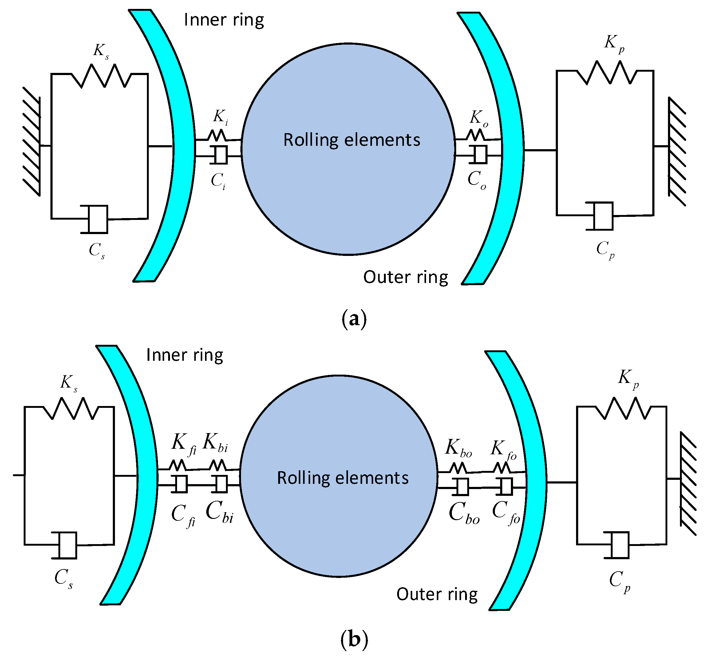
Figure 1 presents two simplified rolling-bearing stiffness–damping models under TEHL conditions. Both models (Figure 1a,b) neglect oil-film thermal effect under temperature variation, which causes misjudgment of bearing capacity and oil-film stiffness, deviation of dynamic simulation from actual working conditions, and significant bias in quantitative spall-size calculation. TEHL theory is thus introduced to correct this oversight, enabling more accurate quantitative fault diagnosis of rolling bearings via realistic characterization of oil-film properties and their influence on macroscopic bearing parameters.

2.2. Numerical Simulation Modeling of Point-Contact Thermo-Elastohydrodynamic Lubrication

2.2.1. Numerical Simulation Model Construction

To characterize the temperature-dependent lubricant-film behavior of the rolling element–raceway contact, a point-contact TEHL model is first established. The calculated oil-film pressure, film thickness, and temperature fields provide the local contact-state variables required for the subsequent stiffness–damping representation and dynamic formulation.
For the ball–inner/outer raceway point-contact conjunctions of the 6205 bearing, the TEHL numerical model is solved using a multigrid method by coupling the Reynolds equation, the viscosity–pressure–temperature relation, the density relation, the elastic deformation equation, and the energy equation. No. 4106 aviation lubricant is selected as the lubricating medium, and its parameters are listed in Table 2.
The point-contact TEHL model is used to obtain the lubricant-film pressure, film thickness, temperature field, and the corresponding oil-film stiffness/damping of the ball–raceway contact, which are subsequently introduced into the bearing dynamic model. Therefore, the local lubrication problem is treated as a quasi-steady point-contact TEHL problem, while the time-varying response caused by the outer-ring spall is described in the dynamic model.
(1)
Reynolds equation
For the SKF 6205 bearing, the ball–raceway contact is modeled as a fully flooded elliptical point contact. The x- and y-directions are defined along the rolling direction and the transverse direction of the contact ellipse, respectively. Surface motion is assumed to be dominated by rolling entrainment in the x-direction, with the entrainment velocity defined as u e = (u1 + u2)/2. The y-direction pressure-flow term is retained to describe transverse pressure diffusion, whereas lateral entrainment and the transient squeeze-film term 12 (ρh)/ t are not included in the local Reynolds equation. Under these assumptions, the Reynolds equation used in the point-contact TEHL calculation is written as
x ρ h 3 η p x + y ρ h 3 η p y = 12 u e ρ h x
where h is the oil-film thickness, p is the oil-film pressure, η is the lubricant viscosity, ρ is the lubricant density, and u e is the entrainment velocity in the rolling direction. In a fully transient TEHL formulation, the squeeze-film contribution is associated with the instantaneous normal approach or separation of the contacting surfaces. In this study, this impact-induced approach and separation are represented at the bearing-system level through the time-varying contact deformation, additional-displacement excitation, rolling element–raceway contact force, and TEHL-derived equivalent stiffness/damping, as described in Section 3.
(2)
Viscosity variation equation (dependent on pressure and temperature):
For the selected 4106 aviation lubricant, the viscosity in the point-contact TEHL calculation is evaluated as a function of the local pressure and temperature. The Roelands viscosity relation, expressed using Houpert’s pressure–viscosity and temperature–viscosity indices, is adopted as follows [27,28]:
η = η 0 exp ln η 0 + 9.67 × 1 + 1 + 5.1 × 10 9 p z 0 T 138 T 0 138 s 0
z 0 = α 5.1 × 10 9 ln η 0 + 9.67
s 0 = β T 0 138 ln η 0 + 9.67
where T 0 is the ambient temperature, T is the oil-film temperature, η 0 is the initial viscosity of the lubricant, α is the viscous pressure coefficient, β is the viscous temperature coefficient, and z 0 and s 0 are the pressure–viscosity index and temperature–viscosity index in the Roelands–Houpert formulation, respectively.
(3)
The lubricant density is described using the Dowson–Higginson density–pressure relation with a temperature correction [29]:
ρ = ρ 0 1 + 0.6 × 10 9 p 1 + 1.7 × 10 9 p 6.5 × 10 4 T T 0
where ρ 0 is the initial density of the lubricant.
(4)
Point-contact elastic deformation equation
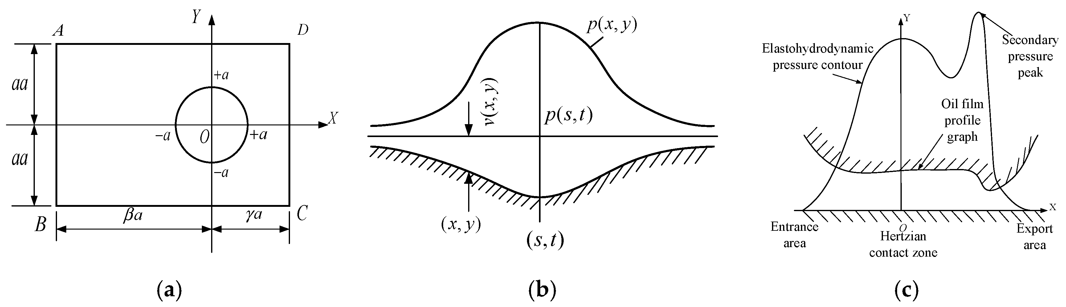
The solution domain for the point-contact deformation is a rectangular region, as shown in Figure 2a. In the solution domain, AB is defined as the entrance edge, CD as the exit edge, and AD and BC as the end drain edges.
Following the point-contact EHL formulation, the two elastic bodies are reduced to an equivalent elastic body and a rigid plane, as shown in Figure 2b. The local film thickness h x , y , consisting of the central film thickness, geometric separation, and pressure-induced elastic deformation v x , y , is expressed as [30]:
h x , y = h 0 + x 2 2 R x + y 2 2 R y + v x , y
v x , y = 2 π E Ω p s , t x s 2 + y t 2 d s d t
where h 0 is the undeformed central film thickness, R x and R y are the equivalent curvature radii, E is the equivalent elastic modulus, p s , t is the contact pressure, s and t are integration coordinates, and Ω is the solution domain.
The theoretical oil-film shape and elastohydrodynamic pressure distribution are shown in Figure 2c. The pressure distribution exhibits a typical secondary pressure peak near the outlet region.
(5)
The oil-film temperature field is obtained from the thermal EHL energy equation [31]:
c o ρ u T x + ρ v T y q T z = k o 2 T z 2 ρ T u T ρ p x + v T ρ p y + η u z 2 + v z 2
where k o represents the thermal conductivity of the lubricant, and c o denotes the specific heat capacity of the lubricant.
(6)
The heat transfer at the rolling element–lubricant and raceway–lubricant interfaces is described using thermal boundary conditions derived from moving heat-source theory [32]:
T ( x , y , 0 ) = k h π ρ 1 c 1 k 1 u 1 x T z x , y , 0   d s x s + T 0 ( x , y , h ) = k h π ρ 2 c 2 k 2 u 2 x T z x , y , h   d s x s + T 0
where ρ , c , k denote the density, specific heat capacity and heat transfer coefficient of the contact pair; subscripts 1 and 2 refer to the rolling element and raceway, respectively.

2.2.2. Analysis of Numerical Simulation Results

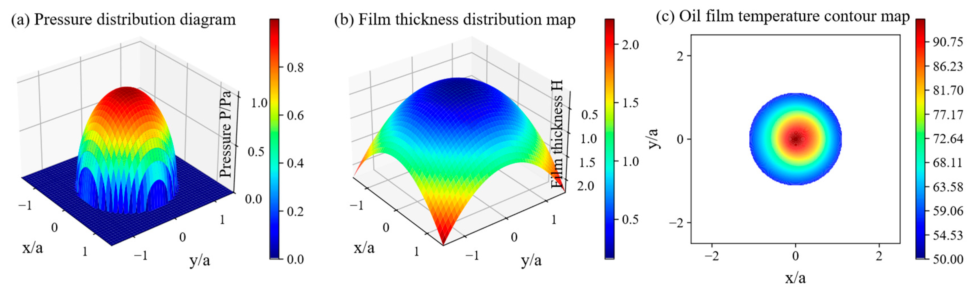
Via the aforementioned coupled equations and multigrid method, the pressure distribution, film thickness distribution and oil-film temperature map under the point-contact TEHL state are derived, as depicted in Figure 3a–c, respectively.
As shown in Figure 3a–c, the point-contact TEHL model presents typical elastohydrodynamic lubrication characteristics. The pressure distribution exhibits a secondary pressure peak near the outlet region, which is consistent with the theoretical distribution shown in Figure 2c and supports the validity of the model.

2.3. Improved Rolling-Bearing Stiffness and Damping Model Considering Thermo-Elastohydrodynamic Lubrication

2.3.1. Improved Bearing Stiffness and Damping Models

Under point-contact TEHL conditions, the rolling element is separated from the inner and outer raceways by lubricant films, forming an inner raceway–oil film–rolling element–oil film–outer raceway contact system. The solid-contact component of this system is described by the Hertzian load–deformation relation [33]. For the ball–raceway contact considered in this study, the nonlinear normal contact force is expressed as:
F = K   δ n
where F denotes the nonlinear contact force, δ is the contact deformation displacement, K is the contact stiffness coefficient, and n is the load–deflection index, which is usually taken as n = 1.5 for ball bearings.
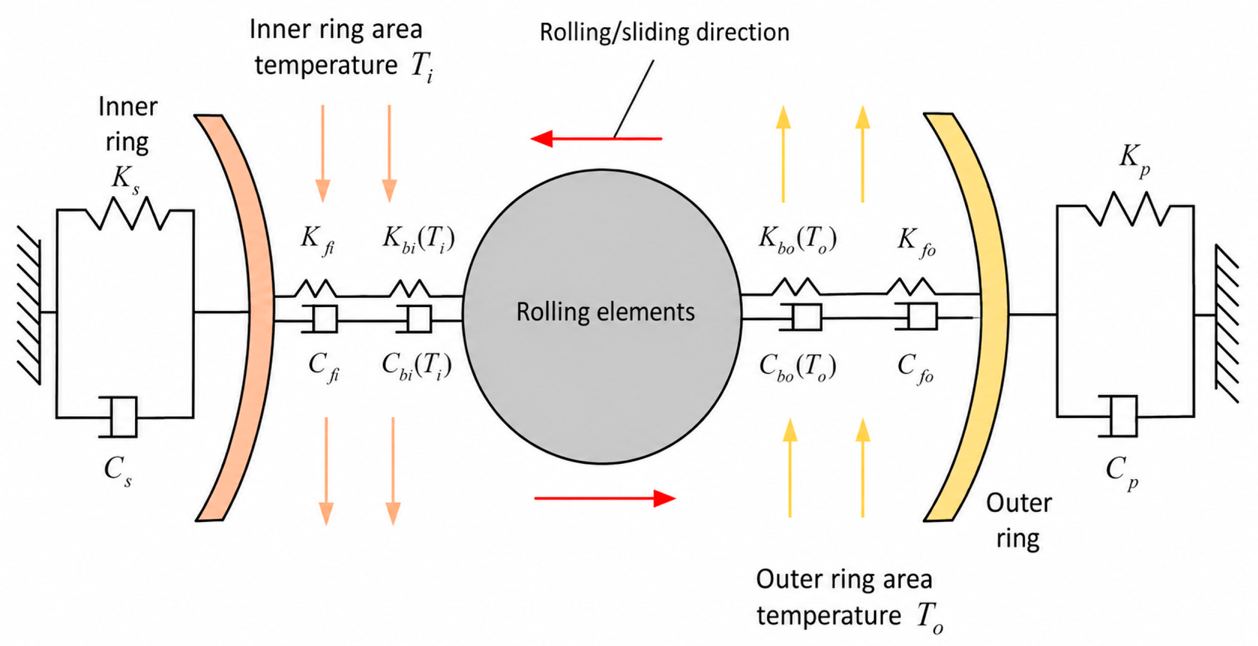
Under TEHL conditions, the rolling element–raceway contact is represented by the simplified stiffness–damping form shown in Figure 4.
Figure 4 shows the stiffness–damping representation of the bearing contact interface under TEHL conditions. In this representation, the rolling element–raceway contact is not described only by a prescribed Hertzian contact parameter. Instead, the inner- and outer-raceway contact characteristics are represented by the combined effects of Hertzian contact stiffness/damping and TEHL-derived oil-film stiffness/damping. Different temperature parameters are introduced for the inner and outer raceways to capture the thermal asymmetry of the lubricated contact. The minimum oil-film thickness and rotational speed are taken as the key variables for calculating the equivalent stiffness and damping. These equivalent parameters provide the contact-interface input for the subsequent 5-DOF dynamic formulation.

2.3.2. Rolling-Bearing Stiffness Calculation

The stiffness–damping representation of the bearing contact interface includes the Hertzian contact stiffness between the rolling elements and the inner/outer raceways and the lubricant-film stiffness. The Hertzian contact stiffness is calculated based on Hertzian contact theory and rolling-bearing contact analysis [33,34]:
K b i = 2 2 E 1 ν 2 3 ρ i 1 2 1 δ i 3 2 K b o = 2 2 E 1 ν 2 3 ρ o 1 2 1 δ o 3 2
where K b i , K b o represent the initial contact stiffnesses between rolling elements and the inner/outer raceways, respectively; ρ i , ρ o represent the curvatures of the inner/outer raceways; δ i , δ o   represent the contact displacements of unit magnitude for the inner/outer raceways; E represents the elastic modulus; and ν represents the Poisson’s ratio.
Under TEHL conditions, oil-film stiffness is defined as the ratio of the radial load to the radial deformation of the oil film. For the calculation of oil-film stiffness, the oil-film stiffness of the bearing’s inner/outer rings can be derived as follows:
K f i = K f o = lim δ 0 Δ ω δ = d ω d h = lim Δ 0   Δ Q max Δ h m t = Ω p x , y d x   d y h m t
where h m t denotes the minimum oil-film thickness under TEHL conditions.
The equivalent stiffness of the inner ring, K s , the equivalent stiffness of the outer ring, K p , and the integrated stiffness of the bearing, K b , are calculated as follows:
K s = K b i T i K f i K b i + K f i
K p = K b o T o K f o K b o T o + K f o
K b = K s K p K s + K p

2.3.3. Calculation of Rolling Bearing Damping

The calculation formula of the bearing’s structural damping under TEHL conditions is given as follows [35]:
C b i = C b o = η b k i o ω ext
where η b is the bearing structural loss factor, and ω ext is the excitation frequency. Under thermo-elastohydrodynamic lubrication, C b i represents the structural damping of the inner ring of the bearing and C b o represents the structural damping of the outer ring of the bearing as the initial structural damping, k i - o denotes the equivalent stiffness between the inner and outer rings of a rolling bearing.
Under TEHL conditions, oil-film damping is defined as the ratio of the variation in load acting on the oil film to the variation in contact velocity. The oil-film damping of the bearing’s inner and outer rings is given as follows:
C f i = C f o = lim Δ 0 Δ Q max Δ u s = Ω p x , y d x   d y u s
where C f i and C f o denote the TEHL-derived oil-film damping components of the rolling element–inner raceway contact and rolling element–outer raceway contact, respectively;   Δ Q max denotes the variation in the maximum oil-film load; Δ u s is the variation in relative sliding/contact velocity; p x , y denotes the pressure distribution in the contact area; and Ω is the integral domain of the contact area.
The equivalent damping C s of the inner ring, the equivalent damping C p of the outer ring, and the integrated damping C b of the bearing are calculated as follows:
C s = C i T i C f i C i T i + C f i
where C i T i represents the temperature-dependent structural/contact damping component of the inner-raceway side at temperature T i , C f i represents the TEHL-derived oil-film damping between the rolling element and the inner raceway, and C s is the equivalent damping of the inner-raceway side.
C p = C o T o C f o C o T o + C f o
where C o T o represents the temperature-dependent structural/contact damping component of the outer-raceway side at temperature T o , C f o represents the TEHL-derived oil-film damping between the rolling element and the outer raceway, and C p is the equivalent damping of the outer-raceway side.
C b = C s C p C s + C p
where C b is the total damping of the rolling bearing.
Based on Equations (11)–(20), the equivalent stiffness and damping of the inner- and outer-raceway contacts are obtained under point-contact TEHL conditions. These parameters combine the Hertzian solid-contact component with the lubricant-film component and include the temperature difference between the inner and outer raceways. The obtained equivalent stiffness and damping are then used as contact-interface parameters in the subsequent dynamic formulation.

3. Modeling and Quantitative Diagnostic Study of Rolling-Bearing Dynamics Under TEHL

Based on the point-contact TEHL model and the stiffness–damping representation developed in Section 2, this section introduces the TEHL-derived contact-interface parameters into a 5-DOF bearing dynamic framework to analyze the double-impact response of rolling bearings with outer-ring spall defects. The oil-film thickness, equivalent stiffness/damping, and contact force are then used to establish the relationship between the lubricated contact state and spall-size quantification.

3.1. Excitation Model for Additional Displacement of Rolling Element–Raceway Contact Under TEHL

Under TEHL conditions, lubricant films exist between the rolling element and the inner/outer raceways, so the rolling element–raceway contact displacement differs from that under dry-contact conditions. The lubricant film modifies the local contact clearance, load transfer, and energy dissipation, thereby affecting the double-impact response induced by outer-ring spalls. Therefore, the oil-film thickness is introduced into the additional-displacement excitation model to describe the variation in rolling element–raceway separation when the rolling element passes through the outer-ring spall.
The oil-film thickness used in the additional-displacement model is calculated using the Hamrock and Dowson film-thickness relation for fully flooded elliptical elastohydrodynamic contacts, with the oil-film thickness correction factor f T introduced for the TEHL condition [36]:
h i / o = 3.63   V 0.68   M 0.49   W 0.073 1 0.61 e 0.73 κ   R x   f T
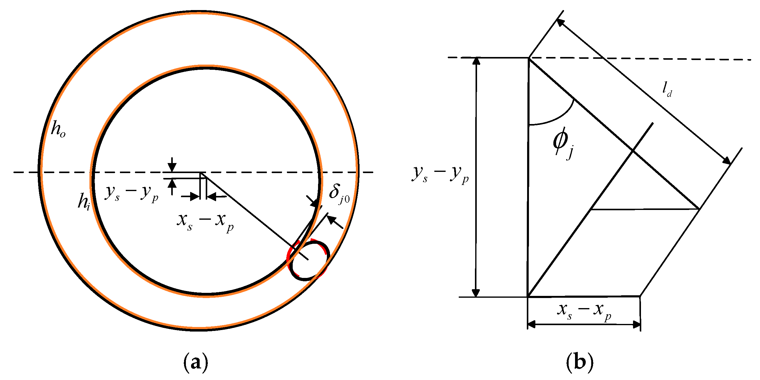
where V denotes the dimensionless speed parameter; M denotes the dimensionless material parameter; W denotes the dimensionless load parameter; R x denotes the equivalent radius of curvature of the two contacting bodies along the rolling direction of the bearing; and κ denotes the contact ellipse parameter. h i represents the central oil-film thickness between the inner ring and the rolling element, and h o represents the central oil-film thickness between the outer ring and the rolling element. f T denotes the oil-film thickness correction factor. Based on Equation (21), the radial contact deformation between the rolling element and the inner/outer rings under point-contact TEHL conditions is compared for the fault-free and faulty states.
The Hertzian contact deformation of the rolling elements under TEHL conditions is shown in Figure 5a, and the radial displacement geometry is presented in Figure 5b, where the orange area represents the oil film.
Based on the geometric relationship shown in Figure 5b, the radial deformation of the first rolling element and the inner/outer rings under fault-free operation can be written as:
δ j 1 = x s x p c o s ϕ j + y s y p s i n ϕ j c h i h o
Secondly, when the outer ring fails, the radial deformation between the first rolling element and the inner and outer rings is converted to the total contact displacement model under point-contact thermo-elastohydrodynamic lubrication:
δ j 0 = x s x p c o s ϕ j + y s y p s i n ϕ j c h i h o β j l d
where l d is the additional displacement.
To determine whether the bearing is in the fault zone, the same switching function β j is introduced as follows:
1     ϕ d < ϕ j < ϕ d + Δ ϕ d 0                        o t h e r w i s e
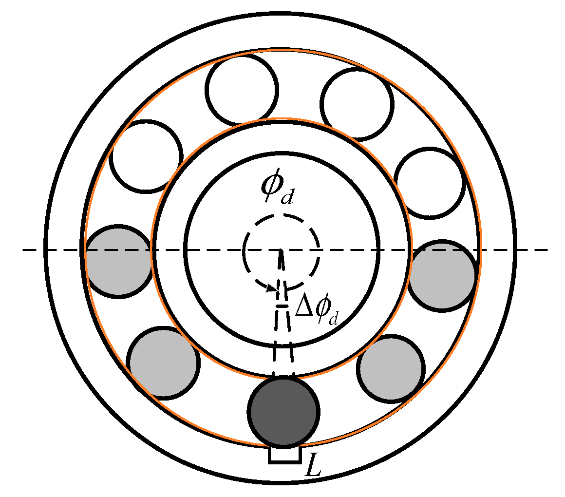
where ϕ d and Δ ϕ d denote the initial angular position and the angular width of the spalled area, respectively. For rolling bearings with outer-ring spalls, assuming the outer ring is fixed and the inner ring rotates, the theoretical time required for a rolling element to traverse this defect zone is denoted by T spall . Based on the geometric relationship, the quantitative mapping between this double-impact time interval and the outer-ring spall size L spall can be explicitly expressed as L spall = 2 r 0 s i n ( ω c T spall / 2 ) , where r 0 is the corresponding radius of the raceway.

3.2. Calculation of Rolling Element–Raceway Contact Force Under TEHL

Under the action of an external radial load, the inner and outer rings undergo radial displacement, inducing contact deformation and corresponding nonlinear contact forces. To calculate these forces under TEHL conditions, the bearing kinematics must first be defined. The angular velocity of the cage (and the rolling elements) is given by ω c = ( 1 D b / D p ) ω s / 2 , where D b and D p are the rolling element and pitch circle diameters, respectively, and ω s is the shaft angular velocity. Consequently, the instantaneous angular position of the j t h rolling element is ϕ j = 2 π ( j 1 ) / n b + ω c d t + ϕ 0 , where n b is the total number of rolling elements, and ϕ 0 is the initial phase.
To integrate the complex TEHL characteristics into the classical dynamic framework efficiently, a quasi-static nonlinear approximation is widely adopted in engineering modeling. Specifically, the improved equivalent stiffness K b is substituted into the classical 3/2 power law to approximate the macroscopic nonlinear contact force F j :
F j = K b δ j 1.5
where K b is the combined stiffness of the improved bearing stiffness and damping model under TEHL, and δ j is the contact deformation of the j-th rolling element.
The nonlinear contact forces of the rolling bearing in the X and Y directions are, respectively:
f x = K b γ j   δ j 3 2   cos ϕ j = K s K p K s + K p γ j δ j 3 2   cos ϕ j
f y = K b γ j   δ j 3 2   sin ϕ j = K s K p K s + K p γ j δ j 3 2 sin ϕ j
The rolling element contributes to the contact force only when it is in the loaded contact region. Therefore, the following switching function is introduced:
γ j = 1     δ j > 0 0     o t h e r w i s e
The Hertzian contact force f x in the horizontal direction of a rolling bearing, for example, varies as follows:
f x = K s K p K s + K p γ j δ j 3 2   c o s ϕ j     n o n f a u l t y   a r e a 0     o t h e r w i s e     f a u l t y   a r e a
The Hertzian contact force f y in the vertical direction of a rolling bearing, for example, varies as follows:
f y = K s K p K s + K p γ j δ j 3 2   s i n ϕ j     n o n f a u l t y   a r e a 0     o t h e r w i s e     f a u l t y   a r e a
Equations (29) and (30) describe the horizontal and vertical components of the rolling element–raceway contact force, respectively. Since the subsequent vibration analysis focuses on the vertical response, the vertical contact-force component f y is used in the following discussion.

3.3. Equation Construction of Rolling-Bearing Dynamics Under TEHL

The 5-DOF dynamic equations used in this section follow the classical bearing/spindle vibration framework reported by Aini et al. [37]. In this framework, the stiffness and damping coefficients associated with the rolling element–raceway contacts are generally treated as prescribed bearing parameters. In the present formulation, the equation structure is retained, while the contact-related terms are parameterized using the equivalent stiffness and damping obtained in Section 2.3. Specifically, the equivalent stiffness and damping include the Hertzian contact stiffness/damping, TEHL-derived oil-film stiffness/damping, and the thermal asymmetry between the inner and outer raceways.
Based on the additional-displacement excitation model and the rolling element–raceway contact-force model under TEHL conditions, these equivalent contact parameters are introduced into the 5-DOF formulation for a rolling bearing with an outer-ring spall defect. Thus, the oil-film pressure, film thickness, and temperature field calculated at the contact interface are transmitted to the system-level dynamic response through the equivalent stiffness/damping, additional-displacement excitation, and nonlinear contact force. The parameters used for the 6205 deep-groove ball bearing are listed in Table 3.
The schematic diagram of the outer-ring spalling defect under TEHL conditions is shown in Figure 6. The dynamic equation for the outer-ring spalling defect of rolling bearings under TEHL is given in Equation (31).
m s x ˙ s + C s x ˙ s + K s x s + f x = 0 m s y ˙ s + C s y ˙ s + K s y s + f y = F r m p x ¨ p + C p x ˙ p + K p x p f x = 0 m p y ¨ p + ( C p + c r ) y ˙ p + ( K p + k r ) y p k r y b c r y ˙ b f y = 0 m r y ¨ b + c r ( y ˙ b y ˙ p ) + k r ( y b y p ) = 0
Equation (31) represents the 5-DOF dynamic formulation used for the outer-ring spall bearing under TEHL conditions. The equation structure follows the classical 5-DOF framework, while the stiffness, damping, and contact-force terms are supplied by the TEHL-based stiffness–damping representation. The formulation includes the motion of the inner race and shaft, the outer race and base, and the unit resonator coupled to the outer-race/base system in the y direction. In this equation, m s is the mass of the inner race and shaft, m p is the mass of the outer race and base, and m r is the mass of the unit resonator. K s and C s are the equivalent stiffness and damping of the inner-race side obtained from the stiffness–damping representation under TEHL conditions, while K p and C p are the corresponding equivalent stiffness and damping of the outer-race side. The parameters k r and c r denote the stiffness and damping of the unit resonator, respectively, and they describe the coupling between the unit resonator displacement y b and the outer-race/base displacement y p . The terms f x and f y are the nonlinear rolling element–raceway contact force components in the x and y directions, respectively, and F r is the radial load applied to the inner race in the y direction. The displacement variables x s and y s denote the motion of the inner race and shaft in the x and y directions, respectively; x p and y p denote the motion of the outer race and base in the x and y directions, respectively; and y b denotes the displacement of the unit resonator in the y direction. The overdot and double overdot denote velocity and acceleration, respectively.

3.4. Simulation and Mechanism Analysis of Rolling-Bearing Impact Characteristics Under TEHL

3.4.1. Vibration Response and Contact Force Analysis for Two Defect Sizes

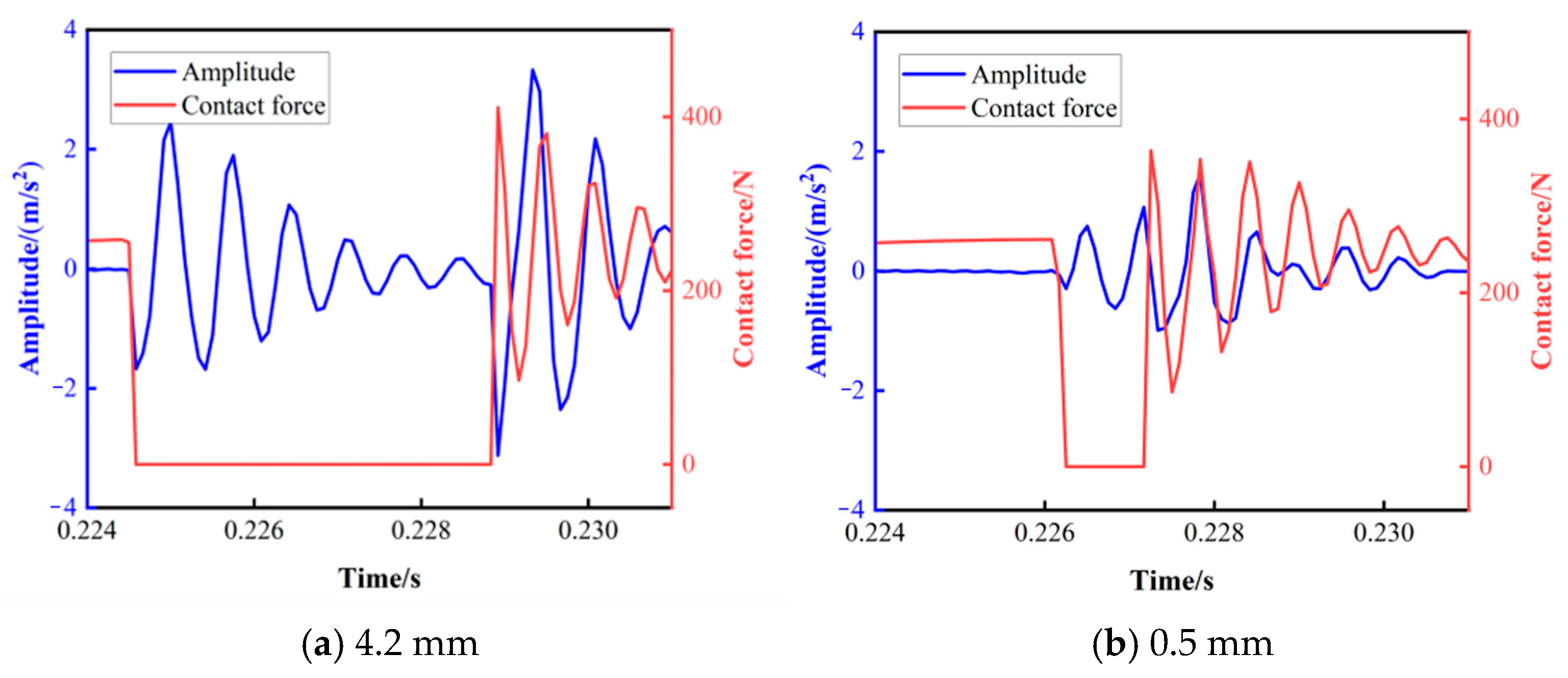
The TEHL-parameterized dynamic formulation is applied to a 6205 deep-groove ball bearing. The simulation conditions are as follows: a sampling frequency of 1.2 kHz, a rotational speed of 1000 rpm, a radial load of 500 N, two representative outer-ring defect widths of 4.2 and 0.5 mm, and a constant defect depth of 1.25 mm. Numerical integration is performed using the fourth-order Runge–Kutta method, and the vibration signals together with the vertical Hertzian contact forces are extracted over 0.224–0.2315 s for comparison. Figure 7a,b show the simulated responses for the large and small defects, respectively. As the defect size decreases, the rolling element enters the defective zone later, consistent with the actual fault evolution characteristics.

3.4.2. Comparison and Mechanism Exploration of Impact Phenomena Associated with Large-Size and Small-Size Failures

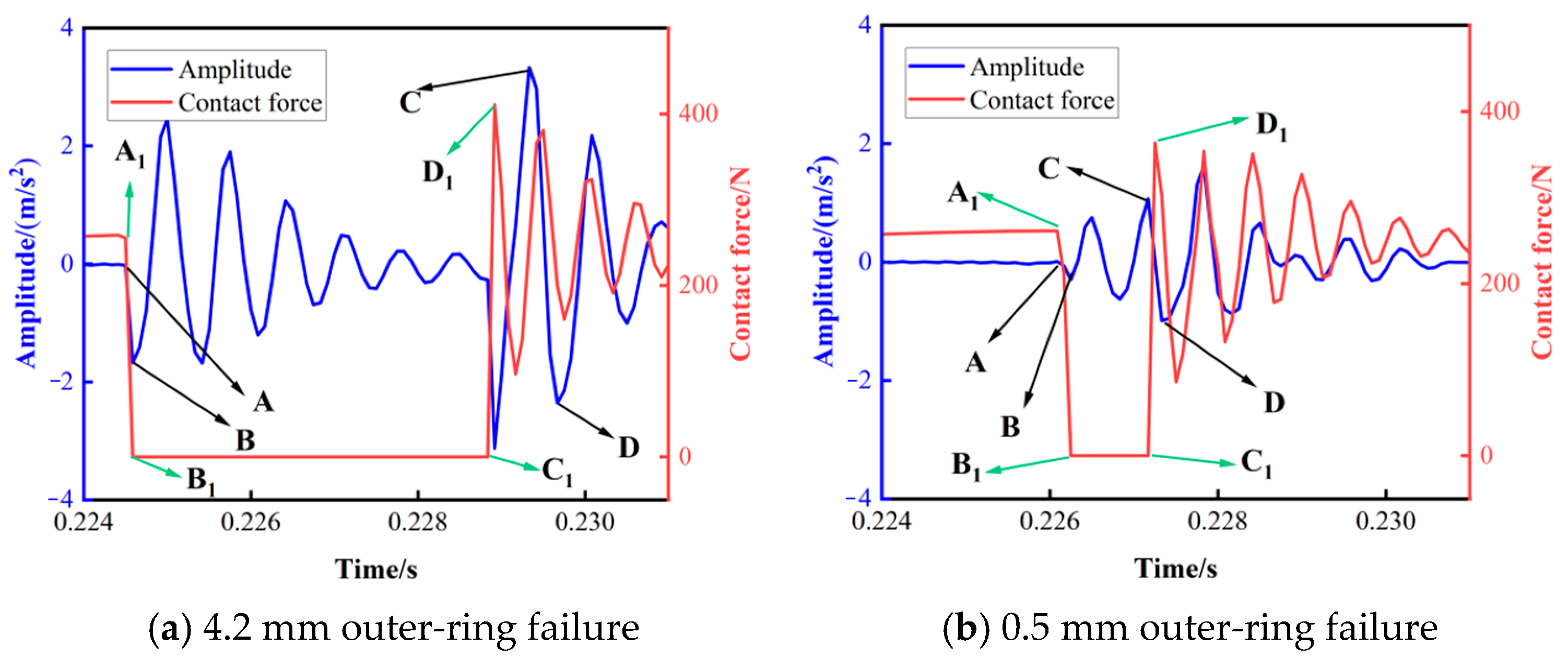
To compare the impact responses predicted by the TEHL-parameterized formulation for different defect sizes, an outer-ring spall with a size of 4.2 mm is defined as a large defect, whereas a 0.5 mm spall is defined as a small defect. The local impact components are magnified in Figure 8, where characteristic points A, B, C, D, A1, B1, C1, and D1 are marked for comparison.
A comparison of Figure 8a,b shows that the 4.2 mm outer-ring spall exhibits a clear double-impact characteristic, whereas the 0.5 mm spall presents only a weak double-impact or single-impact feature. In both cases, points A/A1 correspond to the instant when the rolling element enters the defective zone and triggers the entry impact, while points B/B1 indicate the rapid decay of the contact force to a minimum or zero within the fault region. Points C/C1 denote the instant when the rolling element leaves the defective zone and generates the exit impact. Points D/D1 indicate the subsequent post-exit local response extrema after the rolling element leaves the defective zone. They are used as auxiliary markers to illustrate the post-impact vibration and contact-force evolution, whereas points A and C are used for the subsequent spall-size quantification. For the large defect, the time interval between the entry and exit impacts is sufficiently long, resulting in a distinct double-impact pattern. For the small defect, the two impacts tend to overlap, leading to a weakened double-impact or an apparent single-impact response. Therefore, points A and C are selected as the characteristic instants for subsequent spall-size quantification, and the corresponding contact-force evolution is consistent with the time-domain response predicted by Equation (31).

3.5. Quantitative Diagnosis of Localized Defects Based on the TEHL Model

3.5.1. Dynamic Model Validation and Characteristic Point Analysis at Different Rotational Speeds

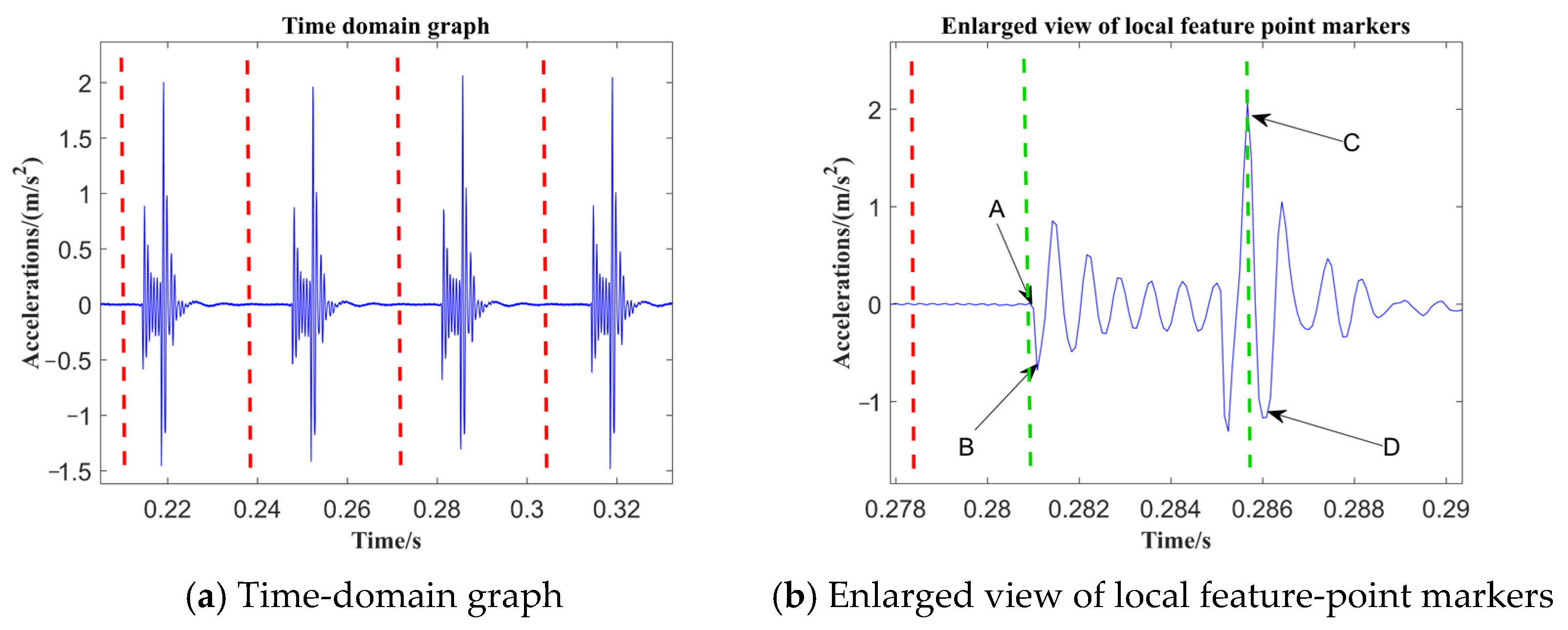
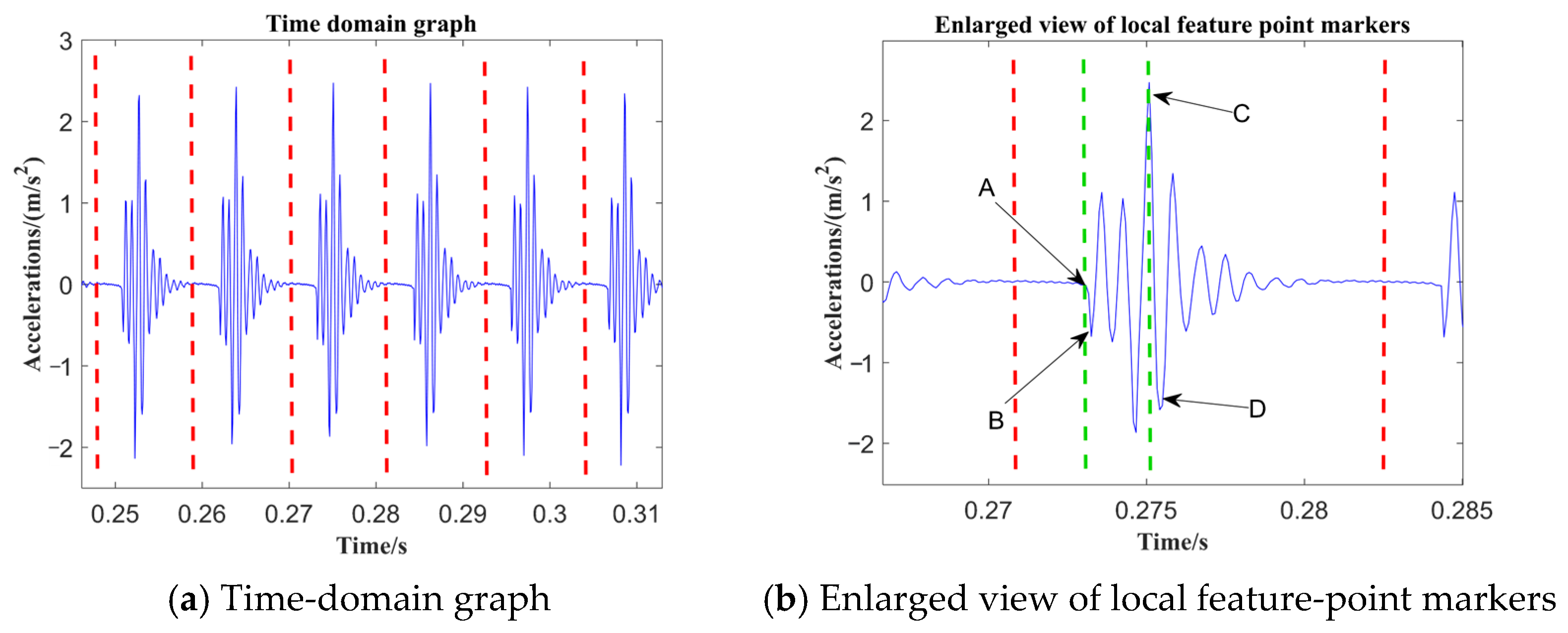
For the quantitative diagnosis of local defects based on the TEHL-parameterized formulation, two rotational speeds (500 rpm, 1500 rpm) were set, along with a radial load of 500 N, an outer-ring spall size of 2 mm, and a sampling frequency of 1.2 kHz. Time-domain diagrams of the TEHL-parameterized formulation and enlarged views of the local feature-point markers are presented in Figure 9 and Figure 10.
As shown in Figure 9a and Figure 10a, the simulated impact responses exhibit periodic features corresponding to repeated rolling-element passages over the outer-ring spall. This periodic behavior is consistent with the expected defect-passing mechanism and supports the dynamic consistency of the TEHL-parameterized formulation.
In Figure 9b and Figure 10b, the local responses are enlarged to facilitate characteristic-point identification. Points A and C are identified as the entry-impact and exit-impact instants, denoted by ( t A ) and ( t C ), respectively. Points B and D denote the adjacent local response extrema following the entry and exit impacts, respectively. They are used as auxiliary markers to illustrate the local oscillatory response around the two impacts, whereas only points A and C are used to determine the double-impact interval ( t C t A ) for the subsequent spall-size calculation. The green dotted lines mark the identified entry- and exit-impact instants, while the red dotted lines indicate the selected fault-passing period or localized time window. As the rotational speed increases, the interval ( t C t A ) decreases, which is consistent with the shorter time required for the rolling element to pass through the spalled region. The outer-ring spall size is then calculated using the double-impact time-interval quantification formula derived from the TEHL-parameterized formulation:
L spall = 2 r 0 s i n ω c t C t A 2
where L spall is the outer-ring spall length, r 0 denotes the radius corresponding to the outer-raceway spall trajectory, ω c is the cage angular velocity, and t A and t C are the entry-impact and exit-impact instants identified from the double-impact response, respectively.

3.5.2. Comparative Analysis of Spall-Size Estimation Accuracy Using Different Dynamic Formulations

To verify the accuracy of the proposed quantitative rolling-bearing fault diagnosis method based on point-contact TEHL, the 5-DOF formulation with TEHL-based stiffness–damping parameters is compared with conventional 5-DOF, 4-DOF, and 2-DOF dynamic models. Quantitative calculations are performed for six spall sizes (0.2, 0.6, 1.2, 2.0, 3.0, and 4.2 mm) at a rotational speed of 1000 rpm. The corresponding error comparison results are presented in Table 4.
As shown in Table 4, the 5-DOF formulation with the TEHL-based stiffness–damping representation gives the closest estimates to the reference spall sizes among the compared models. For the six spall sizes of 0.2, 0.6, 1.2, 2.0, 3.0, and 4.2 mm, the relative errors are 6.00%, 5.33%, 3.50%, 2.05%, 1.33%, and 0.60%, respectively. This significant improvement in quantitative diagnostic accuracy is fundamentally attributed to the physical nature of the TEHL oil film. In conventional dry-contact models, the double-impact time interval is determined solely by the rigid defect geometry and solid kinematics. In contrast, the proposed model reveals that the oil film essentially acts as an additional dynamic clearance and a damping buffer. As the rolling element enters and exits the spall, the load-dependent variation in oil-film thickness alters the actual spatial trajectory of the rolling element. Concurrently, oil-film damping induces a subtle phase delay in the transient impact force peaks (e.g., characteristic points A and C). Consequently, incorporating these TEHL characteristics provides a more physically meaningful time-interval mapping for spall-size evaluation, thereby reducing the estimation deviation associated with purely elastic contact models.

4. Experimental Validation

4.1. Experimental Equipment and Bearing Failure Parts

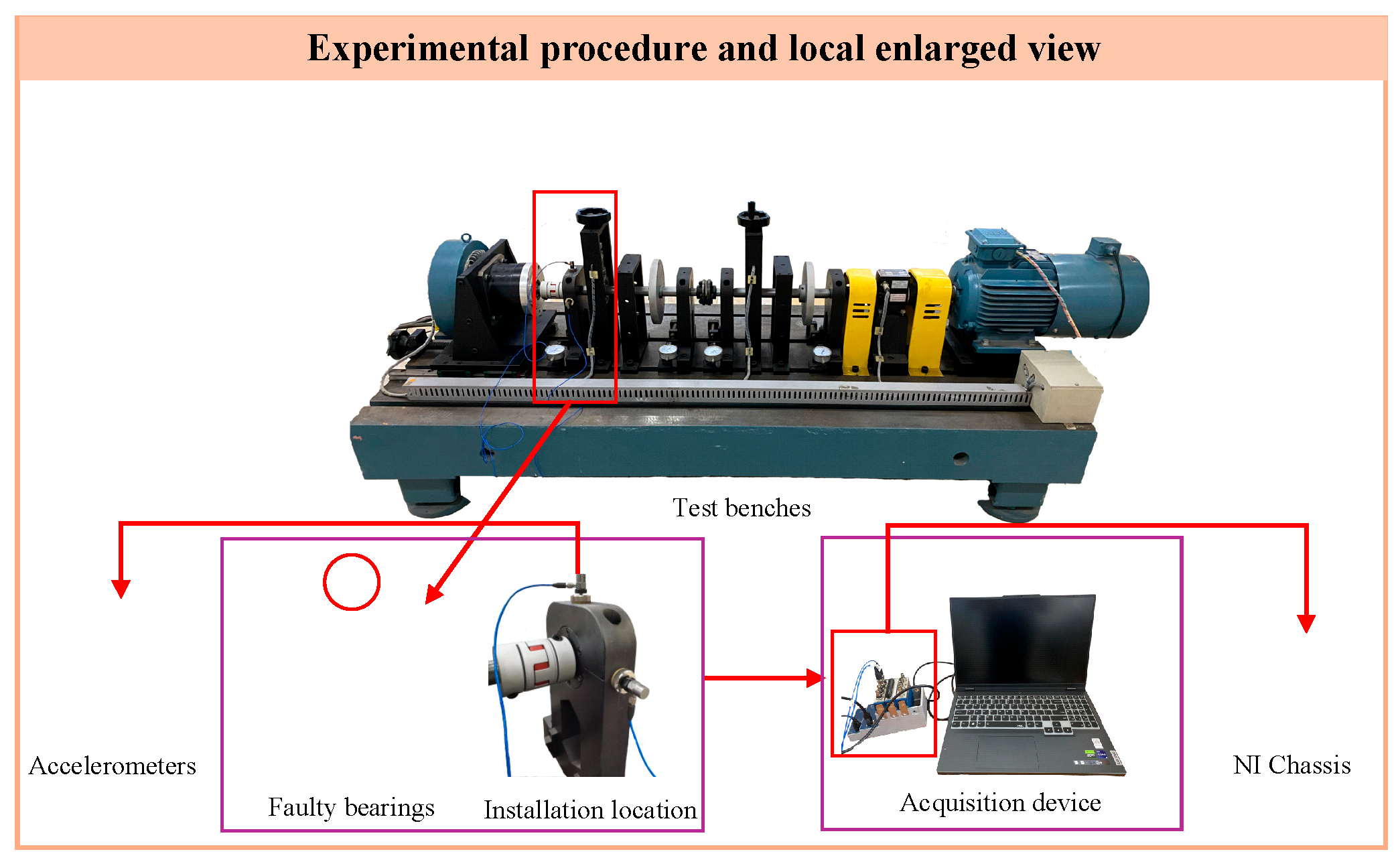
To validate the accuracy of the proposed TEHL-based quantitative diagnosis method, artificial bearing faults were introduced using the HZXT-DS-003 (DongHua Testing Technology Co., Ltd., Jingjiang, China) double-span, double-rotor rolling-bearing test rig, as shown in Figure 11. The test bench mainly comprises a bearing housing, a radial loader, a tachometer-torque meter, and a motor. Its drive system includes a 7.5 kW variable-frequency motor (speed range: 0–3000 r/min) and a 380 V, 10 kW vector-controlled three-phase inverter. The tested rolling bearing model is 6205-2-RS, and a 1.2 kHz sampling frequency was used for the vibration signal.
In the comparison between experimental and simulated responses, vibration signals from the bearing with a 0.6 mm outer-ring spall were selected and compared with the simulated signals generated by the TEHL-parameterized formulation.

4.2. Comparative Analysis of Experimental and Modeled Fault Characteristic Frequencies for an Outer-Ring Defect of 0.6 mm

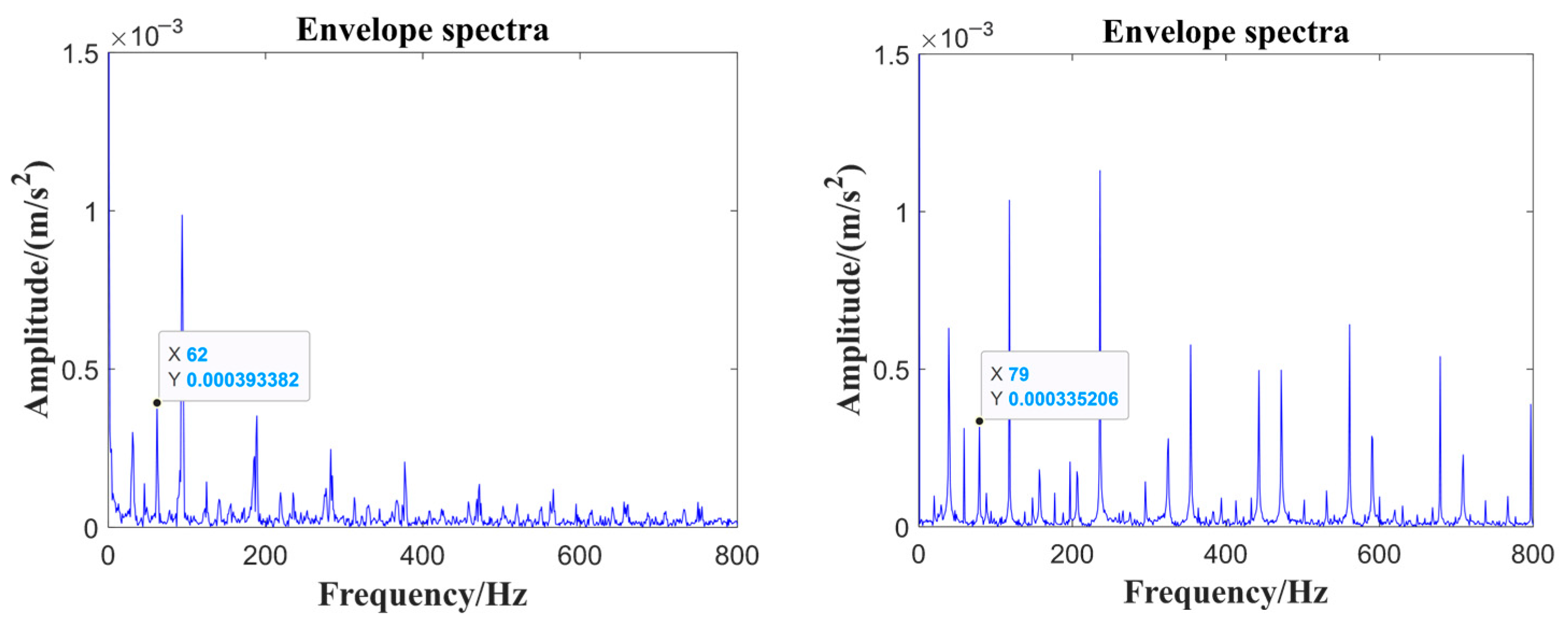
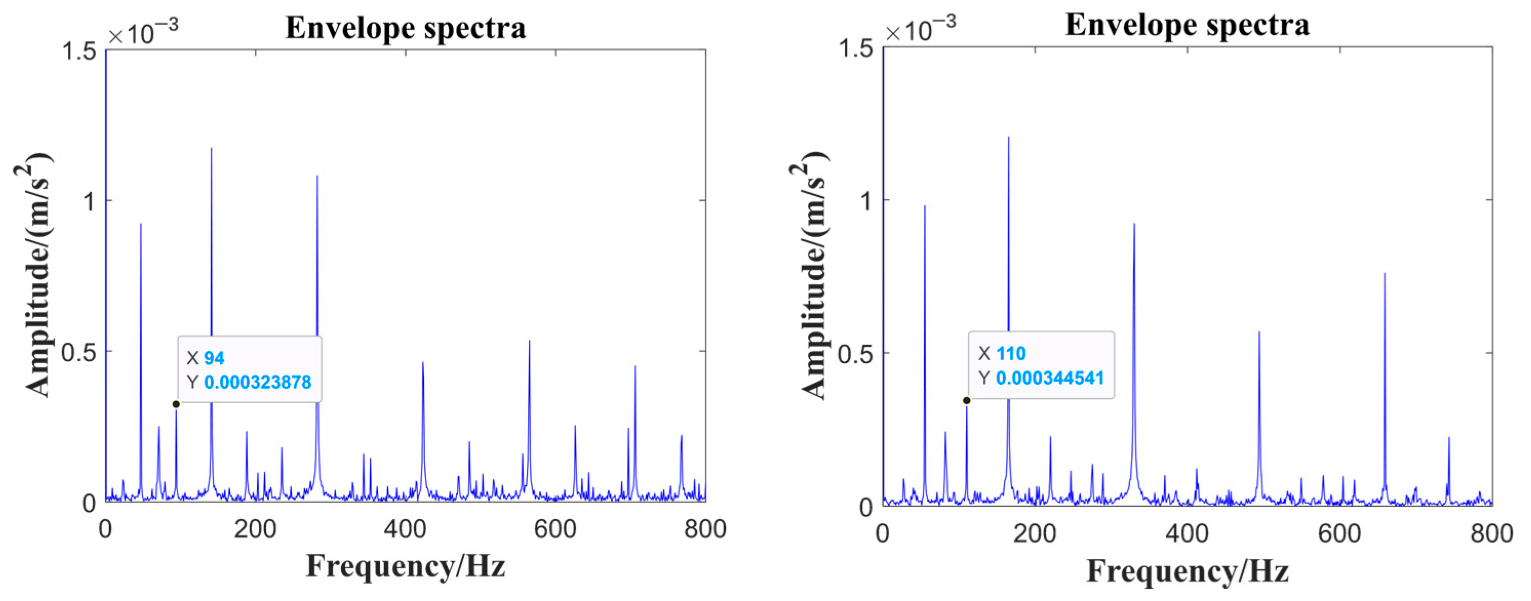
A radial load of 500 N, a sampling frequency of 1.2 kHz, a rotational speed series of 1000, 1250, 1500 and 1750 rpm, and an outer-ring spalling width of 0.6 mm were configured for bearing fault experimental signal analysis. The corresponding results are illustrated in Figure 12 and Figure 13, followed by a comparison of the theoretical, simulated, and experimental outer-ring fault characteristic frequencies under the four rotational speeds.
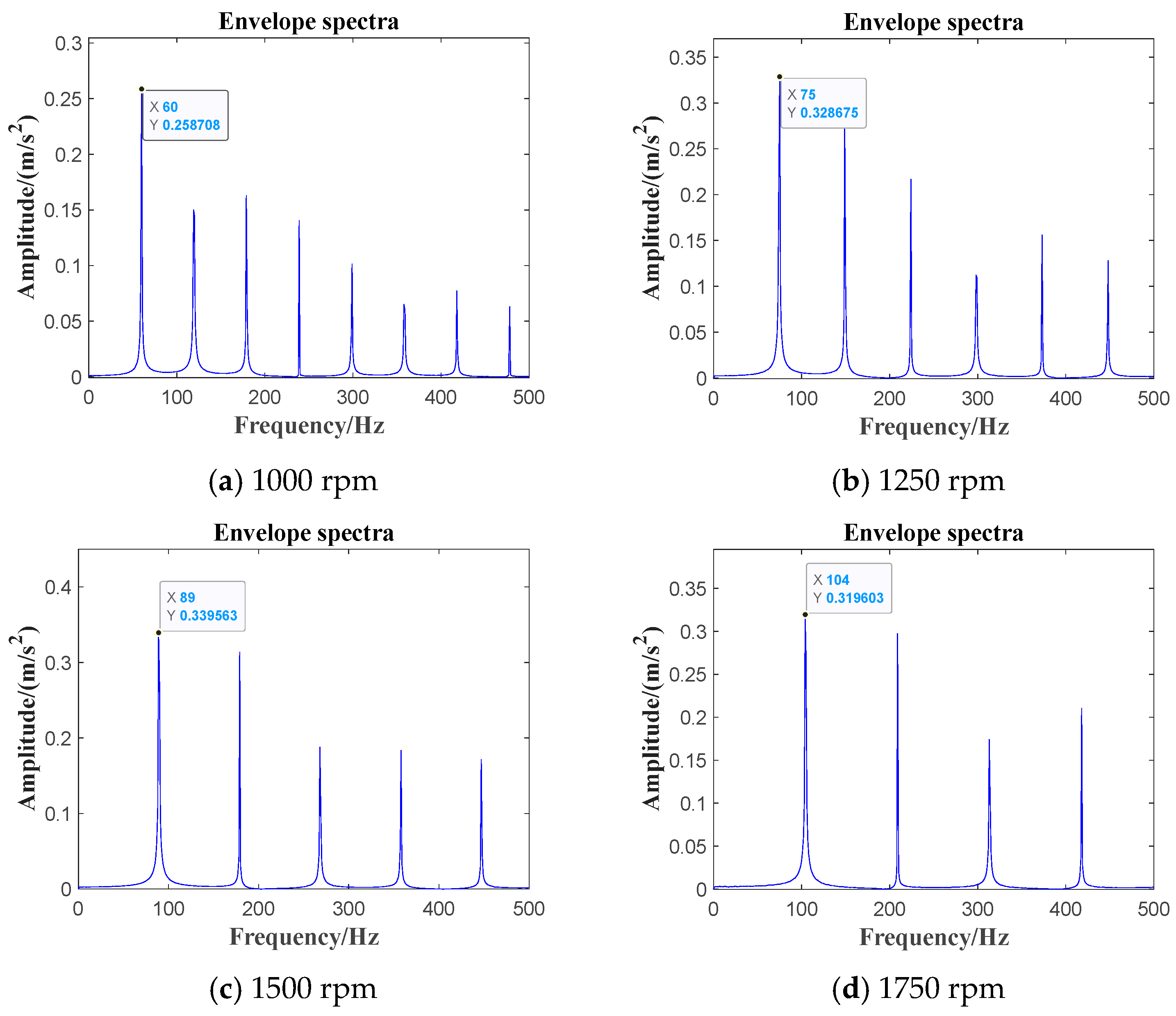
Figure 14 presents the envelope spectra of the outer-ring fault with a 0.6 mm spall obtained from the dynamic model at four rotational speeds: 1000, 1250, 1500, and 1750 rpm.
Based on the above results, the theoretical, simulated, and experimental outer-ring fault characteristic frequencies at different rotational speeds are compared in Table 5.
Through the comparative analysis of the 0.6 mm outer-ring fault eigenfrequency at four different rotational speeds of 1000 rpm, 1250 rpm, 1500 rpm and 1750 rpm in Table 5 for the theoretical, simulated, and experimental values, it can be seen that the simulation and theoretical error are within 0.78%, and the maximum error between the simulated and experimental values is 5.45%.

4.3. Quantitative Comparative Analysis of Experimental and Modeled Double Impacts with Outer-Ring Defect of 0.6 mm

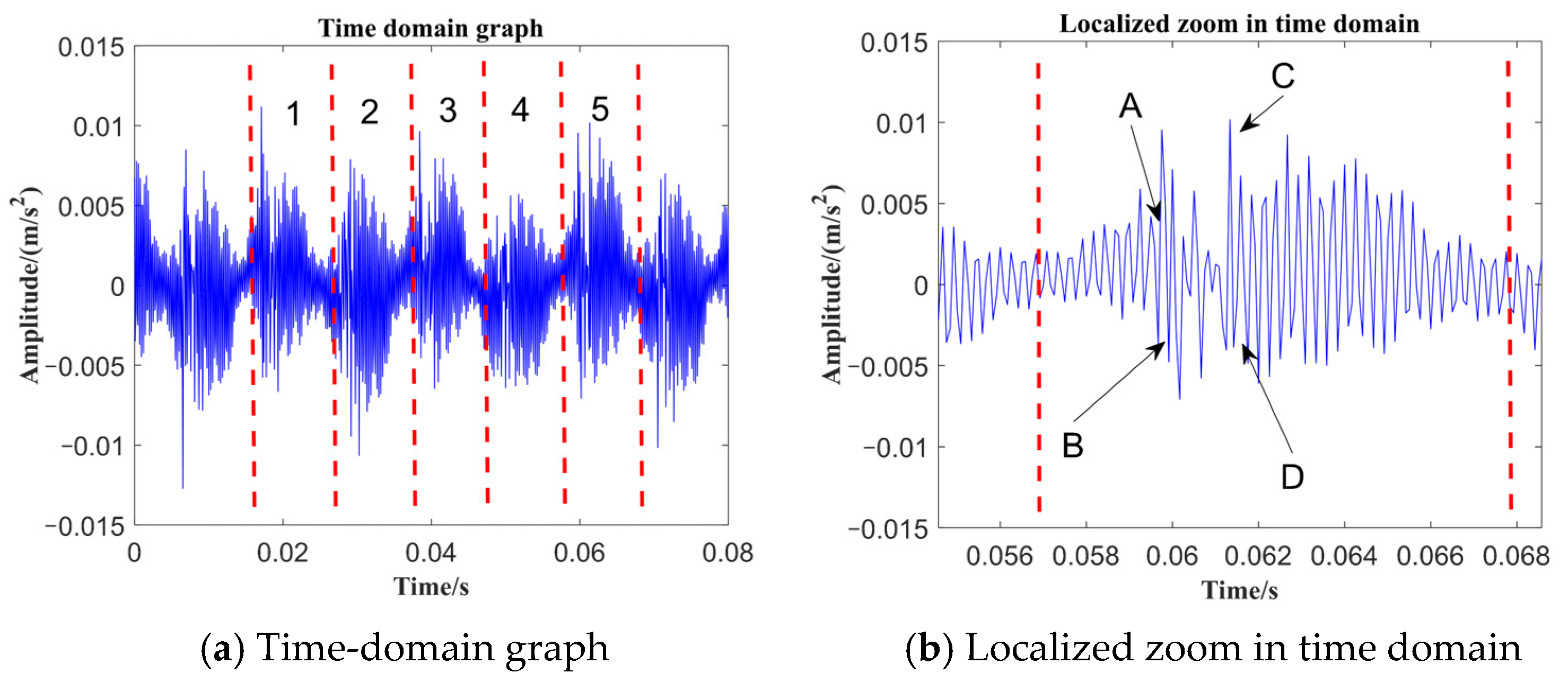
In the quantitative comparative analysis of the experimental and model signals for the outer-ring spalling defect of 0.6 mm, the 1000 rpm experimental signal is selected for the double-shock quantitative analysis study. Figure 15 depicts the time-domain waveform of the experimental signal for the outer ring with a 0.6 mm fault under 1000 rpm operating condition, along with its localized time-domain magnification.
The time-domain waveform in Figure 15a shows periodic impact responses for the bearing with a 0.6 mm outer-ring spall. The red dotted lines delimit five successive impact periods, which are labeled as 1–5. After the signal is divided into five periods, the fifth period is selected for local enlargement and characteristic-point identification, as shown in Figure 15b. In Figure 15b, points A and C are identified as the entry-impact and exit-impact instants, respectively, while points B and D denote adjacent local extrema used as auxiliary markers for double-impact identification. The double-impact time-interval quantification method based on the TEHL-parameterized formulation is then applied to estimate the outer-ring spall size. The estimated value is compared with the reference spall size of 0.6 mm, and the results are summarized in Table 6.
As shown in Table 6, the spall size estimated by the TEHL-based quantitative diagnosis method is 0.665 mm, whereas the reference outer-ring spall size is 0.6 mm. The absolute error is 0.065 mm, corresponding to a relative error of 10.83%. This result shows that the estimated spall size is in reasonable agreement with the reference defect size under the tested conditions, supporting the applicability of the proposed TEHL-based quantitative diagnosis method for outer-ring spall-size estimation.

5. Conclusions

This paper proposes a quantitative diagnosis method for rolling bearings with outer-ring spalls. By establishing a physical transfer path from the local lubricated interface to the macroscopic double-impact response, this study bridges the gap between tribodynamics and spall-size estimation. The main conclusions are as follows:
  • A novel equivalent stiffness–damping representation is formulated to characterize the point-contact TEHL interface. Unlike conventional idealized Hertzian assumptions, this approach explicitly parameterizes the temperature-dependent oil-film pressure, film thickness, and inner–outer raceway thermal asymmetry, providing a rigorous tribological boundary for localized-defect modeling.
  • The physical mechanism of the lubricated double-impact response is elucidated by integrating the TEHL-derived representation into a classical 5-DOF framework. The model reveals that the oil film essentially acts as an additional dynamic clearance and damping buffer. This mechanism alters the spatial trajectory of rolling elements traversing the spall and induces phase delays in impact force peaks, thereby affecting the double-impact time interval.
  • The proposed method significantly improves the accuracy of spall-size quantification under thermally coupled conditions. Comparative analyses and experimental validation demonstrate that the TEHL-parameterized formulation restricts the frequency estimation error to within 5.45% and achieves a spall-size prediction error of 10.83% in experiments. Furthermore, it explicitly outperforms conventional 5-DOF, 4-DOF, and 2-DOF dry-contact models across all defect sizes (with theoretical errors reduced to below 6.00%), validating its reliability for high-precision fault diagnosis.

Author Contributions

W.J.: conceptualization, methodology, writing—original draft preparation. C.L.: investigation, data curation. T.L.: investigation, validation. J.H.: formal analysis, visualization. C.Z. (Chengshi Zhang): software, formal analysis. F.J.: resources, validation. F.Z.: methodology, supervision. C.Z. (Chao Zhang): project administration, funding acquisition, writing—review and editing. All authors have read and agreed to the published version of the manuscript.

Funding

This research was funded by the National Natural Science Foundation of China, grant number 52305115; the Natural Science Foundation of the Inner Mongolia Autonomous Region, grant number 2023QN05031; the Inner Mongolia Autonomous Region Science and Technology Special Project, grant number 2024SKYPT0032; the Science and Technology Support Project for the Construction of the National Sustainable Development Agenda Innovation Demonstration Zone, grant number KCX2024010; the Baotou Municipal Science and Technology Program, grant number 2025C1001; and the Inner Mongolia Autonomous Region Key R&D and Technology Transfer Special Project, grant number 2025KJHZ0033. The authors also thank the State Key Laboratory of Tribology at Tsinghua University for providing experimental facilities and technical guidance.

Data Availability Statement

Due to laboratory regulations, the method of obtaining experimental data is temporarily unavailable.

Conflicts of Interest

The authors declare that they have no known competing financial interests or personal relationships that could have appeared to influence the work reported in this manuscript. All authors confirm that the research was conducted in accordance with ethical standards and that no conflicts of interest exist. The funding sources for this study are acknowledged in the Acknowledgments section, and they did not influence the design, execution, or interpretation of the research.

References

  1. Zhang, C.; Liu, T.; Wang, Y.; He, H.; Zhang, C. Mechanism Study of Symmetric Mechanism-Rolling Bearing Dynamic System Considering the Influence of Temperature Factor. Symmetry 2023, 15, 2166. [Google Scholar] [CrossRef]
  2. Rahnejat, H.; Gohar, R. The Vibrations of Radial Ball Bearings. Proc. Inst. Mech. Eng. Part C J. Mech. Eng. Sci. 1985, 199, 181–193. [Google Scholar] [CrossRef]
  3. Wijnant, Y.H.; Wensing, J.A.; van Nijen, G.C. The Influence of Lubrication on the Dynamic Behaviour of Ball Bearings. J. Sound Vib. 1999, 222, 579–596. [Google Scholar] [CrossRef]
  4. Sarangi, M.; Majumdar, B.C.; Sekhar, A.S. On the Dynamics of Elastohydrodynamic Mixed Lubricated Ball Bearings. Part I: Formulation of Stiffness and Damping Coefficients. Proc. Inst. Mech. Eng. Part J J. Eng. Tribol. 2005, 219, 411–421. [Google Scholar] [CrossRef]
  5. Mohammadpour, M.; Johns-Rahnejat, P.M.; Rahnejat, H. Roller Bearing Dynamics under Transient Thermal-Mixed Non-Newtonian Elastohydrodynamic Regime of Lubrication. Proc. Inst. Mech. Eng. Part K J. Multi-Body Dyn. 2015, 229, 407–423. [Google Scholar] [CrossRef]
  6. Zhang, Y.Y.; Wang, X.L.; Yan, X.L. Dynamic Behaviors of the Elastohydrodynamic Lubricated Contact for Rolling Bearings. J. Tribol. 2013, 135, 021501. [Google Scholar] [CrossRef]
  7. Luo, M.; Guo, Y.; André, H.; Wu, X.; Na, J. Dynamic Modeling and Quantitative Diagnosis for Dual-Impulse Behavior of Rolling Element Bearing with a Spall on Inner Race. Mech. Syst. Signal Process. 2021, 158, 107711. [Google Scholar] [CrossRef]
  8. Gomez, J.L.; Bourdon, A.; André, H.; Rémond, D. Modelling Deep Groove Ball Bearing Localized Defects Inducing Instantaneous Angular Speed Variations. Tribol. Int. 2016, 98, 270–281. [Google Scholar] [CrossRef]
  9. Jiang, Y.; Huang, W.; Luo, J.; Wang, W. An Improved Dynamic Model of Defective Bearings Considering the Three-Dimensional Geometric Relationship between the Rolling Element and Defect Area. Mech. Syst. Signal Process. 2019, 129, 694–716. [Google Scholar] [CrossRef]
  10. Yan, P.; Yan, C.; Wang, K.; Wang, F.; Wu, L. 5-DOF Dynamic Modeling of Rolling Bearing with Local Defect Considering Comprehensive Stiffness under Isothermal Elastohydrodynamic Lubrication. Shock Vib. 2020, 2020, 9310278. [Google Scholar] [CrossRef]
  11. Tian, J.; Zhang, C.; Liang, H.; Guo, D. Simulation of the Load Reduction Process of High-Speed Angular Contact Ball Bearing with Coupling Model of Dynamics and Thermo-Elastohydrodynamic Lubrication. Tribol. Int. 2022, 165, 107292. [Google Scholar] [CrossRef]
  12. Wang, Y.; Yan, C.; Lu, Z.; Liu, Y.; Wu, L. Effect of Thermal Elastohydrodynamic Lubrication on Vibration Characteristics of Ball Bearing with Local Defect. Proc. Inst. Mech. Eng. Part K J. Multi-Body Dyn. 2022, 236, 488–500. [Google Scholar] [CrossRef]
  13. Tian, Y.; Yan, C.; Liu, Y.; Kang, J.; Lu, Z.; Wu, L. Dynamic Modelling of Deep Groove Ball Bearings with Different Local Defects Considering Skidding and Thermal Elastohydrodynamic Lubrication. Proc. Inst. Mech. Eng. Part K J. Multi-Body Dyn. 2023, 237, 511–533. [Google Scholar] [CrossRef]
  14. Huo, Z.; Chen, J.; Hao, L.; Gao, J. Study on the Effect of Starved Lubrication on the Dynamic Characteristics of Locally Failed Roller Bearings. Tribol. Trans. 2024, 67, 952–961. [Google Scholar] [CrossRef]
  15. Bai, X.; Zou, R.; Shi, H.; Zheng, H. Influence of Lubrication State Transition on Dynamic Characteristics of Deep Groove Ball Bearing with Localized Defect in Thermal Environment. Int. J. Non-Linear Mech. 2024, 167, 104879. [Google Scholar] [CrossRef]
  16. Huo, Z.; Chen, J.; Hao, L.; Gao, J. Dynamic Investigation of Deep Groove Ball Bearings with Localised Failure of Outer Ring Considering the Effect of Starved Lubrication. Lubr. Sci. 2025, 37, 315–327. [Google Scholar] [CrossRef]
  17. Peng, C.; Wei, J.; Liu, K.; Cao, H. Dynamic Characteristics of Angular Contact Ball Bearings with Mild Defect on Outer Raceway. Eng. Fail. Anal. 2025, 178, 109721. [Google Scholar] [CrossRef]
  18. Epps, I.K. An Investigation into Vibrations Excited by Discrete Faults in Rolling Element Bearings. Ph.D. Thesis, University of Canterbury, Christchurch, New Zealand, 1991. Available online: https://ir.canterbury.ac.nz/handle/10092/6025 (accessed on 24 June 2026).
  19. Randall, R.B.; Sawalhi, N. Signal Processing Tools for Tracking the Size of a Spall in a Rolling Element Bearing. In IUTAM Symposium on Emerging Trends in Rotor Dynamics; IUTAM Bookseries; Gupta, K., Ed.; Springer: Dordrecht, The Netherlands, 2011; Volume 25, pp. 429–440. [Google Scholar] [CrossRef]
  20. Sawalhi, N.; Randall, R.B. Vibration Response of Spalled Rolling Element Bearings: Observations, Simulations and Signal Processing Techniques to Track the Spall Size. Mech. Syst. Signal Process. 2011, 25, 846–870. [Google Scholar] [CrossRef]
  21. Ming, A.B.; Zhang, W.; Qin, Z.Y.; Chu, F.L. Dual-Impulse Response Model for the Acoustic Emission Produced by a Spall and the Size Evaluation in Rolling Element Bearings. IEEE Trans. Ind. Electron. 2015, 62, 6606–6615. [Google Scholar] [CrossRef]
  22. Singh, M.; Kumar, R. Thrust Bearing Groove Race Defect Measurement by Wavelet Decomposition of Pre-Processed Vibration Signal. Measurement 2013, 46, 3508–3515. [Google Scholar] [CrossRef]
  23. Jena, D.P.; Panigrahi, S.N. Precise Measurement of Defect Width in Tapered Roller Bearing Using Vibration Signal. Measurement 2014, 55, 39–50. [Google Scholar] [CrossRef]
  24. He, S.; Zhu, L.; Li, H.; Hu, C.; Bao, J. Cross-Condition Quantitative Diagnosis Method for Bearing Faults Based on IDRSN-ECDAN. Meas. Sci. Technol. 2024, 35, 025129. [Google Scholar] [CrossRef]
  25. Wu, R.; Wang, X.; Ni, Z.; Zeng, C. Dual-Impulse Behavior Analysis and Quantitative Diagnosis of the Raceway Fault of Rolling Bearing. Mech. Syst. Signal Process. 2022, 169, 108734. [Google Scholar] [CrossRef]
  26. Luo, M.; Guo, Y.; Su, Z.; André, H.; Tang, Z.; Zhou, C.; Li, C. Defect Quantification Evaluation of a Rolling Element Bearing Based on Physical Modelling and Instantaneous Vibration Energy Investigation. J. Sound Vib. 2025, 600, 118875. [Google Scholar] [CrossRef]
  27. Roelands, C.J.A.; Winer, W.O.; Wright, W.A. Correlational Aspects of the Viscosity–Temperature–Pressure Relationship of Lubricating Oils. J. Lubr. Technol. 1971, 93, 209–210. [Google Scholar] [CrossRef]
  28. Houpert, L. New Results of Traction Force Calculations in Elastohydrodynamic Contacts. J. Tribol. 1985, 107, 241–245. [Google Scholar] [CrossRef]
  29. Dowson, D.; Higginson, G.R. Elastohydrodynamic Lubrication; Pergamon Press: Oxford, UK, 1966. [Google Scholar]
  30. Johnson, K.L. Contact Mechanics; Cambridge University Press: Cambridge, UK, 1985. [Google Scholar] [CrossRef]
  31. Cheng, H.S. A Refined Solution to the Thermal-Elastohydrodynamic Lubrication of Rolling and Sliding Cylinders. ASLE Trans. 1965, 8, 397–410. [Google Scholar] [CrossRef]
  32. Jaeger, J.C. Moving Sources of Heat and the Temperature at Sliding Contacts. J. Proc. R. Soc. N. S. W. 1943, 76, 203–224. [Google Scholar] [CrossRef]
  33. Hertz, H. Ueber die Berührung fester elastischer Körper. J. Reine Angew. Math. 1882, 92, 156–171. [Google Scholar] [CrossRef]
  34. Harris, T.A.; Kotzalas, M.N. Essential Concepts of Bearing Technology, 5th ed.; CRC Press: Boca Raton, FL, USA, 2006. [Google Scholar] [CrossRef]
  35. Genta, G. On a Persistent Misunderstanding of the Role of Hysteretic Damping in Rotor Dynamics. J. Vib. Acoust. 2004, 126, 459–461. [Google Scholar] [CrossRef]
  36. Hamrock, B.J.; Dowson, D. Elastohydrodynamic Lubrication of Elliptical Contacts for Materials of Low Elastic Modulus I—Fully Flooded Conjunction. J. Lubr. Technol. 1978, 100, 236–245. [Google Scholar] [CrossRef]
  37. Aini, R.; Rahnejat, H.; Gohar, R. A Five Degrees of Freedom Analysis of Vibrations in Precision Spindles. Int. J. Mach. Tools Manuf. 1990, 30, 1–8. [Google Scholar] [CrossRef]
Figure 1. Summary of stiffness and damping characteristics of SKF 6205 bearing under different modeling conditions: (a) Simplified stiffness–damping model without bearing inner- and outer-ring oil-film stiffness and structural damping under TEHL conditions; (b) Simplified stiffness–damping model with bearing inner- and outer-ring oil-film stiffness and structural.
Lubricants 14 00261 g001
Figure 2. Schematic diagrams for the point-contact TEHL model: (a) point-contact solution domain; (b) equivalent elastic deformation model; (c) theoretical distribution of oil-film shape and elastohydrodynamic pressure.
Lubricants 14 00261 g002
Figure 3. Numerical results of the point-contact TEHL model.
Lubricants 14 00261 g003
Figure 4. Simplified stiffness–damping representation of the rolling element–raceway contact under TEHL conditions.
Lubricants 14 00261 g004
Figure 5. Contact deformation and radial displacement relationship of the rolling element–raceway contact under TEHL conditions: (a) Hertzian contact deformation of the rolling element; (b) geometric relationship of radial displacement, where the orange region denotes the lubricating oil film.
Lubricants 14 00261 g005
Figure 6. Schematic diagram of an outer-ring failure in a rolling element.
Lubricants 14 00261 g006
Figure 7. Simulated signals versus Hertzian contact force variation for rolling-bearing defects of different sizes.
Lubricants 14 00261 g007
Figure 8. Localized enlargement of rolling-bearing outer-ring fault signals.
Lubricants 14 00261 g008
Figure 9. Time-domain response of a 2 mm outer-ring fault at 500 rpm, obtained from the TEHL-parameterized formulation with local feature-point markers.
Lubricants 14 00261 g009
Figure 10. Simulated time-domain response plot at 1500 rpm for a 2 mm outer ring, with the local feature-point markers zoomed in.
Lubricants 14 00261 g010
Figure 11. Experimental flow and local zoom-in diagram. The red circle indicates the localized outer-ring spall on the faulty bearing.
Lubricants 14 00261 g011
Figure 12. Experimental signals and envelope spectra for 1000 rpm and 1250 rpm outer-ring faults with a 0.6 mm spall.
Lubricants 14 00261 g012
Figure 13. Signal envelope spectra for 1500 rpm and 1750 rpm outer-ring fault experiments with a 0.6 mm spall.
Lubricants 14 00261 g013
Figure 14. Envelope spectra of the simulated signals of 0.6 mm defects at 1000 rpm, 1250 rpm, 1500 rpm, 1750 rpm.
Lubricants 14 00261 g014
Figure 15. Time-domain plot of the experimental signal with time-domain local magnification for the 1000 rpm outer ring 0.6 mm fault.
Lubricants 14 00261 g015
Table 1. Geometric parameters of the 6205 deep-groove ball bearing.
Parameter NameValue
Number of rolling elements N b
Diameter of rolling element D b / ( m m )
9
7.938
Pitch circle diameter D p / ( m m ) 38.5
Inner raceway diameter D i / ( m m ) 30.562
Outer raceway diameter D o / (mm)46.438
Radial internal clearance c / ( μ m ) 3
Contact angle α / ( ° ) 0
Table 2. Parameters of No. 4106 aviation lubricating oil.
Parameter Name and UnitValue
Thermal Conductivity k h / ( W / ( m K ) ) 0.0966
Viscosity–Pressure Coefficient α / ( Pa 1 ) 1.85 × 10⁻⁸
Viscosity–Temperature Coefficient β / ( K 1 ) 0.0315
Specific Heat Capacity c h / ( J / ( kg K ) ) 2000
Ambient Temperature T 0 / ( K ) 298.15
Initial Viscosity η 0 / ( Pa s ) 0.055
Initial Density ρ 0 / ( kg / m 3 ) 890
Table 3. Parameters used in the TEHL-based 5-DOF dynamic model of the 6205 deep-groove ball bearing.
Parameter NameValue and UnitParameter NameValue and Unit
Inner race and shaft mass m s
Outer race and shaft stiffness K s
1.2638 kg
4.241 × 10⁴ N/m
Unit resonator mass m r
Unit resonator stiffness k r
1 kg
8.8826 × 10⁹ N/m
Inner race and shaft damping C s 2376.8 N s/mUnit resonator damping c r 9424.8 N s/m
Outer race and base mass m p 12.638 kgOuter race and base stiffness K p 15.1056 × 10⁶ N/m
Outer race and base damping C p 2210.7 N s/mContact stiffness K d 1.8918 × 10¹⁰ N/m
Table 4. Quantitative comparison of spall-size estimates obtained using different dynamic formulations.
Reference Spall Size (mm)TEHL-Parameterized 5-DOF Formulation (mm)Conventional 5-DOF Model (mm)Conventional 4-DOF Model (mm)Conventional 2-DOF Model (mm)
0.20.2120.2350.2510.188
0.60.6320.6480.6710.495
1.21.2421.2911.3980.925
2.02.0412.0962.2351.734
3.03.0403.0933.2042.758
4.24.2254.2964.3823.951
Table 5. Comparison of theoretical, simulated, and experimental outer-ring fault eigenfrequencies at different rotational speeds for 0.6 mm outer-ring faults.
Outer-Ring Failure Characteristic Frequency and ErrorRotation Speed (r/min)
1000125015001750
Theoretical value (Hz)59.5474.4289.30104.19
Simulation value (Hz)607589104
Experimental value (Hz)627994110
Simulation and theoretical errors (%)0.770.780.340.18
Simulation and experimental errors (%)3.235.065.325.45
Table 6. Comparison between the reference 0.6 mm outer-ring spall size and the estimated spall size.
Parameter NameNumerical Values and Units
Reference outer-ring spall size
Estimated spall size by the TEHL-based method
0.6 mm
0.665 mm
Absolute error0.065 mm
Relative error10.83%
Disclaimer/Publisher’s Note: The statements, opinions and data contained in all publications are solely those of the individual author(s) and contributor(s) and not of MDPI and/or the editor(s). MDPI and/or the editor(s) disclaim responsibility for any injury to people or property resulting from any ideas, methods, instructions or products referred to in the content.