Article

A Study on the Vibration Characteristics of Cage-Less Ball Bearings Following Local Damage to the Grooves

1
Railway Locomotive and Rolling Stock Faculty, Jilin Tiedao University, Jilin 132299, China
2
Key Laboratory of Advanced Manufacturing and Intelligent Technology, Ministry of Education, Harbin University of Science and Technology, Harbin 150080, China
3
Goertek Inc. Postdoctoral Research Station, Goertek Co., Ltd., Weifang 261031, China
*
Author to whom correspondence should be addressed.
Lubricants 2026, 14(7), 248; https://doi.org/10.3390/lubricants14070248
Submission received: 15 May 2026 / Revised: 19 June 2026 / Accepted: 20 June 2026 / Published: 23 June 2026
(This article belongs to the Special Issue Tribological Characteristics of Bearing System, 4th Edition)

Abstract

When the magnetic field of a magnetic levitation bearing is lost, the cage-less ball bearing acts as a backup bearing to support the falling spindle. To ensure uniform distribution of the rolling elements in the cage-less ball bearing, researchers have designed local functional grooves on the outer ring raceway. However, the periodic motion of the rolling elements causes damage to these grooves, leading to discrete failure of the rolling elements and resulting in vibration during bearing operation. Therefore, this paper investigates the dynamic characteristics of the rolling elements and the factors influencing bearing vibration following damage to the local functional grooves in caged ball bearings. A vibration model for bearings with damaged functional grooves is established, and the research is conducted through theoretical analysis, numerical simulation, and experimental validation.

1. Introduction

In recent years, scholars both domestically and internationally have conducted extensive research on the vibration response characteristics of damaged bearings. Smith et al. considered the effects of factors such as geometry, rotational speed, contact load, accelerometer sensitivity, and vibration damping [1]. They simplified local damage as impulse excitation and modeled vibration as a series of impulses from the rolling elements multiplied by the bearing load distribution and the amplitude of the transfer function, thereby investigating the impact of damage on bearing vibration characteristics.
To address the dynamic issues of rolling bearing defects under radial force conditions, Chang Binquan et al. analyzed events such as the entry, impact, exit, and reloading of rolling elements as they pass through defects [2]. They conducted a detailed study of the time-varying displacement and stiffness of rolling elements at defect locations. Combining dynamic theory with the Runge-Kutta method to solve the dynamic equations, they analyzed the effects of rotational speed and defects on bearing vibration.
Zhang Zhongmin et al. considered factors such as bearing damage location, rotational speed, and vibration damping [3]. They focused on analyzing the damage morphology of the inner and outer raceways and the rolling elements, and based on this, established a dynamic model of the gearbox bearing rotor system. The results obtained from solving this model were consistent with theoretical predictions in a self-propelled artillery test vehicle.
Zhang Yaoqiang combined modeling of local bearing damage morphology with surface waviness parameters, established the nonlinear dynamic equations of a gyroscope rotor system [4]. Through numerical simulation and Poincaré mapping analysis, he examined the chaotic motion characteristics of the gyroscope rotor system, elucidated the relationship between surface waviness and damage and bearing vibration characteristics, and found that the magnitude of bearing waviness, frequency, and bearing damage significantly influence the vibration of the gyroscope.
Chen Guo considered factors such as clearance, contact deformation of rolling elements and inner/outer rings, and flexible vibration of rolling bearings [5]. He established piecewise functions to simulate a damage excitation model between the bearing inner and outer rings and the rolling elements, and employed methods such as numerical integration and wavelet envelope spectra for dynamic solution and analysis.
Fan et al. considered the additional contact deformation caused by damage to the inner and outer rings [6]. By combining the unbalanced forces and self-weight of the bearing caused by damage with the horizontal direction of the bearing housing, they established an eight-degree-of-freedom vibration differential equation. Their solution and analysis revealed that defect-induced unbalanced forces have a significant impact on bearing vibration, and they validated the theory through experiments.
Jiang et al. first combined the damage edge morphology with the radius transition of the bearing raceways, the maximum depth of the damage, and the angular spans of the damage in the circumferential and axial directions [7]. They established a three-dimensional damage model of the bearing vibration differential equation, investigated the time-frequency vibration phenomena of the bearing system, and found, through experiments, that the simulation results were in excellent agreement with theory.
Gao Xianghong addressed the problem of multi-defect composite vibration in the inner and outer rings of rolling bearings [8]. He simplified the stiffness and damping of the rolling elements and oil film under elastic-fluid lubrication, analyzed the contact between rolling elements and multiple defects as well as time-varying displacements, and, using dynamic analysis methods, formulated differential equations for multi-defect rolling bearings. This allowed for an accurate analysis of how changes in the relative positions of multiple defects affect bearing vibration.
Guan Zhenzhen et al. comprehensively considered the effects of time-varying Hertzian contact forces caused by dynamic changes in clearance [9], as well as the influence of bearing speed and load distribution on periodic impact forces leading to damage. Based on the normal vibration model, they established a damage excitation function and developed a multi-degree-of-freedom damage vibration model for the bearing rolling elements, inner ring, and outer ring.
Behzad et al. proposed that bearing damage manifests as random variations in surface roughness amplitude within a certain range in specific regions [10]. They assumed that the distribution of this roughness magnitude follows a Poisson distribution and used this to establish a stochastic component function for the excitation contact force of bearing damage. They investigated the influence of damage on the vibration response characteristics of bearings, and this model clearly explains the high-frequency vibrations in the acceleration spectrum. When defects are present in a bearing, the roughness of the contact surface increases locally, and the random excitation in the defect region intensifies.
Liu Jing established a vibration transmission model between the bearing and the bearing housing and proposed a rolling bearing waviness dynamic model coupled with time-varying displacement excitation and time-varying contact stiffness excitation [11]. On this basis, she simplified the damage characterization model by combining the surface profile of actual local damage and analyzed the effect of local damage morphology propagation on bearing vibration.
Khanam et al. proposed that the periodic pulses generated by bearing damage severely affect the bearing’s vibration characteristics, and that the magnitude and duration of this excitation force are functions of the bearing’s geometry, load, speed, and defect size [12]. Based on principles of engineering mechanics, they established a functional expression for the impact force and used it to simulate the bearing housing’s response, further investigating the relative importance of variable stiffness versus the mass of the rolling element impacting the raceway.
Based on Hertz’s contact theory, Huang Wentao et al. analyzed the contact process between the ball and the damage [13]. They derived expressions for rotational speed and impact force functions, established a three-degree-of-freedom rolling bearing damage vibration model that accounts for rolling element impact forces at different rotational speeds, and demonstrated that the impact force increases with rising bearing rotational speed.
Luo Maolin et al. analyzed the time-varying displacement excitation function for rolling element-damage contact [14]. Based on the conservation of impact energy of the rolling element, they derived functions for the impact force, damage length, and rolling element dimensions, incorporated these into the dynamic equations, and established a mechanical model of bearing damage under impact forces. Numerical simulations revealed the double-impact phenomenon in bearing vibration.
Liu et al. considered the elastic deformation of various bearing components under centrifugal forces and external loads, taking into account flexible rollers, raceways, shafts, and housings [15]. They calculated the structural deformation of rollers and raceways, as well as the deformation of shafts and bearing housings, caused by centrifugal forces and external loads. Simultaneously, they modeled nonlinear Hertzian contact forces, lubricating oil films, and roller mass, and analyzed the effects of roller deformation, flange deformation, external loads, and rotational speed on flexible and rigid vibrations.
Yang et al. addressed the bending-torsional coupled vibration problem in the friction dynamics model of aeroengine blades and casings caused by non-uniform clearances resulting from flight loads, thermal loads, and other factors and performed non-uniform clearance modeling for the rotor-bearing system [16]. The Lankarani-Nikravesh model was used to describe the impact mechanism between the blade and the casing under non-uniform clearance, and the system’s flex-torsional coupled vibration was numerically solved to determine the response of the non-uniform clearance.
Zheng et al. proposed a rolling bearing dynamic model based on a collision-impact system, considering the impact collisions of rolling elements and damage, and treating the contact between rolling elements and raceways as a nonlinear spring [17]. They used the total potential energy, total kinetic energy, and elastic potential energy of the collision system to describe the vibration characteristics of the collision system.
Cui et al. established a dynamic model that accounts for the geometric characteristics and deformation of rolling elements, analyzed the vibration characteristics of ball bearings under outer raceway damage, investigated the vibration response features under different damage scales, and derived the functional relationship between vibration characteristics and damage size [18].
Liu et al. proposed a new bearing vibration model incorporating indentations [19]. This model provides time-varying contact forces generated by indentations and shoulders. Based on existing simulation and experimental results, the profiles of the indentations and shoulders are treated as sinusoidal and exponential functions, respectively. The study discusses the influence of indentation size on vehicle body vibration and, compared to previous indentation models, more closely approximates the actual pulse characteristics caused by real indentations.
Parmar et al. quantified the vibration response patterns of spherical rolling bearings under conditions of local defects and dynamic misalignment through numerical simulations and experimental validation [20]. They found that the depth of internal defects in the rolling elements also varies with changes in misalignment. As misalignment increases, singular attractors exhibit intermittent behavior, and the external multi-periodic response exhibits hidden chaos.
Shah et al. developed a dynamic model to predict the health and damage of deep-groove ball bearings [21]. Taking into account the masses of the shaft, raceways, balls, and housing, as well as the stiffness and damping of nonlinear Hertzian contact and the lubricant film, they also considered the additional deflection of rolling elements caused by local defects, and investigated the vibration of dry and lubricated contact bearings with housing defects.
Xi et al. proposed a dynamic model of a spindle bearing system combining angular contact ball bearings and floating displacement bearings, investigating the vibration dynamic frequency response function of the spindle bearing system at different rotational speeds and the time-history response of the spindle bearing system under different cutting forces [22]. Yang et al. analyzed the vibration signals of the bearing shell and housing to establish a dynamic model of the rotor-bearing-housing system for nonlinear rolling bearings [23]. Liu used Hertz’s contact theory and the relationship between rollers and damage to determine the additional contact area, studied the effects of rotor speed, roller load, and damage length on the additional excitation zone, and obtained the total contact stiffness using the slicing method and the integration method [24]. Liu considered the mechanical structure of the traction motor and adopted a spatially coupled dynamic model of the locomotive-track system with traction power transmission, providing accurate dynamic loads to obtain the system’s vibrational dynamic response [25].
In summary, despite scholars’ analyses on the contact characteristics and motion states of bearing components and systems, there are still many limitations in applying existing theoretical models to the study of cage-less bearings. Due to the structural limitations of the cage, the clearance collision between rolling elements and cage pockets is a fixed clearance collision, whereas the clearance between adjacent rolling elements in cage-less bearings is stochastic according to their motion patterns. Furthermore, only normal contact deformation is considered at the contact points between rolling elements and the cage, which leads to incomplete analysis of the six degrees of freedom (6DoF) attitude transformation that occurs after contact between adjacent rolling elements in cage-less bearings. The research on clearance vibration caused by time-varying stiffness and displacement factors due to the raceway structure in bearings has mainly focused on simple geometric structures or empirical models for time-varying displacement. Regarding the impact of raceway structure design on bearing stability, the instantaneous vibration characteristics resulting from structural changes in the bearing cannot be accurately considered.
Therefore, this paper adopts the dry friction hypothesis to eliminate the interference of lubricating medium and match the extreme operating conditions of unlubricated bearings. It proposes a vibration equation for cage-less ball bearings based on the damage width of the variable diameter raceway. Through velocity analysis, the critical width for discrete failure of rolling elements is obtained, and the vibration solution data for two damage widths of the bearing are calculated. The vibration characteristics in the time and frequency domains, as well as the velocity-displacement phase diagram of the bearing inner race, are analyzed. The theoretical solutions are verified by combining simulation and experimental data.

2. Analysis of Rolling Element Motion in Caged-Less Ball Bearings with Locally Damaged Functional Grooves

2.1. Analysis of the Discrete States of Rolling Elements in Locally Damaged Functional Grooves

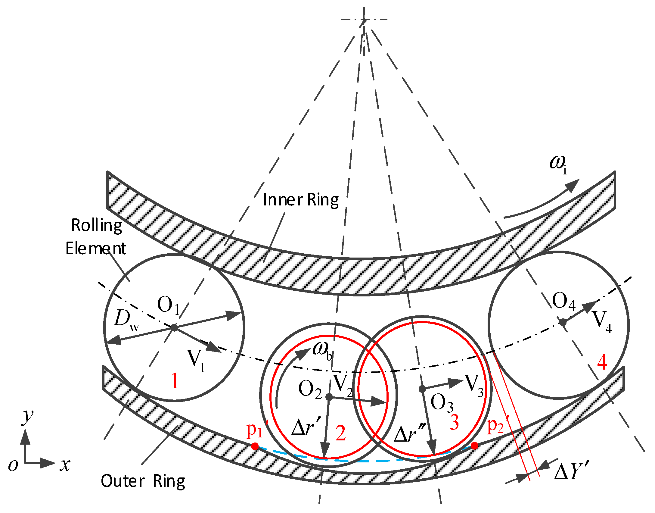
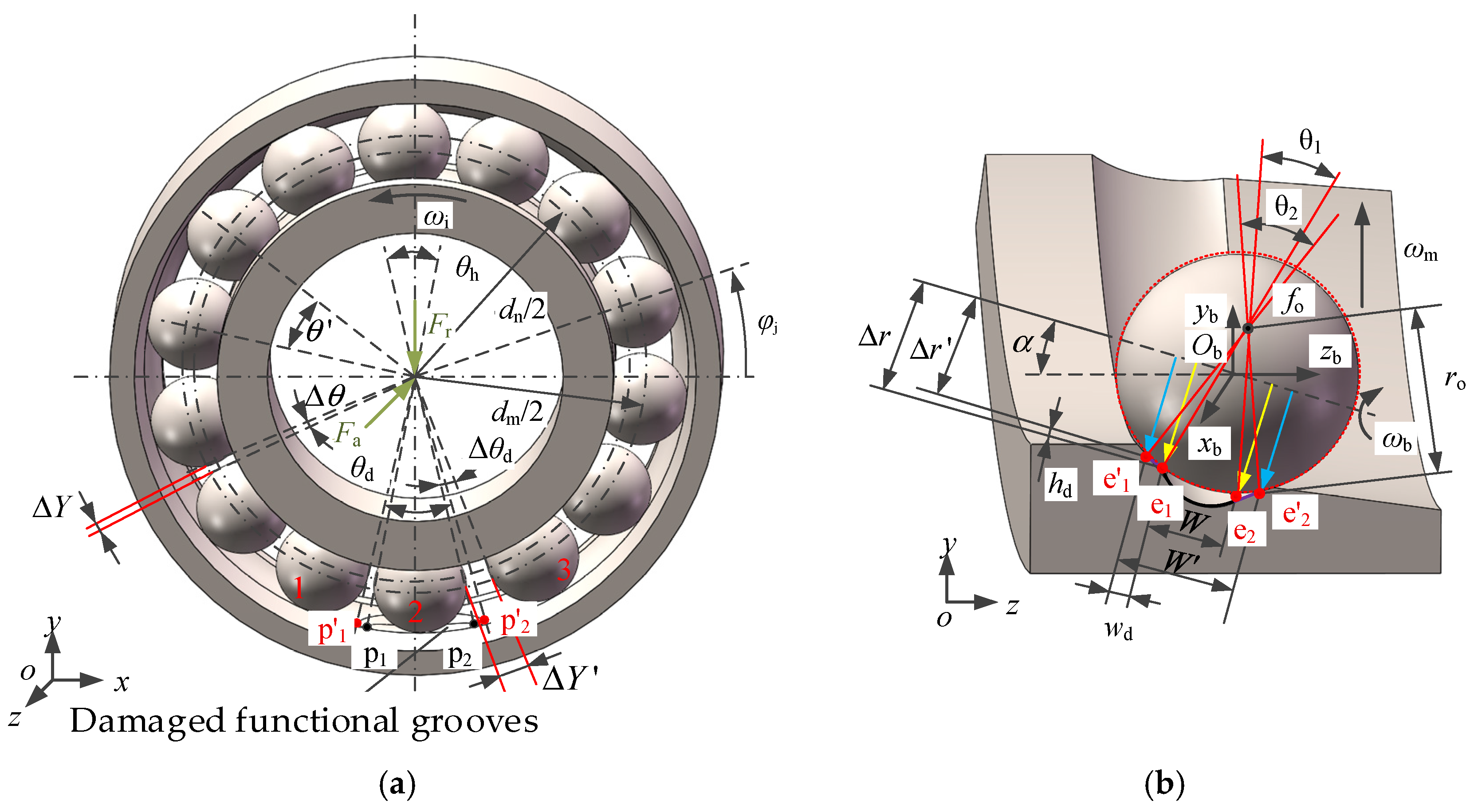
This section first analyzes the discrete states of rolling elements as they pass through locally damaged functional grooves, and presents a schematic diagram of a caged-less bearing with locally damaged functional grooves, as shown in Figure 1.
Figure 1a shows a schematic diagram of an angular contact ball bearing without a cage. A locally elliptical functional groove is designed on the outer ring raceway; this groove is located at the point of maximum radial load. The outer ring is fixed, while the inner ring rotates counterclockwise at an angular velocity. The bearing is subjected to the combined action of radial load Fr and axial load Fa. Figure 1b shows a schematic diagram of the contact between rolling element No. 2 and the local functional groove. The local functional groove is designed symmetrically along a direction perpendicular to the axis of rotation. The initial contact angle α of the rolling element on the local functional groove is defined, and the rolling element rotates driven by the inner ring of the bearing at an orbital angular velocity ωm and a rotational angular velocity ωb. Based on the cage-less ball bearing designed in Reference [26], this paper designs the system such that there is only one rolling element in each local functional groove (Figure 1a), ensuring that the number of rolling elements in the load-bearing zone remains constant to guarantee uniform load distribution.
As shown in Figure 1a, when the local functional groove is undamaged, its points of intersection with the conventional raceway along the outer ring of the bearing are p1 and p2, and the corresponding circumferential span angle of the local functional groove is θh. When the rolling element has fully entered the local functional groove from the conventional raceway, the rolling element and the local functional groove come into two-point contact. As shown in Figure 1b, when the rolling element moves to the widest part of the local functional groove, the contact points are e1 and e2. At this point, the corresponding axial span angle is θ1, and the axial distance between the two contact points is W. As the rolling element moves from the conventional raceway through the local functional groove, its radius of rotation ∆r changes with the position angle φj. This causes inconsistent movement speeds among adjacent rolling elements, resulting in a speed difference, and a discrete spacing ∆Y gradually develops between the rolling elements. Therefore, designing local functional grooves on the outer raceway can cause the rolling elements to become discrete.
As the rolling elements perform periodic motion and continuously pass through the local functional grooves, damage to these grooves causes the rolling elements to shift radially downward. At this point, the contact points between the rolling elements and the local functional grooves move to e′1 and e′2, resulting in damage width (wd) and depth (hd) of the local functional grooves. Due to the increase in the distance W’ between the rolling elements and the contact points on the damaged local functional grooves, the effective rolling radius ∆r’ decreases. According to the aforementioned rolling element separation principle, when the effective rolling radius continues to decrease with the progression of damage until it reaches a certain value, this will ultimately cause the separation distance ∆Y’ between rolling element 2 and rolling element 3 in Figure 1a to continuously increase, while rolling element 1 catches up with rolling element 2 until a collision occurs, ultimately leading to rolling element separation failure due to local functional groove damage. As the local functional groove damage progresses, it not only affects rolling element contact but also causes uneven bearing load distribution. The inner ring pushes the rolling elements outward, causing the original junction between the local functional groove and the conventional raceway to expand circumferentially to points p′1 and p′2, and the circumferential span angle of the damaged local functional groove increases to θd (Figure 1a).
Based on the above analysis of the impact of local functional groove damage on rolling element separation, it is evident that such damage directly affects the effective rolling radius of the rolling elements, which in turn affects the speed difference between adjacent rolling elements, leading to changes in the separation distance. Therefore, we first establish a relationship equation between the local functional groove damage parameters and the spacing ∆Y’ to identify the factors influencing ∆Y’, which serves as the criterion for determining rolling element spacing failure.
As shown in Figure 1a, for rolling elements with undamaged local functional grooves under uniform dispersion, the circumferential span angle θh corresponding to the local functional groove and the dispersion distance ∆Y are expressed as:
θ h = θ Δ θ = 360 Z arcsin D w d m Δ Y = Δ θ × π × D w + D m 180
where, ∆θ is the discrete angle; Z is the number of rolling elements; Dw is the diameter of the rolling elements, mm; dm is the pitch circle diameter of the bearing, mm.
Similarly, based on the geometric relationships shown in Figure 1a, expressions can be derived for the circumferential span angle θd and the discrete spacing ∆Y’ corresponding to damage in the local functional groove:
θ d = θ h + 4 arcsin w d d m + D w cos α
where, wd is the width of the localized functional groove damage, mm; α is the rolling element contact angle.
Δ Y = 2 π d n θ d 360 D w 2 Δ r 1
Based on the above analysis of the discrete spacing of rolling elements following damage to the local functional groove of a cage-less ball bearing, it can be seen that the effective radius of rotation changes as the rolling elements pass through the damaged local functional groove; therefore, it is necessary to analyze the effective radius of rotation of the bearing rolling elements.
As shown in Figure 1b, if the distance between the rolling element and the contact point of the undamaged local functional groove is W, then the axial span angle θ1 of the local functional groove can be expressed as:
θ 1 = 2 arcsin W / 2 r o
where, W is the width before local functional groove damage, mm; r0 is the radius of curvature of the outer ring groove, mm.
When the width of the contact point between the rolling element and the groove increases to W′ after local functional groove damage, and the damage width wd is introduced based on Equation (4), the axial span angle θ2 after local functional groove damage is expressed as:
θ 2 = 2 arcsin W / 2 + w d r o
Since the contact points between the rolling elements and the local functional groove shift from e1 and e2 to e′1 and e′2 along the bottom of the outer ring raceway groove, while the radius of curvature ro at the bottom of the outer ring groove remains constant, the relationship between the local functional groove damage depth hd and the axial span angles θ1 and θ2 can be derived from Equations (4) and (5) as follows:
h d = r o cos θ 1 2 r o cos θ 2 2
At this point, when the rolling element passes through the damaged area, a downward displacement occurs in the radial direction of the bearing, resulting in a damage depth. This reduces both the contact circumference and the effective radius of rotation. As shown in Figure 1b, the relationship between the effective radius of rotation ∆r′ and the damage depth hd is as follows:
Δ r = Δ r h d
Based on the previous analysis of the spacing between rolling elements passing through a locally damaged functional groove, it can be seen that the variation in the spacing between rolling elements primarily depends on the effective radius of rotation. Therefore, substituting Equations (2), (6) and (7) into Equation (3) yields the following expression for the spacing between rolling elements after damage to the local functional groove:
Δ Y = π d n 180 θ h + 4 arcsin ( w d d m + D w cos α ) D w 2 ( Δ r h d ) 1
As can be seen from Equation (8), the parameters affecting the discrete spacing of the rolling elements are primarily the radial damage depth, axial damage width, and circumferential span angle of the local functional groove, as well as the effective rolling radius. Since changes in the rolling radius directly affect the speed at which the rolling elements pass through the local functional groove, we first analyze the speed of the bearing rolling elements.

2.2. Analysis of Rolling Element Velocity in the Damaged Local Functional Groove

As shown by the discrete analysis of the damaged local functional groove described above, when the rolling element transitions from the conventional raceway into the damaged local functional groove, the contact point between the rolling element and the groove changes. A schematic diagram illustrating the motion of the rolling element within the damaged local functional groove is shown in Figure 2.
The figure shows four adjacent rolling elements successively passing through the damaged local functional groove. Rolling element 4 has already moved to the normal raceway; at this moment, as rolling element 3 is about to leave the damaged local functional groove, rolling element 2 has already entered it. The rotational radii of the four rolling elements at different positions on the damaged local functional groove have changed (Dw/2 − ∆r′ − ∆r″ − Dw/2). As noted in the previous analysis, the orbital angular velocity and linear velocity of the rolling elements have changed. According to Reference [27], the orbital angular velocity ωm and rotational angular velocity ωb of a bearing rolling element on a conventional raceway can be expressed as:
ω m = ω i 2 ( 1 D w d m cos α )
ω b = ω i d m 2 D w ( 1 D w 2 d m 2 cos 2 α )
At this point, rolling element 2 in the damaged functional groove detaches from the inner ring; the change in the radius of rotation causes the linear velocity to change. The linear velocity of rolling element 2 in the damaged functional groove is expressed as:
V 2 = ω m d m / 2 + ( D w Δ r ) cos α
Since the inner ring rotates while the outer ring remains stationary during bearing operation, when the rolling elements are located within the functional grooves of the damaged area, assuming that the rotational speed ωb of the rolling elements remains constant, the relationship between the orbital and rotational linear velocities of the rolling elements at the contact point is given by:
ω b Δ r = ω m d m / 2 + ( D w Δ r ) cos α + Δ r cos α
Substituting Equation (10) into Equation (12) yields the angular velocity of the rolling element on the local functional groove as:
ω m = ω b Δ r D w cos α + d m / 2
As shown in Figure 1a, the orbital velocity V1 of a rolling element on a conventional raceway is given by V 1 = ω m d m / 2 . Substituting Equation (13) into Equation (11) yields the velocity difference between two adjacent rolling elements on the conventional raceway and the damaged local functional groove:
Δ V = ω m d m 2 ω b Δ r ( D w Δ r ) cos α + d m / 2 D w cos α + d m / 2
Substituting Equation (9) into Equation (14) yields:
Δ V = ω i d m 4 ( 1 D w d m cos α ) ω b Δ r ( D w Δ r ) cos α + d m / 2 D w cos α + d m / 2
As can be seen from Equation (15), the velocity difference between adjacent rolling elements is related to the effective radius of rotation ∆r′ of the rolling elements in the damaged local functional groove. Based on the preceding analysis, the separation of rolling elements in a cage-less bearing depends on the velocity difference between adjacent rolling elements. The following analysis determines the variation pattern of the separation distance between rolling elements after damage to the local functional groove.
As shown in Figure 2, since the damaged local functional groove extends circumferentially to points p′1 and p′2 after damage, when rolling element 3 and rolling element 2 pass through the local functional groove, two rolling elements may simultaneously be present within the damaged local functional groove. As rolling element 3 is about to exit the damaged local functional groove, it undergoes deceleration, while rolling element 2 has already entered the damaged local functional groove. The distance between rolling elements 2 and 3 gradually decreases, potentially leading to a collision. Meanwhile, rolling element 4, which has already exited the damaged local functional groove, begins to accelerate under the drive of the outer ring, and the distance between it and rolling element 3, which is still within the damaged local functional groove, gradually increases.
From the above analysis, it can be seen that the uniform spacing between rolling elements in the undamaged functional groove is ∆Y. When two rolling elements collide within the damaged functional groove, the condition for rolling element failure is:
Δ Y 2 Δ Y
From Equation (3), the discrete spacing ∆Y between rolling elements in the undamaged local functional groove can be derived as:
Δ Y = π d n θ h 360 D w 2 Δ r 1
Using linear (16) and quadratic (17) models, the relationships between various parameters before and after damage to the local functional groove were established as follows:
Δ Y 2 π d n θ h 360 D w 2 Δ r 1
Substituting Equation (3) into Equation (18), we can determine that the range of variation in the effective rolling radius Δr’ following the discrete failure of the damaged local functional groove is:
Δ r D w Δ r θ d 2 ( D w 2 Δ r ) θ h + 2 Δ r θ d
Substituting Equations (5)–(7) into Equation (19) yields the following ranges for the changes in the depth and width of the damage in the local functional groove following the discrete failure of the rolling elements:
h d Δ r D w Δ r θ d 2 ( D w 2 Δ r ) θ h + 2 Δ r θ d w d r o sin arccos ( r o cos ( θ 1 / 2 ) A ) r o W 2
where, A = Δ r D w Δ r θ d 2 ( D w 2 Δ r ) θ h + 2 Δ r θ d .
Substituting Equation (19) into Equation (15), the velocity difference between adjacent rolling elements when they collide following damage to a local functional groove is expressed as:
Δ V ω m d m ω b d m + ( D w Δ r ) cos α D w Δ r θ d d m + D w cos α ( 2 ( D w 2 Δ r ) θ h + 2 Δ r θ d )
Based on Equations (19) and (21), it can be seen that damage to the local functional groove alters the rolling element’s radius of rotation, which in turn changes the time-varying displacement characteristics of the rolling element over the damaged local functional groove. This, in turn, leads to changes in the velocity difference between adjacent rolling elements, causing collisions. Therefore, based on an analysis of the dynamic characteristics of rolling elements over the damaged local functional groove, this study investigates the time-varying displacement characteristics and collisions of the rolling elements.

3. Analysis of the Dynamic Characteristics of Rolling Elements in Caged-Less Ball Bearings with Locally Damaged Grooves

3.1. Analysis of the Time-Varying Characteristics of Rolling Element Displacement in Locally Damaged Grooves

  • Time-dependent displacement of rolling elements in undamaged local functional grooves
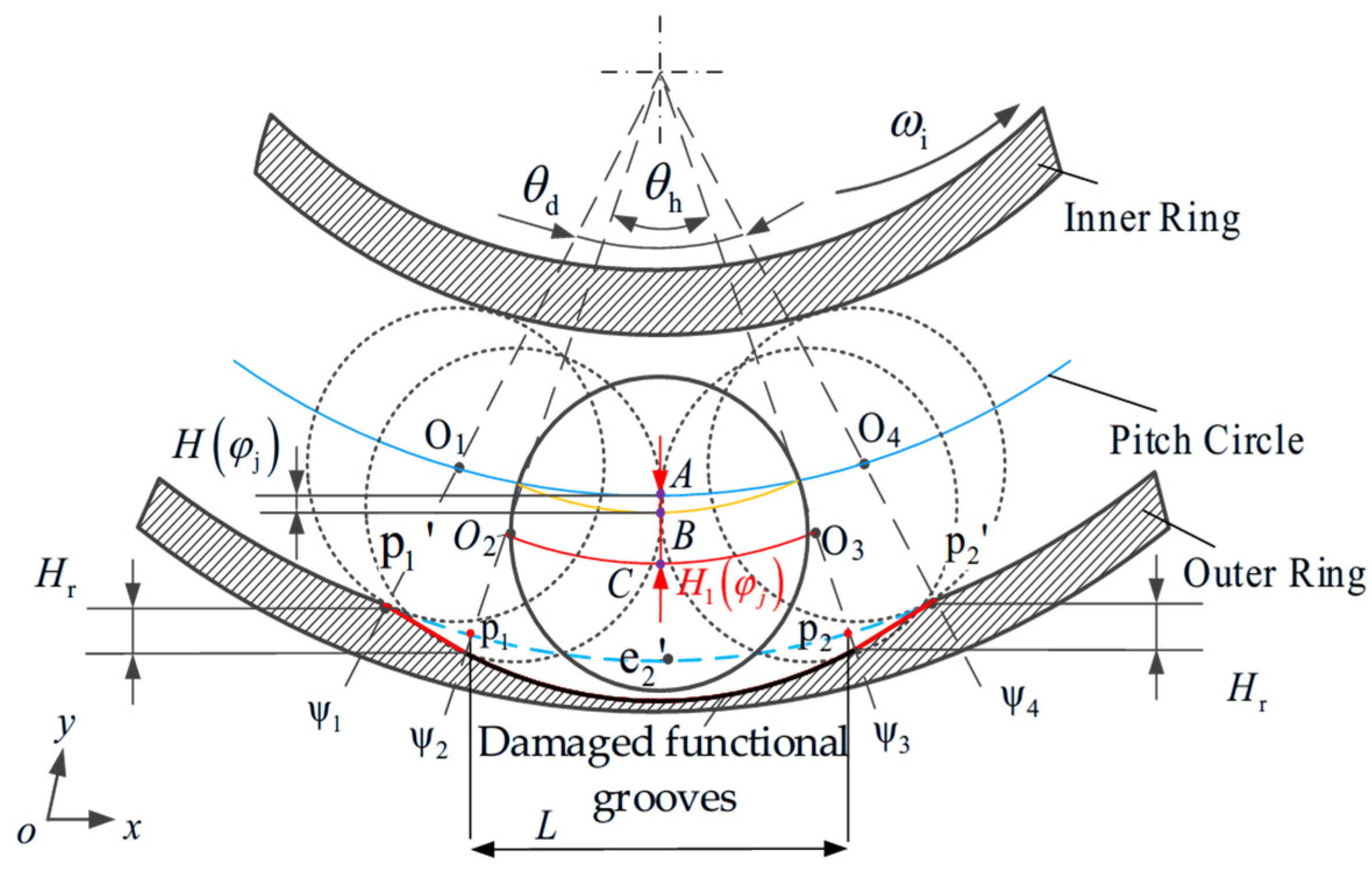
The local functional groove designed in this paper is an elliptical structure. When the rolling element passes through the local functional groove, it maintains two-point contact while disengaging from the inner ring (Figure 1b). As the rolling element moves across the local functional groove, time-varying displacement occurs. Figure 3 illustrates the time-varying displacement of the rolling element before and after passing through the local functional groove. To more clearly illustrate the contact between the rolling element and the local functional groove, the figure has been magnified. In the figure, the undamaged local functional groove corresponds to a circumferential span angle of θh. As the rolling element passes through the local functional groove, the center of the ball moves radially. In the figure, H(φj) represents the time-varying displacement of the rolling element as a function of position. Based on the geometric relationships shown in the figure, the expression for the position L(φj) of the contact point of the rolling element relative to the starting end of the local functional groove is:
L φ j = L 2 cos α D w / 2 + d m / 2 tan 3 π 2 mod φ j
where, φj is the angular position of the rolling element; L is the length of the undamaged local functional groove, mm; Dw is the diameter of the rolling element, mm; dm is the pitch circle diameter of the bearing, mm.
The distance W(φj) between the two contact points of the rolling element and the undamaged elliptical local functional groove also varies with L(φj), and its expression is given by:
W φ j = W 1 L φ j L / 2 2 L 2 / 4
where, W is the maximum width of the rolling element and the local functional groove, mm.
After determining the distance W(φj) between the two contact points of the rolling element in the local functional grooves e1 and e2, it follows from the contact geometry of the rolling element in the local functional grooves that the equation for the time-varying displacement of the rolling element in an undamaged elliptical local functional groove can be expressed as:
H φ j = r 0 2 W φ j 2 1 2 D w 2 2 W φ j 2 1 2 + D w 2 r 0
where, r0 is the radius of curvature at the bottom of the bearing raceway, mm.
2.
Time-dependent displacement of rolling elements in a damaged local functional groove
Based on the aforementioned analysis of local functional groove damage, the damaged local functional groove is divided into three regions, as shown in Figure 3. In the region from ψ2 to ψ3: In this region, the time-varying displacement of the rolling element is primarily attributed to the combined effects of the local functional groove damage width wd and damage depth hd. The time-varying displacement H1(φj) of the rolling element on the damaged elliptical local functional groove is considered; In the two regions (ψ1–ψ2) and (ψ3–ψ4): In these two regions, the time-varying displacement of the rolling elements is primarily due to radial squeezing. The figure shows that the maximum time-varying displacement of the rolling elements within these two regions is Hr.
In the region (ψ2–ψ3), the time-varying displacement of the rolling elements is caused by the local functional groove damage parameters. Therefore, according to Equation (24), the time-varying displacement H1(φj) of the rolling elements on the damaged local functional groove is given by:
H 1 φ j = r 0 2 W φ j + w d 2 1 2 D w 2 2 W φ j + w d 2 1 2 + D w 2 r 0
As can be seen from Equations (5) and (6), the damage depth hd is related to the damage width wd; therefore, in Equation (25), the severity of local functional groove damage is characterized by the parameter wd.
As shown in Figure 3, in the regions (ψ1–ψ2) and (ψ3–ψ4), the original contact points p1 and p2 with the conventional raceway extend outward to p′1 and p′2, respectively, due to damage to the local functional groove. Therefore, when the rolling element moves from p’1 to p1, the time-varying displacement of the rolling element as a function of position is expressed as:
H r 1 φ j = H r mod ( ( φ j 3 π / 2 + θ d / 2 ) , 2 π ) ψ 2 ψ 1
Similarly, when the rolling body moves from p2 to p′2, the expression for its time-dependent displacement as a function of position is:
H r 2 φ j = H r mod ( ( 3 π / 2 + θ d / 2 φ j ) , 2 π ) ψ 4 ψ 3
In summary, when a rolling element passes through the locally damaged groove (i.e., from p′1 to p′2), the equation describing the time-varying displacement of the rolling element as a function of position can be expressed as:
H = H r 1 φ j ψ 1 mod ( φ j , 2 π ) ψ 2 H 1 φ j   ψ 2 < mod ( φ j , 2 π ) < ψ 3 H r 2 φ j ψ 3 mod ( φ j , 2 π ) ψ 4
The positions of the contact points p′1 and p′2 between the damaged local functional groove and the conventional raceway depend on the circumferential span angle; therefore, the positions of the two ends of the damage can be expressed as:
ψ 1 = 3 π 2 θ d 2 ψ 4 = 3 π 2 + θ d 2
Substituting Equation (2) into Equation (29) yields the circumferential position of the local damage function slot as:
ψ 1 = 3 π 2 θ h + 4 arcsin w d d m + D w cos α 2 ψ 4 = 3 π 2 + θ h + 4 arcsin w d d m + D w cos α 2
Based on the above analysis of the rolling elements’ motion through the damaged functional groove, a time-varying displacement model was established for the rolling elements as they pass through the damaged functional groove, laying the groundwork for subsequent analysis of rolling element collisions and bearing vibrations caused by damage to the functional groove.

3.2. Analysis of the Time-Varying Characteristics of Rolling Element Contact Stiffness in a Locally Damaged Groove

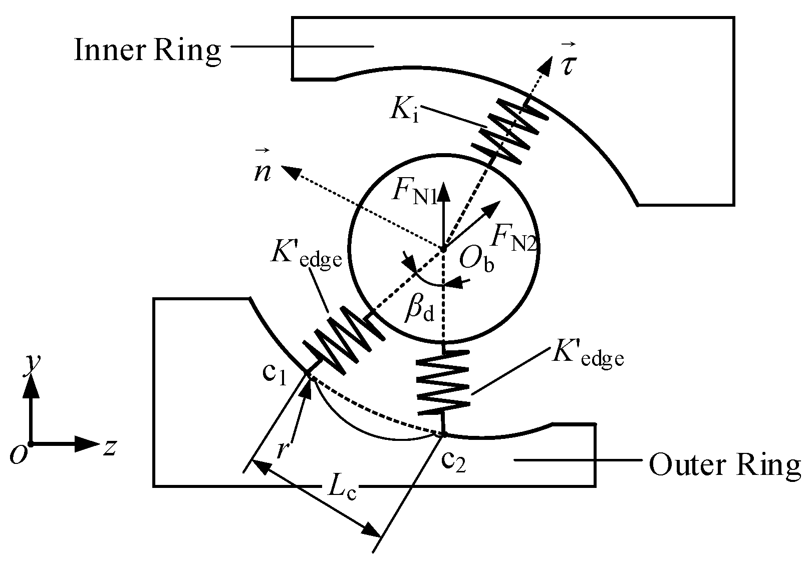
Based on the preceding analysis, the rolling element undergoes time-varying displacement as it passes through the damaged functional groove. Since the damaged functional groove extends circumferentially, the time-varying displacement of the rolling element upon entry and before exit is insufficient to offset the contact deformation of the ring. At this point, although the rolling element and the damaged functional groove are in two-point contact—as shown by contact points c1 and c2 in Figure 4—the rolling element remains in contact with the bearing inner ring because the deformation has not yet recovered. To analyze the time-varying stiffness of the rolling element, the contact stiffness model shown in Figure 4 is presented for the rolling element as it enters the damaged functional groove.
As shown in Reference [28], the contact stiffness Kedge between the rolling element and the edge of the local functional groove at the damaged site is given by:
K edge = 4 3 E * R * 1 / 2
where, R* is the equivalent radius of curvature at the point of contact between the rolling element and the local functional groove; E* represents the equivalent elastic modulus at the contact point between the rolling element and the local functional groove.
After converting the equivalent radius of curvature [28], Equation (31) can be expressed as:
K edge = 4 3 E 2 1 v 1 2 + E 1 1 v 2 2 E 1 E 2 D w 2 r o r D w + 2 r ( 2 f o D w ) 0.25
where, ro is the curvature radius of the outer raceway groove, in mm; r is the curvature radius at the edge of the local functional groove damage, in mm; E is the elastic modulus of the material, in GPa; v is the Poisson’s ratio of the material.
As shown in Figure 4, the rolling element is supported at the damaged local functional groove by contact points c1 and c2, and is subjected to support forces FN1 and FN2. The time-varying displacement of the rolling element’s center of mass Ob is along the direction of the vector τ , and the normal vector of the trajectory of the center of mass’s time-varying displacement is n . According to References [29,30], the equivalent contact stiffness between the rolling element and the functional groove at the damage site can be expressed as:
K edge = 2 K edge cos 2 β d / 2 + 2 T sin ρ sin β d / 2 D w / 2 ρ D w
where, ρ is the radius of curvature of the rolling element’s center-of-mass trajectory, in mm. T is the spring force, which is numerically equal to the supporting force on the rolling element. βd is the angle between the supporting forces acting on the rolling element, expressed as β d = 2 arcsin ( L c / D w ) .
When the trajectory of the rolling body’s center of mass is a straight line, the radius of curvature ρ tends to infinity, and the equivalent contact stiffness Kedge can be simplified to:
K edge = 2 K edge cos 2 β d / 2
After determining the equivalent contact stiffness between the rolling elements and the damaged local functional groove, the contact stiffness between the rolling elements and the inner and outer rings of the bearing at the conventional raceway is:
K b = 1 K i 2 / 3 + K o 2 / 3 3 / 2
Similarly, by substituting the contact stiffness between the rolling element Kedge and the damaged functional groove in the outer ring into Equation (35), we obtain the contact stiffness of the rolling element as it passes through the damaged functional groove:
K b = 1 K i 2 / 3 + K edge 2 / 3 3 / 2
Therefore, the time-varying contact stiffness of the rolling elements as they complete one revolution within the bearing can be expressed as a function of position:
K = K b ψ 1 < mod ( φ j , 2 π ) < ψ 4 K b       other
As can be seen from Equation (37), the time-varying contact stiffness of the rolling elements in cage-less ball bearings is related to damage in the local functional grooves; the derivation of this equation provides a theoretical basis for subsequent vibration equations for bearing rolling elements.

3.3. Analysis of the Instantaneous Forces Resulting from Collisions Between Rolling Elements in a Locally Damaged Groove

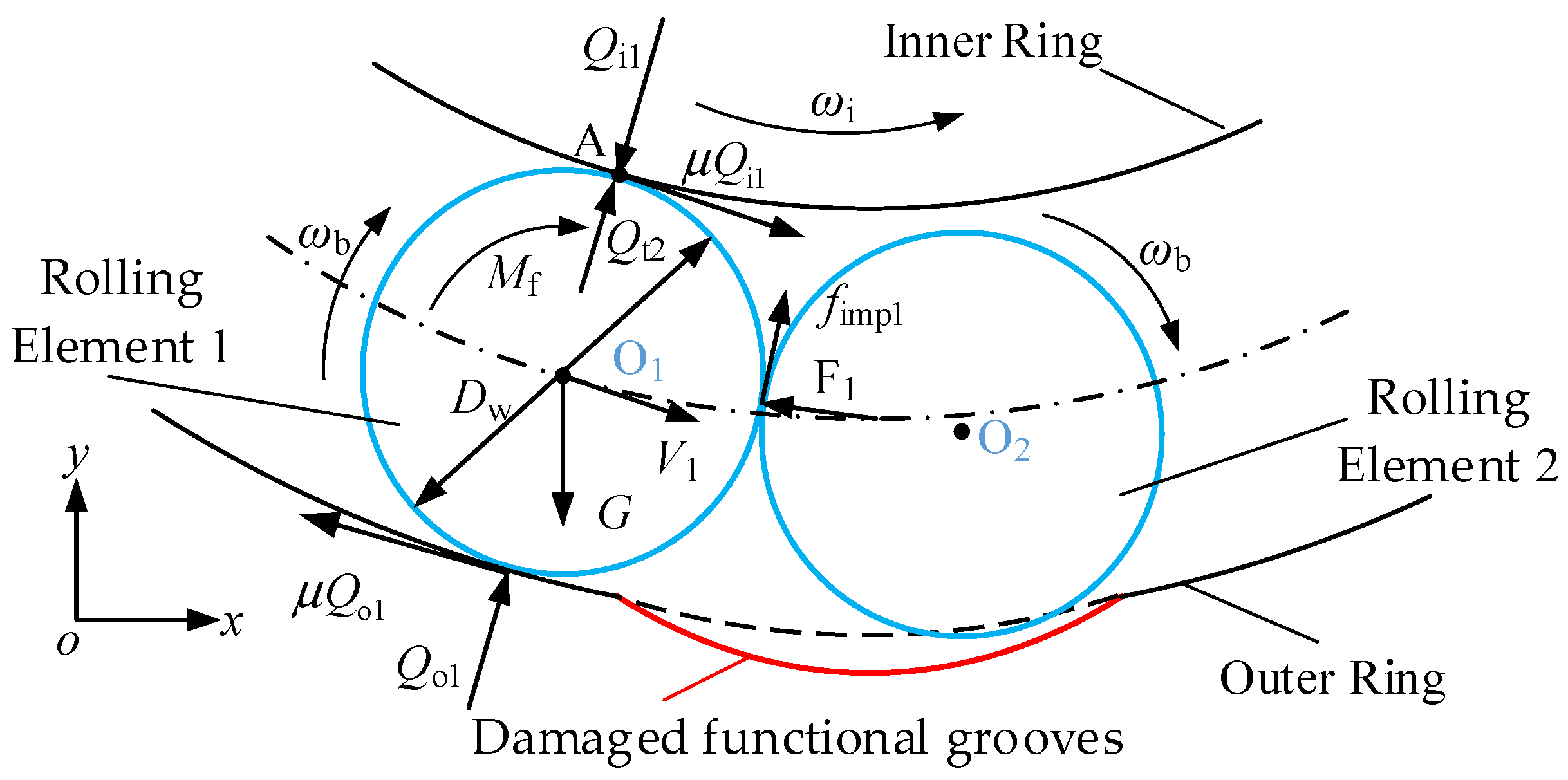
As the damage to the local functional groove worsens, rolling element 2 enters the damaged local functional groove first and separates from the inner ring, followed closely by rolling element 1, which has not yet entered the damaged local functional groove. Based on the preceding analysis, when the relative velocity between rolling element 1 and rolling element 2 satisfies Equation (27), the discrete failure of adjacent rolling elements will result in a collision. Under the force of the collision, the rolling elements will squeeze the inner ring, Figure 5 illustrates the force distribution during the collision between adjacent rolling elements 1 and 2.
In Figure 5, rolling element 1 is analyzed as the force-receiving body. When rolling element 1 moves along the conventional raceway, under the action of the inner and outer ring contact forces Qi1 and Qo1, rolling element 1 generates friction forces with the rings. As shown in the figure, these two friction forces create a resistive torque Mf that affects the velocity of rolling element 1. Under the action of the collision force F1, the collision between adjacent rolling elements generates a friction force fimp1. Correspondingly, a friction torque is also generated at the point of contact. Therefore, under the combined action of these forces, rolling element 1 will exert an instantaneous force Qt2 on the inner ring at contact point A, while simultaneously generating a torque to balance the aforementioned friction torque at the point of contact. Since the instantaneous force will cause vibration in the bearing inner ring, it is necessary to establish an equation for the instantaneous force to provide the basis for the input conditions required to solve the subsequent bearing vibration equation.
Since the duration of the collision between rolling elements is extremely brief, the deformation caused by the collision is considered elastic [30]. When two rolling elements collide while rolling at velocities V1 and V2, respectively, and taking into account the change in velocity resulting from the deformation caused by the collision, the relationship between deformation and velocity can be expressed as:
Δ V = d δ imp d t = V 1 - V 2
where, ∆V is the relative velocity between the two rolling bodies, in m∙s−1; δimp is the deformation caused by the collision between the two rolling bodies, in mm.
At any given instant, the normal force resulting from the collision between the rolling bodies is:
F 1 = m d V 1 d t = m d V 2 d t = K bb δ imp 3 / 2
where, m is the mass of the rolling element, in kg; Kbb is the contact stiffness between the rolling elements, in N∙m−1.
According to Reference [31], integrating Equation (39) yields the following expression:
m 1 + m 2 m 1 m 2 F 1 = d ( V 1 - V 2 ) d t = d 2 δ imp d t 2
Integrating Equation (20) yields:
1 2 Δ V 2 d δ imp d t 2 = 2 5 K bb m δ imp 5 / 2
At the point of maximum deformation due to the impact, the radius imp/dt = 0 of the rolling element is given by combining Equations (40) and (41) to obtain the maximum compressive deformation as:
δ imp * = 5 m Δ V 2 4 K bb 2 / 5
By integrating Equation (40) twice, we can derive the dynamic expressions for deformation and time as follows:
t * = δ imp * Δ V d ( δ imp / δ imp * ) 1 ( δ imp / δ imp * ) 5 / 2 1 / 2
After reaching the moment of maximum compression t*, the deformation caused by the rolling elements colliding is fully restored, allowing us to calculate the total collision time as:
T c = 2 t * = 2 δ imp * Δ V 0 1 d ( δ imp / δ imp * ) 1 ( δ imp / δ imp * ) 5 / 2 1 / 2 = 2.94 δ imp * Δ V
After calculating the contact deformation δ*imp of the rolling element, the friction force during the collision of the rolling elements can be determined as follows:
f imp 1 = μ K bb δ imp 1.5
After calculating the friction force acting on the rolling element at the point of contact, it can be determined that the friction torque is fimp1Dw/2. According to Reference [32], the instantaneous force exerted by rolling element 1 on the inner ring of the bearing is calculated using the law of conservation of angular momentum:
( f imp D w / 2 μ Q t 2 D w / 2 ) ω b ω b T c = 1 2 I ω b 2 1 2 I ω b 2
where, I is the moment of inertia of the rolling element, kg m 2 ; Dw is the diameter of the rolling element, mm; Qti is the instantaneous force acting on the inner ring during the collision, N.
Since rolling element 2 disengages from the inner ring at the damaged local groove when rolling elements 1 and 2 collide, it can be assumed that the rotational speed of rolling element 1 remains unchanged after the collision, i.e., ω b = ω b . Simplifying Equation (46) yields the load Qti imposed on the inner ring during the collision:
Q t 2 = f imp μ 2 I ω b Δ V 2.94 δ imp * μ D w
Based on the analysis of the dynamic characteristics of rolling elements in the functional grooves at the damaged site, this study established models for the time-varying displacement and time-varying stiffness of the rolling elements, as well as the instantaneous forces exerted on the inner ring due to collisions caused by discrete failures of adjacent rolling elements. This provides the theoretical basis and computational conditions for deriving the vibration equations in Chapter 3.

4. Derivation of the Vibration Equation for Locally Damaged Grooved Bearings

4.1. Contact Model of a Grooved Bearing with Localized Damage

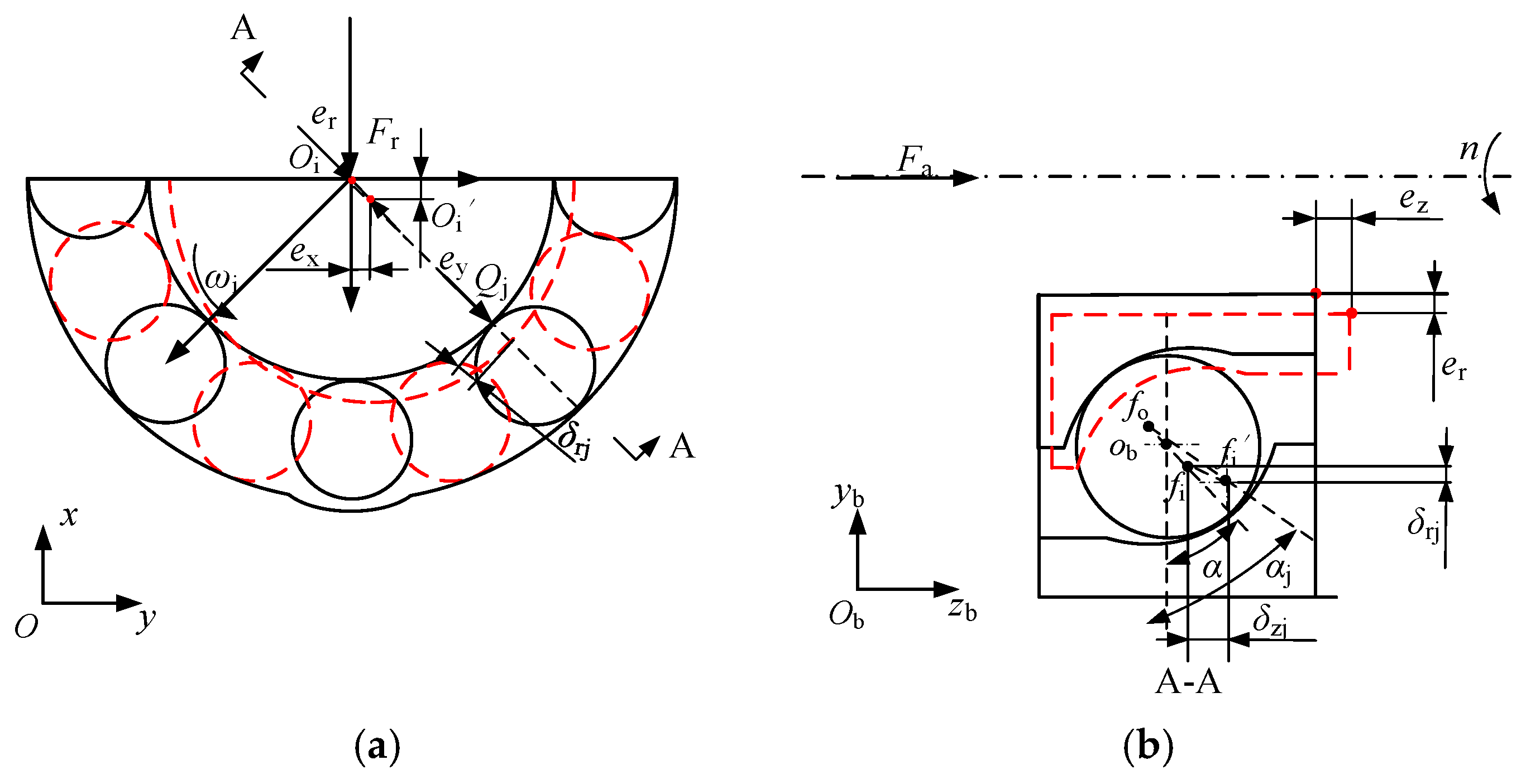
During bearing operation, the elastic deformation between the rolling elements and the rings is directly related to the angular position of the rolling elements, their radial displacement, and the displacement of the inner ring’s center of mass. Figure 6 illustrates a contact model showing the displacement changes of the inner ring of a functionally grooved bearing under load.
When the bearing is at rest, the effect of clearance is neglected. In a cage-less angular contact bearing, there is an initial contact angle α between the rolling elements and the inner ring raceway. When the bearing is subjected to an axial load Fa and a radial load Fr, the center of the inner ring, Oi, moves to point Oi′. At this point, the inner ring generates displacements ex and and ey in the radial plane, and a distance ez along the axial direction (negative z-axis). The center of curvature of the inner ring raceway moves from fi to fi′, as shown in Figure 6. Under the combined load, the jth rolling element located in the load-bearing zone comes into contact with the inner and outer rings of the bearing, resulting in a total contact deformation δj. To facilitate the analysis of the contact deformation between the rolling element and the inner and outer rings, a cross-section is taken along the ybobzb plane of the jth rolling element’s coordinate system (section A-A), yielding the contact deformation shown in Figure 6b). Based on trigonometric relationships, the radial contact deformation of the rolling element δrj can be obtained as:
δ rj = e x cos φ j + e y cos φ j
The axial contact deformation δzj is numerically equal to the inner ring’s axial displacement ez; therefore, the total contact deformation δj of the rolling elements and raceways in a conventional rolling element bearing is:
δ j = δ rj 2 + δ zj 2
where, φj is the angular position of the jth rolling element, which is expressed as:
φ j = φ 1 + 2 π j 1 Z + ω m t
where, φ1 is the initial angular position of the rolling element when j = 1; Z is the number of rolling elements; ωm is the angular velocity of the rolling elements.
As discussed regarding the analysis of rolling element motion, when a rolling element first enters the region between ψ1–ψ4 and contacts the local functional groove, it moves radially along the outer ring of the bearing. At this point, the deformation of the contact between the rolling element and the ring is reduced due to the time-varying displacement H. Therefore, the total deformation δj, taking into account the time-varying displacement H, is given by:
δ j = e x cos φ j + e y cos φ j H cos α 2 + e z H sin α 2
Based on the above analysis, when the jth rolling element moves, the total deformation of the rolling element and the raceway is divided into two parts: one corresponding to the conventional raceway and the other to the local functional groove. Therefore, δj is a piecewise function of the time-varying displacement H:
δ j = e x cos φ j + e y cos φ j H cos α 2 + e z H sin α 2   ψ 1 φ j ψ 4 e x cos φ j + e y cos φ j 2 + e z 2     otherwise
Since the bearing is in a stationary state under axial and radial preload, based on bearing statics theory, the effect of the rolling element’s center of mass displacement on the bearing contact angle is neglected. The bearing contact angle under preload is simplified as the change in the curvature center of the inner and outer raceways. Considering the time-dependent displacement of the rolling element due to damage in the functional groove, the contact angle αj between the rolling element and the raceway is given by:
α j = arctan A 0 cos α 0 + δ rj A 0 sin α 0 + δ zj
where, A0 is the distance between the centers of curvature of the bearing inner ring, A 0 = r i + r o D w ; ri is the radius of curvature of the inner ring raceway, mm; ro is the radius of curvature of the outer ring raceway, mm.
The contact force Qj between the rolling elements and the raceways is related to the elastic contact displacement δj between the rolling elements and the raceways. This is analyzed and calculated using Hertz contact theory:
Q j = K δ j 1.5
where, K represents the time-varying contact stiffness of the rolling elements in the bearing.
When the rolling elements come into contact with the inner and outer rings of the bearing in the load-bearing zone, the contact force acting on the inner ring is the resultant force of the contact forces exerted by each rolling element on the inner ring. By decomposing the contact force resulting from the deformation of the inner ring into its components along the x, y, and z axes, we obtain the components F = [Fix, Fiy, Fiz], which are:
F ix = j = 1 N Q j cos φ j cos α j F iy = j = 1 N Q j sin φ j cos α j F iz = j = 1 N Q j sin α j

4.2. Establishment of Vibration Equation

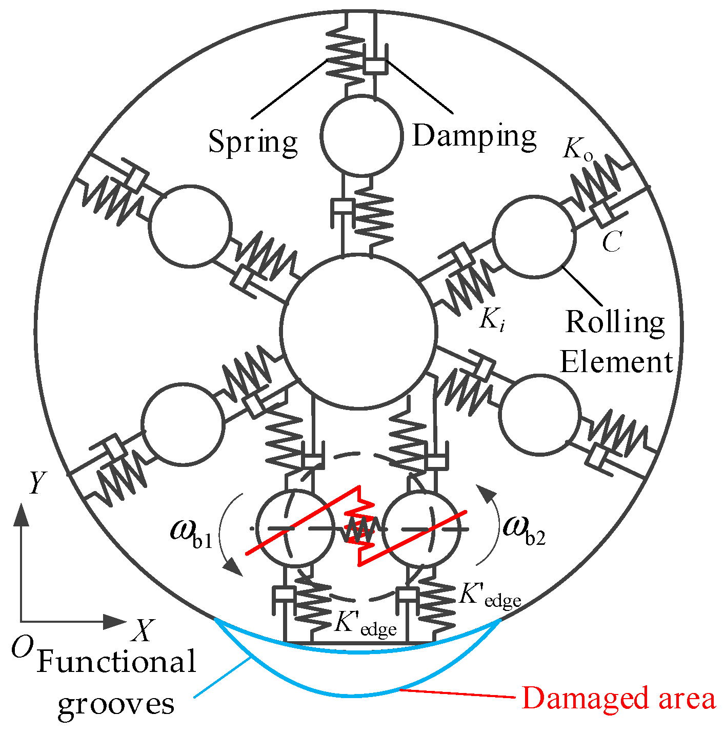
As can be seen from the above analysis, as the rolling elements move and their positions change, both the contact deformation and contact forces between the rolling elements and the rings vary. Furthermore, the instantaneous forces caused by collisions between rolling elements will affect the contact characteristics of the bearing inner ring. To analyze the vibration characteristics of the bearing when the local functional groove is damaged, the model of a cage-less bearing with a damaged local functional groove is simplified into a spring-damper system based on the contact model of the damaged local functional groove, and a vibration model for the damaged local functional groove is constructed, as shown in Figure 7. Based on the analysis in Chapter 2, the contact stiffness between the rolling elements and the inner ring is denoted as Ki. When the rolling elements pass through the damaged functional groove, the contact stiffness at the edge of the damaged groove is Kedge; when located on the conventional raceway, the contact stiffness between the rolling elements and the outer ring is Ko. C represents the damping coefficient between the rolling elements and the raceway.
This chapter primarily investigates the vibration characteristics of the bearing inner ring under the condition of localized functional groove damage, caused by contact collisions between failed rolling elements and uneven load distribution. These collisions occur only within the radial plane of the bearing; vibrations caused by compression of the bearing inner ring are not considered. Therefore, a vibration equation for the bearing inner ring is established. To analyze the model’s accuracy by focusing on primary factors while simplifying calculations by neglecting secondary factors, the following assumptions are made:
  • Only Hertzian contact deformation occurs between the rolling elements and the raceway; plastic deformation caused by the contact materials is neglected, and microscopic sliding friction within the contact area is disregarded;
  • The rolling elements undergo pure rolling motion on the raceways; the gyroscopic motion and sliding effects of the rolling elements are neglected;
  • The influence of the lubricating oil film between the rolling elements and raceways on motion and contact characteristics is neglected;
  • During bearing operation, the load and inner ring rotational speed are stable with no fluctuations.
Based on Newton’s second law and considering the time-varying displacement and stiffness caused by damage to the local functional groove, the vibrational differential equation for the inner ring of a cage-less ball bearing with a damaged local functional groove is established as follows:
m i x ¨ i + c x ˙ i = λ j F i x + Q t 2 cos α sin ψ 1 m i y ¨ i + c y ˙ i = λ j F i y + Q t 2 cos α sin ψ 1 F r m i z ¨ i + c z ˙ i = λ j F i z + Q t 2 sin α F a
where: mi is the mass of the bearing inner ring and the main shaft, kg; x ˙ i , y ˙ i , and z ˙ i are the velocities of the inner ring in the x, y, and z directions, respectively, in m/s; x ¨ i , y ¨ i , and z ¨ i are the vibration accelerations of the inner ring in the x, y, and z directions, respectively, in m∙s−2; Fa is the axial load borne by the bearing, in N; Fr is the radial force, in N; λj is the contact deformation control coefficient used to ensure that the rolling elements remain within the load-bearing zone [33].
When the rolling elements deform upon contact with the raceway under the action of an external load, the coefficient λj is set to 1; otherwise, it is set to 0. The control coefficient is:
λ j = 1 δ j 0 0 δ j < 0

5. Numerical Analysis of Local Functional Slot Vibrations Due to Damage

5.1. Numerical Solution of the Vibration Equation for a Functionally Damaged Groove

Taking a cage-less angular contact bearing with an inner diameter of 30 mm and an outer diameter of 62 mm as an example, this study analyzes the vibration characteristics of a cage-less bearing with localized damage to the functional grooves. The basic parameters of the bearing, determined based on its operating conditions, are shown in Table 1; the basic parameters of the bearing material are shown in Table 2; and the initial solution parameters and the load on the inner ring are shown in Table 3.
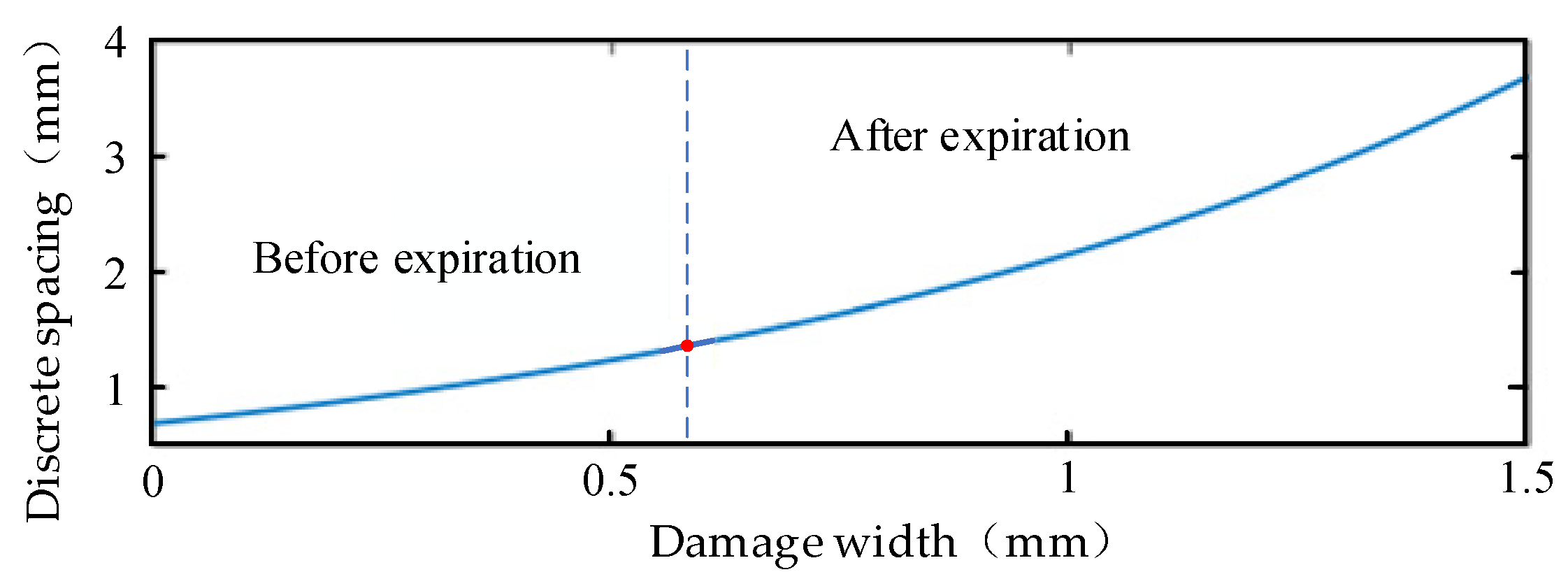
To determine the effect of different damage levels on bearing vibration, it is necessary to calculate the critical value of the local functional groove damage width wd. Combining this with the discrete failure condition Equation (8) presented earlier, the relationship between the discrete spacing of the rolling elements and the local functional groove damage width is analyzed, as shown in Figure 8.
As shown in Figure 8, when the local functional groove is undamaged, the discrete spacing between rolling elements is 0.68 mm (wd = 0). According to Equation (21), the discrete spacing when rolling elements fail is 1.361 mm; at this point, the critical damage width wd is determined to be 0.5868 mm. Therefore, this paper selects two damage widths: wd = 0.1 mm (below the critical value) and wd = 0.59 mm (with severe damage), to determine the effects of time-varying displacement H and time-varying stiffness K on the bearing vibration characteristics under these two conditions.
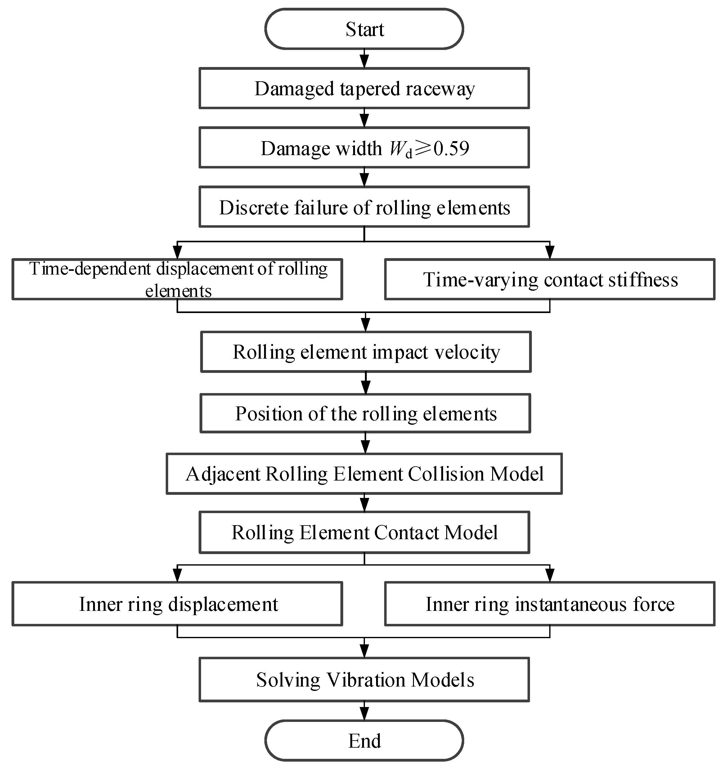
In this paper, MATLAB (R2026a) was used for programming, and the fixed-step fourth-order Runge-Kutta algorithm was employed to numerically solve the vibration equations. Initial integration values were obtained using a static method. Based on the damage width critical value, the time-varying displacement of the rolling elements, time-varying stiffness, and collision forces between rolling elements were calculated, ultimately yielding the vibration responses of the bearing inner ring, the rolling elements’ displacement, velocity, and acceleration vibration responses. Through numerical analysis of the vibration acceleration response, the vibration spectrum information of the local functional groove damage in the cage-less bearing is calculated, allowing for an in-depth analysis of the impact of local functional groove damage on the bearing’s vibration characteristics and the discrete effects of rolling element motion. By solving the phase diagram of the bearing’s vibration response, the motion state of the bearing inner ring is determined.
To improve the convergence speed of the solution, the solution step size is set to adaptively change with the bearing rotational speed, with the calculation step size set to:
d t = ( 2 π / ω i ) / N P
where, ωi is the inner ring rotational speed, in min−1; NP is the accuracy coefficient, NP = 30,000.
In this paper, the rotational speeds of the bearing inner ring were set to 1800 min−1, 3000 min−1, and 8000 min−1, respectively. The solution accuracies of the vibration differential equation were found to be 1.11 × 10⁻⁶ s, 6.67 × 10⁻⁷ s, and 2.51 × 10⁻⁷ s, respectively. Based on these results, the time step was input into MATLAB for programming, and the solution process for the vibration differential equation is shown in Figure 9.

5.2. Time-Domain Analysis of Vibration Acceleration in Function Slot Bearings with Local Damage

The purpose of analyzing the inner ring acceleration is to determine the extent of bearing vibration. In this section, we calculate the acceleration curves for two cases where the inner ring rotational speed is 1800 min−1, and the width of the local functional groove damage is 0.1 mm and 0.59 mm, respectively. To ensure greater accuracy, the vibration signals were collected during the bearing’s steady-state operation. Figure 10 shows the time-domain signal results for the inner ring acceleration when the width of the local functional groove damage (wd) is 0.1 mm.
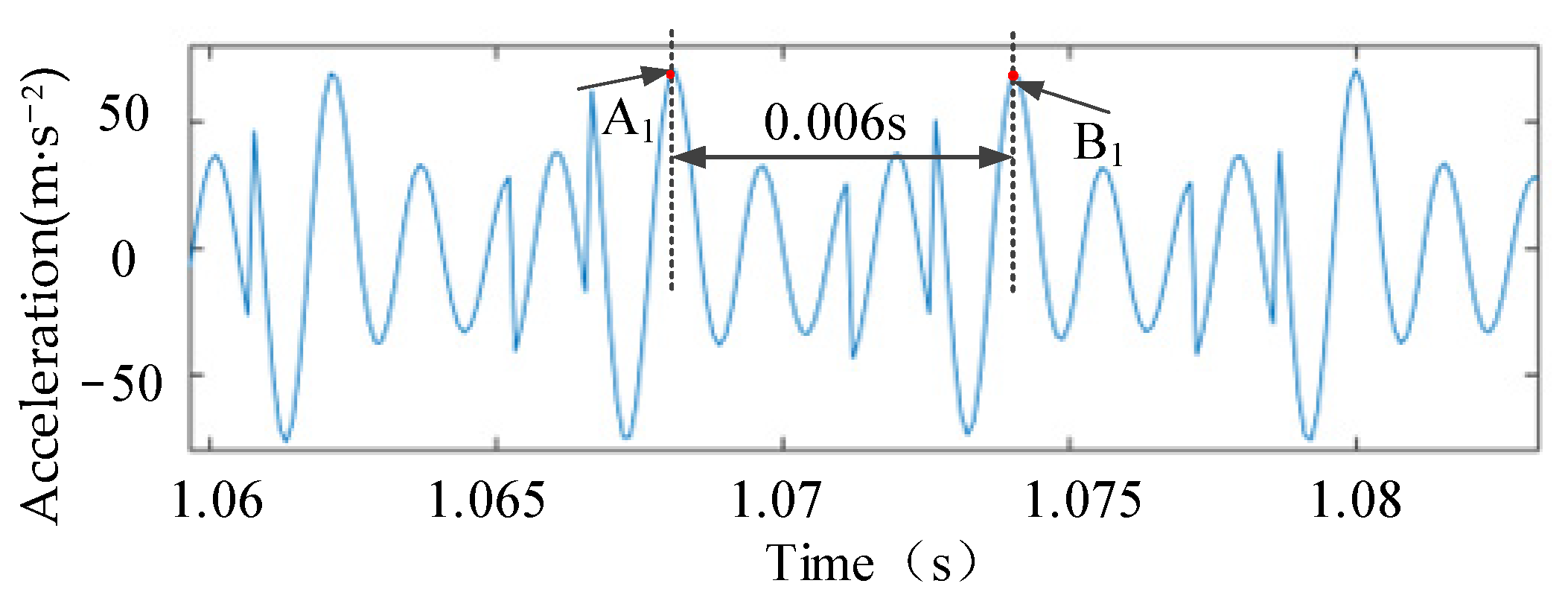
As shown in Figure 10, the acceleration amplitude exhibits distinct periodic characteristics with a stable amplitude, indicating that the bearing rolling elements are evenly loaded. This suggests that even when the width of the local functional groove damage is wd = 0.1 mm, the rolling elements can still separate, causing the inner ring vibration to vary periodically. To determine the time interval between adjacent acceleration peaks in the inner ring of the cage-less bearing with a damaged functional groove, the time range from 1.06 to 1.085 s in Figure 10 was selected for magnification, as shown in Figure 11.
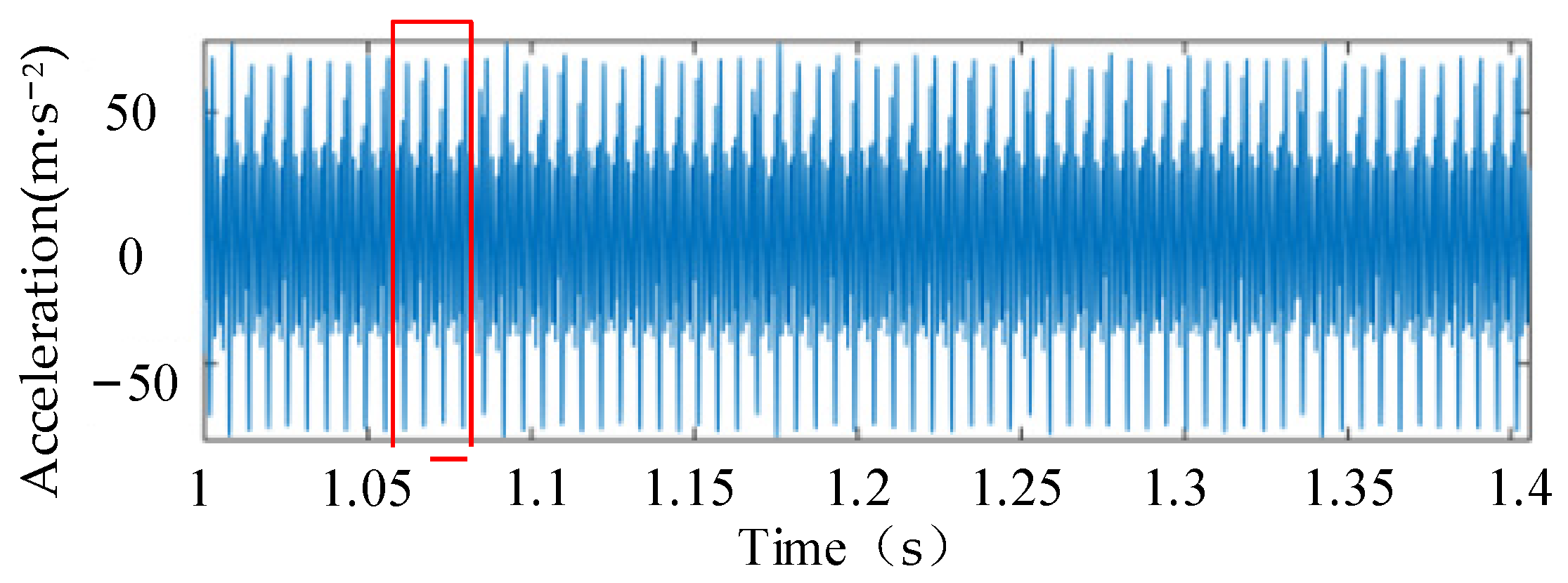
As shown in Figure 11, the maximum amplitude of the acceleration curve caused by the functional groove in the damaged area is approximately 70 m/s2. The peaks A1 and B1 exhibit periodic variations, with an interval of approximately 0.006 s between them. This indicates that the vibration frequency of the inner ring at the damaged functional groove is 166.67 Hz. Combining the bearing parameters provided in Table 1, the theoretically calculated vibration frequency at an inner ring rotational speed of 1800 min−1 is 167.998 Hz. At this point, the rolling elements are exactly at the uniform discrete state with a ball spacing of 0.68 mm. Therefore, since the frequencies from the numerical solution and the theoretical calculation are essentially consistent, it can be concluded that the rolling elements remain discrete during motion. This is primarily because, although the local functional groove is damaged, the damage width is only 0.1 mm, so it does not affect the discrete state of the rolling elements. The numerical solution results are consistent with the theoretical analysis.
Similarly, the acceleration curve was calculated for a case where the inner ring rotational speed is 1800 min−1 and the local functional groove damage width is 0.59 mm. The vibration signal was analyzed during the bearing’s stable operating phase. Figure 12 shows the time-domain acceleration signal of the inner ring for a local functional groove damage width of wd = 0.59 mm.
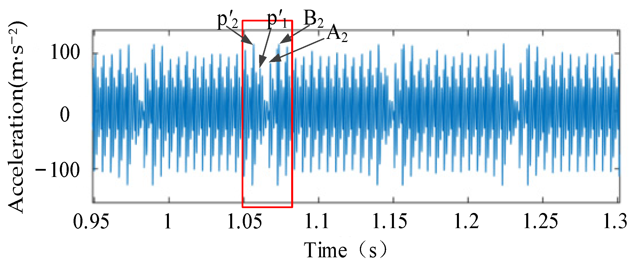
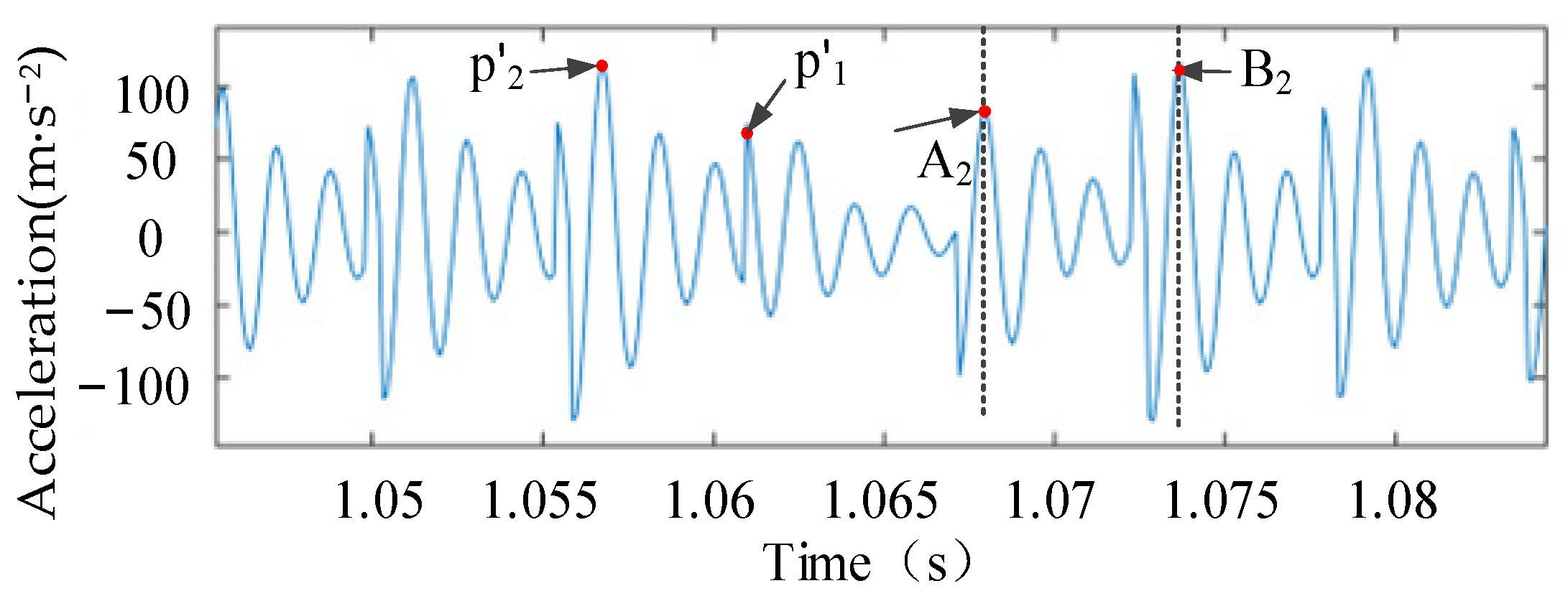
As shown in Figure 12, the maximum amplitude of the acceleration curve caused by damage to the local functional groove is approximately 100 m∙s−2. This represents a significant increase compared to the acceleration amplitude when the width of the damaged local functional groove is 0.1 mm. Additionally, there are multiple points in the figure where the acceleration peaks are approximately zero, indicating that the 14 rolling elements are compressed together at this point, while the gap between the first and last rolling elements occurs precisely at the location of the damaged local functional groove. As the width of the local functional groove damage increases, the damage along the circumferential and radial directions intensifies. Simultaneously, the number of rolling elements in the damaged local functional groove changes, causing contact between rolling elements and resulting in collisions. The collision forces generate instantaneous forces exerted by the rolling elements on the bearing inner ring; therefore, the amplitude of the inner ring acceleration increases significantly when the width of the local functional groove damage reaches 0.59 mm. To further investigate the vibration of the rolling elements entering and exiting the damaged local functional groove in the cage-less bearing, the time interval from 1.05 to 1.08 s in Figure 12 was zoomed in, as shown in Figure 13.
As shown in Figure 13, when the damage width wd = 0.59 mm, the circumferential span angle of the damaged local functional groove is calculated to be 26.28° using Equation (2). At this point, when one rolling element enters the damaged functional groove (point p′1), a vibration amplitude of 51.31 m∙s−2 is observed. When this rolling element exits the functional groove (point p′2), a vibration amplitude of 107.36 m∙s−2 is observed, indicating that the vibration amplitude during exit is greater than that during entry; When two adjacent rolling elements are completely squeezed together and exit the damaged local functional groove in succession, two acceleration peaks occur, namely points A2 and B2 in the figure, with an acceleration amplitude of approximately 105.07 m∙s−2. The patterns observed in the resulting acceleration curves are primarily due to discrete failure of the rolling elements. As the rolling elements leave the local functional groove, the rear ball impacts the front ball, increasing the front ball’s velocity. According to Equation (47), this increases the instantaneous force exerted by the front ball on the inner ring, causing the contact force between the rolling element and the inner ring to increase upon entry, which in turn leads to increased vibration of the inner ring.
A comparison of Figure 10 and Figure 13 shows that as the width wd of the local functional groove damage increases, the vibration amplitude of the bearing inner ring increases. This indicates that as the width of the local functional groove damage increases, the impact collisions between the rolling elements and the local functional groove become more pronounced when the rolling elements pass through the groove, leading to discrete failure of the rolling elements. Due to the contact collisions between rolling elements, the force Qt2 exerted by the rolling elements on the bearing inner ring increases, leading to greater contact deformation between the rolling elements and the bearing inner ring. As shown in Equation (52), this subsequently results in an increase in the radial displacement of the bearing inner ring, causing more pronounced vibration characteristics.

5.3. Frequency-Domain Analysis of Vibration Acceleration in Locally Damaged Grooved Bearings

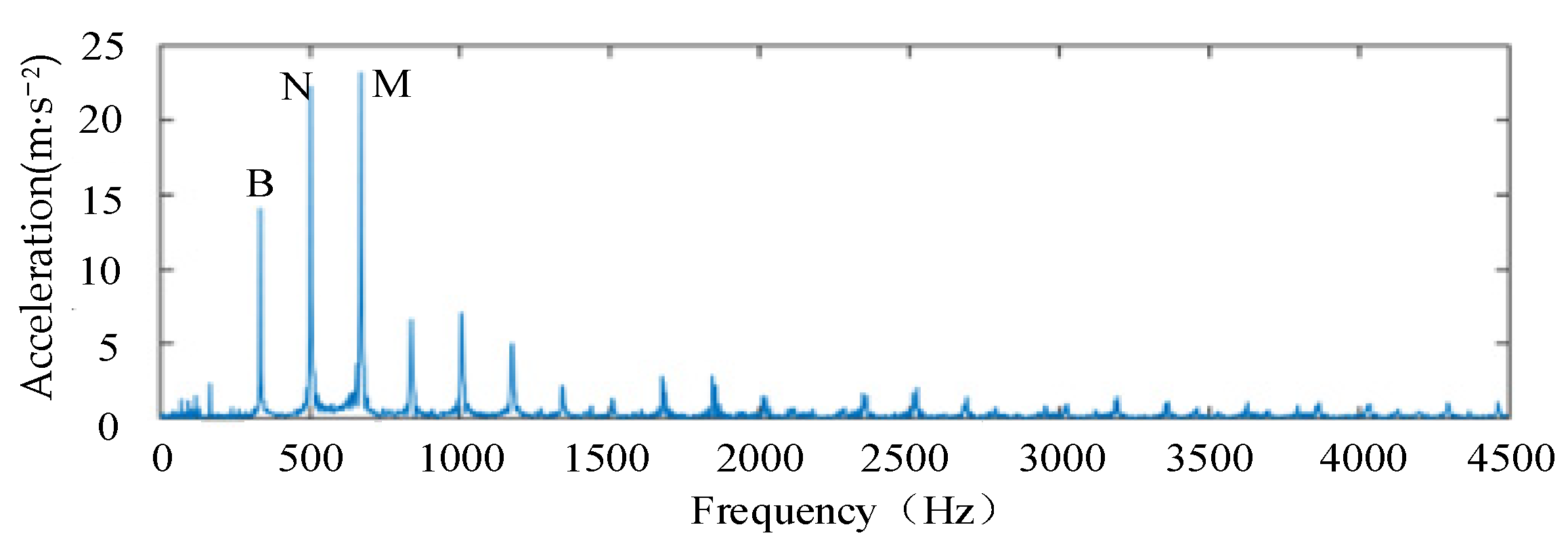
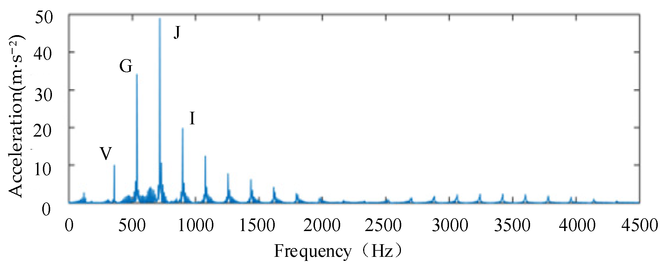
In the time domain, distinct periodic variations can be observed in the bearing vibration signal; however, the composition of the vibration signal must be analyzed in the frequency domain. Therefore, this paper combines the characteristics of the inner ring vibration signal with the Fast Fourier Transform (FFT) method to perform spectral transformation on the signal, yielding the frequency-amplitude curves shown in Figure 14 and Figure 15. The theoretical vibration frequency fdo at the corresponding rotational speed in this paper was calculated based on Reference [8].
As shown in Figure 14, when the damage width wd = 0.1 mm, the rolling elements passing through the local functional groove generate the characteristic frequency fdo = 167.998 Hz and its multiple harmonics. The frequencies at which the three acceleration values are maximized correspond to points B, N, and M, with values of 2 × 166.67 Hz, 3 × 166.67 Hz, and 4 × 166.67 Hz, respectively. where the acceleration amplitudes at the 3 × and 4 × harmonics are most pronounced. According to the research results in Reference [33], the frequency-domain vibration signals of the bearing contain unbalanced excitation caused by mass eccentricity in the bearing and rotor. This is because when rolling elements pass through a tightening section of the raceway, a time-varying displacement H is generated that first increases and then decreases. Combined with Equation (52), this results in additional deformation within the bearing’s maximum load-bearing zone, which in turn causes an increase in the radial displacement of the inner ring, leading to operational eccentricity.
As shown in Figure 15, when the damage width wd = 0.59 mm, the characteristic frequency fdo = 178.57 Hz. the frequency-amplitude curves of the vibration data show distinct characteristic frequencies at points V, G, J, and I, with values of 2 × 178.57 Hz, 3 × 178.57 Hz, 4 × 178.57 Hz, and 5 × 178.57 Hz, respectively. This is due to the increased damage width of the local functional groove. As shown in Equation (7), the effective radius of rotation between the rolling elements and the raceway decreases, leading to a reduced velocity difference between adjacent rolling elements and causing discrete failure during motion. At this point, collisions occur between adjacent rolling elements, causing the orbital speed of the rolling element that enters the local functional groove first to increase. This shortens the time interval during which the rolling element moves within the local functional groove, resulting in a higher impact frequency when the rolling element passes through the local functional groove compared to when the damage width is 0.1 mm. As the damage width increases, and based on the contact stiffness formula for the edges of the local functional groove (Equation (32)), the axial span angle of the local functional groove increases while the contact stiffness decreases. Consequently, under the action of Qt2, the bearing inner ring causes greater contact deformation between the rolling elements and the inner ring. This makes the bearing inner ring more prone to vibration, resulting in more unstable bearing operation and an increase in vibration harmonics.
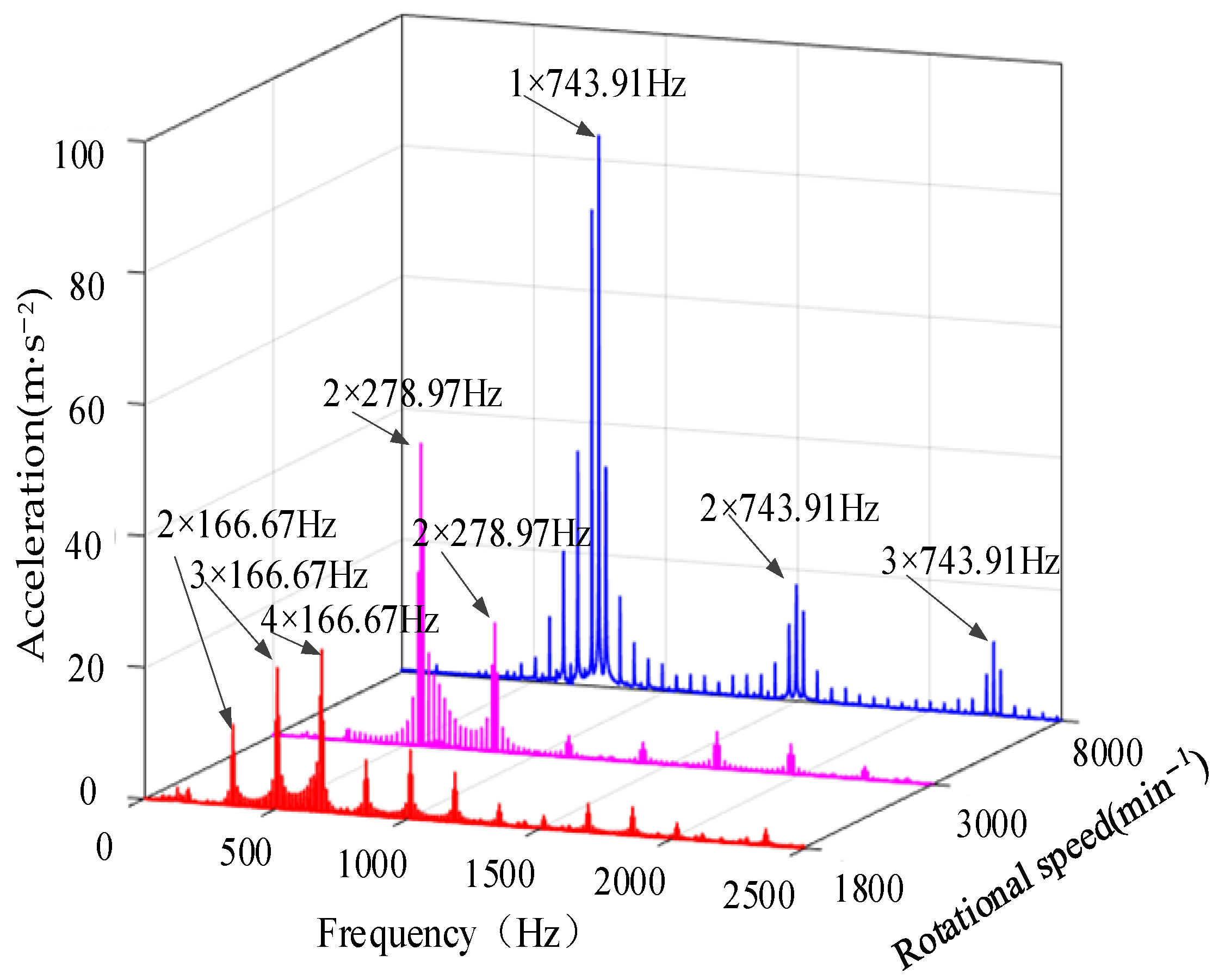
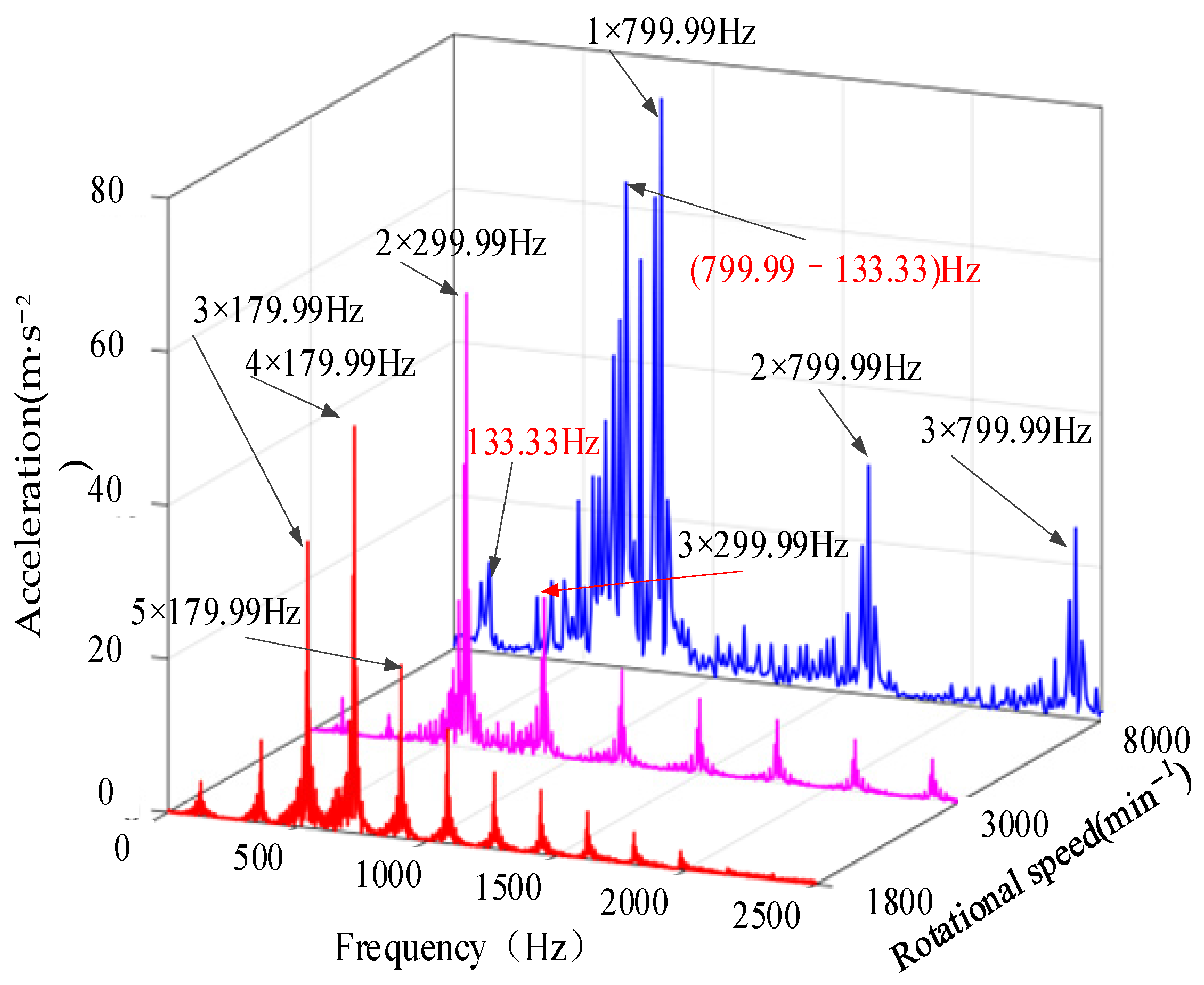
To further investigate the effects of different rotational speeds on vibration in the frequency domain, this paper conducts numerical simulations at three rotational speeds: 1800 min−1, 3000 min−1, and 8000 min−1. The vibration acceleration spectrum waterfall plots obtained for damage widths wd of 0.1 mm and 0.59 mm are shown in Figure 16 and Figure 17.
As shown in Figure 16, when the width of the localized functional groove damage is 0.1 mm, the maximum acceleration amplitudes of the bearing inner ring at rotational speeds of 1800 min−1, 3000 min−1, and 8000 min−1 are 25 m∙s−2, 47 m∙s−2, and 84 m∙s−2, respectively. The vibration acceleration amplitude of the bearing inner ring increases significantly as the rotational speed rises; The vibration frequencies corresponding to the maximum amplitudes at each speed are 4 × 166.67 Hz, 2 × 278.97 Hz, and 1 × 743.91 Hz, respectively. According to the theoretical fundamental frequencies calculated for the inner ring at each speed, these values are 167.99 Hz, 279.99 Hz, and 746.65 Hz, respectively; A comparison of the three curves in the figure with the theoretical single-frequency values reveals that the frequency peaks at each rotational speed are approximately multiples of their theoretical frequencies. Based on the preceding analysis, it is evident that when the width of the local functional groove damage is 0.1 mm, the bearing rolling elements can separate at all three rotational speeds.
As shown in Figure 17, when the width of the local functional groove damage is 0.59 mm, the maximum acceleration amplitudes of the bearing inner ring at rotational speeds of 1800 min−1, 3000 min−1, and 8000 min−1 are 49.36 m∙s−2, 53.98 m∙s−2, and 75.64 m∙s−2, respectively. The vibration acceleration amplitude of the bearing inner ring increases significantly with rising rotational speed; The vibration frequencies corresponding to the maximum amplitudes at each speed are 4 × 178.57 Hz, 2 × 299.99 Hz, and 1 × 799.99 Hz, respectively. According to the theoretical single-frequency values calculated for the inner ring at each speed, these are 167.99 Hz, 279.99 Hz, and 746.65 Hz, respectively; A comparison of the three curves in the figure with the theoretical single-frequency values reveals that the amplitude at each speed is greater than its theoretical single-frequency value. Based on the preceding analysis, this indicates that at all three speeds, the bearing vibration frequency increases due to discrete failures of the rolling elements caused by damage to the functional grooves, resulting in mutual contact and collision. Furthermore, in the frequency domain curve at 8000 min−1, a sideband at (1 × 799.99–133.33 Hz) appears in addition to the fundamental shaft frequency of 133.33 Hz. This indicates that as the damage width increases, the circumferential span angle θd of the local functional groove increases, the time-varying displacement of the rolling elements will further increase. Simultaneously, as the rotational speed rises, the misalignment of the inner ring’s rotational center worsens, ultimately causing the bearing vibration to exhibit more frequency peaks, which leads to intensified bearing vibration.
A comparison of Figure 16 and Figure 17 reveals that as the damage width wd increases, multiple harmonics appear in the vibration signal, along with frequency bands formed by the frequency-shifted modulation of the characteristic frequency. When the damage width wd = 0.59 mm, the characteristic frequency is not prominent, while the amplitudes of the 2nd and 3rd harmonics are significant; the remaining harmonics attenuate sequentially. Several equidistant side spectral lines with decreasing amplitudes are present on either side of the characteristic frequency harmonics. This is due to the discrete failure of rolling elements caused by the local functional grooves in the damaged area. The resulting impact forces create an uneven load distribution on the bearing inner ring, leading to misalignment during bearing operation and thus generating a large number of decreasing side spectral lines. Furthermore, as wd increases, the circumferential width of the local functional grooves increases, potentially causing adjacent rolling elements to enter the damaged local functional grooves simultaneously, resulting in resonance and making the bearing vibration signal components more complex.
Analysis of the time-domain and frequency-domain characteristics of the vibration signals reveals that, as the damage width wd increases, the vibration of the inner ring of the cage-less bearing becomes progressively more complex. At low rotational speeds, the amplitude of bearing vibration increases with an increase in damage width.

6. Testing of Caged Ball Bearings with Locally Damaged Grooves

6.1. Design of a Vibration Test Protocol for Grooved Ball Bearings with Localized Damage

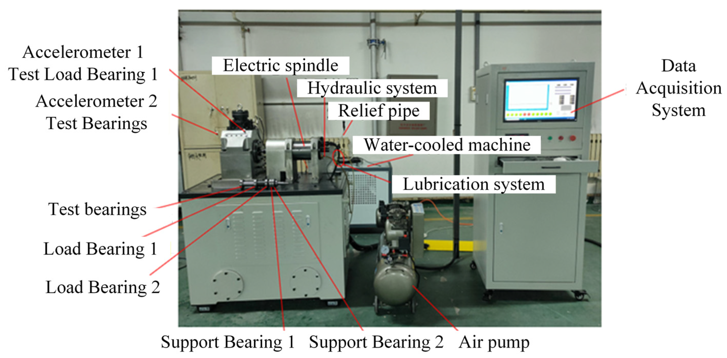
The bearing outer rings with locally machined functional grooves via electrical discharge machining were assembled into cage-less ball bearings and tested on a T10-60 bearing test machine. Vibration data for the cage-less ball bearings under various operating conditions were measured. The T10-60 bearing test machine is shown in Figure 18.
The T10-60 bearing vibration test machine primarily consists of a bearing vibration test bench, a spindle lubrication system, a data acquisition system, and a spindle cooling system. The test bearing—a cage-less, damaged partial-groove bearing—is mounted on the rotating shaft, which is located inside the test bench. Five bearings are installed on the rotating shaft: one test bearing, two loading bearings, and two support bearings. The spindle is driven by an electric motor. During the test, the bearings are lubricated with oil. Vibration data for the test bearing is collected by Accelerometer 2, while Accelerometer 1 collects data from Load Bearing 1. The lubrication system provides the power for the flow of lubricating oil to the test bearing, and water cooling is used during the test. During this test, the outer ring of the bearing remains stationary, and radial loading is applied to the bearing via a hydraulic system. Finally, the vibration data transmitted by the accelerometers is recorded and saved by the data acquisition system for subsequent analysis of the vibration data from the test bearing and the loading bearings.
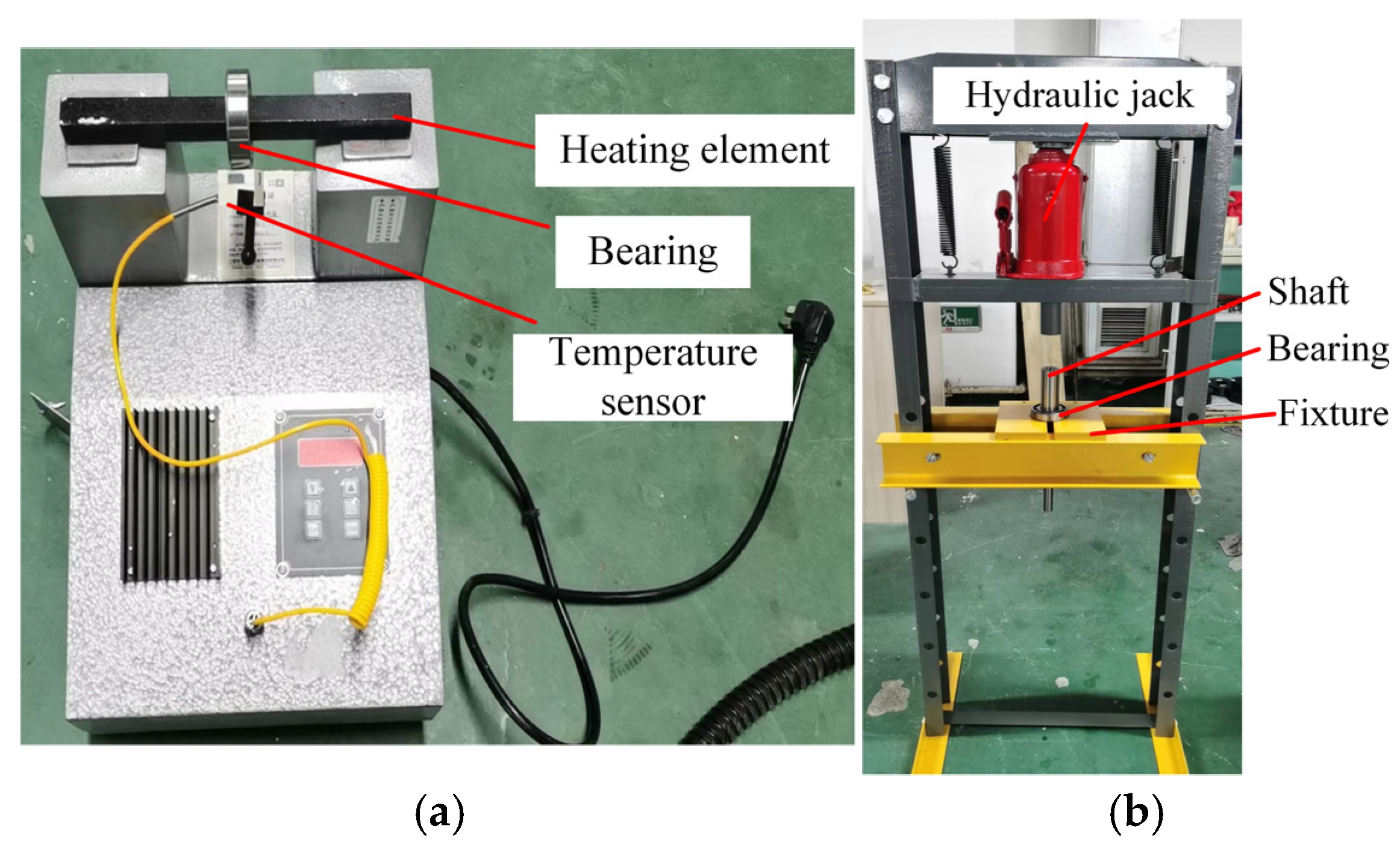
To ensure bearing installation accuracy, this bearing test also includes auxiliary equipment: a bearing electromagnetic heater and a press, shown in Figure 19.
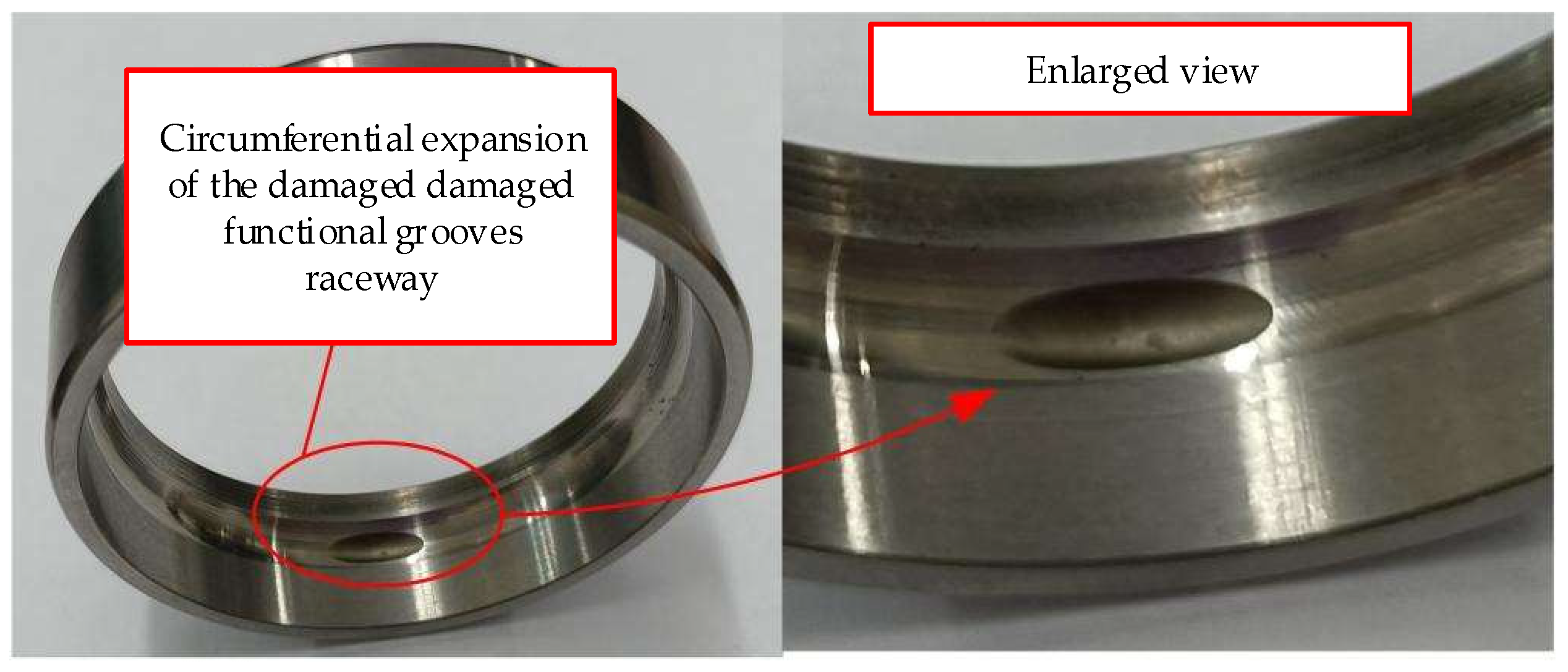
This paper will conduct the tests according to the following plan. Based on theoretical and simulation analyses, it is known that axial loads have a negligible effect on discrete rolling element failure. Therefore, the tests will only investigate the effects of different radial loads and rotational speeds on the vibration of cage-less bearings with locally damaged functional grooves. The test plan is shown in Table 4, and the EDM-damaged bearing with locally damaged functional grooves is shown in Figure 20. Due to the irreversible damage of the test bearings during the testing process and the impossibility of machining two identical test bearings, each set of tests is conducted only once, and all data are retained. Additionally, this article focuses on mechanism analysis, and the test data are only used as control data for theoretical analysis. The test itself is also a non-precision quantitative test, and the single set of valid data is sufficient to support the analysis.

6.2. Test Results and Analysis of Ball Bearings with Localized Functional Grooves

This paper presents vibration test data for bearings at different rotational speeds obtained through multi-condition vibration testing. This experiment aims to analyze the vibration time-domain characteristics of bearings under steady-state operation and compare them with theoretical results, falling within the scope of mechanism and qualitative research. The test platform has undergone vibration reduction optimization, ensuring that operating parameters remain constant throughout the process and external environmental interference is minimal, resulting in consistent vibration signals collected. Additionally, only a single set of typical data was collected under these conditions, lacking multiple sets of parallel test samples. Therefore, this paper does not analyze the data distribution patterns and error ranges.
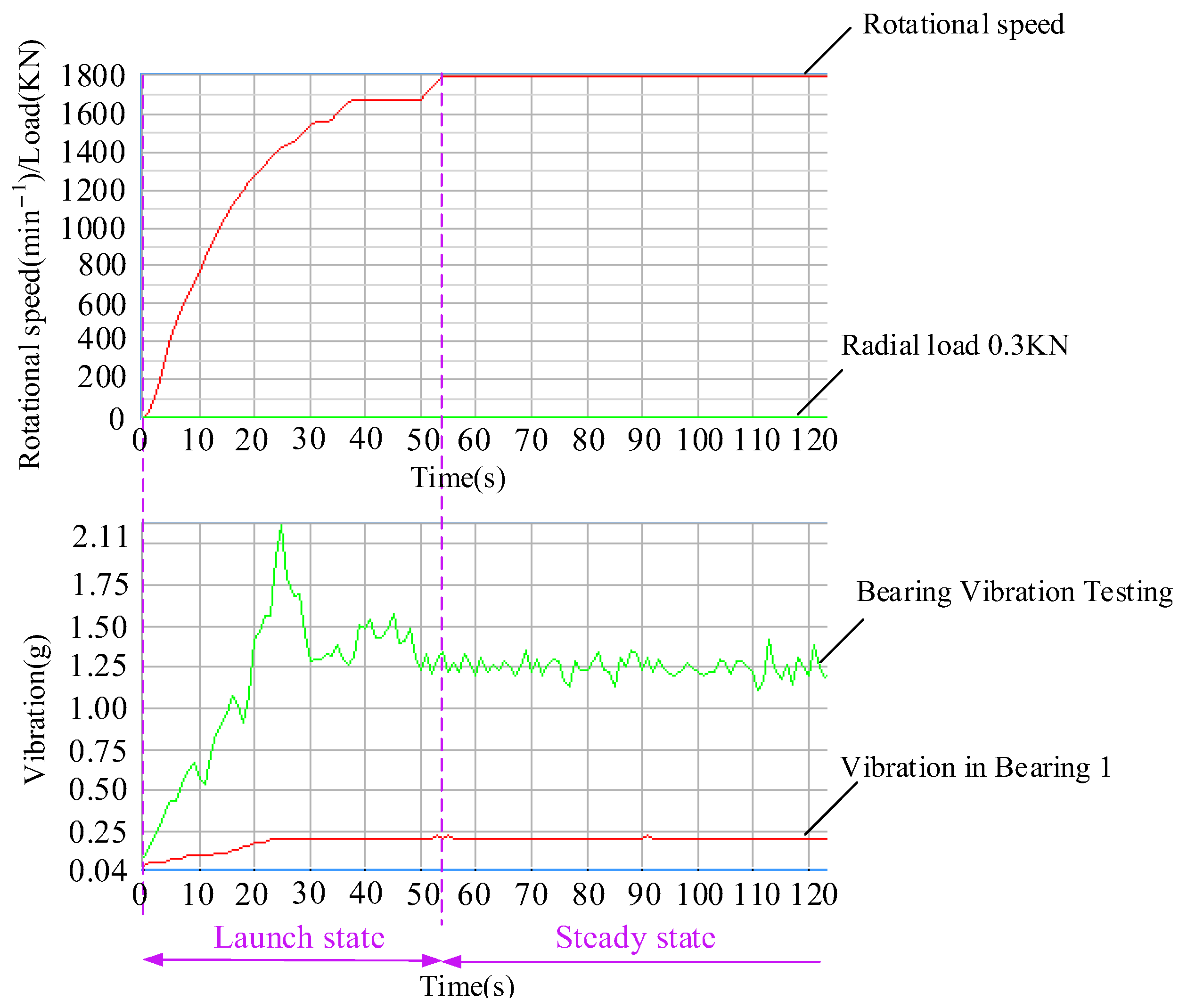
To analyze the vibration of bearings with functional grooves during the startup phase, vibration data curves for the startup phase are provided, as shown in Figure 21. As can be seen, the bearing vibration is unstable during the startup phase, resulting in significant fluctuations.
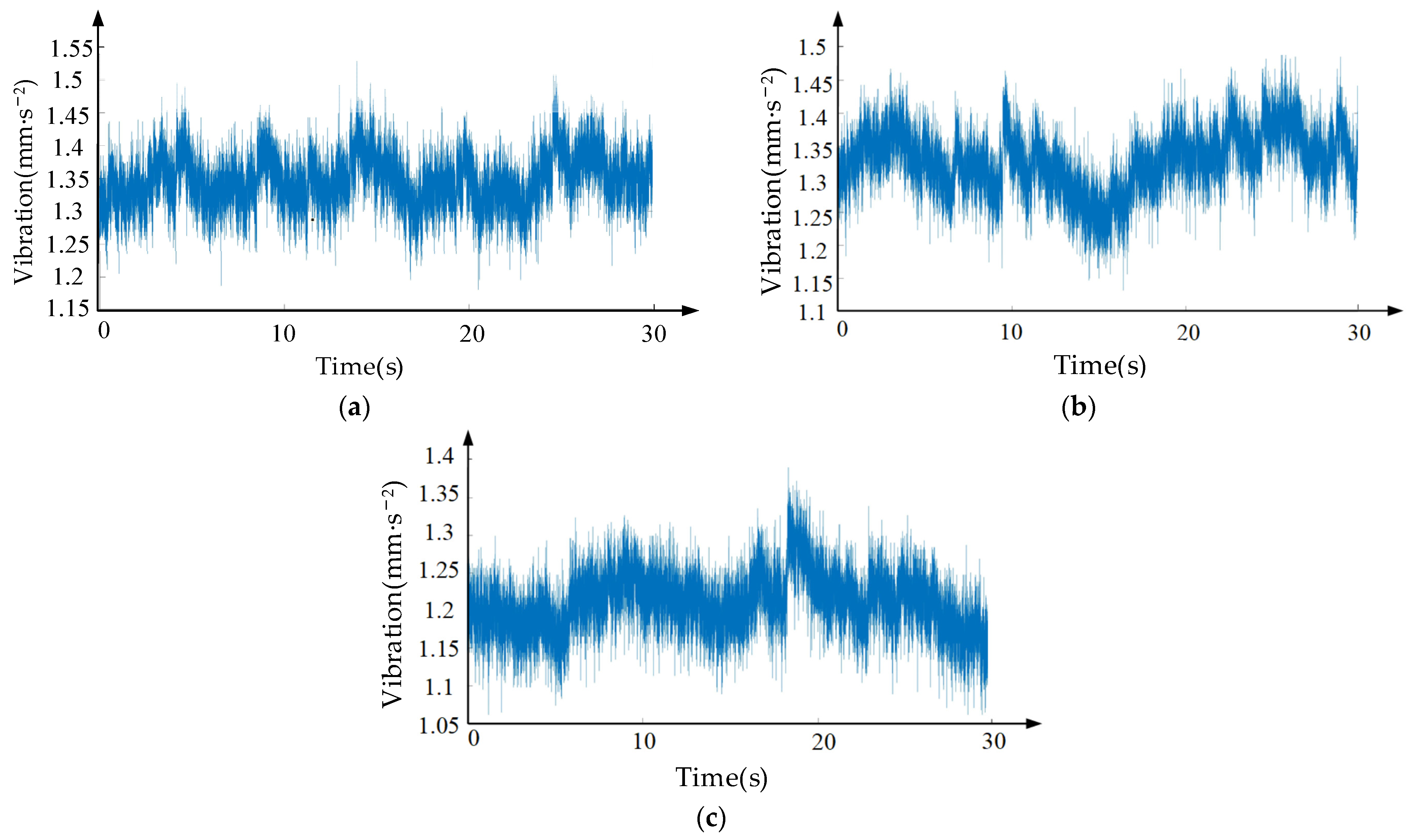
Vibration data was collected after the bearings entered steady-state operation. First, Figure 22 shows the vibration curves of cage-less ball bearings operating at a speed of 1800 min−1 under radial loads of 300 N, 500 N, and 800 N, respectively.
As shown in Figure 22, under a radial force of 300 N, the amplitude range of the vibration curve for the bearing with a functional groove in the damaged area is approximately (1.2–1.5) mm∙s−2; under a radial force of 500 N, the amplitude range of the vibration curve for the bearing with a damaged functional groove is (1.25–1.45) mm∙s−2, showing almost no change compared to the bearing under a radial force of 300 N; Under a radial force of 800 N, the amplitude range of the vibration curve for the bearing with a damaged functional groove is (1.15–1.35) mm∙s−2, which actually shows a slight decrease compared to the bearing vibrations under radial forces of 300 N and 500 N. Based on the vibration curves for the three types of loads applied to the bearing, it can be concluded that the vibration amplitude of the ball bearing with a functional groove in the damaged area and without a cage is essentially consistent with the aforementioned theoretical analysis.
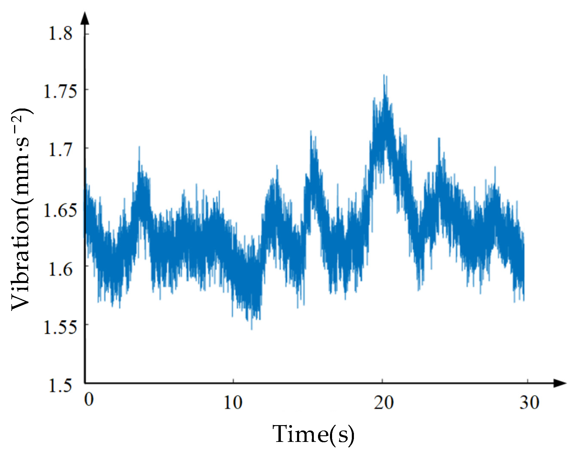
To further verify the effect of bearing rotational speed on vibration in the damaged functional groove, operating speeds of 3000 min−1 and 8000 min−1 were selected. Under the same radial load of 500 N, the measured vibration data for the bearing with the damaged functional groove are shown in Figure 23 and Figure 24, respectively.
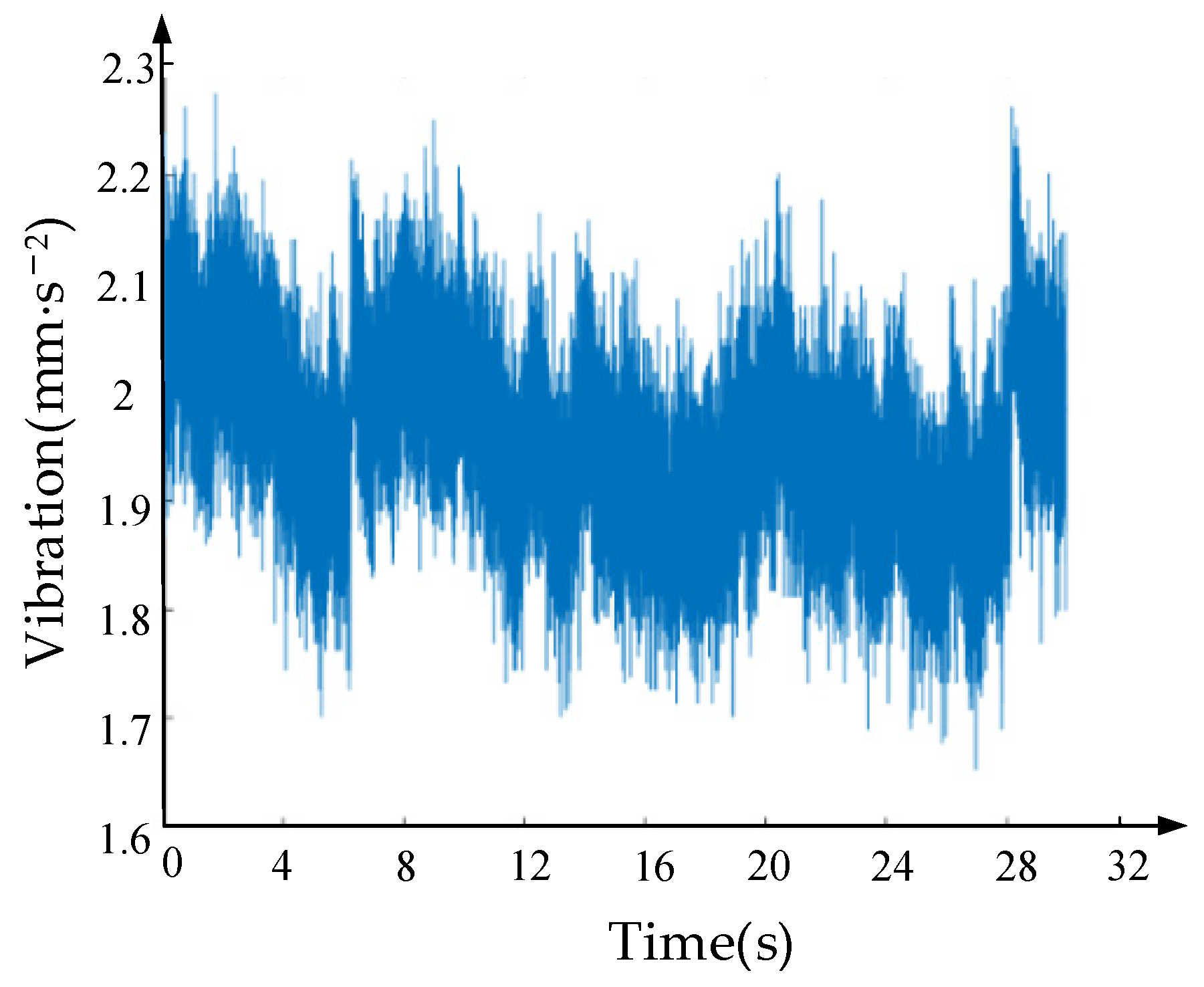
As shown in Figure 23 and Figure 24, the vibration acceleration of the bearing ranges from (1.55–1.75) mm∙s−2 at a rotational speed of 3000 min−1, and from (1.7–2.3) mm∙s−2 at 8000 min−1. It is evident that as the rotational speed increases, the vibration of the damaged local functional groove bearing intensifies. Furthermore, compared to Figure 19a, the vibration acceleration under all three load conditions shows a significant increase. This indicates that the operating speed has a clear correlation with the vibration of the damaged local functional groove bearing without a cage, thereby validating the accuracy of the theoretical vibration solutions obtained at different rotational speeds as discussed earlier.

7. Conclusions

This paper addresses the issue of bearing vibration caused by damage to the functional grooves in caged ball bearings. It analyzes the impact of damaged functional grooves on the dynamic characteristics of rolling elements, establishes a vibration equation for caged ball bearings with damaged functional grooves, and investigates the vibration of such bearings through numerical solutions, simulation analysis, and experiments. The specific conclusions are as follows:
  • The motion of rolling elements over the damaged groove was analyzed, and relationships were established between the groove damage width and the groove’s circumferential and axial spans, as well as the effective radius of gyration and discrete spacing of the rolling elements. The damage width (wd) was determined as the parameter characterizing the severity of groove damage; Based on this, an equation relating the relative velocity of adjacent rolling elements passing through the damaged groove to the damage width was established. The critical ranges for damage width (wd) and damage depth (hd), as well as the minimum velocity difference, were obtained for discrete failure collisions of rolling elements in the damaged groove. Based on the motion and collision analysis of rolling elements in the damaged groove, time-varying displacement and contact stiffness models were constructed, and an instantaneous force model for the inner ring during collisions was derived.
  • The displacement of the inner ring of the bearing with a damaged functional groove was analyzed. Combining this with contact analysis of the inner ring displacement under bearing load, a differential equation for bearing vibration was established. Based on the rolling element relative velocity equation, the critical value of the damage width wd for the functional groove during discrete rolling element failure was determined to be 0.5868 mm. Damage widths of 0.1 mm and 0.59 mm were then substituted into the bearing vibration equation. Using MATLAB programming, the vibration equation was solved and analyzed, yielding the time-domain vibration acceleration amplitude patterns at a rotational speed of 1800 min−1, as well as the vibration characteristics in the frequency domain acceleration and phase space at rotational speeds of 1800 min−1, 3000 min−1, and 8000 min−1, as well as the vibration patterns in phase space as the damage width of the functional groove varies.
  • A vibration simulation model for ball bearings with damage-inducing grooves and no cage was designed, yielding the variation patterns of rolling element velocity, discrete spacing between rolling elements, and bearing vibration acceleration. A bearing vibration test plan was developed, and variable-load and variable-speed vibration tests were conducted on ball bearings with damage-inducing grooves and no cage. The results indicate that the vibration amplitude of the ball bearings with damaged functional grooves does not vary significantly with load, but increases with rising rotational speed, thereby validating the accuracy of the aforementioned theoretical analysis of bearing vibration.

8. Discussions

  • Unlike the ideal rectangular defects prepared by electric discharge machining in the experiment, under actual working conditions, the edges of the bearing’s variable diameter raceway undergo significant plastic deformation due to long-term friction and compression, ultimately forming a smooth damage morphology with a gradual transition zone. When the rolling elements pass through this transition zone, the contact force and contact stiffness undergo continuous changes rather than abrupt transitions. The surface material extension and compaction effects induced by plastic deformation further buffer the mechanical impact, effectively reducing not only the peak amplitude of the impact pulse but also extending the duration of the pulse action. The originally steep and sharp impact signal is significantly smoothed, and the impact characteristics are substantially attenuated.
It can be seen that the artificial rectangular defects with sharp edges and corners cannot reproduce the true morphology of bearing damage in engineering scenarios. This morphological difference fundamentally alters the excitation characteristics of vibration signals. Therefore, the vibration response and fault characteristics obtained based on ideal defects created by electric discharge machining cannot fully reflect the actual operating state of in-service bearings, which is also the main limitation of this study.
2.
All experiments and analyses in this work are implemented under dry friction conditions for functional groove damage of cage-less ball bearings. Since bearings in practical engineering generally operate with lubrication, which greatly affects interfacial friction and damage evolution, the damage behaviors of functional grooves under lubricated environments remain to be studied in future work.

Author Contributions

Conceptualization, E.Z.; methodology, J.Z.; software, E.Z.; validation, L.F., H.Q. and H.Z.; data curation, E.Z.; writing—original draft preparation, E.Z.; writing—review and editing, Y.Z. and L.F.; visualization, Y.Z.; project administration, J.Z.; funding acquisition, J.Z. All authors have read and agreed to the published version of the manuscript.

Funding

This work was financially supported by the Jilin Provincial Department of Education Scientific Research Project (JJKH20251825KJ) and Jilin Tiedao University Doctoral Research Start-up Fund.

Data Availability Statement

The original contributions presented in this study are included in the article. Further inquiries can be directed to the corresponding author.

Conflicts of Interest

Authors Jingwei Zhang and Enwen Zhou are employed by the company Goertek Inc. Postdoctoral Research Station, Goertek Co., Ltd. The remaining authors declare that the research was conducted in the absence of any commercial or financial relationships that could be construed as a potential conflict of interest.

References

  1. McFadden, P.D.; Smith, J.D. Model for the Vibration Produced by a Single Point Defect in a Rolling Element Bearing. J. Sound Vib. 1984, 96, 69–82. [Google Scholar] [CrossRef]
  2. Chang, B.Q.; Yan, C.F.; Yuan, H.; Kang, J.X.; Wang, K.; Wu, L.X. Dynamic Modeling for Rolling Bearings under Multi-event Excitation. J. Vib. Shock 2018, 37, 16–24. [Google Scholar] [CrossRef]
  3. Zhang, Z.M.; Lu, W.X.; Yang, S.Z.; Zhang, Y.T. A Model for the Vibration Produced by Local Faults in Roller Bearing and Its Application. J. Huazhong Univ. Sci. Technol. 1997, 3, 51–54. [Google Scholar] [CrossRef]
  4. Zhang, Y.Q. Nonlinear Dynamic Characteristics and Stability Analysis of Gyroscope Rotor System. Doctoral Thesis, Xidian University, Xi’an, China, 2011. [Google Scholar]
  5. Chen, G. Dynamic Analysis of Rolling Bearing Fault in Rotor-Rolling Bearing-Casing Coupling System. J. Vib. Eng. 2008, 21, 577–587. [Google Scholar] [CrossRef]
  6. Fan, J.; Cui, W.; Han, Q. Vibration Signal Modeling of a Localized Defective Rolling Bearing Under Unbalanced Force Excitations. J. Vibroeng. 2017, 19, 5009–5019. [Google Scholar] [CrossRef]
  7. Jiang, Y.; Huang, W.; Luo, J.; Wang, W. An Improved Dynamic Model of Defective Bearings Considering the Three-Dimensional Geometric Relationship Between the Rolling Element and Defect Area. Mech. Syst. Signal Process. 2019, 129, 694–716. [Google Scholar] [CrossRef]
  8. Gao, X.H. Dynamic Modeling and Nonlinear Vibration Characteristic of Rolling Ball Bearing with Multiple Defects on Raceways. Master’s Thesis, Lanzhou University of Technology, Lanzhou, China, 2021. [Google Scholar]
  9. Guan, Z.Z.; Zheng, H.Q.; Wang, Y.G.; Yang, J. Dynamic Modeling and Simulation of Rolling Bearing with Localized Damage Fault. J. Vib. Meas. Diagn. 2012, 32, 950–955. [Google Scholar] [CrossRef]
  10. Behzad, M.; Mi, A.R.B.A.; Mba, D. A New Model for Estimating Vibrations Generated in the Defective Rolling Element Bearings. J. Vib. Acoust. 2011, 133, 041011-1. [Google Scholar] [CrossRef]
  11. Liu, J. Nonlinear Excitation Mechanism and Modeling Research of Rolling Bearing Defects. Doctoral Thesis, Chongqing University, Chongqing, China, 2014. [Google Scholar]
  12. Khanam, S.; Dutt, J.K.; Tandon, N. Impact Force Based Model for Bearing Local Fault Identification. J. Vib. Acoust. 2015, 137, 051002. [Google Scholar] [CrossRef]
  13. Huang, W.T.; Dong, Z.Z.; Kong, F.C. Vibration Model of Rolling Element Bearing with Inner Race Defect Considering the Impact Force. J. Vib. Shock 2016, 35, 121–126+159. [Google Scholar] [CrossRef]
  14. Luo, M.L.; Guo, Y.; Wu, X. Dynamic Modeling of the Dual-Impulse Behavior Produced by A Spall On the Outer Race of A Ball Bearing Considering Impact Forces. J. Vib. Shock 2019, 38, 7. [Google Scholar] [CrossRef]
  15. Liu, J.; Tang, C.; Shao, Y. An Innovative Dynamic Model for Vibration Analysis of a Flexible Roller Bearing. Mech. Mach. Theory 2019, 135, 27–39. [Google Scholar] [CrossRef]
  16. Yang, Y.; Ouyang, H.; Wu, X.; Jin, Y.; Cao, D.Q. Bending-torsional Coupled Vibration of a Rotor-bearing-system Due to Blade-casing Rub in Presence of Non-uniform Initial Gap. Mech. Mach. Theory 2019, 140, 170–193. [Google Scholar] [CrossRef]
  17. Zheng, L.; Xiang, Y.; Sheng, C. Nonlinear Dynamic Modeling and Vibration Analysis of Faulty Rolling Bearing Based on Collision Impact. J. Comput. Nonlinear Dyn. 2021, 16, 061001. [Google Scholar] [CrossRef]
  18. Cui, L.; Jin, Z.; Huang, J.; Wang, H. Fault Severity Classification and Size Estimation for Ball Bearings Based on Vibration Mechanism. IEEE Access 2019, 7, 56107–56116. [Google Scholar] [CrossRef]
  19. Liu, J.; Wu, H.; Shao, Y. A Theoretical Study on Vibrations of a Ball Bearing Caused by a Dent on the Races. Eng. Fail. Anal. 2018, 100, 220–229. [Google Scholar] [CrossRef]
  20. Parmar, V.; Saran, V.H.; Harsha, S.P. Effect of Dynamic Misalignment on the Vibration Response, Trajectory Followed and Defect-depth Achieved by the Rolling-elements in a Double-row Spherical Rolling-element Bearing. Mech. Mach. Theory 2021, 162, 104366. [Google Scholar] [CrossRef]
  21. Shah, D.S.; Patel, V.N. A Dynamic Model for Vibration Studies of Dry and Lubricated Deep Groove Ball Bearings Considering Local Defects on Races. Measurement 2019, 137, 535–555. [Google Scholar] [CrossRef]
  22. Xi, S.; Cao, H.; Chen, X. Dynamic Modeling of Spindle Bearing System and Vibration Response Investigation. Mech. Syst. Signal Process. 2019, 114, 486–511. [Google Scholar] [CrossRef]
  23. Yang, Y.; Yang, W.; Jiang, D. Simulation and Experimental Analysis of Rolling Element Bearing Fault in Rotor-bearing-casing System. Eng. Fail. Anal. 2018, 92, 205–221. [Google Scholar] [CrossRef]
  24. Liu, J. A Dynamic Modelling Method of a Rotor-roller Bearing-housing System with a Localized Fault Including the Additional Excitation Zone. J. Sound Vib. 2020, 469, 115144. [Google Scholar] [CrossRef]
  25. Liu, Y.Q.; Chen, Z.G.; Wang, K.Y.; Zhai, W.M. Surface Wear Evolution of Traction Motor Bearings in Vibration Environment of a Locomotive during Operation. Sci. China Technol. Sci. 2022, 65, 920–931. [Google Scholar] [CrossRef]
  26. Zhao, Y.L.; Zhang, X.N.; Qin, S. Design and Simulation Analysis of Variable Speed Surface of Cage-free Bearing. J. Harbin Univ. Sci. Technol. 2021, 26, 33–39. [Google Scholar] [CrossRef]
  27. Zhong, B.L.; Huang, R. Mechanical Fault Diagnosis; China Machine Press: Beijing, China, 2002; pp. 156–157. [Google Scholar]
  28. Zhao, Y.L.; Hou, X.X.; Bao, Y.D.; Pan, C.Y. Contact Dynamic Measurement Dynamics of Bearing Cylindrical Roller Diamete. Chin. J. Sci. Instrum. 2019, 40, 18–26. [Google Scholar] [CrossRef]
  29. Ju, Z.L. Calculation of Torsion Springs. J. Vib. Shock 1997, 2, 26–29+97. [Google Scholar] [CrossRef]
  30. Yao, X. Collision Vibration Analysis of Aeroengine Rolling Bearing Cage. Master’s Thesis, Harbin Institute of Technology, Harbin, China, 2014. [Google Scholar]
  31. Johnson, K.L.; Xu, B.Y.; Luo, X.F.; Liu, X.S. Contact Mechanics Trans.; Higher Education Press: Beijing, China, 1992. [Google Scholar]
  32. Xia, D. Dynamic Parameter Identification and Software Design of Space Robots. Master’s Thesis, Harbin Institute of Technology, Harbin, China, 2009. [Google Scholar]
  33. Li, M.; Li, Z.G. Nonlinear Vibration of Rotor-Bearing System Under Holonomic Constraints; Science Press: Beijing, China, 2014. [Google Scholar]
Figure 1. Schematic diagram of cage free ball bearing with damaged variable raceway. (a) Schematic diagram of the local functional groove structure; (b) Schematic diagram of contact between rolling elements No. 2.
Lubricants 14 00248 g001
Figure 2. Motion diagram of rolling body in damaged raceway.
Lubricants 14 00248 g002
Figure 3. Time-varying displacement of damaged raceway rolling body.
Lubricants 14 00248 g003
Figure 4. Contact stiffness of inner and outer ring of variable radius raceway.
Lubricants 14 00248 g004
Figure 5. Force analysis of bearing rolling element.
Lubricants 14 00248 g005
Figure 6. Displacement of bearing inner ring. (a) Axial displacement of the bearing inner ring; (b) Radial displacement of the bearing inner ring.
Lubricants 14 00248 g006
Figure 7. Bearing vibration model.
Lubricants 14 00248 g007
Figure 8. Relation diagram of bearing damage width and discrete spacing.
Lubricants 14 00248 g008
Figure 9. Solution flow chart of bearing vibration equation.
Lubricants 14 00248 g009
Figure 10. Damage width 0.1 mm bearing vibration acceleration.
Lubricants 14 00248 g010
Figure 11. Magnified view of local vibration with damage width of 0.1 mm.
Lubricants 14 00248 g011
Figure 12. Damage width 0.59 mm bearing vibration acceleration.
Lubricants 14 00248 g012
Figure 13. Magnified view of local vibration with damage width of 0.59 mm.
Lubricants 14 00248 g013
Figure 14. Vibration frequency domain diagram with damage width of 0.1 mm.
Lubricants 14 00248 g014
Figure 15. Frequency domain diagram of vibration with damage width of 0.59 mm.
Lubricants 14 00248 g015
Figure 16. Frequency domain waterfall diagram with damage width of 0.1 mm.
Lubricants 14 00248 g016
Figure 17. Frequency domain waterfall diagram with damage width of 0.59 mm.
Lubricants 14 00248 g017
Figure 18. T10-60 bearing vibration testing machine.
Lubricants 14 00248 g018
Figure 19. Bearing electromagnetic heater and press. (a) Bearing electromagnetic heater; (b) Press.
Lubricants 14 00248 g019
Figure 20. Schematic diagram of variable radius raceway damage.
Lubricants 14 00248 g020
Figure 21. Relationship between vibration and speed during start-up.
Lubricants 14 00248 g021
Figure 22. Bearing vibration acceleration test curve at speed of 1800 min−1. (a) Bearing vibration acceleration with a radial force of 300 N; (b) Bearing vibration acceleration with a radial force of 500 N; (c) Bearing vibration acceleration with a radial force of 800 N.
Lubricants 14 00248 g022
Figure 23. Bearing vibration acceleration test curve at speed of 3000 min−1.
Lubricants 14 00248 g023
Figure 24. Bearing vibration acceleration test curve at speed of 8000 min−1.
Lubricants 14 00248 g024
Table 1. Basic parameters of damaged variable radius raceway.
ParametersParameters Value
Bearing inner diameter di (mm)30
Bearing outer diameter do (mm)62
Bearing width B (mm)16
Pitch circle diameter dm (mm)46
Rolling element diameter Dw (mm)9.525
Length of local functional groove L (mm)11.5
Width of local functional groove W (mm)3.5
Damage width wd (mm)0.1 (0.59)
Bearing contact angle15
Number of rolling elements N14
Table 2. Basic parameters of cage-less bearings.
Inner and Outer RingsParametersRolling ElementParameters
Modulus of elasticity of bearing steel (MPa)2.08 × 10⁵Modulus of elasticity of bearing steel (MPa)2.08 × 10⁵
Poisson’s ratio of bearing steel0.3Poisson’s ratio of bearing steel0.3
Density of bearing steel (kg∙mm−3)7.85 × 10⁻⁶Density of bearing steel (kg∙mm−3)7.85 × 10⁻⁶
Table 3. Initial parameters of vibration differential equation.
Initial ParametersParameters Value
Load in the Y direction, Fr (N)500
Load in the Z direction, Fa (N)200
Displacement in the X direction, x (m)10−6
Displacement in the Y direction, y (m)10−4
Displacement in the Z direction, z (m)10−6
Velocity in the X direction, x (m∙s−1)0
Velocity in the Y direction, y (m∙s−1)0
Velocity in the Z direction, z (m∙s−1)0
Table 4. Test program of cage free ball bearings.
Rotational Speed1800 min−13000 min−18000 min−1
Radial load300 N500 N800 N500 N500 N
Lubrication methodOil lubrication
Mounting methodThe local functional groove is located at the lowest point of the load-bearing area
Location of the damage-induced functional grooveouter ring
Disclaimer/Publisher’s Note: The statements, opinions and data contained in all publications are solely those of the individual author(s) and contributor(s) and not of MDPI and/or the editor(s). MDPI and/or the editor(s) disclaim responsibility for any injury to people or property resulting from any ideas, methods, instructions or products referred to in the content.