Article

Wear of a Ceramic-on-Ceramic Hip Resurfacing Under Activities of Daily Function


by
Raelene M. Cowie
1,
Danielle de Villiers
2,
Simon N. Collins
2 and
Louise M. Jennings
1,*
1
Institute of Medical and Biological Engineering, School of Mechanical Engineering, University of Leeds, Leeds LS2 9JT, UK
2
MatOrtho Ltd., Leatherhead KT22 7BA, UK
*
Author to whom correspondence should be addressed.
Lubricants 2026, 14(6), 219; https://doi.org/10.3390/lubricants14060219
Submission received: 26 February 2026 / Revised: 19 May 2026 / Accepted: 25 May 2026 / Published: 28 May 2026
(This article belongs to the Special Issue Biotribology and Orthopedics: Shaping Safer Postoperative Pathways)

Abstract

Hip resurfacing is a bone-conserving alternative to total hip replacement particularly suited to younger or more active patients with good bone stock. Historical issues with metal-on-metal hip resurfacing devices have led to investigations of new materials. In this study, the wear of a BIOLOX delta ceramic-on-ceramic hip resurfacing under a range of activities of daily function was investigated in an experimental simulation model. Under a standard walking gait, increased frequency, and stop–dwell–start conditions, the wear of the ceramic head and cup was low and at the limit of the sensitivity of the measurement technique used (<0.1 mm3/million cycles). Only when tested under a jogging-like protocol with higher loading (maximum 4.5 kN) coupled with higher frequency (1.25 Hz), under both continuous running and stop–dwell–start conditions, was wear measurable but still low, with a mean <0.15 mm3/million cycles. At the conclusion of the study, no wear scar was visible on any components and no changes in the surface roughness of the implants was measured. This short-term, pre-clinical study showed low wear of BIOLOX delta ceramic-on-ceramic hip resurfacings when evaluated under a range of activities of daily living and that this material combination has potential for the next generation of large-diameter hip bearings.

1. Introduction

Hip resurfacing presents several potential advantages over conventional total hip replacements, including the conservation of femoral bone, lower dislocation rates, greater range of motion, more physiological biomechanics, and an increased rate of return to high-demand activities [1,2]. However, only 2.6% of all hip arthroplasties in the National Joint Registry are resurfacings and these are most commonly implanted in younger (mean age 54 years old) active men (75%) [3]. The majority of implanted hip resurfacing devices are manufactured from cobalt chrome. When optimally positioned, these implants can perform well tribologically with low wear, particularly under a standard walking gait cycle [4]. However, both surgical and design factors can influence metal-on-metal hip resurfacing implant wear. For example, during surgery, rotational and/or translational mal-positioning of the components can subsequently result in contact between the head and rim of the cup (edge loading), which may accelerate wear. Further, there is the effect of hip resurfacing design, with sub-hemispherical cups being tribologically more sensitive to surgical mal-positioning than hemispherical cups [4]. A consequence of an increase in wear may be adverse biological reactions of the body to cobalt and chromium debris originating from the metal-on-metal bearing, leading to failure [4,5,6,7]. This has led to a decrease in the number of implantations from ~6000 per annum in 2007 to ~800 per year in 2024 [3]. Given the potential benefits of the large diameter hip resurfacing design but the desire to move away from metal-on-metal articulations, other bearing materials have been explored, including metal-on-polyethylene [8,9] and ceramic-on-ceramic designs [10,11,12].
The use of ceramic-on-ceramic bearings in joint replacement would minimise the implantation of metal in the body and the subsequent release of metal ions [13]. Ceramics have been widely used as a bearing material in ceramic-on-ceramic and ceramic-on-polyethylene total hip replacements for >20 years and have demonstrated low wear rates, excellent biocompatibility, and good survivorship (<5% revision rate at 20 years [3]), both in laboratory studies [14,15,16] and in vivo [17]. Whilst the first generation of alumina ceramic-on-ceramic hip implants exhibited low wear compared to conventional hip implant materials, they were associated with high fracture rates [18]. The ceramic material of interest in this study was BIOLOX delta (CeramTec, Plochingen, Germany). This fourth-generation, zirconia-toughened alumina ceramic has a much improved fracture resistance compared to first-generation ceramics, whilst retaining the low-wear properties [18]. Clinically, the revision rates of fourth-generation ceramics have been low (survivorship > 98% at 12 years [19,20]), with very low fracture rates (2 fractures of cups and no head fractures in a cohort of 6654 fourth-generation ceramic implants [21]). The improved mechanical properties allow for the manufacture of thinner components, such as the head and liner of a ceramic-on-ceramic resurfacing device [18].
In a study by de Villiers and Collins [10], large-diameter BIOLOX delta ceramic–on-ceramic hip resurfacings were shown to have comparable wear rates to smaller-diameter total hip replacements, with 1 mm3 of wear over the duration of a 5 million cycle wear study. In addition, when tested under edge-loading conditions, although wear of the implants increased, the wear rate remained low and a stripe, typical of the edge-loading wear mechanism on ceramic-on-ceramic bearings, was visible on the heads [22,23]. Whilst total hip replacements using a self-mating BIOLOX delta bearing couple have been widely investigated, only minimal investigations of hip resurfacings have been carried out [10,24], and given the low implantation rates, current clinical data related to hip resurfacing survival need to be treated with caution [3,12].
Prior to clinical adoption, it is important to evaluate and understand the wear of joint replacements under a range of conditions—in particular, the more demanding conditions under which an implant intended for use in younger patients is likely to be subjected [25]. For the evaluation of hard-on-hard bearing materials, guides from the ASTM [26,27] recommend amongst other studies the evaluation of wear with different loading parameters such as higher frequencies and higher peak loads such as those which may occur during jogging. It is also recommended to investigate stop–dwell–start (SDS) protocols that replicate the typical movement of a patient [28]. The aim of this study was to investigate the wear of a ceramic-on-ceramic hip resurfacing under such activities of daily function.

2. Materials and Methods

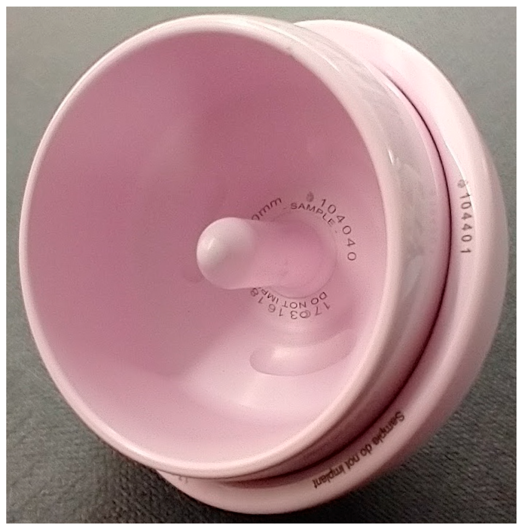
Six BIOLOX delta (Zirconia Toughened Alumina) (CeramTec, Plochingen, Germany) 40/46 mm ceramic-on-ceramic hip resurfacing devices, ReCerf®, MatOrtho, Leatherhead, UK (Figure 1), were investigated [10]. This is the smallest implant size in the range. In a previous study no significant difference in wear between the largest and smallest implant sizes of this ceramic-on-ceramic hip resurfacing system under a standard walking gait (ISO 14242-1 [29]) was observed over 5 million cycles (MC) of wear simulation [10]. The smaller implant size also more closely matched the capabilities of the simulator used in this study.
The heads were set up with respect to their paired cups with the centre of the head and cup coincident with the flexion/extension, abduction/adduction, and internal rotation axes of the simulator. The heads were supported by a poly (methyl methacrylate) (PMMA) casting of the inner surface of the implant; this was mounted on a vertical spigot within the simulator; the cups were held in fixtures using a Delrin ring to clamp the components in place. An in vivo inclination angle of 45° was replicated in the set up. To enable the implants to be removed from fixtures for gravimetric analysis, the fixation surface of the tested implants differed from that of the clinical parts. The heads, which are intended to be cemented to the bone, have two circumferential grooves and three internal pockets to prevent rotation. In the study test parts, the circumferential grooves were absent to allow the head to be removed from the cement mantle but the three cement pockets which prevent rotation of the head on the PMMA cement mantle were retained. The cups are intended to fix directly to the bone via a rough plasma sprayed titanium coating overlayed with hydroxyapatite. This coating was absent for the purpose of experimental simulation with fixation of the cup in the fixtures provided by the clamping force of the Delrin locking ring. This approach is similar to that used and described by de Villiers and Collins [10] in previous wear studies of this hip resurfacing implant. The pairing and orientation of the head and cup were maintained for the duration of the study. The mean radial clearance (±95% confidence limits) between the heads and cups was 0.077 ± 0.016 mm.
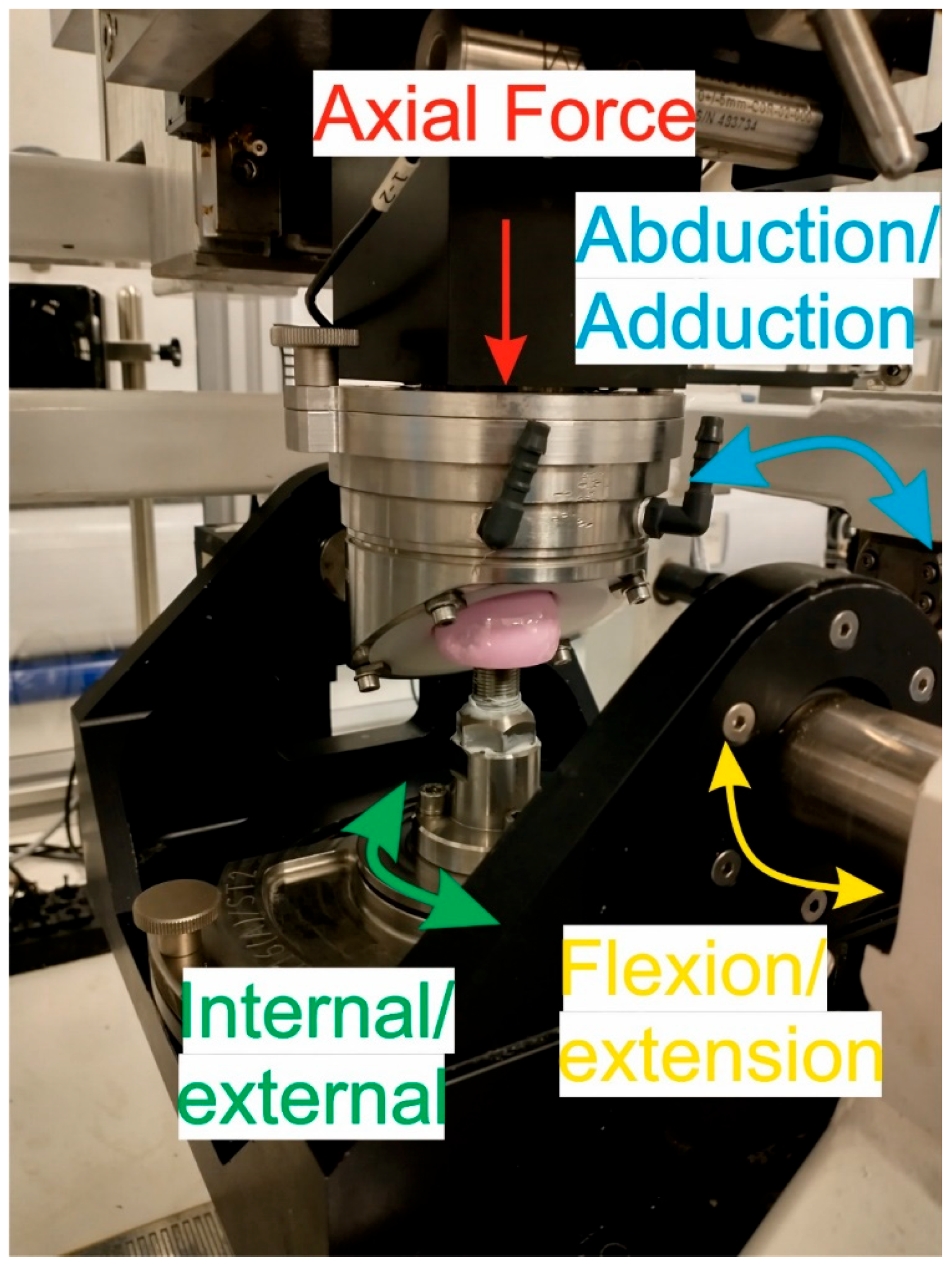
The simulation was carried out using two 3-station ProSim hip simulators (Simulation Solutions, Stockport, UK), EM16 A and B (Figure 2). These multi-station, multi-axis machines are capable of simulating a gait cycle as defined by ISO 14242-1 but can also deliver a larger range of loading and motion to replicate activities of daily living. In the simulator, the joint was set up anatomically with the cup mounted superiorly to the head. All motions (flexion/extension, abduction/adduction, and internal/external rotation) were applied to the head and the axial load was applied vertically through the cup, which was allowed to translate in a medial–lateral and anterior–posterior direction to align with the head. All axes were electromechanically driven using a combination of motors, drives, and gearboxes. The angular displacements were measured using encoders in the motors and the forces measured using a 6-axis load cell mounted above the cup. The flexion/extension and abduction/adduction axes were linked, with a single motor providing the motion for all 3 stations; the internal/external motion was controlled by individual motors for each station. The axial force was delivered and controlled by a single motor with all 3 stations linked by belts and pulleys; however, the force applied to each hip device was measured individually to ensure the load applied was within a given tolerance. Calibration of the simulator was carried out prior to use.
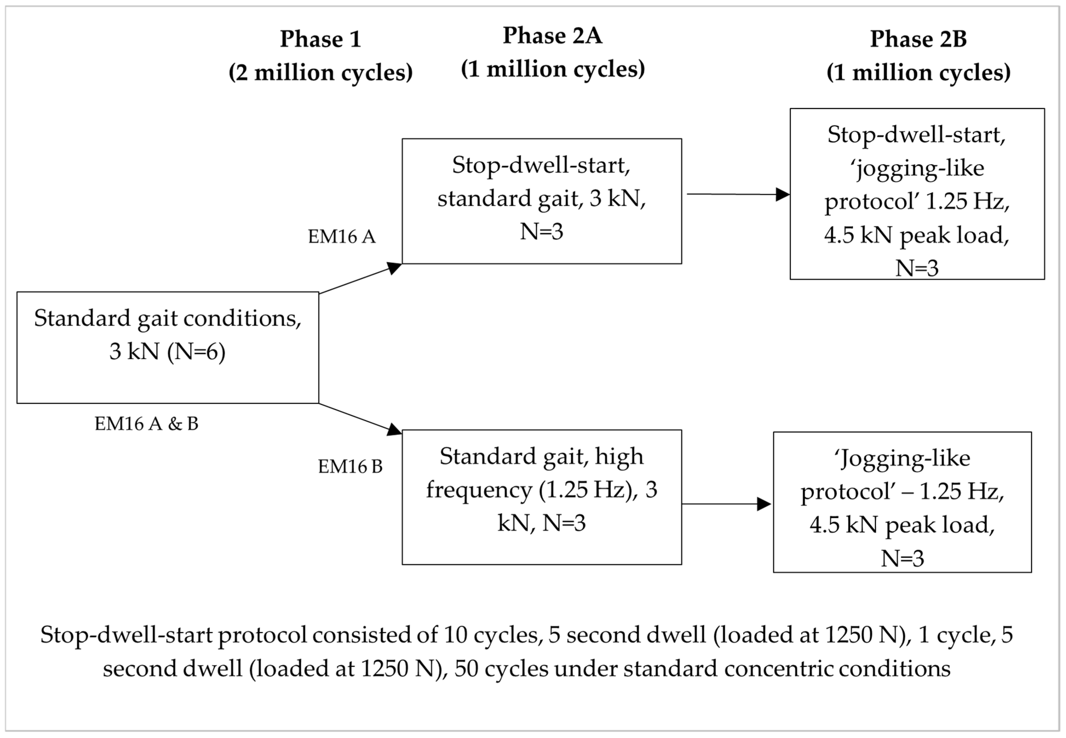
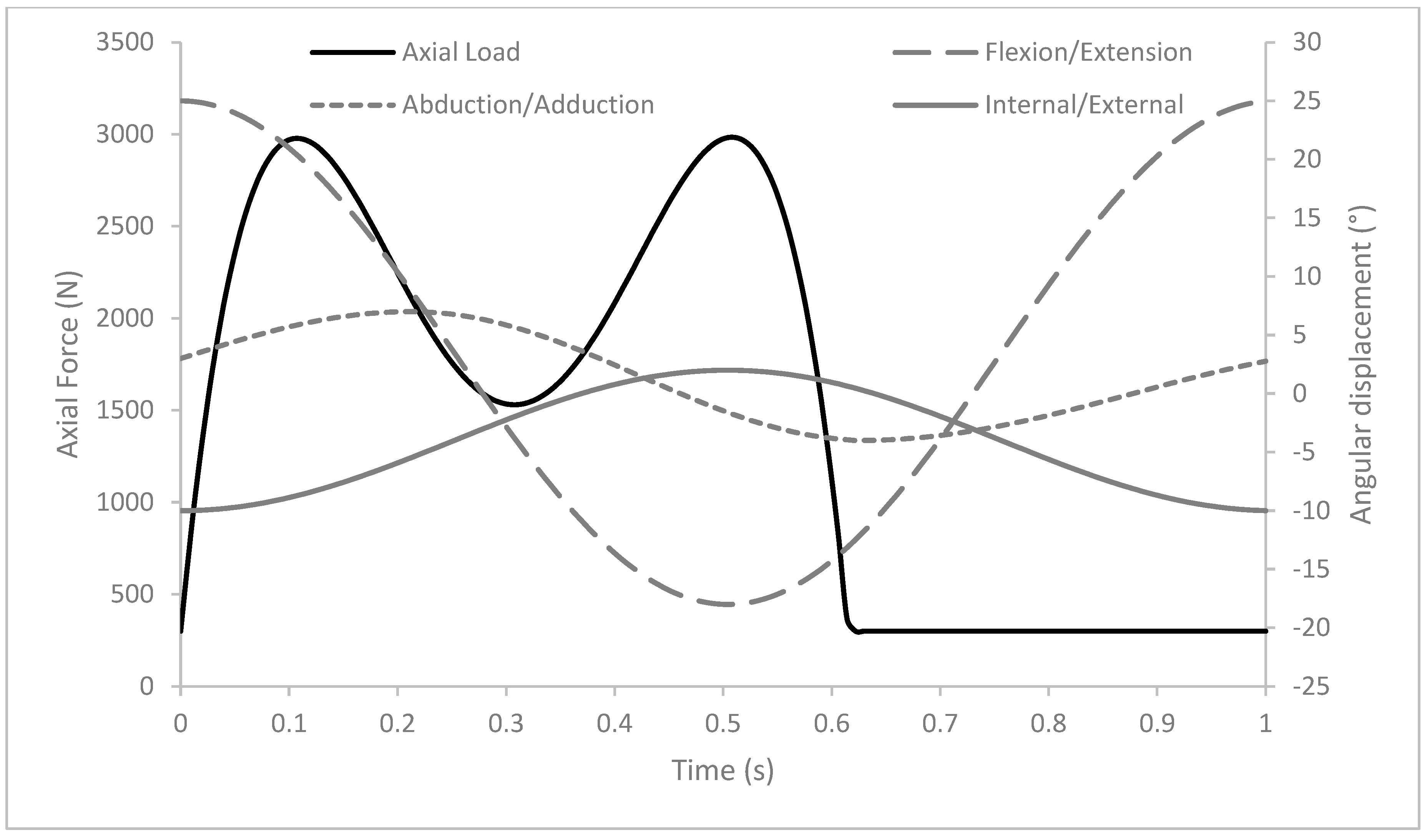
The experimental design is shown in Figure 3. Initially, all 6 ceramic-on-ceramic hip resurfacing implants were studied for 2 million cycles (MC) under ISO 14242-1 kinematic conditions [29] (Figure 4) to determine a baseline wear rate. For subsequent phases of the study, the 2 simulators were run under different conditions with 3 ceramic-on-ceramic hip resurfacing implants in each group. In one simulator, the aim was to build the complexity of the simulation towards a ‘jogging-like’ protocol; this was carried out in two stages. The first 1 MC wear simulation was carried out under higher frequency (1.25 Hz) followed by 1 MC simulation under higher frequency (1.25 Hz) and higher peak load (4.5 kN). Throughout the development of the ‘jogging-like’ protocol, the magnitude and shape of the input motions (i.e., flexion/extension, abduction/adduction, and internal/external rotation) were kept consistent with the standard gait profile used in phase 1. The shape of the input axial force waveform was also consistent throughout the study but the peak load was varied between 3 kN and 4.5 kN. This approach allowed individual variables—in this case, the frequency and applied load—to be investigated systematically. In the second simulator, the influence of a stop–dwell–start protocol was investigated. The protocol used was adapted from Hadley et al. and consisted of 10 gait cycles followed by a 5 s dwell loaded at 1250 N, 1 gait cycle, 5 s loaded dwell, and then 50 gait cycles [28]. A ramp up and ramp down cycle was included at the start and end of each dwell period. After 1 MC under the stop–dwell–start protocol using ISO 14242-1 kinematics when the simulator was running, an additional 1 MC was carried out using the previously developed ‘jogging-like’ protocol, i.e., with a higher peak load of 4.5 kN and at a higher frequency of 1.25 Hz.
The lubricant used was 25% bovine serum (final protein concentration 16 g/L) supplemented with 0.03% (v/v) sodium azide solution to retard bacterial growth. The lubricant was changed every 0.25 MC. Simulation was carried out at room temperature to minimise test artefacts associated with protein precipitation and deposition [30,31]. The lubricant composition and temperature are consistent with a previous wear simulation carried out in Leeds [14,16]. The wear of the heads and cups was assessed by removing the components from their fixtures prior to cleaning and assessment gravimetrically using an XP205 digital microbalance (Mettler Toledo, Leicester, UK). The balance had a readability of 0.01 mg and a repeatability of 0.015 mg [32]. To maximise the repeatability of the measurements, the balance room temperature and humidity were carefully controlled (20 ± 2 °C and 45 ± 5% respectively). For each kinematic condition, a minimum of 2 measurement points were taken. The loss in mass of the ceramic-on-ceramic hip resurfacing heads and cups was converted to a wear volume using a density of 4.37 mg/mm3 for BIOLOX delta ceramic [33]. No soak compensation was carried out, consistent with a previous simulation of ceramic-on-ceramic bearings, as the ceramics used do not take up moisture [34,35]; however, an environmental control was used during weighing to understand how variations in the temperature and humidity of the balance room influenced the gravimetric measurements. The change in surface topography of the heads and cups was assessed prior to the start of the study and at its conclusion using a contacting Form Talysurf (Taylor Hobson, Leicester, UK) with a 2 µm conical tipped stylus. Form removal, filtering, and cutoffs were applied as appropriate to the material and the ISO standard [36]. The surface roughness parameters of interest were the mean surface roughness (Ra), the maximum profile height (Rp), and the maximum valley depth (Rv). Pre-test and post-test data are presented. The location of the wear scar on the heads and cups was determined using a coordinate measurement machine (CMM) (Legex 322, Mitutoyo, Japan) with a 3 mm probe. A total of 72 traces were taken radially over the surface of the head and cup, and imported into RedLux OmniLux Studio, Romsey, UK. The wear scar was visualised as the deviation of the measurement from a nominal sphere.
The wear volume and wear rate of the heads and cups were calculated from gravimetric data. Data are presented as means ±95% confidence limits for the wear volume, wear rate, Ra, Rp, and Rv. Statistical analysis of the surface roughness (Ra, Rp, Rv) and wear rate of the implants was carried out to compare the pre- and post-test measurements using ANOVA in IBM SPSS Statistics Version 29 with a post hoc Tukey’s test. Significance was taken at p < 0.05.

3. Results

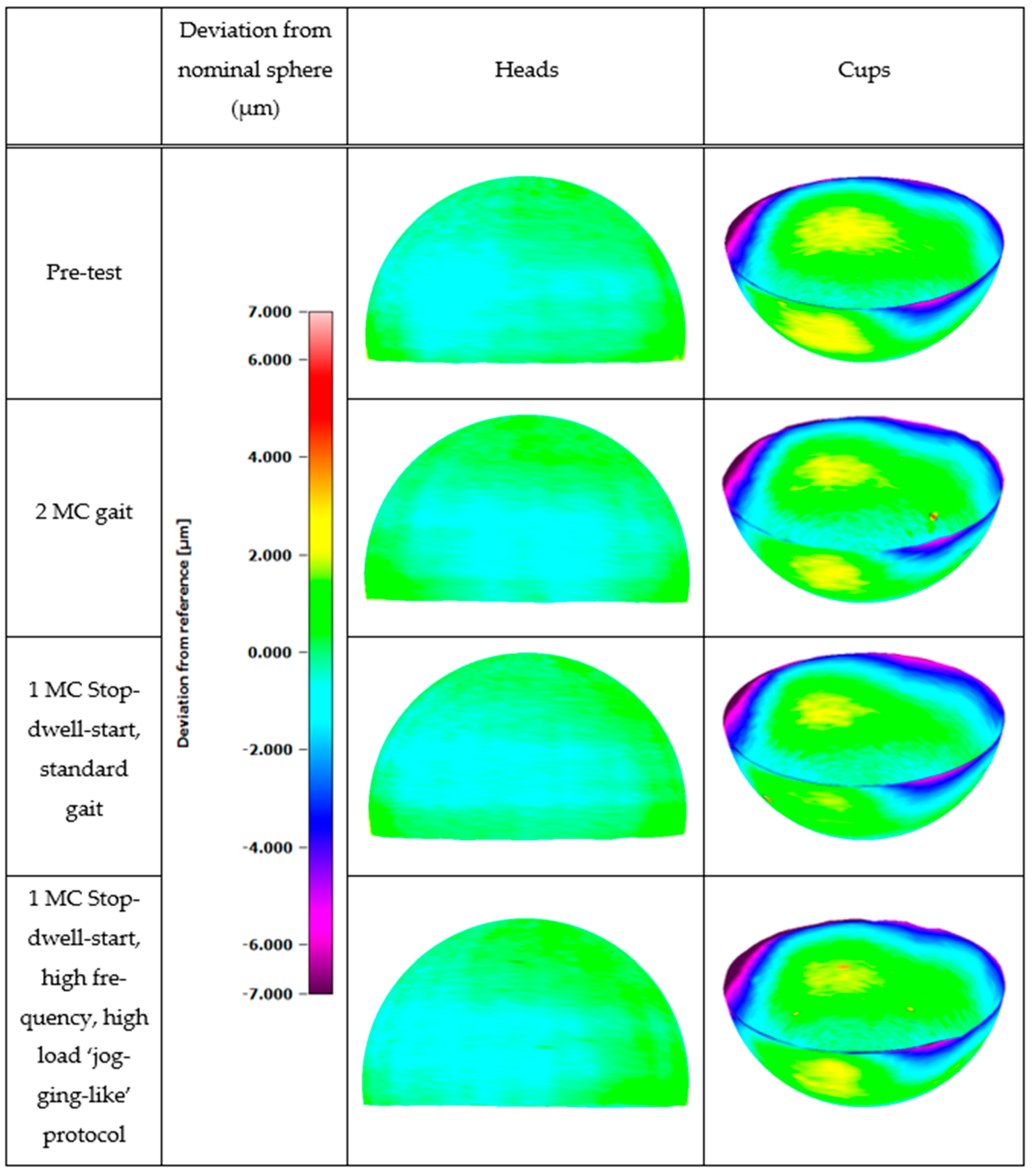
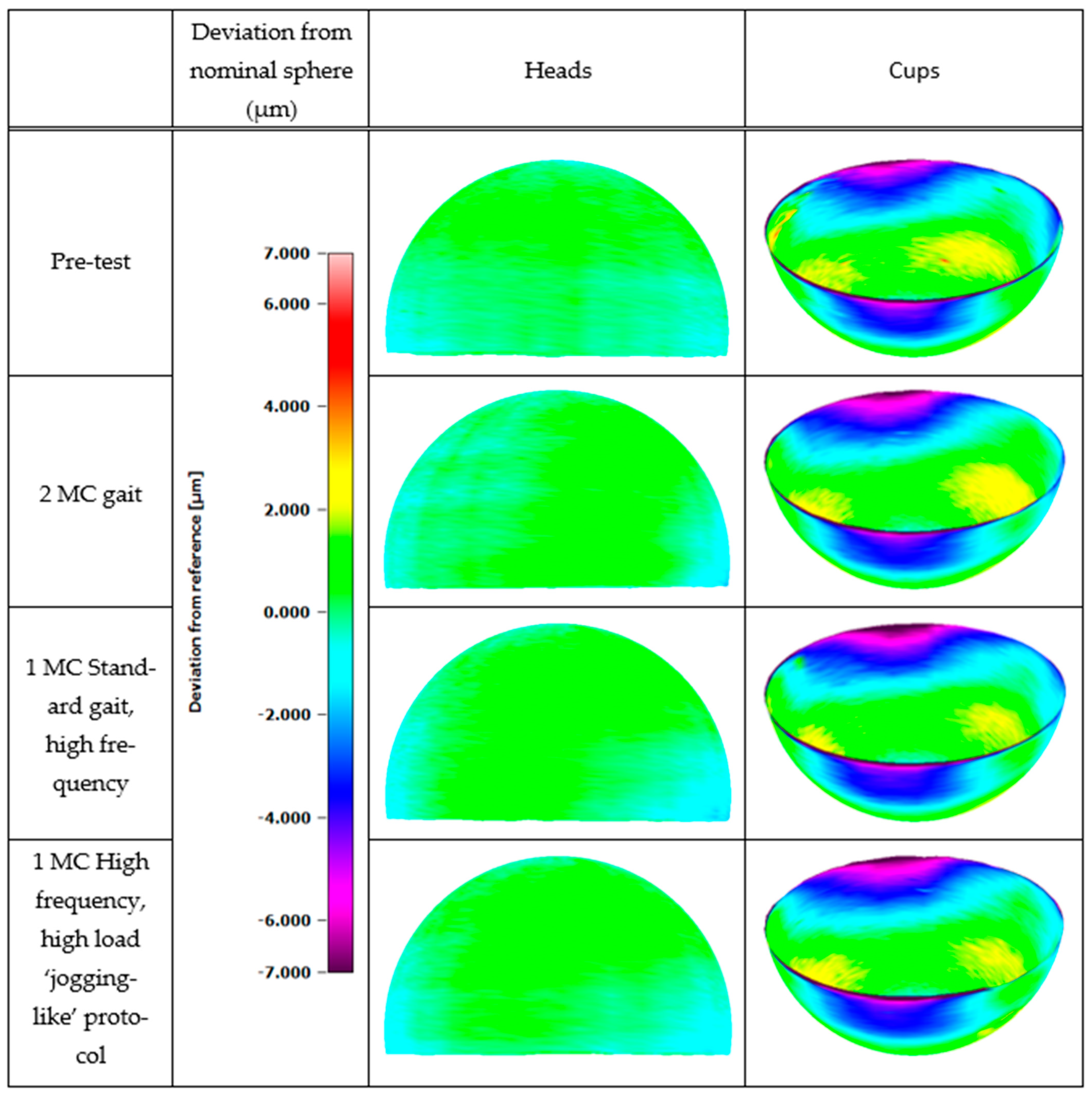
At the conclusion of each phase of the study, no wear scar or damage was visible on either the heads or cups. This observation was confirmed using a CMM; the images in Figure 5 and Figure 6 show the surface of components fitted to a nominal sphere and the deviation between the component and the sphere. For all the heads, the deviation was <±2 µm. This deviation was likely a combination of form errors both from the stylus and the ceramic component and means that a wear penetration depth < 2 µm was not detectable. In this study, the deviation in the pre-test measurements was similar to the post-test measurements, indicating that wear was not measurable geometrically. The deviation in the cups was higher than the heads, particularly around the rim region where the component had a radius of curvature which was manually removed from the measurement prior to form fitting. As with the heads, the pre-test and post-test measurements were similar.
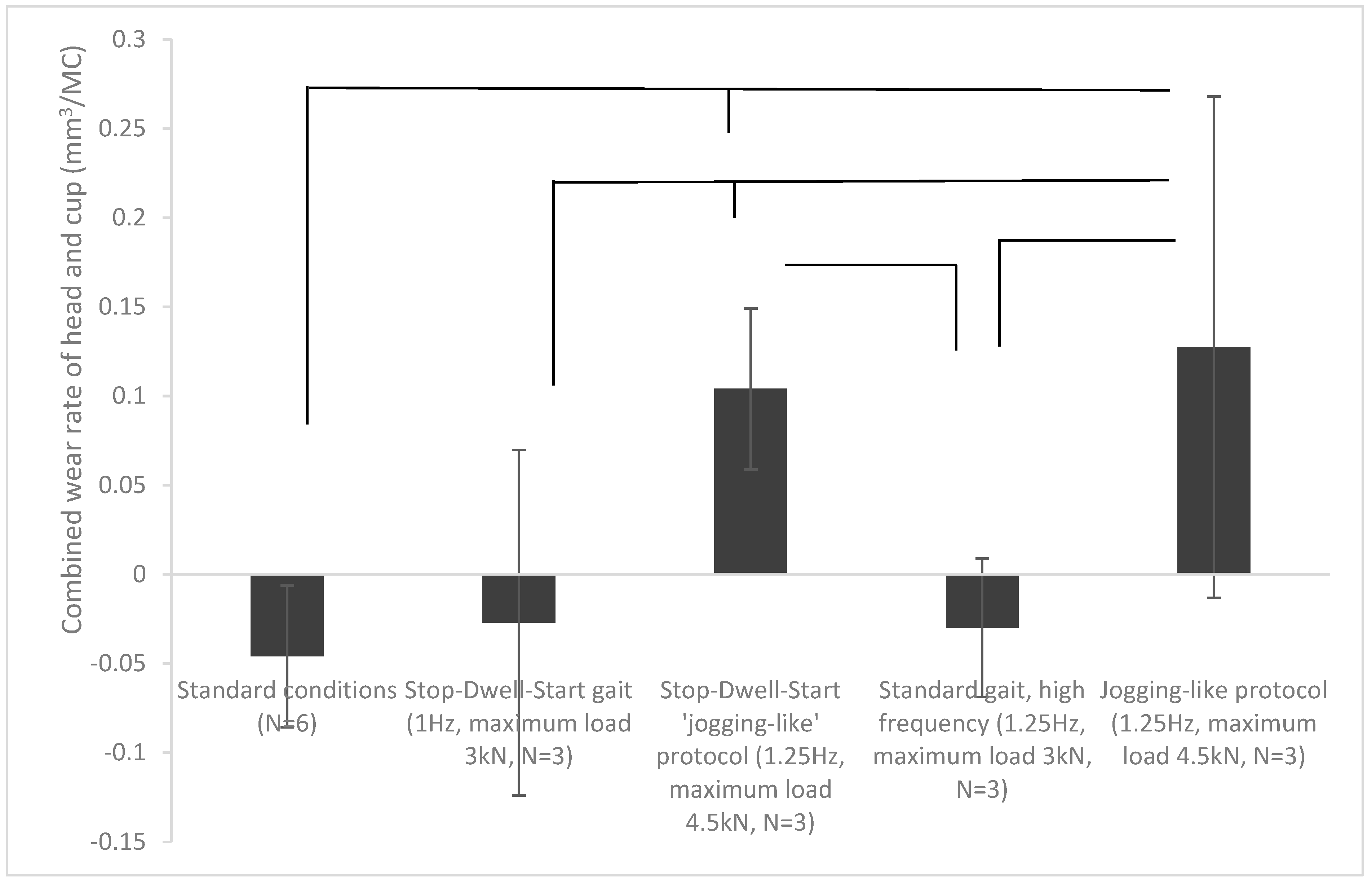
The mean wear rate of the heads and cups is shown in Figure 7. Under all conditions where the loading was 3 kN, mean wear rates were 0.01 mm3/MC or below. For conditions where loading was 4.5 kN, mean wear rates were in the range 0.09–0.13 mm3/MC (Figure 7). Statistical analysis showed no significant difference (p > 0.05) between experimental groups where the maximum load was 3 kN; when the maximum load was 4.5 kN, wear was significantly higher (p < 0.05) than for tests carried out under 3 kN loading. It is important to note that negative or near-zero values were likely as a result of measurement artefacts and random errors in the system that occur when trying to measure low wear volumes rather than a gain in material.
There was no visible scratching on the bearing surfaces, and for all the surface roughness parameters of interest (Ra, Rp, and Rv), no significant difference (p > 0.05) in the pre- and post-test measurements for either the heads or the cups was calculated (Table 1 and Table 2).
Intermittent squeaking was apparent from some, but not all, ceramic-on-ceramic hip resurfacing implants during the stop–dwell–start protocol when the simulator stopped. Squeaking was not heard during any of the protocols where the ceramic-on-ceramic hip resurfacing implants were run continuously.

4. Discussion

The aim of the study was to investigate the wear of a ceramic-on-ceramic hip resurfacing under activities of daily function, namely a walking gait, jogging-like profile, and stop–dwell–start protocol.
Under all the activities of daily function investigated, the combined wear of the head and cup of the ceramic-on-ceramic hip resurfacing bearing couple was very low (mean <0.15 mm3/MC), at the limit of the measurement sensitivity with no visual wear scar on the surface of the components or change in surface topography. Under walking gait conditions, the measured wear rates were a similar magnitude to the steady-state wear rate (<0.01 mm3/MC) of the same device tested under ISO 14242-1 conditions [10]. Previous wear simulation of this ceramic-on-ceramic hip resurfacing has shown initial higher wear rates in the first million cycles of wear simulation (0.23 mm3/MC) due to run-in wear; in the current study, the wear rate of the heads and cups was low at each measurement point.
Previous investigations of this ceramic-on-ceramic hip resurfacing implant have been carried out under edge-loading conditions (ISO 14242-4) [38], showing a higher wear rate than when studied under gait conditions, with a visible stripe on the head typical of edge-loading conditions [14,22]. One investigation of this ceramic-on-ceramic hip resurfacing implant has also investigated wear under a protocol of jogging combined with a stop–dwell–start protocol [39]. A low rate of wear of the heads and cups was measured with no wear scar evident or measurable change in surface topography; however, information relating to the study protocol used for the wear simulation is limited. In this study, the approach taken to develop and understand the implications of different loading and kinematic parameters such as the stop–dwell–start and a ‘jogging-like’ protocol was to build up profiles systematically. For the ‘jogging-like’ protocol, initially, the loading and kinematic profiles were kept consistent with the standard gait protocol with only the frequency of the simulation increased to understand the influence of increased frequency on wear before coupling the increased frequency with higher loading. Increasing frequency alone had no influence (p > 0.05) on the wear rate of the ceramic-on-ceramic hip resurfacing components compared to a standard walking gait. In the next phase of the study, an increased frequency was coupled with higher peak axial loads to deliver a ‘jogging-like’ protocol. Under the ‘jogging-like’ conditions, the combined wear rate of the ceramic-on-ceramic hip resurfacing heads and cups was significantly higher (p < 0.05) than when tested under standard conditions or higher frequency alone at 0.13 ± 0.14 mm3/MC. It is worth noting that this value is still lower than the wear rate of the same materials when tested under other adverse conditions such as edge loading (mean ~0.22 mm3/MC for studies of total hip replacements and resurfacings) [10,14]. Similarly, the stop–dwell–start protocol was initially carried out using a walking gait. When the peak load was 3 kN, there was no significant difference (p > 0.05) in the combined wear rate of the heads and cups under the stop–dwell–start protocol compared to continuous a running protocol; only when the peak load was increased to 4.5 kN was the combined wear rate of the head and cup significantly higher (p < 0.05).
Limited studies have investigated the influence of frequency on joint replacement wear. An experimental wear simulation study of a metal-on-polyethylene hip showed fast walking (1.75 Hz) to result in a much larger increase in wear rate compared to standard walking, jogging, and stumbling. However, the studies were of very short duration (0.25 MC) and the input profiles were not consistent across the different activities [40]. Similar findings have been shown in silico with a study of a metal-on-polyethylene hip replacement also demonstrating higher UHMWPE wear during fast walking compared to walking at 1 Hz, although the details relating to the input kinematics are minimal [41,42]. It is important to note that these studies were carried out on metal-on-polyethylene implants, the tribology of which differs from the ceramic-on-ceramic materials used in this study; as such, the findings may not directly translate.
The stop–dwell–start protocol used was adapted from previous work by Hadley et al., who showed a protocol of 10 gait cycles followed by a 5 s dwell to increase the wear rate of a Biolox Delta ceramic-on-ceramic bearing couple 15-fold compared to a walking gait; however, the mean wear rates remained very low (0.015 mm3/MC) and at the limit of the measurement sensitivity. These findings reflect those from the current study and reiterate the conclusion that BIOLOX delta ceramic-on-ceramic bearing materials do not perform unfavourably under adverse conditions such as the stop–dwell–start protocol. For other commonly used hip bearing materials such as metal-on-polyethylene and metal-on-metal, the increase in wear under stop–dwell–start conditions was much higher, up to 25 times that of standard walking [28].
Measuring low volumes of wear and identifying the penetration depth of shallow wear scars is difficult and often at the limit of the sensitivity and resolution of gravimetric and geometric measuring devices [25,28]. There are a number of contributory factors which make gravimetric analysis of low wear volumes difficult, including the need to remove all protein precipitate from the components whilst also avoiding damaging or scratching the implants; the sensitivity and accuracy of the balance, often limited to 0.01 mg for heavier, ceramic implants; and the environmental conditions. De Fine et al. suggested a limit for detection of wear gravimetrically at 0.1–0.2 mg for ceramic-on-ceramic bearing couples and Al-Hajjar et al. gave a limit of 1 µm penetration depth for geometric assessment of ceramics using a CMM [14]. All lower-load conditions in this study were at the limit of sensitivity for measuring wear, with only the adoption of high loading profiles (maximum load 4.5 kN) generating wear rates which could be reliably measured using the gravimetric technique. At the conclusion of the study, the depth of the wear scar was <1 µm, meaning that geometric assessment of the ceramic-on-ceramic hip resurfacing implants was also an unreliable method for determining wear in this short duration investigation.
During the stop–dwell–start protocol, intermittent squeaking occurred. Squeaking of ceramic-on-ceramic bearings has been reported in vivo, with most studies reporting infrequent squeaking to occur in fewer than 20% of ceramic-on-ceramic hip replacements, with persistent squeaking at a much lower rate [43,44,45]. In a study of 149 patients with ceramic-on-ceramic hip replacements, squeaking was reported in 14 (10.7%) patients and was associated with a range of activities including bending, walking, and stair climbing. Squeaking was not associated with pain and in many cases was benign, with only 1 patient in the cohort who considered the squeak to be sufficiently problematic to consider revision [43].
There are a number of factors thought to contribute to squeaking of ceramic-on-ceramic bearings in vivo including a mismatch in the materials [46] used in the ceramic-on-ceramic bearing couple, metal transfer on the articulating surfaces, impingement, third body wear, and “stripe-wear” caused by edge loading [47,48]. However, all these factors are associated with longer-term use of the joint than considered in this study and in some cases also associated with surgical mal-positioning. It is likely in the case of this simulator study that the squeak was due to the stopping of the simulator disrupting the lubrication between the articulating surfaces, leading to resonance or a stick slip mechanism [49,50]. In the case of this investigation, intermittent squeaking occurred under the stop–dwell–start conditions only as the simulator came to a stop and there was no acceleration in wear associated with the hip resurfacing implants that squeaked. Ceramic-on-ceramic bearings operate in a mixed lubrication regime; the occurrence of squeaking is thought to be due to disruption in the lubrication of the joint causing higher friction at the interface of the joint and subsequent vibration [51,52,53]. It is important to note that the motors used in the electromechanical simulator respond quickly to changes in the input profile, which means that the simulator stops very abruptly. This could exacerbate the vibration and subsequent squeak; in the body, changes in direction would occur more slowly with vibrations damped by the soft tissues in the body [52].
There are a number of limitations associated with this study, including the short duration of the investigations; however, the approach of building up the complexity of the simulation allowed the influence of individual variables such as frequency or applied load to be investigated. The small sample size (N = 3), which was restricted by the number of stations in the simulator, was another limitation. A sufficient number of samples was used to show trends; however, when interpreting results based on small sample sizes, care should be taken. Also, the test parts differed from the clinical components in that the internal geometry and surface topography of the components were modified to enable the head and cup to be removed from the cement mantle for gravimetric analysis. It is unlikely that the absence of features would have influenced the mechanical properties of the components due to the coating which was removed being very thin and the ceramic components being high-modulus and mounted onto a rigid cement fixture. The loss of some of the internal geometric features had the potential to cause the orientation of the components to change during the test; to ensure this did not occur, the relative position of the components on their fixtures was monitored during testing to ensure consistency. This approach was consistent with previous wear simulation of this device [10]. In addition, all the profiles used the same flexion/extension, internal/external rotation, and abduction/adduction inputs to isolate the influence of different variables investigated during development of the experimental methods; however, it is acknowledged that during jogging, these inputs will likely differ from those under a gait cycle and this is a limitation of the approach taken. This study assumed optimal implant positioning and the kinematics used are those of an average patient. Further, this simulation did not account for other factors known to influence the wear behaviour of hip prostheses, such as component mal-positioning, surgical variability, or patient-specific biomechanics [4,14,16,34,54].

5. Conclusions

This short-term, pre-clinical study showed low wear of BIOLOX delta ceramic-on-ceramic hip resurfacings when evaluated under a range of activities of daily living (walking and ‘jogging-like’ protocols, with and without stop–dwell–start protocols) and that this material combination has potential for the next generation of large-diameter hip bearings.

Author Contributions

Conceptualization, R.M.C., D.d.V., S.N.C., and L.M.J.; methodology, R.M.C., D.d.V., S.N.C., and L.M.J.; validation, R.M.C. and L.M.J.; formal analysis, R.M.C. and L.M.J.; investigation, R.M.C.; resources, L.M.J.; data curation, L.M.J.; writing—original draft preparation, R.M.C.; writing—review and editing, L.M.J.; visualisation, R.M.C. and L.M.J.; supervision, L.M.J.; project administration, L.M.J.; funding acquisition, L.M.J. All authors have read and agreed to the published version of the manuscript.

Funding

MatOrtho Ltd. provided implants. The research study was funded by the EPSRC through the ‘Innovation and Knowledge Centre Phase 2′ grant (reference EP/N00941X/1).

Data Availability Statement

The data associated with this paper and further supplementary information such as the occurrence of squeaking are openly available from the University of Leeds Data Repository at https://doi.org/10.5518/1831 [37].

Acknowledgments

Thanks go to Phil Wood for technical assistance.

Conflicts of Interest

Danielle de Villiers and Simon Collins are paid employees of MatOrtho Ltd. who provided implants and contributed to the study design but had no influence on the measurements or interpretation of the findings.

Abbreviations

The following abbreviations are used in this manuscript:
CMMCoordinate measurement machine
THRTotal Hip Replacement
MCMillion cycles
ADLActivities of Daily Living
SDSStop–Dwell–Start
PMMAPoly (methyl methacrylate)
ASTMAmerican Society for Testing and Materials
ISOInternational Organization for Standardization
RaMean surface roughness
RpMaximum profile height
RvMaximum valley depth

References

  1. Quesada, M.J.; Marker, D.R.; Mont, M.A. Metal-on-Metal Hip Resurfacing: Advantages and Disadvantages. J. Arthroplast. 2008, 23, 69–73. [Google Scholar] [CrossRef]
  2. Bini, F.; D’Alessandro, S.; Pica, A.; Marinozzi, F.; Cidonio, G. Harnessing biofabrication strategies to re-surface osteochondral defects: Repair, enhance, and regenerate. Biomimetics 2023, 8, 260. [Google Scholar] [CrossRef]
  3. National Joint Registry Annual Report 2025. 2025. Available online: https://reports.njrcentre.org.uk/Portals/0/PDFdownloads/NJR%2022nd%20Annual%20Report%202025.pdf (accessed on 14 April 2026).
  4. Fisher, J.; Al Hajjar, M.; Williams, S.; Tipper, J.; Ingham, E.; Jennings, L. (v) Simulation and measurement of wear in metal-on-metal bearings in vitro-understanding the reasons for increased wear. Orthop. Trauma 2012, 26, 253–258. [Google Scholar] [CrossRef][Green Version]
  5. Mabilleau, G.; Kwon, Y.-M.; Pandit, H.; Murray, D.W.; Sabokbar, A. Metal-on-metal hip resurfacing arthroplasty: A review of periprosthetic biological reactions. Acta Orthop. 2008, 79, 734–747. [Google Scholar] [CrossRef]
  6. Pandit, H.; Glyn-Jones, S.; McLardy-Smith, P.; Gundle, R.; Whitwell, D.; Gibbons, C.; Ostlere, S.; Athanasou, N.; Gill, H.; Murray, D. Pseudotumours associated with metal-on-metal hip resurfacings. J. Bone Jt. Surg. Br. 2008, 90, 847–851. [Google Scholar] [CrossRef] [PubMed]
  7. Mont, M.A.; Schmalzried, T.P. Modern Metal-on-Metal Hip Resurfacing: Important Observations from the First Ten Years. J. Bone Jt. Surg. 2008, 90, 3–11. [Google Scholar] [CrossRef] [PubMed]
  8. Tan, T.L.; Ebramzadeh, E.; Campbell, P.A.; Al-Hamad, M.; Amstutz, H.C. Long-Term Outcome of a Metal-on-Polyethylene Cementless Hip Resurfacing. J. Arthroplast. 2014, 29, 802–807. [Google Scholar] [CrossRef] [PubMed]
  9. Treacy, R.B.C.; Holland, J.P.; Daniel, J.; Ziaee, H.; McMinn, D.J.W. Preliminary report of clinical experience with metal-on-highly-crosslinked-polyethylene hip resurfacing. Bone Jt. Res. 2019, 8, 443–450. [Google Scholar] [CrossRef]
  10. de Villiers, D.; Collins, S. Wear of large diameter ceramic-on-ceramic hip bearings under standard and microseparation conditions. Biotribology 2020, 21, 100117. [Google Scholar] [CrossRef]
  11. de Villiers, D.; Richards, L.; Tuke, M.; Collins, S. Ceramic resurfacing: The future and challenges. Ann. Jt. 2020, 5, 12. [Google Scholar] [CrossRef]
  12. Lin, D.; Xu, J.; Weinrauch, P.; Young, D.A.; De Smet, K.; Manktelow, A.; Beaulé, P.E.; Walter, W.L. Two-Year Results of Ceramic-on-Ceramic Hip Resurfacing in an International Multicenter Cohort. J. Arthroplast. 2024, 39, 2800–2806. [Google Scholar] [CrossRef]
  13. Sun, C.W.Y.; Lau, L.C.M.; Cheung, J.P.Y.; Choi, S.W. Cancer-Causing Effects of Orthopaedic Metal Implants in Total Hip Arthroplasty. Cancers 2024, 16, 1339. [Google Scholar] [CrossRef] [PubMed]
  14. Al-Hajjar, M.; Fisher, J.; Tipper, J.L.; Williams, S.; Jennings, L.M. Wear of 36-mm BIOLOX® delta ceramic-on-ceramic bearing in total hip replacements under edge loading conditions. Proc. Inst. Mech. Eng. Part H 2013, 227, 535–542. [Google Scholar] [CrossRef]
  15. Gibon, E.; Córdova, L.A.; Lu, L.; Lin, T.H.; Yao, Z.; Hamadouche, M.; Goodman, S.B. The biological response to orthopedic implants for joint replacement. II: Polyethylene, ceramics, PMMA, and the foreign body reaction. J. Biomed. Mater. Res. B 2017, 105, 1685–1691. [Google Scholar] [CrossRef] [PubMed]
  16. O’Dwyer Lancaster-Jones, O.; Williams, S.; Jennings, L.; Thompson, J.; Isaac, G.; Fisher, J.; Al-Hajjar, M. An in vitro simulation model to assess the severity of edge loading and wear, due to variations in component positioning in hip joint replacements. J. Biomed. Mater. Res. B 2018, 106, 1897–1906. [Google Scholar] [CrossRef] [PubMed]
  17. Park, J.-W.; Ko, Y.-S.; Lee, Y.-K.; Ha, Y.-C.; Koo, K.-H. Ten to 13-Year Results of Delta Ceramic-on-Ceramic Total Hip Arthroplasty in Patients Less Than 30 Years Old. J. Bone Jt. Surg. 2023, 105, 789–796. [Google Scholar] [CrossRef]
  18. Kurtz, S.M.; Kocagöz, S.; Arnholt, C.; Huet, R.; Ueno, M.; Walter, W.L. Advances in zirconia toughened alumina biomaterials for total joint replacement. J. Mech. Behav. Biomed. Mater. 2014, 31, 107–116. [Google Scholar] [CrossRef]
  19. Park, J.-W.; Kim, H.-S.; Kim, K.-C.; Lee, Y.-K.; Ha, Y.-C.; Koo, K.-H. A 10- to 12-year follow-up study of delta ceramic-on-ceramic total hip arthroplasty. Arch. Orthop. Trauma Surg. 2023, 143, 5385–5394. [Google Scholar] [CrossRef]
  20. Vendittoli, P.-A.; Shahin, M.; Rivière, C.; Barry, J.; Lavoie, P.; Duval, N. Ceramic-on-ceramic total hip arthroplasty is superior to metal-on-conventional polyethylene at 20-year follow-up: A randomised clinical trial. Orthop. Traumatol. Surg. Res. 2021, 107, 102744. [Google Scholar] [CrossRef]
  21. Ko, Y.-S.; Kang, S.Y.; Kim, H.S.; Park, J.-W.; Lee, Y.-K.; Yoo, J.J. Incidence of Ceramic Component Fractures in Total Hip Arthroplasty Using Contemporary Ceramic-On-Ceramic Bearings: A Retrospective Study Spanning Two Decades From Two Tertiary Referral Hospitals. J. Arthroplast. 2025, 40, 1055–1061.e1053. [Google Scholar] [CrossRef]
  22. Nevelos, J.; Ingham, E.; Doyle, C.; Streicher, R.; Nevelos, A.; Walter, W.; Fisher, J. Microseparation of the centers of alumina-alumina artificial hip joints during simulator testing produces clinically relevant wear rates and patterns. J. Arthroplast. 2000, 15, 793–795. [Google Scholar] [CrossRef]
  23. Nevelos, J.E.; Ingham, E.; Doyle, C.; Fisher, J.; Nevelos, A.B. Analysis of retrieved alumina ceramic components from Mittelmeier total hip prostheses. Biomaterials 1999, 20, 1833–1840. [Google Scholar] [CrossRef]
  24. Maslivec, A.; Allott, N.; Guest, B.; Halewood, C.; Cobb, J.P. Functional assessment of ceramic-on-ceramic hip resurfacing arthroplasty. Bone Jt. J. 2026, 108, 447–454. [Google Scholar] [CrossRef]
  25. Jennings, L.M.; Al-Hajjar, M.; Brockett, C.L.; Williams, S.; Tipper, J.L.; Ingham, E.; Fisher, J. (iv) Enhancing the safety and reliability of joint replacement implants. Orthop. Trauma 2012, 26, 246–252. [Google Scholar] [CrossRef][Green Version]
  26. ASTM F3018-17; Standard Guide for Assessment of Hard-on-Hard Articulation Total Hip Replacement and Hip Resurfacing Arthroplasty Devices. ASTM: West Conchohocken, PA, USA, 2017. Available online: https://store.astm.org/f3018-17.html (accessed on 14 April 2026).
  27. ASTM F3047M-23; Standard Guide for High Demand Hip Simulator Wear Testing of Hard-on-Hard Articulations. ASTM: West Conchohocken, PA, USA, 2017. Available online: https://store.astm.org/f3047m-23.html (accessed on 14 April 2026).
  28. Hadley, M.; Hardaker, C.; Isaac, G.; Fisher, J. Wear of different materials for total hip replacement under adverse stop-dwell-start in vitro wear simulation conditions. Proc. Inst. Mech. Eng. Part H 2018, 232, 1261–1270. [Google Scholar] [CrossRef]
  29. ISO 14242-1:2014; Implants for surgery—Wear of Total Hip-Joint Prostheses. Part 1: Loading and Displacement Parameters for Wear-Testing Machines and Corresponding Environmental Conditions for Test. ISO: Geneva, Switzerland, 2014. Available online: https://www.iso.org/standard/63073.html (accessed on 14 April 2026).
  30. Cowie, R.M.; Briscoe, A.; Fisher, J.; Jennings, L.M. Wear and Friction of UHMWPE-on-PEEK OPTIMA™. J. Mech. Behav. Biomed. Mater. 2019, 89, 65–71. [Google Scholar] [CrossRef] [PubMed]
  31. Cowie, R.M.; Briscoe, A.; Jennings, L.M. The influence of lubricant temperature on the wear of total knee replacements. Biosurf. Biotribol. 2023, 9, 71–77. [Google Scholar] [CrossRef]
  32. XP205 Analytical Balance. Available online: https://www.mt.com/in/en/home/phased_out_products/Laboratory_Weighing_Solutions/Analytical/xp205.html (accessed on 14 April 2026).
  33. BIOLOX Delta Material Rationale. 2013. Available online: https://astramed.com.br/portal/images/catalogos/proteses/protese_quadril/cabecas_femorais/DPY_Biolox_Delta_Material_Rationale_0612-28-500r2.pdf (accessed on 12 February 2026).
  34. Ali, M.; Al-Hajjar, M.; Fisher, J.; Jennings, L.M. The Influence of Kinematic Conditions and Variations in Component Positioning on the Severity of Edge Loading and Wear of Ceramic-on-Ceramic Hip Bearings. Ceramics 2019, 2, 488–501. [Google Scholar]
  35. De Fine, M.; Terrando, S.; Hintner, M.; Porporati, A.A.; Pignatti, G. Pushing Ceramic-on-Ceramic in the most extreme wear conditions: A hip simulator study. Orthop. Traumatol. Surg. Res. 2021, 107, 102643. [Google Scholar] [CrossRef] [PubMed]
  36. ISO 21920-3:2021; Geometrical Product Specifications (GPS)—Surface Texture: Profile Part 3: Specification Operators. ISO: Geneva, Switzerland, 2021. Available online: https://www.iso.org/standard/72228.html (accessed on 14 April 2026).
  37. Cowie, R.M.; Jennings, L. Dataset Associated with “Wear of a Ceramic-on-Ceramic Hip Resurfacing Under Activities of Daily Function”; University of Leeds: Leeds, UK, 2026. [Google Scholar]
  38. ISO 14242-4:2018; Implants for Surgery—Wear of Total Hip-Joint Prostheses. Part 4: Testing Hip Prostheses Under Variations in Component Positioning Which Results in Direct Edge Loading. ISO: Geneva, Switzerland, 2018. Available online: https://www.iso.org/standard/63835.html (accessed on 14 April 2026).
  39. Beadling, A.; Pryce, G.; De Villiers, D.; Collins, S.; Bryant, M. Adverse Preclinical Testing of Ceramic-on-Ceramic Hip Resurfacing. In Proceedings of the International Society for Technology in Arthroplasty Annual Congress, New York, NY, USA, 27–30 September 2023. [Google Scholar]
  40. Bowsher, J.G.; Shelton, J.C. A hip simulator study of the influence of patient activity level on the wear of crosslinked polyethylene under smooth and roughened femoral conditions. Wear 2001, 250, 167–179. [Google Scholar] [CrossRef]
  41. Mattei, L.; Di Pietro, A.; Di Puccio, F. How Patients’ Lifestyle Affects the Wear of Hip Implants: An In-Silico Study. J. Orthop. Res. 2025, 43, 1472–1484. [Google Scholar] [CrossRef]
  42. Mattei, L.; Tomasi, M.; Artoni, A.; Ciulli, E.; Di Puccio, F. Combination of musculoskeletal and wear models to investigate the effect of daily living activities on wear of hip prostheses. Proc. Inst. Mech. Eng. Part J J. Eng. Tribol. 2021, 235, 2675–2687. [Google Scholar] [CrossRef]
  43. Jarrett, C.A.; Ranawat, A.S.; Bruzzone, M.; Blum, Y.C.; Rodriguez, J.A.; Ranawat, C.S. The Squeaking Hip: A Phenomenon of Ceramic-on-Ceramic Total Hip Arthroplasty. J. Bone Jt. Surg. 2009, 91, 1344–1349. [Google Scholar] [CrossRef]
  44. Keurentjes, J.C.; Kuipers, R.M.; Wever, D.J.; Schreurs, B.W. High Incidence of Squeaking in THAs with Alumina Ceramic-on-ceramic Bearings. Clin. Orthop. Relat. Res. 2008, 466, 1438–1443. [Google Scholar] [CrossRef] [PubMed]
  45. McDonnell, S.M.; Boyce, G.; Baré, J.; Young, D.; Shimmin, A.J. The incidence of noise generation arising from the large-diameter Delta Motion ceramic total hip bearing. Bone Jt. J. 2013, 95, 160–165. [Google Scholar] [CrossRef]
  46. Morlock, M.; Nassutt, R.; Janssen, R.; Willmann, G.; Honl, M. Mismatched wear couple zirconium oxide and aluminum oxide in total hip arthroplasty. J. Arthroplast. 2001, 16, 1071–1074. [Google Scholar] [CrossRef]
  47. Schroeder, S.; Gaedeke, L.; Hariri, M.; Bormann, T.; Weiss, M.; Kretzer, J.P.; Uhler, M. Ceramic–Ceramic Hip Implants: Investigation of Various Factors Associated with Squeaking. Lubricants 2024, 12, 438. [Google Scholar] [CrossRef]
  48. Taylor, S.; Manley, M.T.; Sutton, K. The role of stripe wear in causing acoustic emissions from alumina ceramic-on-ceramic bearings. J. Arthroplast. 2007, 22, 47–51. [Google Scholar] [CrossRef]
  49. O’Dwyer Lancaster-Jones, O.; Reddiough, R. The occurrence of squeaking under wear testing standards for ceramic on ceramic total hip replacements. J. Mech. Behav. Biomed. Mater. 2023, 138, 105616. [Google Scholar] [CrossRef] [PubMed]
  50. Rieker, C.; Köttig, P.; Schön, R.; Windler, M.; Wyss, U. Clinical wear performance of metal-on-metal hip arthroplasties. In Alternative Bearing Surfaces in Total Joint Replacement; ASTM International: West Conshohocken, PA, USA, 1998. [Google Scholar]
  51. Currier, J.H.; Anderson, D.E.; Van Citters, D.W. A proposed mechanism for squeaking of ceramic-on-ceramic hips. Wear 2010, 269, 782–789. [Google Scholar] [CrossRef]
  52. Sariali, E.; Stewart, T.; Jin, Z.; Fisher, J. In vitro investigation of friction under edge-loading conditions for ceramic-on-ceramic total hip prosthesis. J. Orthop. Res. 2010, 28, 979–985. [Google Scholar] [CrossRef] [PubMed]
  53. Walter, W.L.; Waters, T.S.; Gillies, M.; Donohoo, S.; Kurtz, S.M.; Ranawat, A.S.; Hozack, W.J.; Tuke, M.A. Squeaking Hips. J. Bone Jt. Surg. 2008, 90, 102–111. [Google Scholar] [CrossRef] [PubMed]
  54. Clegg, B.A.; Perry, S.; De Pieri, E.; Redmond, A.C.; Ferguson, S.J.; Lunn, D.E.; Hall, R.M.; Bryant, M.G.; Emami, N.; Beadling, A.R. Effects of Physiological Loading from Patient-Derived Activities of Daily Living on the Wear of Metal-on-Polymer Total Hip Replacements. Bioengineering 2025, 12, 663. [Google Scholar] [PubMed]
Figure 1. A ReCerf ceramic-on-ceramic resurfacing with modification to the fixation surface for the purpose of experimental simulation.
Lubricants 14 00219 g001
Figure 2. Photograph of a ReCerf hip set up in a ProSim simulator with the axial force and controlled axes of motion. The motions were delivered to the head whilst the force was applied through the cup.
Lubricants 14 00219 g002
Figure 3. Experimental design.
Lubricants 14 00219 g003
Figure 4. Load and angular displacement input kinematic conditions as per ISO 14242-1 for standard gait cycle. For the ‘jogging-like’ protocol, either the frequency of the gait cycle was increased to 1.25 Hz and/or the peak load was increased to 4.5 kN.
Lubricants 14 00219 g004
Figure 5. Images of the geometry of the heads and cups pre-test, after 2 MC gait simulation, 1 MC stop–dwell–start under a gait cycle, and 1 MC stop–dwell–start under a high-frequency, high-load “jogging-like” profile. CMM measurements were fitted to a nominal sphere in Redlux and the difference between the nominal sphere and the surface is shown in the shaded plots. Images are representative of those investigated in all 3 EM16A stations.
Lubricants 14 00219 g005
Figure 6. Images of the geometry of the heads and cups pre-test, after 2 MC gait simulation, 1 MC standard gait at high frequency, and 1 MC high-frequency, high-load “jogging-like” profile. CMM measurements were fitted to a nominal sphere in Redlux and the difference between the nominal sphere and the surface is shown in the shaded plots. Images are representative of those investigated in all 3 EM16B stations.
Lubricants 14 00219 g006
Figure 7. Combined wear rate (mm3/MC) ± 95% confidence limits of the heads and cups under the different study conditions. The lines denote a significant difference (p < 0.05) between experimental groups. Note: under stop–dwell–start conditions, the wear rate calculation included both active, ramp up, ramp down, and stopped cycles. For further statistical analysis see data repository [37].
Lubricants 14 00219 g007
Table 1. Mean surface roughness of cups (±95% confidence limits) pre-test (N = 6) and following either 4 MC under a standard gait followed by stop–dwell–start protocols (N = 3) or 4 MC under gait followed by high-frequency continuous running protocols (N = 3).
ParametersPre-TestPost-Test
EM16A—Stop–Dwell–Start ProtocolsEM16B—Continuous Running Protocols
Ra (µm)0.006 ± 0.0010.005 ± 0.0020.005 ± 0.002
Rp (µm)0.017 ± 0.0030.013 ± 0.0050.013 ± 0.006
Rv (µm)0.023 ± 0.0040.018 ± 0.0060.017 ± 0.008
Table 2. Mean surface roughness of heads (±95% confidence limits) pre-test (N = 6) and following either 4 MC under a standard gait followed by stop–dwell–start protocols (N = 3) or 4 MC under gait followed by high-frequency continuous running protocols (N = 3).
ParametersPre-TestPost-Test
EM16A—Stop–Dwell–Start ProtocolsEM16B—Continuous Running Protocols
Ra (µm)0.004 ± 0.0010.005 ± 0.0000.006 ± 0.002
Rp (µm)0.009 ± 0.0020.013 ± 0.0010.022 ± 0.027
Rv (µm)0.014 ± 0.0030.019 ± 0.0020.022 ± 0.006
Disclaimer/Publisher’s Note: The statements, opinions and data contained in all publications are solely those of the individual author(s) and contributor(s) and not of MDPI and/or the editor(s). MDPI and/or the editor(s) disclaim responsibility for any injury to people or property resulting from any ideas, methods, instructions or products referred to in the content.