1. Introduction
Lubricant film formation in concentrated contacts is fundamental to the reliability, efficiency, and durability of mechanical systems. In gears, rolling element bearings, piston–cylinder assemblies, and related machine elements, the lubricant film must separate metallic surfaces under high pressure and rolling or sliding motion; when the film becomes insufficient, lubrication may shift toward mixed or boundary regimes, leading to increased friction, wear, surface fatigue, and eventual failure [
1,
2,
3,
4]. The physical basis of film formation in such contacts is provided by elastohydrodynamic lubrication (EHL) theory, which couples hydrodynamic entrainment, pressure-dependent viscosity, and elastic deformation of the contacting bodies [
5,
6,
7,
8]. Optical interferometry established the classical experimental foundation of EHL film thickness research and revealed the characteristic inlet, Hertzian, and outlet regions of lubricated contacts [
4,
9,
10,
11]. However, optical methods require transparent specimens and carefully controlled geometries, which limits their direct use in practical, opaque, multi-contact machine elements.
This limitation motivated the development of indirect methods for in situ film thickness evaluation in practical machine elements. These methods do not provide the same type of information. Optical interferometry remains the most direct benchmark because it can resolve the spatial structure of EHL films and distinguish the inlet, Hertzian, and outlet regions, but it requires optical access, transparent specimens, and simplified laboratory geometries [
4,
9,
10,
11,
12]. Discharge- and resistance-based approaches are highly sensitive to film breakdown, metallic contact, and lubrication-regime transitions, but their electrical response is strongly affected by temperature, contamination, surface roughness, and local asperity contacts; they are therefore more suitable for detecting lubrication-state changes than for reconstructing an absolute EHL film thickness [
3,
13,
14,
15,
16]. Ultrasonic, fluorescence, optical-extinction, and related methods have provided valuable complementary routes for opaque or application-specific systems, but each requires its own assumptions regarding acoustic reflection, optical absorption, tracer response, or sensor calibration [
17,
18,
19].
Capacitance-based methods occupy a distinctive position among these approaches. Their main practical advantage is that they can be implemented in assembled or partially closed machine elements, including rolling bearings, piston assemblies, journal bearings, and other components where direct optical access is unavailable [
20,
21,
22,
23]. Their main limitation, however, is interpretive rather than purely instrumental: the measured capacitance is not a direct local film thickness but a global electrical response shaped by film geometry, dielectric properties, leakage, background capacitance, and electrical topology. Compared with optical interferometry, capacitance methods sacrifice direct spatial visualization; compared with resistance-based methods, they can retain a stronger link to film separation but only when dielectric and parasitic effects are adequately constrained.
This distinction becomes particularly important in grease-lubricated and starved systems. In such cases, oil bleeding, thickener entrainment, starvation, replenishment, grease formulation, and operating history can all influence film formation and alter the electrically active medium [
24,
25,
26,
27,
28,
29,
30,
31]. Therefore, the central difficulty is not simply choosing a sensitive measurement technique but determining what physical quantity a measured electrical response can legitimately support.
Over the past decades, capacitance-based film thickness methods have progressed from simple dielectric-gap analogies toward more explicit treatments of non-uniform film geometry, parasitic capacitances, mixed oil–air regions, frequency-dependent dielectric response, and multi-contact electrical topology [
32,
33,
34,
35,
36,
37,
38,
39]. Yet this progression should not be read as a uniform transition toward uniquely resolved film thickness. In many studies, the measured quantity remains a global electrical response from which geometry, dielectric state, leakage, contact topology, and background contributions are only partially separable. Under thin-film, starved, or grease-lubricated conditions, the measured response may reflect an effective dielectric response shaped by confinement, boundary layers, oil–air mixtures, and leakage pathways rather than a directly known bulk material constant [
40,
41,
42]. In addition, bearing-scale and component-scale measurements are usually network-embedded observables jointly affected by local film geometry, dielectric state, contact topology, and parasitic/background contributions [
33,
42,
43,
44]. The present review addresses this methodological problem not as a simple capacitance-to-thickness conversion issue but as an inverse interpretation problem whose physical meaning depends on what is measured, what is assumed known, what is actually inferred, and what validation supports that inference.
Accordingly, this review examines capacitance-based film thickness determination through four coupled interpretive layers—film geometry, dielectric response, electrical topology, and parasitic/background effects. Its purpose is not merely to summarize prior studies but to clarify where physical meaning is retained, where it becomes model-conditioned, and where non-uniqueness remains unavoidable. In particular, the review distinguishes between bulk dielectric properties, operationally identified dielectric-response parameters, equivalent thickness indicators, contact-scale proxies, and branch-resolved component-scale quantities. This distinction is important because similarly named “film thickness” results in the literature do not always represent the same inferential object.
This review is not intended as a systematic review but as a representative and analytically structured synthesis of the lines of work most relevant to modern capacitance-based film thickness interpretation. It focuses on studies in which capacitance responses, or impedance responses with a dominant capacitive contribution over the frequency range of interest, are used to infer lubricant film thickness or closely related lubrication descriptors. Optical, ultrasonic, resistance-based, and other non-capacitive methods are discussed only where needed as historical context, physical benchmarks, or validation references, and electrical bearing diagnostics unrelated to film thickness inference are excluded. Although the scope is broad across lubricated machine elements, the deepest methodological discussion is necessarily bearing-centered, because rolling bearings provide the richest literature on multi-contact topology, starvation, grease lubrication, and component-scale inverse interpretation. Recent work further indicates that this field remains active, with growing emphasis on grease-bearing measurements, improved rolling-bearing capacitance modeling, electrical-impedance-based interpretation, and validation in more realistic machine-element configurations [
45,
46,
47,
48]. The review is organized around the principal sources of interpretive difficulty—non-uniform film geometry, state-dependent dielectric response, electrical topology, and parasitic/background effects—and the strategies used to constrain them. The central question is not simply whether a method produces a thickness-like output but what level of physical claim that output can support under its stated assumptions and validation basis.
2. Physical Basis of Capacitance-Based Film Thickness Interpretation
Capacitance-based film thickness determination in lubricated machine elements is difficult because the measured electrical response is not controlled by film thickness alone. The following section therefore unpacks the physical origins of this difficulty, focusing on how non-uniform film geometry, state-dependent dielectric response, frequency-dependent loss, and electrical topology enter the measured signal.
A simple physical example illustrates why these constraints matter. In an electrically monitored rolling bearing used in an electric motor or gearbox, the measured terminal response does not originate from a single ball–raceway contact. Instead, several loaded and unloaded contacts, lubricant-filled and partially starved regions, shaft and housing paths, sensor leads, and background capacitances all contribute to the measured signal. A decrease in measured capacitance may therefore indicate an increase in local film thickness, a reduction in the electrically active oil-filled area, a change in effective permittivity caused by oil–air mixture formation, or a change in the number of active electrical pathways. This is why the same electrical trend can support different physical interpretations unless contact geometry, dielectric response, and network topology are constrained together.
This section does not review inversion procedures in detail. Its purpose is to define the physical constraints that later reappear as methodological differences between simpler equivalent-gap interpretations and more strongly constrained reconstruction routes.
2.1. Quasi-Electrostatic Description of Lubricated Contacts
At frequencies typically used in capacitance-based measurements, from several kHz to a few MHz, lubricated contacts can usually be described within the quasi-electrostatic approximation of Maxwell’s equations [
49]. Under this approximation, magnetic induction effects are neglected and the electric field
is governed by the electric potential
[
49],
Gauss’s law then gives [
49]
where
,
is the vacuum permittivity,
is the relative permittivity, and
is the free charge density. In lubricated contacts,
is often negligible in the bulk liquid, but spatial variations in
may arise from oil–air mixtures, boundary layers, confinement, and neighboring conductive structures [
20,
50].
Within this approximation, lubricated contacts are often represented by lumped electrical elements, provided that the excitation frequency remains in a range where such a reduction is physically meaningful [
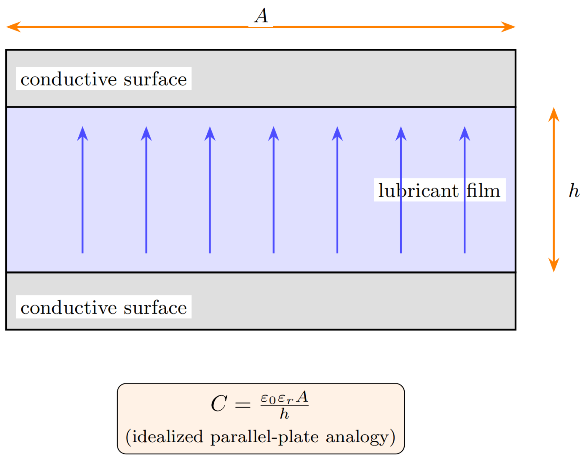
51]. For an idealized uniform dielectric layer of thickness
h between conductive surfaces of effective area
A, the capacitance is given by the classical parallel-plate relation, which also underpinned early capacitance-based interpretations of lubricated contacts [
20,
50],
Equation (
3) is the historical starting point for capacitance-based film thickness evaluation. Its value is interpretive rather than literal: in practical machine elements, the measured electrical quantity rarely corresponds to a single uniform dielectric gap. The relation is useful as a first-order guide but misleading if an equivalent electrical response is read as a unique local film thickness.
2.2. Non-Uniform EHL Film Geometry and the Local-to-Global Mismatch
In EHL contacts, film formation results from hydrodynamic pressure generation, elastic deformation, and pressure-dependent viscosity [
5,
7]. Under fully flooded conditions, the central film thickness for elliptical point contacts is commonly written in the Hamrock–Dowson form [
7,
8]
where
is the reduced radius in the rolling direction,
U is the speed parameter,
G is the material parameter,
W is the load parameter, and
is the ellipticity factor. Although this expression is widely used as a mechanical prior or reference,
is only one descriptor embedded within the full film thickness field
.
This distinction is essential for electrical interpretation. Detailed EHL analyses show that substantial film thickness gradients occur in the inlet and outlet regions even under steady operating conditions [
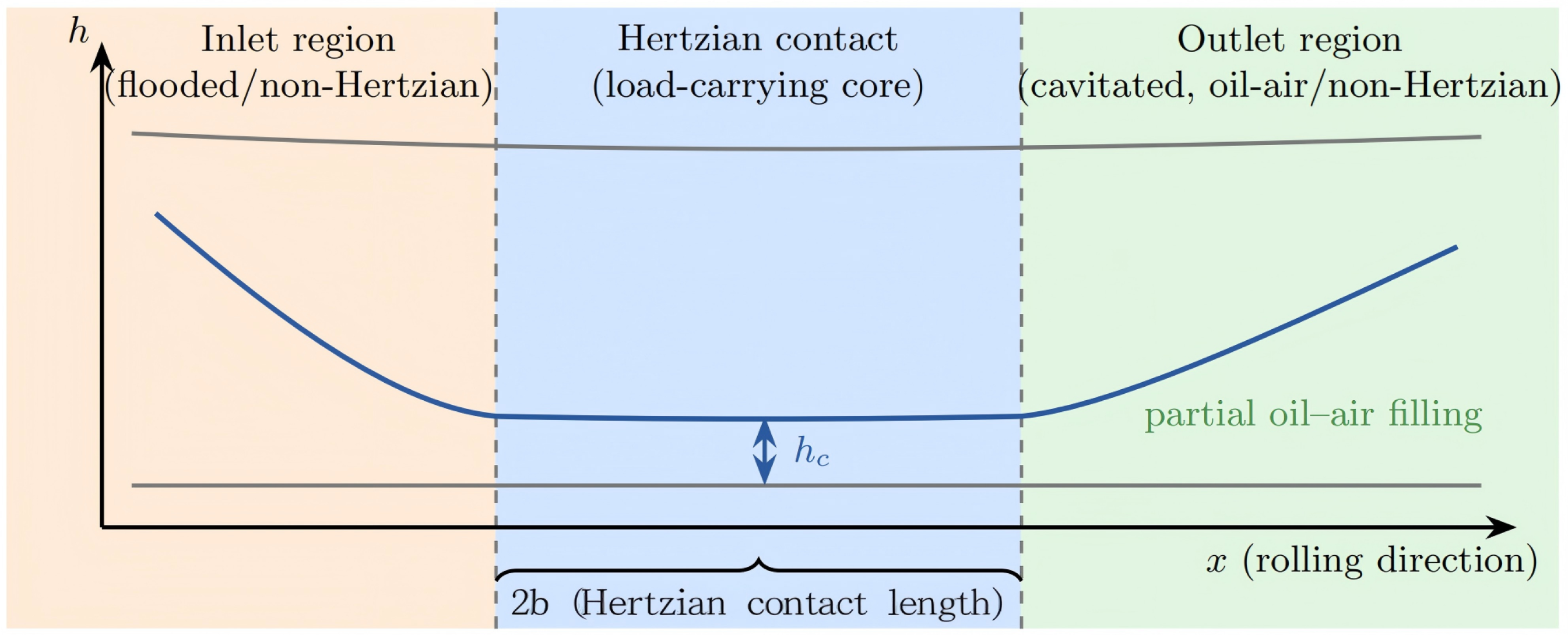
52]. Because capacitance scales inversely with local gap height, the measured signal is sensitive not only to the nominally load-carrying Hertzian region but also to surrounding non-Hertzian regions whose mechanical role is smaller but whose electrical contribution may still be substantial.
Figure 1 illustrates this geometric mismatch.
The measured capacitance can therefore be expressed, in a convenient generalized form for review purposes, as an area-integrated quantity over the electrically active region [
20,
21,
32],
Equation (
5) makes the basic inverse difficulty explicit: the measurement is global, whereas the film geometry is spatially distributed. A single measured capacitance cannot by itself identify a unique local film descriptor unless additional assumptions are introduced regarding the gap shape, the active area, or the relation between central and non-central film thickness [
10,
11,
12,
20,
21]. The key implication is therefore methodological: any method claiming local thickness from a single global capacitance must be judged primarily by the strength of its constraining assumptions.
In rolling bearings and similar components, this geometric difficulty is compounded by the presence of multiple contacts connected through series and parallel electrical pathways [
32,
33]. The problem is therefore not merely that real contacts are not parallel plates but that component-scale measurements integrate non-uniformity at more than one structural level.
2.3. Frequency Dependence and the Limits of Scalar Capacitance Interpretation
In practical measurements, the electrical response of a lubricated contact is commonly embedded in a broader impedance response. A convenient effective representation, consistent with standard impedance treatment and widely used low-order interpretations of lossy dielectric contacts, is [
36,
39,
53,
54]
where
C is the effective capacitance and
is the electrical conductance associated with leakage through the lubricant film, boundary layers, mixed phases, or conductive pathways. In practical grease-lubricated bearings,
should not be interpreted as a single material property of the base oil. It may represent an effective leakage contribution caused by polar additives, thickener-rich regions, adsorbed boundary layers, wear particles or contamination, oil–air interfaces, moisture, and intermittent asperity-scale conduction under thin-film or starved conditions. Therefore,
is best regarded as an operating-state-dependent effective conductance term in the local impedance model. Unless an explicit topology model is introduced, both quantities should be interpreted as effective and measurement-dependent.
The apparent capacitance inferred from electrical measurements is therefore frequency dependent and may be written as [
36,
53,
54]
A reported capacitance value is therefore meaningful only with reference to the excitation frequency or frequency range used to obtain it, and changes in apparent capacitance do not necessarily reflect changes in film geometry alone. They may also arise from leakage, interfacial polarization, dielectric loss, or changes in how the measurement circuit weights contact and parasitic branches.
In practice, the relative importance of the conductive term depends on lubricant type, filling state, contamination, temperature, and frequency. At low frequencies, especially under starved or grease-lubricated conditions, may become comparable to or larger than , in which case a scalar-capacitance interpretation becomes unreliable. A practical criterion for capacitively dominated interpretation is therefore not the frequency value alone but whether the measured phase angle remains close to that of a predominantly capacitive response and whether the inferred capacitance is stable with respect to modest frequency variation. Equivalently, the condition provides a useful first check, although the acceptable margin depends on the required accuracy and on the uncertainty of the background/parasitic compensation.
At lower frequencies, leakage and polarization processes may dominate the apparent response; at higher frequencies, the response may become more strongly dielectric but only up to the point where simple lumped-element descriptions remain valid [
36,
39,
53,
54]. The practical value of multi-frequency and broadband measurements follows directly from this limitation: frequency variation can provide additional constraints that help distinguish geometric effects from loss, leakage, and parasitic contributions.
2.4. State-Dependent Dielectric Response and Effective Permittivity
Another major difficulty is that the dielectric response entering electrical reconstruction is generally state-dependent. In lubricated contacts, the relevant electrical medium is often not a homogeneous bulk liquid but a confined, evolving, and sometimes multiphase region whose response depends on pressure, temperature, molecular polarity, interfacial structure, and phase composition [
20,
41,
50]. In grease-lubricated and starved contacts, oil bleeding, oil–air mixtures, cavitation, and boundary layers may coexist within the electrically active region, so the quantity entering the electrical model is better regarded as an effective response than as a fixed intrinsic material constant [
25,
42,
55].
This point is consistent with classical dielectric theory for heterogeneous media, where charge accumulation at phase boundaries gives rise to Maxwell–Wagner-type polarization [
56,
57,
58]. For the present review, however, the main implication is methodological: capacitance-based film thickness reconstruction usually does not have direct access to a uniquely known in situ permittivity. In the present context, this mechanism is relevant because the electrically active region in a grease-lubricated or starved contact may contain base oil, thickener fragments, air pockets, cavitated regions, adsorbed boundary layers, and possibly trace moisture or debris. Interfaces between these phases can store charge and alter the apparent dielectric response measured at the terminals. As a result, an inferred increase or decrease in effective permittivity may reflect changes in phase distribution or interfacial polarization rather than a change in the intrinsic permittivity of the lubricant alone.
For this reason, it is useful to distinguish between “bulk permittivity” and “effective permittivity”. The former refers to a material property measured under bulk-fluid conditions, whereas the latter is an operational parameter associated with the electrically active region under a specified measurement condition. If bulk and effective permittivity differ substantially, an apparent change in reconstructed film thickness may partly reflect dielectric variation rather than geometry alone. Dielectric behavior should therefore be treated as a primary source of uncertainty in capacitance-based reconstruction.
2.5. Capacitance Measurement as a Network-Embedded Inverse Problem
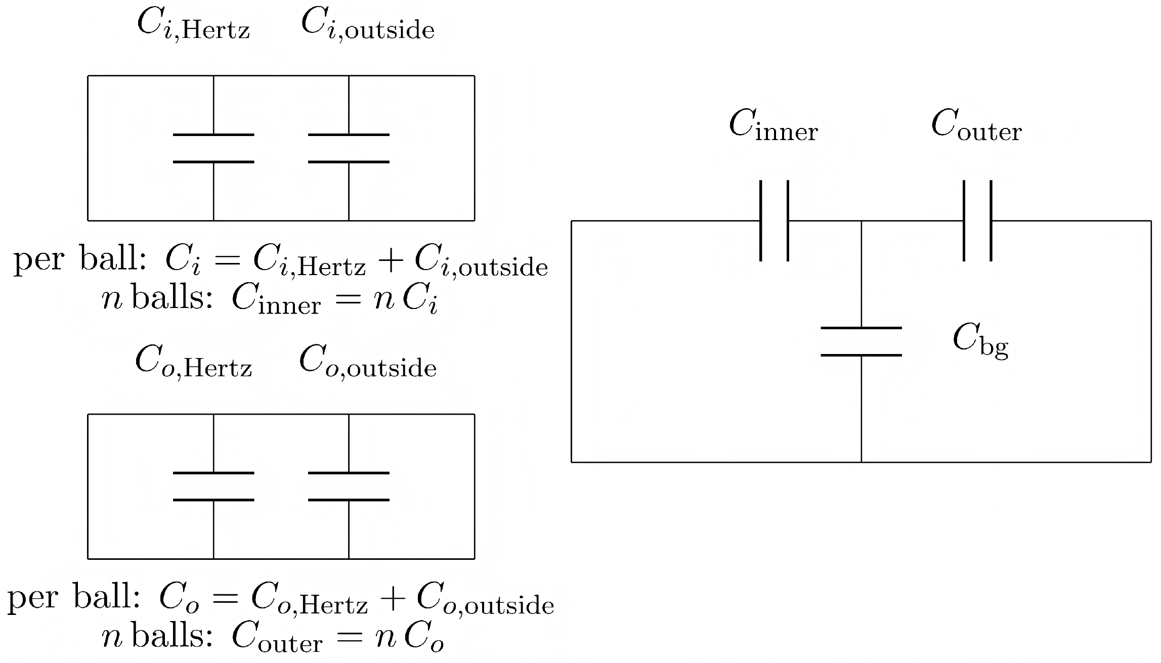
Taken together, the preceding subsections show that capacitance-based film thickness determination is fundamentally a network-embedded inverse problem. The unknown tribological state is spatially distributed, but the measurement is global; the dielectric response is state-dependent but usually not known independently; and the measured signal is conditioned by both frequency and electrical topology. These features become especially clear in rolling bearings, where the measured response is a reduction in multiple inner- and outer-ring contacts together with background branches.
Figure 2 illustrates this point schematically. For each rolling element, the inner- and outer-ring contacts can be decomposed into Hertzian and surrounding non-Hertzian contributions, such that
and
. These per-ball contributions are then accumulated over the electrically active rolling elements to form equivalent branches, which are measured together with a background branch
.
An important implication is that a rolling bearing should not, in general, be characterized by a single unique film thickness. Inner- and outer-ring contacts may differ in kinematics, load distribution, starvation state, and thermal condition, so the more physically meaningful inference target is often branch-resolved, for example in terms of inner- and outer-ring film descriptors and , rather than one bearing-wide scalar thickness. A single reported bearing “film thickness” is therefore most defensible only when it is clearly defined as an equivalent indicator resulting from a specified network reduction.
The measured capacitance is therefore not the response of a single local film thickness but the topology-dependent reduction in multiple contact and parasitic contributions. Similar electrical signals may arise from different combinations of Hertzian film thickness, non-Hertzian gap geometry, dielectric response, contact multiplicity, and background coupling. Meaningful interpretation therefore requires a forward model that maps assumptions about geometry, dielectric state, filling condition, and network topology to a measurable electrical quantity. The corresponding inverse problem is then approached by constraining unknown parameters such as film thickness, effective permittivity, loss descriptors, starvation or filling factors, and parasitic terms. These constraints reappear later as methodological differences in what individual approaches hold fixed, what they estimate explicitly, and what uncertainty is absorbed into the reported film thickness quantity.
4. Methodological Landscape of Modern Capacitance-Based Approaches
Modern capacitance-based film thickness methods differ less in whether they use electrical measurements than in how they constrain four coupled sources of uncertainty: contact-scale film geometry, dielectric response, electrical topology, and parasitic/background contributions. For this reason, the main methodological divide is not simply between capacitance and impedance measurements but between routes that leave ambiguity largely implicit and routes that attempt to constrain it more explicitly through geometry-aware modeling, dielectric treatment, topology-consistent reduction, frequency-domain information, or additional physical priors.
This distinction also means that similarly named “film thickness” outputs need not represent the same inferential object. Depending on the assumptions imposed, a reported value may function as an equivalent indicator, a contact-scale proxy, a branch-resolved component-scale quantity, or a jointly inferred state descriptor. The comparison developed in this section therefore follows four recurring questions: what electrical observable is measured, what quantities are prescribed a priori, what quantities are inferred from the data, and what validation basis supports that inference.
Table 2 provides a compact alignment framework for the comparisons that follow. Its purpose is to avoid a common interpretive error in the literature: treating all reported “film thickness” values as though they had the same physical status. In practice, different observables, model assumptions, and validation strategies support different levels of claim.
4.1. Classification by Electrical Observable: Single-Frequency Capacitance, Impedance-Aware Interpretation, and Broadband Response
A useful way to classify modern electrical film thickness methods is by the informational content of the measured observable. The earliest and still most common route uses single-frequency capacitance, in which the instrument output is reduced to an effective capacitance and then related to film thickness through a forward model. Its main advantages are simplicity, low instrumentation burden, and practical applicability. Its principal limitation is weak identifiability: with only one effective scalar observable, geometric, dielectric, leakage, and parasitic effects are only weakly separated. For that reason, single-frequency capacitance is usually most defensible when the target is an equivalent or trend-level thickness indicator under relatively restrictive assumptions, rather than a uniquely resolved local film quantity.
A second route treats the measured response explicitly as a complex quantity,
or
, rather than as a scalar capacitance alone. This impedance-aware interpretation improves separation between dielectric storage, conductive leakage, and loss-related effects, especially under thin-film or mixed-dielectric conditions [
36,
39]. Relative to single-frequency methods, it offers stronger physical discrimination, but it also requires more explicit assumptions about circuit representation, usable frequency range, and parameter identifiability. In other words, it does not remove ambiguity automatically; it provides additional structure with which ambiguity can be redistributed more explicitly across model parameters.
A third route uses broadband or multi-frequency measurements, where the observable is the frequency response itself rather than a single capacitance value. The main value of this route is not merely a larger amount of data but a greater number of independent constraints in the measured response. This direction has become more visible in recent studies using electrical impedance spectroscopy for lubricated contacts with complex geometry and in realistic rolling-element configurations [
45]. Frequency-dependent behavior can help distinguish geometric film thickness effects from dielectric dispersion, conductive branches, and background capacitances [
45,
54,
69]. At the same time, the broader frequency window imposes a stricter burden on the model: a route that reproduces one apparent capacitance level may still fail to reproduce the measured spectrum. Broadband approaches are therefore methodologically stronger only when the adopted model remains physically interpretable across the fitted range and when the added parameters remain identifiable.
The practical distinction is thus not simply between scalar and spectral observables but between observables that weakly constrain the inverse problem and those that constrain it more explicitly. A single-frequency capacitance value may remain useful as an equivalent indicator, but it is generally insufficient for unique separation of geometric, dielectric, and parasitic effects once those contributions become comparable in magnitude.
4.2. Contact-Scale Modeling Strategies: Uniform-Gap, Region-Decomposed, and Distributed EHL-Informed Models
At the contact scale, modern capacitance-based models can be grouped into three broad levels: uniform-gap models, region-decomposed models, and distributed EHL-informed models. These routes differ mainly in how much geometric structure they retain between local gap physics and the final electrical observable, and therefore in how much of the local-to-global mismatch is made explicit rather than absorbed into an equivalent quantity.
The most idealized class retains the classical parallel-plate viewpoint, in which the lubricated conjunction is represented by a uniform dielectric gap. Such models are simple and historically important, but they neglect the strong spatial non-uniformity of EHL films and therefore provide only limited realism for quantitative reconstruction. In practical use, they are best interpreted as low-order approximations or equivalent-gap models rather than faithful contact representations. Their main utility lies in interpretive convenience; their main limitation is that geometric complexity is compressed into the reported thickness itself.
A second and highly influential class is based on region decomposition. Jablonka et al. introduced a framework in which the total capacitance of an EHL contact is expressed as the sum of contributions from the Hertzian contact region and the surrounding inlet and outlet zones [
32]. By combining capacitance measurements with independently predicted film thickness distributions, such approaches moved beyond purely empirical calibration and made the role of non-Hertzian regions explicit. Published comparisons under fully flooded conditions, including those reported by Jablonka [
70], show that capacitance-derived film thickness can reproduce overall contact-scale trends relative to optical interferometry and Hamrock–Dowson-type predictions, while still remaining sensitive to model partitioning and dielectric assignment.
The geometric basis of many modern models is the partition of the contact into inlet, Hertzian, and outlet zones. Under quasi-electrostatic conditions, the effective contact capacitance can be written, in a generalized region-aware form synthesizing the approaches of Jablonka and later bearing-scale extensions [
32,
36,
37], as
where
is the film thickness distribution,
is an effective permittivity, and
is the electrically active region. In region-based implementations, this is commonly reduced to
with the outlet term sometimes further divided into flooded and cavitated parts under starved conditions.
Region-decomposed models improve physical plausibility because they make off-Hertzian contributions explicit. However, they do not by themselves resolve non-uniqueness. Instead, they shift the dominant uncertainty toward region boundaries, active-area definition, and dielectric assignment. A third class retains local gap height and local dielectric state more explicitly within distributed EHL-informed models, often together with bearing-scale topology. These models offer greater physical fidelity, but they also sharpen the inverse problem rather than removing it. Once geometry is represented in more detail, uncertainty shifts toward dielectric treatment, electrically active area definition, parasitic compensation, and parameter identifiability.
Across these modeling routes, the main difference is not simply geometric realism but where uncertainty is located. Uniform-gap models compress most geometric complexity into an equivalent thickness, region-decomposed models make off-Hertzian contributions explicit but remain sensitive to region partition and dielectric assignment, and distributed EHL-informed models retain greater physical detail at the cost of sharper identifiability demands. The progression is therefore not a simple movement from less accurate to more accurate models but from less explicit to more explicit treatment of geometric and dielectric uncertainty.
4.3. Treatment of Dielectric Properties: Fixed, Identified, and Jointly Estimated Permittivity
Dielectric treatment is one of the clearest points of separation between weakly and strongly constrained methods. In the simplest route, the permittivity is fixed from bulk measurements or literature values. This is operationally convenient, but it shifts all mismatch between model and measurement into the reconstructed film thickness quantity. When confinement, mixed phases, interfacial polarization, or leakage alter the electrically relevant response, fixed-permittivity reconstruction can become systematically biased.
A more general description uses a complex, frequency-dependent permittivity as standard in dielectric spectroscopy [
53],
where
is the dielectric loss tangent. This form makes clear that an apparent “capacitance” obtained from frequency-dependent measurements may contain both storage and loss contributions.
From a methodological standpoint, dielectric treatment in recent studies falls into three broad classes: fixed permittivity, identified effective permittivity, and jointly estimated dielectric parameters. In the first, is prescribed. In the second, an effective permittivity is identified under controlled reference conditions and then used in subsequent reconstruction. In the third, dielectric parameters are treated as unknowns within the inverse problem together with film thickness- or starvation-related variables.
The need for the second and third routes follows from the fact that the dielectric parameter required in bearing-scale inference is rarely known in situ. This issue remains central in recent discussions of lubricated bearings as electrical elements within larger circuits and in newer bearing-scale interpretation frameworks [
46,
47]. Under thin-film, starved, or grease-lubricated conditions, the electrically relevant dielectric response may be altered by confinement, outlet-region oil–air mixing, leakage, and interfacial polarization [
32,
42,
50,
55].
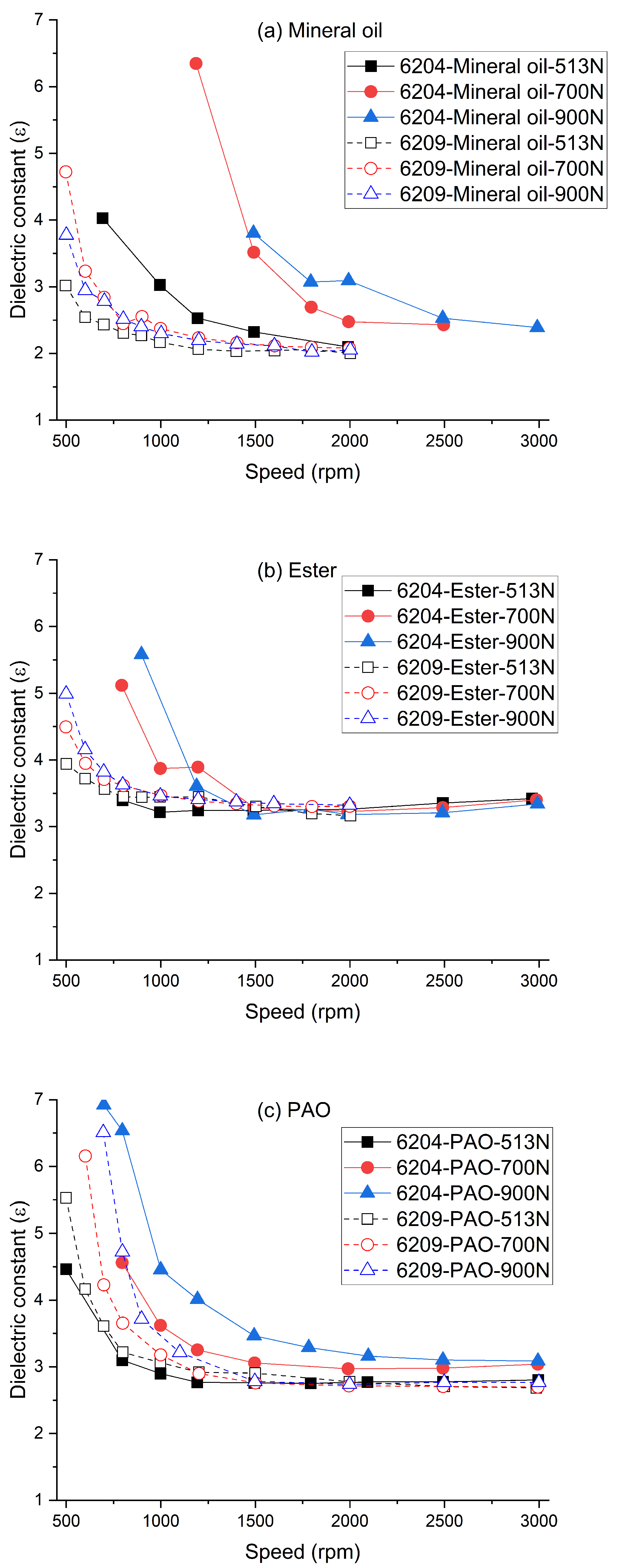
Figure 4 illustrates this point at bearing scale. For all three lubricants, the inferred
varies systematically with speed, load, and bearing type, with the strongest deviations generally appearing at lower speeds and higher loads. In the present review, such behavior is interpreted primarily as evidence that a fixed bulk dielectric input may become inadequate under practical operating conditions; it should not be read directly as proof of intrinsic material-property variation alone.
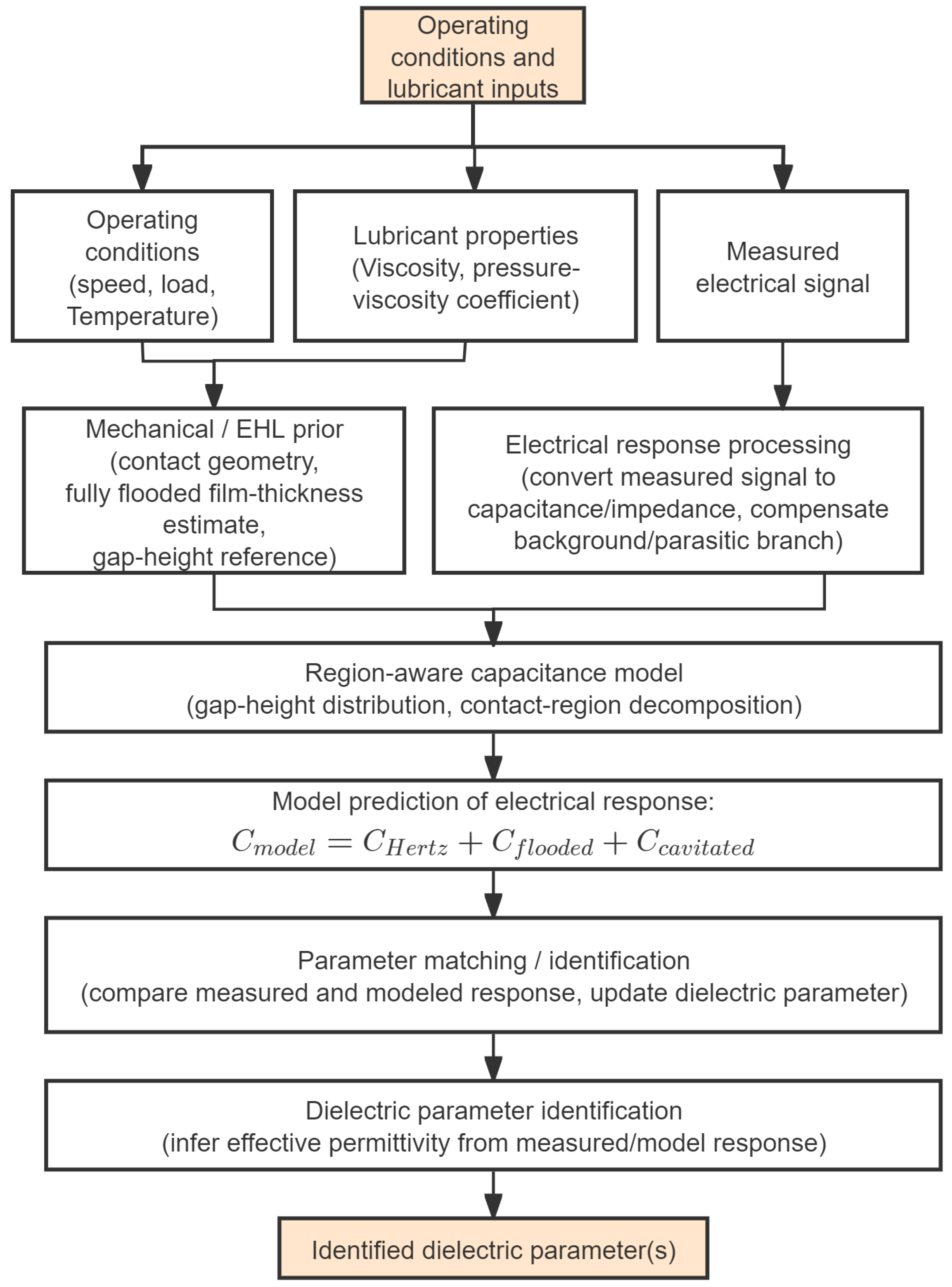
Figure 5 illustrates a generalized response to that difficulty. The workflow combines operating conditions, lubricant properties, the measured electrical signal, and an EHL-based mechanical model prior to defining a physically admissible gap-height reference. The processed electrical response is then evaluated using a region-aware capacitance model with background and parasitic compensation, and matching modeled and measured responses yields an effective dielectric parameter for subsequent use under more complex lubrication conditions.
A critical distinction follows from this point. If discrepancies between model and experiment arise from starvation, non-fully developed films, active-area mismatch, or simplified contact geometry, it is not physically rigorous to interpret the resulting fitted dielectric quantity as a material-property change alone. In such cases, a more defensible formulation is to separate the inverse problem into at least two components: a dielectric-response parameter and a geometry- or filling-related correction/state descriptor. The former may be identified under well-controlled reference conditions; the latter should account explicitly for departures from the reference regime.
A convenient way to express this separation is
where
denotes an operationally identified dielectric-response parameter,
is the calibrated background capacitance, and
is a correction/state factor accounting for deviations from the reference gap or filling condition in branch
k. In this form, dielectric identification and geometry/filling correction are kept conceptually distinct.
From an inverse-problem perspective, dielectric identification improves identifiability but does not eliminate ambiguity. Without independent constraints, a change in measured electrical response may still be attributed either to film geometry or to dielectric response . Effective permittivity is therefore best treated operationally, as a constrained state parameter within a specified model and operating window rather than as an independently validated property of the lubricated contact.
4.4. Bearing-/Component-Scale Electrical Network Models and Parasitic Compensation
In rolling bearings and other practical machine elements, the measured response reflects multiple lubricated contacts connected through the structure, together with parasitic contributions from fixtures, wiring, and non-contact regions. Modern models therefore represent the system as an electrical network of contact impedances and background branches [
33,
68]. At component scale, network reduction determines how local contact responses are weighted in the measured observable and therefore how much of the signal can be attributed to contact physics rather than structural embedding. It also determines whether the reported output corresponds to an inner-ring branch, an outer-ring branch, or only an equivalent bearing-level quantity. This network-embedded view is also consistent with recent studies that treat lubricated bearings explicitly as electrical elements within larger circuits rather than as isolated tribological contacts [
47].
Representative bearing-scale comparisons, including those reported by Jablonka [
70], show that capacitance-derived reconstructions can reproduce the expected increase in film thickness with entrainment speed and can, under suitable network assumptions, distinguish between inner- and outer-ring contact branches. At the same time, agreement with theoretical predictions should be interpreted mainly as support for trend consistency rather than as fully independent proof of absolute uniqueness, because the result still depends on branch partitioning, contact geometry assumptions, and background electrical treatment.
A compact network-level admittance representation, consistent with bearing-network treatments in the literature, is [
33,
36,
37,
54]
where
denotes topology-dependent series/parallel reduction,
is the number of electrically active contacts, and
lumps background and wiring parasitics. Each contact is then often parameterized, in effective form, as a lossy capacitor [
36,
37,
54],
where
is linked to film geometry and
denotes the electrical conductance of the
kth contact branch. In this form, the explicit frequency dependence of both
and
is retained at the notation level. In practice, however, the valid frequency range of a given empirical or semi-empirical model must be stated by the original study and should not be extrapolated automatically beyond that range. Schneider et al. further developed empirical and semi-analytical formulations relating measured bearing capacitance to the underlying film thickness distribution within individual contacts [
36,
37].
From a practical standpoint, background and parasitic calibration should be treated as an explicit experimental step rather than as an optional modeling refinement. If or is of the same order as the contact-related contribution, background subtraction or independent calibration should be performed before inverse interpretation.
Methodologically, the main benefit of explicit network modeling is clearer attribution of signal origin. The main risk is that topology assumptions themselves become part of the inverse problem. If the number of electrically active contacts, branch reduction, or background correction is poorly constrained, the inferred film thickness or effective permittivity may be biased even when the contact-scale model is otherwise reasonable. Where this is not controlled independently, the reported output is better regarded as topology-conditioned rather than as an intrinsic contact quantity.
4.5. Starvation, Grease Lubrication, and Transient Operating Conditions
A representative engineering example is a grease-lubricated deep-groove ball bearing operating under stepwise speed changes or repeated start–stop motion. During continuous running, the raceway track may become progressively depleted because the EHL contact consumes more oil than the surrounding grease can replenish. During standstill, part of the bled oil can flow back toward the track, so the film thickness immediately after restart may differ from that measured before stopping, even at the same nominal speed and load. In an electrical measurement, this history dependence appears not only as a change in film geometry but also as a change in the filling state and effective dielectric response of the electrically active region.
This example illustrates a broader limitation of classical capacitance-based interpretation under grease-lubricated and starved conditions. In such regimes, starvation, replenishment, and transient operation introduce coupled variations in film geometry, filling state, phase distribution, and dielectric environment [
43,
46,
48,
71,
72]. The inferential target therefore shifts from thickness alone toward a thickness-related state coupled to supply and dielectric behavior. In this regime, simplified geometry-only models may misattribute supply-driven or dielectric-driven changes to an apparent thickness signal.
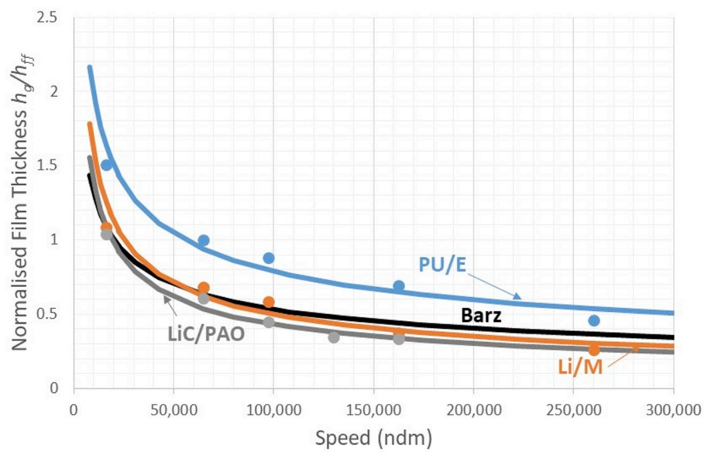
Two observations are particularly important. First, after prolonged running, grease-lubricated bearings commonly enter a starved regime in which normalized film thickness decreases with increasing speed, indicating that lubricant supply becomes progressively insufficient and can no longer be treated as a secondary correction.
Figure 6 illustrates this behavior [
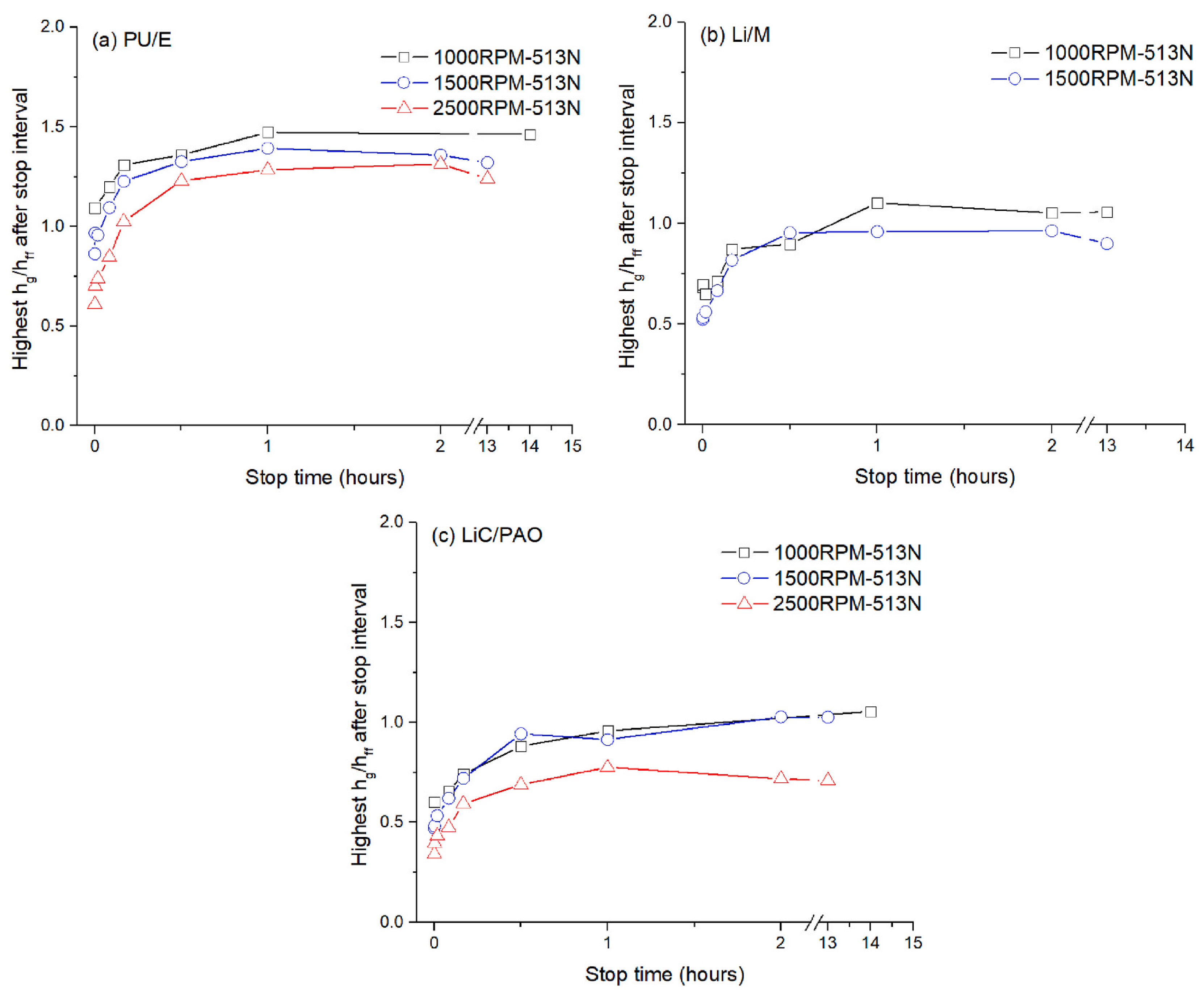
43]. Second, the electrical response is history-dependent: after a stop, the normalized film thickness measured immediately after restart increases with stop time before approaching a plateau, indicating progressive replenishment during standstill.
Figure 7 shows this transient behavior [
72]. Together, these results show that the same nominal operating point may correspond to different electrical responses depending on supply condition and prior operating history.
Additional studies further show that starvation behavior can be collapsed using local contact parameters such as
, indicating that replenishment is governed more by local supply conditions than by speed alone, and that initial grease filling can also modify starvation severity [
44,
71]. The main review-level point, however, is not the detailed form of each trend but the methodological consequence: in grease-bearing conditions, the same nominal capacitance shift may correspond to thickness change, filling change, dielectric change, or some combination of all three.
A convenient generalized way to incorporate starvation into electrical interpretation is to introduce a filling-factor field
, following the physical logic of starvation-aware electrical models [
42,
43,
71,
72]:
where
is the confined-oil permittivity and
represents an effective permittivity for oil–air or cavitated regions. Shetty et al. developed an improved electrical capacitance method that explicitly accounts for starvation by coupling contact-scale modeling with bearing-scale electrical networks [
42]. Modern inversions are therefore often formulated, at a generic review-framework level, as constrained optimization problems [
42,
54,
69],
where
may include film thickness, starvation, and dielectric parameters, while
imposes physical bounds such as positivity, plausible permittivity ranges, and temporal smoothness.
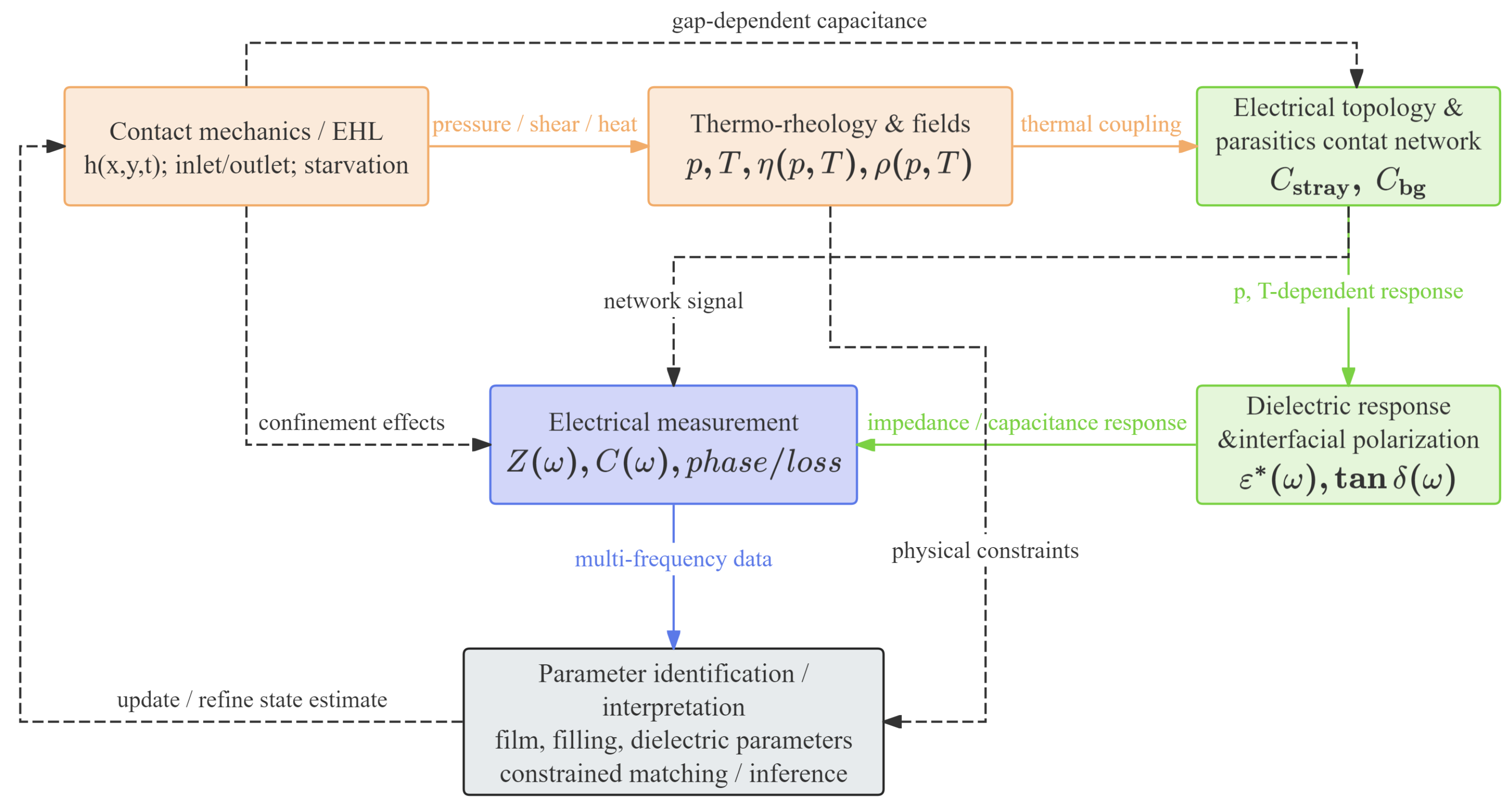
Figure 8 summarizes the corresponding electromechanical interpretation framework. The measured electrical response is jointly shaped by contact mechanics and EHL film geometry, thermo-rheological state, dielectric response, and bearing-level electrical topology with parasitic branches. The lower identification block emphasizes that recent reconstruction routes are therefore not single-parameter calibrations but constrained inference procedures in which film-, filling-, and dielectric-related parameters must be matched simultaneously to electrical data.
In practice, inverse formulations often attempt to constrain several parameter classes simultaneously, including a reference film thickness measure, an effective permittivity, dielectric loss descriptors, starvation- or filling-related variables, and parasitic/background terms. Different parts of the electrical response constrain these quantities differently, so successful inversion depends not only on model form but also on whether the measured data contain enough independent information to separate the targeted unknowns. A common failure mode is underdetermination masked by apparently good fit quality.
4.6. Comparative Summary of Modern Methodological Routes
The comparisons above make one point explicit: modern capacitance-based methods should not be compared only by instrumentation but by inferential structure. In particular, four questions need to be aligned before values reported by different studies can be compared meaningfully: what was measured, what was assumed known, what was actually inferred, and what validation basis supports that inference.
Table 3 highlights a point that deserves emphasis: the phrase “film thickness” is not methodologically uniform across these routes. Depending on the assumptions imposed, the reported quantity may function as an equivalent indicator, a contact-scale proxy, a branch-resolved bearing quantity, or a jointly inferred state descriptor. Comparing values across studies without first aligning inferential target, prescribed assumptions, and validation basis is therefore potentially misleading.
Although much recent development has focused on rolling bearings, similar interpretive issues arise in gears, journal bearings, piston-ring assemblies, and other machine elements, where non-uniform film geometry, dielectric uncertainty, dynamic loading, and parasitic contributions likewise shape the measured response [
18,
22]. The broader point is therefore not that one universal model applies across all components but that the same interpretive dimensions recur across them, including the nature of the measured observable, the assumptions imposed a priori, the quantity actually inferred, and the independent evidence available to support that inference. Although these interpretive questions arise across lubricated machine elements, the most explicit methodological development has occurred in rolling bearings, where multi-contact topology, grease lubrication, and starvation effects are especially well documented. Similar impedance-aware interpretation strategies are beginning to extend beyond bearings into other machine-element configurations.
4.7. Uncertainty, Validation, and Reporting Considerations
A useful way to make the uncertainty discussion operational is to distinguish four broad levels of evidential claim. Trend-level evidence supports the use of capacitance-derived quantities as monotonic indicators of lubrication-state change but not as unique film thickness estimates. Proxy-level evidence supports a model-conditioned contact-scale quantity whose physical meaning depends on region partition, dielectric assignment, and mechanical priors. Branch-level evidence supports separation of different contacts within a component-scale network but still remains conditional on topology and background treatment. Joint-state inference evidence is the strongest and most demanding level: it refers to studies that attempt simultaneous inference of film-, dielectric-, and filling-related parameters from richer observables such as broadband impedance spectra or transient responses.
Under this scheme, a study based only on single-frequency capacitance measurements and supported mainly by trend agreement with EHL theory would usually fall at the trend-level evidence category, or at most at the lower end of proxy-level evidence if a region-aware physical model is also imposed. Its main limitation is that such evidence is generally insufficient to support a claim of absolute local film thickness measurement, because geometry, dielectric response, and parasitic contributions remain only weakly separated.
Modern capacitance-based methods have become more physically realistic but also more explicit about uncertainty and identifiability limits. A first major difficulty is geometry–dielectric non-uniqueness: similar electrical signals may arise from different combinations of film thickness, dielectric response, leakage, and filling state. A second is parasitic and topology uncertainty: the measured signal is rarely generated by the lubricated contact alone. Wiring, shielding, fixtures, and non-contact regions may contribute capacitances comparable to the contact-related signal, while different assumptions about electrically active contacts and network reduction may change the inferred film thickness or effective permittivity [
33,
54,
69].
Table 4 has introduced the main uncertainty and identifiability challenges in electrical film thickness reconstruction.
Bandwidth introduces a further constraint. At low frequencies, leakage and interfacial polarization may dominate the apparent capacitance; at sufficiently high frequencies, lead inductance, phase delays, and distributed effects may invalidate simple lumped-element models [
54]. At the same time, electrical measurements remain global observables, whereas the lubrication state is spatially heterogeneous and often time dependent. Even region-decomposed and distributed models do not remove this mismatch; they only constrain it more explicitly [
32,
36,
70].
Validation is correspondingly difficult under realistic lubrication conditions. Optical interferometry remains a powerful benchmark at contact scale [
10,
11,
12], and recent direct optical work in rolling bearings further underscores both the value and rarity of such benchmark data under realistic grease-lubricated conditions [
48]. As a result, many reported reconstructions are validated only against EHL predictions, other indirect methods, or limited reference conditions. Such comparisons are useful, but they do not necessarily show that film geometry has been cleanly separated from dielectric variation, parasitics, or starvation-related filling effects [
37,
42,
43,
44,
46,
48,
71]. In many cases, trend agreement is easier to establish than absolute quantitative uniqueness.
These limitations arise from different sources and should not be treated as a single class of measurement error. Some reflect instrumental uncertainty, others incomplete observability, model-form approximation, topology uncertainty, or validation difficulty under realistic operating conditions. Collapsing them all into “measurement error” obscures the main methodological challenge, which is not only noise but interpretive ambiguity.
These considerations also affect reporting practice. Quantities labeled simply as “film thickness” may correspond to different observables, dielectric assumptions, topology reductions, and levels of parasitic compensation. For meaningful comparison across studies, authors should state clearly the measured observable, excitation frequency range, dielectric treatment, parasitic-compensation strategy, target of inference, quantities prescribed a priori, validation basis, and the key bounds or regularization assumptions used in inverse formulations.
Taken together, modern capacitance-based methods represent a transition from empirical electrical indicators toward more strongly constrained electromechanical inference tools. Their main differences lie not only in the observable used but also in the treatment of geometry, dielectric response, topology, starvation, and parasitic effects. Progress depends not merely on adding model complexity but on improving identifiability, validation strength, and reporting transparency under realistic lubrication conditions.
4.8. Practical Interpretation and Reporting Guidance
Building on the evidential levels and uncertainty sources discussed above, this subsection translates the interpretation framework into reporting guidance. The purpose is not to introduce another classification scheme but to specify the minimum information needed for readers to judge the physical status of a capacitance-derived film thickness result.
First, background and parasitic capacitances should be measured or calibrated before inverse interpretation. These contributions should not be left implicit when they are of the same order as the contact-related signal. Second, the electrical topology of the system should be stated explicitly, including whether the reported quantity is contact-scale, branch-resolved, or only an equivalent component-scale indicator. Third, the dielectric treatment should be declared clearly: authors should distinguish independently measured bulk properties from model-conditioned identified parameters. Fourth, where starvation, replenishment, or mixed filling are relevant, these should be represented explicitly through filling/state descriptors rather than absorbed silently into dielectric fitting. Fifth, the reported film thickness quantity should be named according to its actual inferential status, for example equivalent indicator, contact-scale proxy, branch-resolved estimate, or jointly inferred state descriptor.
In practical bearing measurements, the following reporting items are therefore recommended: measured observable (C, Y, or ), excitation frequency or bandwidth, background-calibration procedure, assumed electrical topology, geometric/contact model, dielectric treatment, whether inner- and outer-ring branches are separated, whether starvation/filling effects are modeled explicitly, and the validation basis used to support the reported inference.
For practical implementation, the interpretation path may be summarized as follows: (1) measure the raw electrical response; (2) calibrate the background/parasitic branch; (3) define the network topology and the target of inference; (4) select a contact model consistent with the operating regime; (5) identify dielectric and state parameters under clearly stated constraints; and (6) report the inferred quantity together with its inferential status and validation basis.
To make this interpretation route more concrete, consider a bearing-scale measurement in which a raw capacitance signal
is first recorded. Before any film thickness-related interpretation is attempted, an independently calibrated background contribution
should be removed so that the corrected contact-related response is written as
If the corrected response is then interpreted using a simplified equivalent-gap model with a prescribed electrically active area
and an operational dielectric-response parameter
, an equivalent thickness indicator may be written as
Table 5 provides an illustrative tabulated case for bearings 6204 and 6209 at selected operating speeds. In this example, the identified dielectric constants are taken from the Ester dataset represented in
Figure 4. The Hamrock–Dowson (HD) fully flooded central film thickness is then used as the mechanical reference quantity, while the inverse film thickness is the thickness-related output obtained from the interpretation route discussed in this review. Presenting these quantities side by side makes the practical inference chain more explicit and avoids over-reading a very limited number of points as a fully established trend law. At the same time, this example should be read as an illustrative closure of the inference chain rather than as a full validation dataset, because the HD values are mechanical reference values and not independent optical benchmarks.
Several observations may be noted from
Table 5. First, for both bearings, the inverse film thickness increases with speed, consistent with the increase in the Hamrock–Dowson fully flooded central film thickness. This comparison suggests that the inverse output retains the expected first-order speed dependence of the lubrication state within the present illustrative case. Second, the inverse film thickness remains systematically higher than the HD central film thickness at all listed points. This difference is especially pronounced for bearing 6204 at 1000 rpm, where
, and it decreases as speed increases. For bearing 6209, the deviation is smaller overall, with
decreasing from about 1.12 at 1000 rpm to about 1.05 at 2000 rpm. However, these differences should not be interpreted as validation error in a narrow sense, because the two quantities are defined at different interpretive levels and are not independent benchmark measurements of the same physical observable.
This comparison clarifies an important methodological point. The inverse film thickness reported by an electrical interpretation route should not automatically be regarded as identical to the Hamrock–Dowson fully flooded central film thickness. The two quantities belong to different interpretive levels. The HD value is a mechanically defined reference descriptor under fully flooded assumptions, whereas the inverse value is the outcome of an electrical measurement conditioned by dielectric identification, background correction, contact modeling, and network reduction. Their difference therefore does not necessarily indicate error in a narrow instrumental sense; rather, it reflects the fact that the electrically inferred quantity is a model-conditioned thickness-related output rather than a direct one-to-one reading of the HD central film thickness. Moreover, the discrepancy between inverse and HD thickness should not be attributed to the identified dielectric parameter alone, because it may also reflect simplifications in contact modeling, active-area definition, background correction, network reduction, and the difference between an electrically inferred equivalent quantity and a mechanically defined central-film descriptor.
The comparison between bearings 6204 and 6209 is also consistent with this interpretation. The dielectric constant does not exhibit the same monotonic behavior as the film thickness quantities, and its variation alone does not determine the final inverse result. Instead, the final output depends on the full interpretation route, including the corrected electrical response, the adopted forward model, and the chosen inferential target. This is precisely why capacitance-based film thickness determination should be reported and interpreted as a constrained electromechanical inference problem rather than as a direct capacitance-to-thickness conversion.
This illustrative case is intentionally limited in scope. Its purpose is not to establish a universal quantitative law from a small number of points but to demonstrate the practical correspondence among dielectric identification, mechanical reference thickness, and inverse thickness-related output. In more realistic bearing-scale applications, the reported quantity may remain an equivalent indicator, a branch-resolved estimate, or a jointly inferred state descriptor rather than a uniquely determined local film thickness. Even so, presenting these quantities explicitly in one table helps make the inference chain more transparent and reduces the risk of over-interpreting electrically inferred thickness values. Within the evidential scheme adopted in this review, this illustrative case should be interpreted at most as proxy-level support for a model-conditioned thickness-related output, rather than as validation of a unique local film thickness measurement.
5. Conclusions
This review has argued that capacitance-based film thickness determination in lubricated machine elements is not a methodologically uniform conversion from capacitance to gap height. The measured electrical response is shaped jointly by film geometry, dielectric response, electrical topology, and parasitic/background contributions, so the meaning of a reported “film thickness” depends fundamentally on what is measured, what is prescribed, what is inferred, and what validation basis supports that inference.
A central conclusion is that dielectric quantities identified from bearing-scale measurements should not automatically be interpreted as intrinsic material properties. In many cases, they are better understood as operational parameters within a specified forward model and operating window. Where deviations from model predictions arise from starvation, geometry mismatch, filling effects, or unresolved topology, these effects should be represented explicitly rather than absorbed silently into dielectric fitting.
The review also shows that the most informative distinction among methods is inferential rather than purely instrumental. Some approaches support trend-level monitoring, some support physically informed contact-scale or branch-resolved proxies, and only the most strongly constrained methods can plausibly support partial joint inference of film-, filling-, and dielectric-related states. Even then, the resulting estimates remain conditional rather than absolute.
Future progress depends on four linked directions: stronger separation of dielectric and geometric uncertainties; more explicit treatment of branch-resolved and starvation-dependent states; wider use of multi-frequency and broadband observables; and more rigorous reporting of background calibration, topology assumptions, inferential target, and validation basis. Under these conditions, capacitance-based methods can be used more consistently as constrained electromechanical inference tools rather than as oversimplified direct thickness meters.