1. Introduction
The engineering problem of designing sealing assemblies in mechanical engineering stems from the inherent trade-off between compact dimensions and increased friction losses in mating components, and issues of durability of individual machine components. In modern turbomachinery and heavy engineering, sealing assemblies often occupy a disproportionately large volume compared to the working elements of the machine, and their considerable mass significantly affects the overall dimensional and weight characteristics of the equipment. Reducing the linear dimensions of seals is generally accompanied by a reduction in the number of sealing stages and an increase in friction on mating surfaces. The need to reduce the geometric parameters of seals while simultaneously improving their performance characteristics served as a driving force behind the development of magnetorheological seals (MRSs). The operating principle of MRS is based on retaining magnetorheological fluid in the gap between the rotor and the pole pieces of the magnetic circuit under the action of a volumetric magnetic force, thereby forming a stable fluid barrier [
1]. The main application areas of this type of seal include vacuum process equipment, instrumentation, mechanical engineering, and systems with elevated requirements for leak-tightness and precision of operation [
2,
3].
In one of the first works in the field of magnetic fluid seals, V. Kordonsky demonstrated that the use of magnetorheological fluid as a sealing medium opens fundamentally new possibilities related to the ability to regulate and control the friction torque and seal leakage [
4]. Detailed experimental studies by the same authors confirmed that the pressure differential in MRS under static conditions far exceeds that of classical designs with a significant reduction in the geometric dimensions of the sealing assembly [
5].
The principal operational characteristics of MRS that determine their field of application include friction torque, flow rate through the seal, and maximum sustainable pressure differential. Friction torque arises from the viscous resistance of the fluid as it is sheared between the rotating rotor and the stationary pole pieces [
6]. This parameter serves as a criterion for assessing the energy efficiency of the seal. In [
7] the authors formulated the design problem of a magnetorheological seal for laser beam directors as a parametric synthesis problem with two objectives: maximization of sealing pressure and minimization of rotational friction torque. Design variables included gap size, tooth width and height, groove width, number of stages, and pole shoe thickness. Selection of the optimal solution obtained through optimization reduced the friction torque by 0.04 N·m while simultaneously increasing the sealing pressure by 3 kPa. In [
8], devoted to the development of an MRF seal with reduced friction torque, a design solution was proposed based on operation in the pinch mode. The shaft was made of non-magnetic material, causing particle chains to orient parallel to the axis of rotation without being disrupted during seal operation. It was experimentally demonstrated that the friction torque of a pinch-type seal is approximately 12 N·mm at a current of 0.6 A and a speed of 1200 rpm, which is 10 times lower than that of a standard MRF seal, while the breakout pressure exceeds that of ferrofluid counterparts. In an earlier work by the same group, a seal concept based on the gradient-pinch mode was considered, combining the friction advantages of ferrofluid seals with the sealing capacity of MRF seals [
9]. Test results demonstrated a 20-fold reduction in friction torque compared to standard MRF seals, confirming the promise of this approach for precision applications. In a work devoted to the development of a magnetic fluid seal with a controllable magnetic field, it was shown that the use of an electromagnetic coil to regulate field intensity as a function of operating conditions reduces the start-up friction torque by more than 50% compared to classical designs [
10]. At the same time, the sealing capacity of the seal increased by 33%, reaching 0.24 MPa without the use of cooling equipment, which is particularly relevant for low-temperature conditions where conventional magnetic fluid seals are prone to start-up failure.
Another characteristic often considered as a performance criterion in parametric optimization is the leakage rate of the magnetorheological seal. The concept of a magnetorheological seal inherently assumes that the magnetorheological fluid forms a hermetic barrier, and when the maximum sustainable pressure is exceeded, temporary leakage of the sealed medium occurs followed by self-restoration of the sealing capacity [
11]. Thus, in [
1], devoted to the development of a “smart” seal for MRF-based actuators, a specific cause of carrier fluid leakage during prolonged idle periods was identified: sedimentation of particles leads to stratification of the MRF and subsequent leakage of the carrier fluid through the sealing zone. To address this phenomenon, the authors proposed an optimized magnetic seal design with an additional DC field that “freezes” the MRF in the gap, preventing particle separation and eliminating carrier fluid leakage during idle operation.
The use of different shaft and bearing materials also helps modify the characteristics of magnetic fluids. The paper [
12] presents an analysis of the tribometric characteristics of a plain bearing system lubricated with a ferrofluid (FF), taking into account different shaft materials. It was found that the EN-19 magnetic shaft provides better dimensional accuracy compared to the magnetic shaft made of low-carbon steel. Therefore, the EN-19 magnetic shaft was used in a brass bearing to evaluate various tribometric characteristics. Experimental results showed that the maximum pressure increased by up to 84% in the case of a bearing system based on FF compared to a system based on conventional lubrication. At the same time, in [
13] the authors found that the use of different materials for the bearing and shaft makes it possible to reduce the heating temperature of the ferromagnetic lubricating fluid.
Determination of the pressure sustained by the seal represents the most frequently solved design problem for devices of this type. This depends on the distribution of the magnetic field in the working gap, the rheological properties of the fluid, and the geometry of the magnetic circuit [
10,
14]. In [
15], devoted to modelling the sealing mechanism of an MRF seal, an analytical equation was proposed for calculating the sealing pressure, relating the shear stress of the magnetic fluid to the geometric parameters of the design through the magnetorheological effect. Experimental verification confirmed the validity of the proposed model and established that increasing the sealing pressure requires the development of magnetic fluids with higher shear stress. In [
16], a study of a seal based on micro/nanocomposite magnetorheological grease (MRG) with a pinch-mode pole piece showed that increasing the sealing gap predictably reduces the resistance pressure, whereas increasing the pole tooth width improves seal stability without increasing the total pressure. The magnetic field distribution in the gap was identified as the key factor governing seal performance. Theoretical calculations and experimental data are in good agreement, confirming the adequacy of the model employed. In the numerical study [
17] of a piston-type MRF seal using the finite element method (ANSYS), it was established that the sealing pressure increases monotonically with decreasing working gap. At a gap of 0.1 mm the pressure reaches 22.5 MPa, whereas at a gap of 0.4 mm it falls to 7.5 MPa. Parametric analysis also showed that the pressure increases with the number of magnetic sources (from 8 to 11) and pole tooth length, and that there exists an optimal ratio of permanent magnet height to length (1.4) at which the magnetic flux in the system is maximized. In [
18], devoted to an MRF seal for large-gap applications, a comparison of static and dynamic sealing performance at gaps of 0.1 and 0.4 mm and shear rates from 0.2 to 1.0 m/s demonstrated that MRF seals achieve higher pressure differentials than ferrofluid counterparts, with the advantage being especially pronounced at large gaps where ferrofluid seals become practically inoperable. The results confirm that MRF seals are a promising replacement for ferrofluid designs in dynamic systems with gap tolerances exceeding 0.3 mm. In [
19], devoted to the study of the influence of MRF composition on seal performance. It was shown that the presence of MRF in the gap itself significantly increases the magnetic flux density compared to an air gap, acting not as a passive but as an active element of the magnetic circuit. The sealing pressure increases nonlinearly with increasing particle volume fraction: for MRF with 4% particles it is 15.8 kPa, while for MRF with 28% particles it reaches 317 kPa, representing a nearly 20-fold increase, attributable to the simultaneous growth of both saturation magnetization and the yield stress of the fluid.
Surface roughness can also negatively affect the performance of bearings and seals. In [
20], researchers found that transverse surface roughness negatively affects bearing performance. However, ferrofluid lubrication based on the Jenkins model offers some potential for minimizing this negative effect while minimizing the sliding parameter. Also, the results presented in [
21] demonstrate that for electromagnetic fluids, the increase in load-bearing capacity due to magnetization depends only slightly on the influence of viscosity changes.
Analysis of the published literature identifies a number of unresolved problems in the field of MRS design. In particular, the flows arising in the seal gap generate hydrodynamic forces that must be accounted for within the framework of rotor dynamics analysis of systems with magnetorheological seals. It is worth noting that in the field of classical seal designs, a number of works can be identified that address hydrodynamic and aerodynamic processes in the seal gap [
22,
23]. Despite the substantial number of studies devoted to the sealing performance of magnetorheological seals, none of the published works have systematically investigated the hydrodynamic responses in magnetorheological fluid seals in the presence of rotor eccentricity as a function of angular velocity, eccentricity, and magnetic induction simultaneously. Furthermore, the influence of these responses on the stiffness and damping coefficients of the seal has not yet been quantitatively assessed. The present work addresses both of these gaps through a three-dimensional parametric finite element study. Thus, the novelty of the present work lies in the assessment of hydrodynamic forces arising in the fluid layer of magnetorheological seals at various rotor speeds, eccentricities, and magnetic field parameters.
2. Mathematical Modeling of Magnetorheological Seals
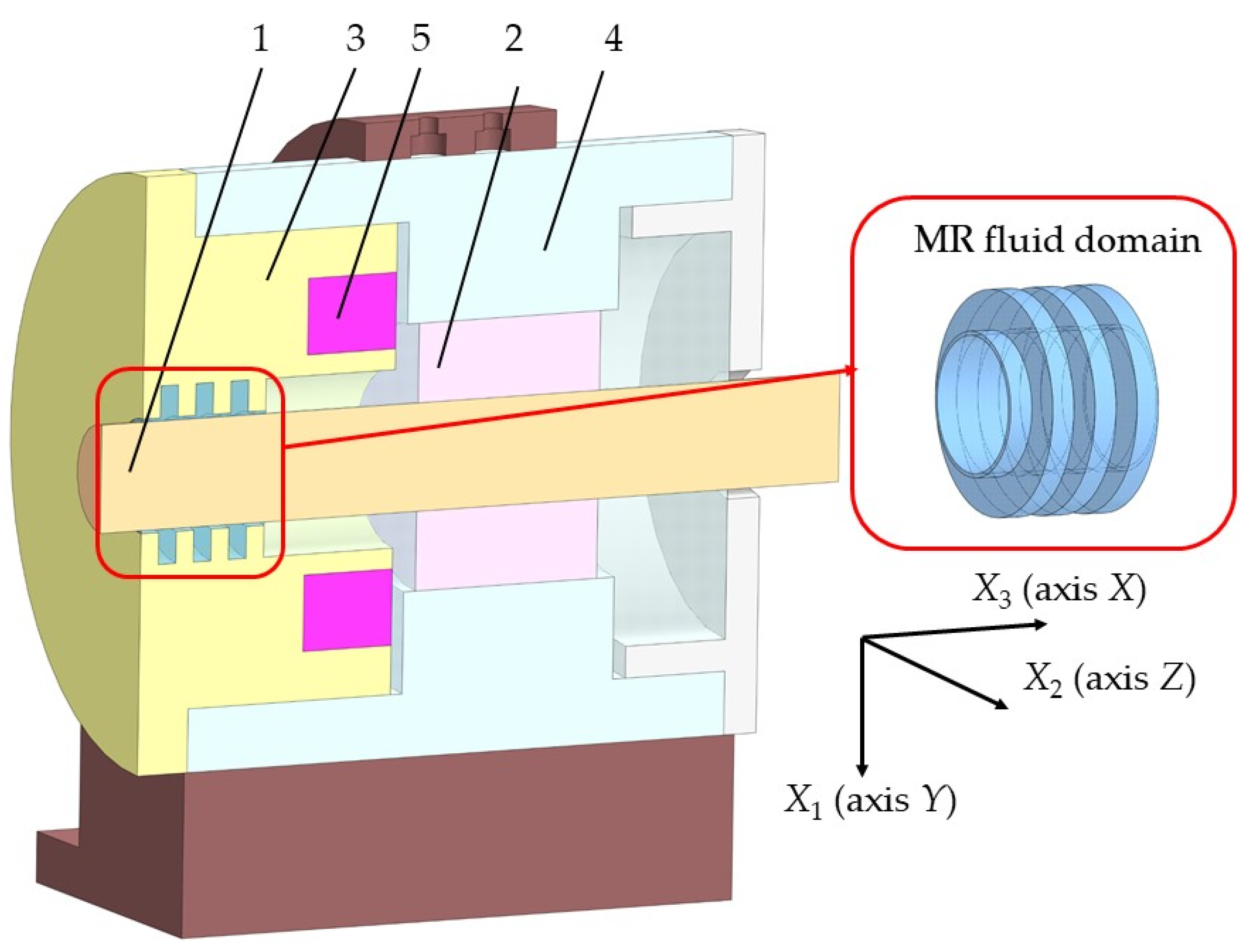
The subject of this study is the integral characteristics of a seal with a magnetorheological fluid exposed to a controlled magnetic field. The magnetorheological seal is a component of the support unit of a rotor system (
Figure 1). It consists of a rotating rotor (1), which is supported by a bearing (2), and a stationary cover (3) fixed to the housing (4). A permanent magnet (5) is inserted into a groove in the cover (3). The lubricant leaking from the ends of the journal bearing creates pressure in the internal region of the support unit. The magnetorheological fluid located in the gap between the rotor (1) and the cover (3) seals the lubricant of the journal bearing from the external environment.
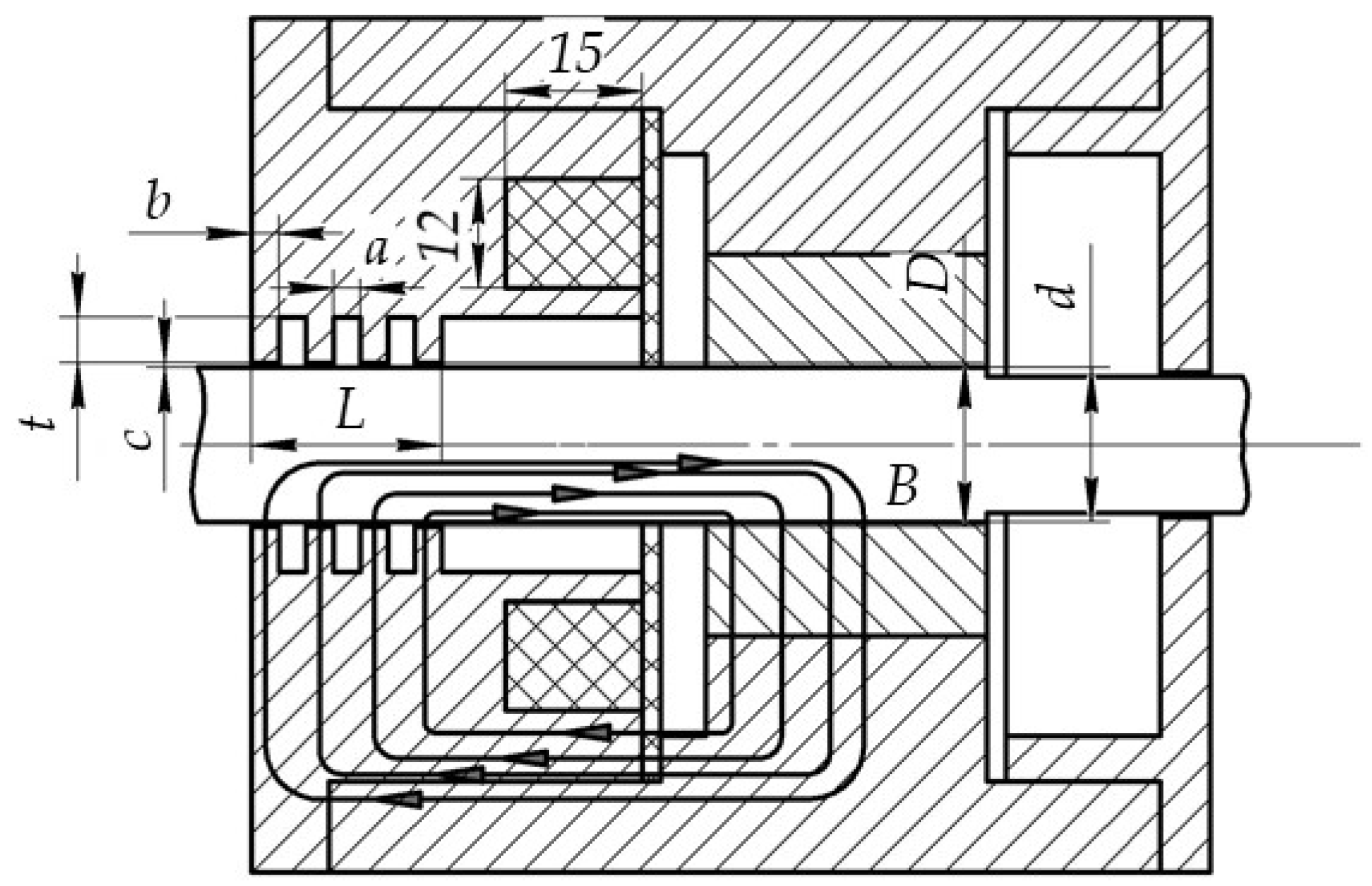
The considered seal geometry represents a gap between two non-coaxial circular cylinders of length
L. The outer cylinder (stator) has a diameter
D, while the inner cylinder (rotor) has a diameter
d. The stator contains several annular grooves, each with a diameter
D +
t and a length
b; the presence of these grooves forms magnetic field concentrators (
Figure 2). The source of the magnetic field is an annular electromagnet, which generates a closed magnetic field within the housing of the support unit. The magnetic flux lines pass through the rotor, the bearing sleeve, the stationary housing, and the cover containing the electromagnet. As the magnetic field crosses the gap region of the magnetorheological seal, the flux lines concentrate in the regions of the annular seal protrusions, thereby forming electromagnetic field concentrators.
In the considered problem, the
X-axis of the global coordinate system is aligned with the main axis of the support unit housing and is denoted in the calculations as the
X3 axis. The
Y-axis of the global coordinate system corresponds to the
X1 axis, while the
Z-axis corresponds to the
X2 axis. The rotor center is offset relative to the stator center by a distance
e along the
X1 axis:
The radial gap in the area of magnetic field concentrators is determined by the expression
The relative eccentricity, which characterizes the degree of misalignment, is equal to
The local gap in the domain of magnetic field concentrators, depending on the angular coordinate in the plane perpendicular to the axis of rotation, is described by the equation:
At the ends of the seal, a pressure drop is set (pin = 3 atm at the inlet, pout = 3 atm at the outlet), which ensures axial flow superimposed on the rotational flow.
The flow of the magnetic fluid in the gap is described by the Navier–Stokes equation and the continuity equation for an incompressible viscous fluid in a steady-state setting:
where
τ is the viscous stress tensor defined through the strain rate tensor:
The continuity equation (Equation (2)) expresses the law of conservation of mass for an incompressible fluid. It states that the net volumetric flow rate through any closed control surface is zero, meaning that fluid entering the region must be balanced by an equal outflow. For a magnetorheological fluid in a narrow seal gap, this condition ensures that the fluid cannot accumulate or deplete locally and is justified by the low compressibility of the oil-carrying fluid. The Navier–Stokes equation reflects the law of fluid motion. The left side of the equation represents the inertial (convective) acceleration of a fluid parcel. The first term on the right side (−∇p) is the net pressure force per unit volume acting on the fluid element, driving flow from high-pressure to low-pressure regions and ultimately responsible for the hydrodynamic load capacity of the seal. The second term (∇·τ) represents the divergence of the viscous stress tensor, accounting for the internal friction within the fluid. In the eccentric seal geometry, the asymmetric narrowing of the gap (h(θ) = c(1 + ε cosθ)) generates a circumferentially non-uniform pressure field that produces a net radial force on the rotor—the bearing load capacity.
The viscous stress tensor (Equation (6)) defines the viscous stress tensor for a generalized Newtonian fluid. The term [∇u + (∇u)G] is the rate-of-strain tensor (twice the symmetric part of the velocity gradient), which measures the local rate of deformation of fluid elements. The factor μeff is the effective (apparent) viscosity, which in the MRF case is a strongly nonlinear function of both the local shear rate and the local magnetic flux density. In the absence of a magnetic field (μeff = μp = const), this expression reduces to the standard Newtonian viscous stress tensor. The non-Newtonian characteristic of MRF is entirely captured through the field- and shear-rate dependence of μeff.
A no-slip condition is specified on the rotor surface (the rotating inner cylinder), taking rotation into account. With the rotation axis
X and the rotor offset by a value
e along the
Y axis, the velocity at the rotor boundary is specified as
This is the no-slip (adhesion) condition on the surface of the rotating rotor. It states that the fluid in direct contact with the rotor surface moves with the same velocity as the rotor surface itself. There is no relative sliding between the fluid and the solid boundary. The velocity field corresponds to rigid-body rotation about the rotor’s own axis (which is displaced by −e from the stator axis along Y): the circumferential velocity magnitude at the rotor surface equals ωR1 = 200 × 0.0195 = 3.9 m/s. The no-slip condition is the standard assumption for viscous flow and is well validated for Newtonian and non-Newtonian fluids at the shear rates encountered in this problem.
On the surface of the stator (stationary outer surface),
This is the no-slip condition on the stationary stator surface. It states that the fluid in contact with the outer cylinder is at rest. Physically, the viscous fluid “adheres” to the stator wall and cannot slip along it. This condition, together with the rotating wall condition (Equation (8)), generates the circumferential velocity gradient that drives the Couette flow component of the motion and produces the hydrodynamic shear stresses responsible for friction torque. The combination of the two no-slip conditions also ensures that the hydrodynamic pressure field (and therefore the load capacity) is driven entirely by the rotor rotation and the eccentricity of the gap geometry.
Pressures are specified on the end surfaces:
These Dirichlet pressure boundary conditions prescribe the absolute pressure at the axial entry and exit faces of the seal, creating a pressure differential Δp = 2 bar that drives a Poiseuille-type axial flow through the gap. Physically, this models the operational condition in which the high-pressure side of the machine (e.g., the pressurized chamber of a turbomachine) is at 3 bar and the low-pressure side (atmosphere or a drain cavity) is at 1 bar. The resulting axial flow constitutes the “leakage” through the seal; its magnitude is one of the key performance indicators of the sealing system. The pressure conditions are imposed as Dirichlet (essential) boundary conditions on the velocity–pressure formulation of the Navier–Stokes equations, and the axial velocity field ux(y, z) is determined as part of the solution.
For flow in the gap between rotating cylinders (Couette flow), the Reynolds number is determined by the rotor’s peripheral speed and the gap width:
Substitution of the maximum values of the parameters (
ω = 400 rad/s, without magnetic field) shows that the flow is purely laminar in nature:
A magnetorheological fluid under the influence of a magnetic field exhibits viscoplastic properties described by the Bingham model [
24]. This two-branch model describes the viscoplastic (Bingham) behavior of MRF. Below the field-dependent yield stress
τy(
B), the fluid behaves as a rigid solid: no flow occurs and the material transmits stress without deformation. This regime physically corresponds to the formation of a “solid core” zone in the narrow-gap region where the magnetic force chains are strong enough to resist the applied shear. Above the yield stress, the fluid flows with an apparent viscosity
μeff =
μp +
τy/
, which exceeds the plastic viscosity
μp by the Bingham contribution
τy/
. The Bingham number
Bn =
τy/(
μp∙
) quantifies the ratio of yield to viscous stresses:
Bn ≫ 1 indicates a predominantly plastic regime (field-dominated), while
Bn ≪ 1 corresponds to nearly Newtonian flow. The flow condition and the expression for stresses have the form
where
is the invariant of the strain rate tensor:
This is the second invariant of the rate-of-strain tensor, which provides a scalar measure of the local rate of deformation that is independent of the coordinate system. It reduces to the simple shear rate |du/dy| in a unidirectional shear flow. In the three-dimensional eccentric gap geometry, all six independent components of the strain-rate tensor contribute, reflecting the combination of circumferential shear (driven by rotor rotation), radial shear (driven by the eccentricity-induced pressure gradient), and axial shear (driven by the pressure differential Δp = 2 bar between the seal faces). The use of the invariant ensures frame-indifferent (objective) rheological behavior.
The components of the strain rate tensor are determined by the expression:
The classical Bingham model has a discontinuity at
= 0, which complicates the numerical solution (the Jacobian is undefined). The Papanastasiou regularization replaces this discontinuity with a smooth exponential approximation. The parameter
m [s] controls the sharpness of the transition. In practice,
m = 2–20 s is used: smaller values improve solver convergence at the cost of accuracy, while larger values reproduce the sharp yield threshold more faithfully. The physical interpretation is that m represents the characteristic relaxation time over which the fluid transitions from solid-like to liquid-like behavior. Papanastasiou regularization is used [
25], which replaces the discontinuous dependence with a continuous one.
At m ≫ 1, Equation (15) approaches the classical Bingham model. At m ≪ 1, the fluid behaves like a solid with high effective viscosity.
The Bingham number, which characterizes the relative role of the magnetically induced yield strength compared to viscous stresses, is defined as
At
Bn ≫ 1, the magnetorheological fluid in the high-magnetic-field zone practically freezes, which leads to a sharp increase in the load force and a decrease in leakage. The data sheet for Lord Corp MRF-132DG magnetorheological fluid [
26] is used as reference data (density, viscosity without a magnetic field, yield strength) for the magnetorheological fluid.
The mathematical model of the magnetic field for a stationary magnetic field in the gap of a magnetorheological seal is described by Maxwell’s equations [
27]:
These are the two governing equations of static magnetic fields. The first states that the curl of the magnetic field intensity H is equal to the free current density Je. In the present model, no free currents flow through the MRF; the field is generated by boundary conditions on the outer cylinder representing an externally applied source. The second equation states that magnetic flux lines form closed loops with no sources or sinks. There are no magnetic monopoles. This condition ensures conservation of magnetic flux through any closed surface and is what produces the B ~ 1/r dependence in the cylindrical gap geometry.
Through the vector potential
A (
B = ∇ ×
A) the equation takes the form
Introducing the vector potential A automatically satisfies ∇·B = 0 and reduces the system to a single second-order PDE. Physically, A represents the circulation of magnetic flux per unit length and plays a role analogous to the stream function in fluid mechanics. The use of A as the primary unknown in the finite element solution ensures that magnetic flux is exactly conserved at the discrete level. The Coulomb gauge (∇·A = 0) is imposed to ensure uniqueness of the solution.
The dependence of the relative magnetic permeability of the magnetic field on the field strength is described by the Fröhlich–Kennelly model [
28]:
This model takes into account magnetization saturation at high H values and provides a smooth transition from the initial permeability µr0 to unity at saturation. This rational approximation describes the saturation of relative magnetic permeability with increasing field intensity. It is derived from the Langevin model of paramagnetic saturation, adapted for concentrated ferrofluid suspensions. At H = 0 the permeability equals the initial value µr0. As H → ∞, µr → 1, corresponding to the saturation of magnetization at Ms. The hyperbolic form ensures a smooth, monotonically decreasing permeability without the abrupt transitions that would cause numerical instability. The parameter Ms physically represents the maximum achievable magnetization of the MRF when all iron particles are fully aligned with the external field.
The yield strength of a magnetorheological fluid depends on the local magnetic induction. The following saturation approximation is used [
29]:
This hyperbolic saturation model links the field-induced yield stress to the local magnetic flux density. Physically, the yield stress arises because the external field aligns iron particles into chain-like structures that resist shear deformation. At low fields the chains are short and easily broken (linear regime); at high fields the chains span the full gap width and the yield stress saturates at
τy0 as no further particle alignment is possible. The parameter
Bsat = 0.15 T represents the field at which 50% of the maximum yield stress is achieved, and is related to the coercivity and anisotropy of the iron particles. This model is consistent with the experimentally measured
τy(
B) curves for Lord MRF-132DG reported in the literature. The interaction between the flow velocity and the magnetic field is characterized by the magnetic Reynolds number [
30]:
Since the electrical conductivity of a magnetorheological fluid is extremely low (
σ ~
S/m), and the condition
Rem ≪ 1 is satisfied, there is no feedback effect of the flow on the magnetic field. This allows for the use of a one-way coupling of the magnetic field and laminar flow calculation problems:
In the rarefied flow region (on the side of the maximum clearance), the pressure can drop below the saturation pressure of the liquid, which corresponds to cavitation conditions. To take this effect into account when calculating seal reaction forces, a barotropic cavitation model is used [
31]:
The numerical solution of the problem was performed in Comsol Multiphysics using the finite element method. The Magnetic Fields interface (AC/DC Module) was used to calculate the magnetic field. For one-way coupling, the field was calculated using Equations (17) and (18), which were then used to calculate the effective viscosity (Equation (15)). The nonlinear viscosity µeff was transferred to the Navier–Stokes equations in the Laminar Flow solver (CFD Module) via a user-defined variable dependent on the local value of |B|. For the full electromagnetic calculation, a vector potential A was used with a boundary condition in the form of a specified potential at the outer boundary.
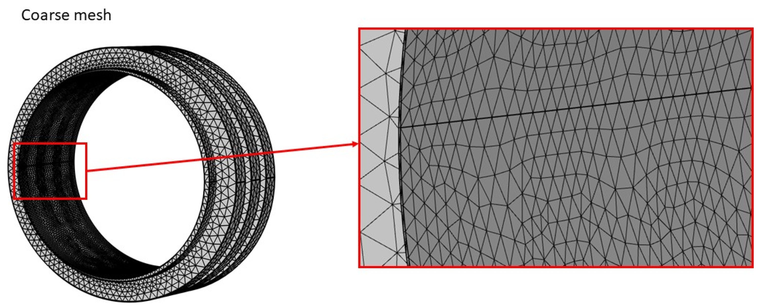
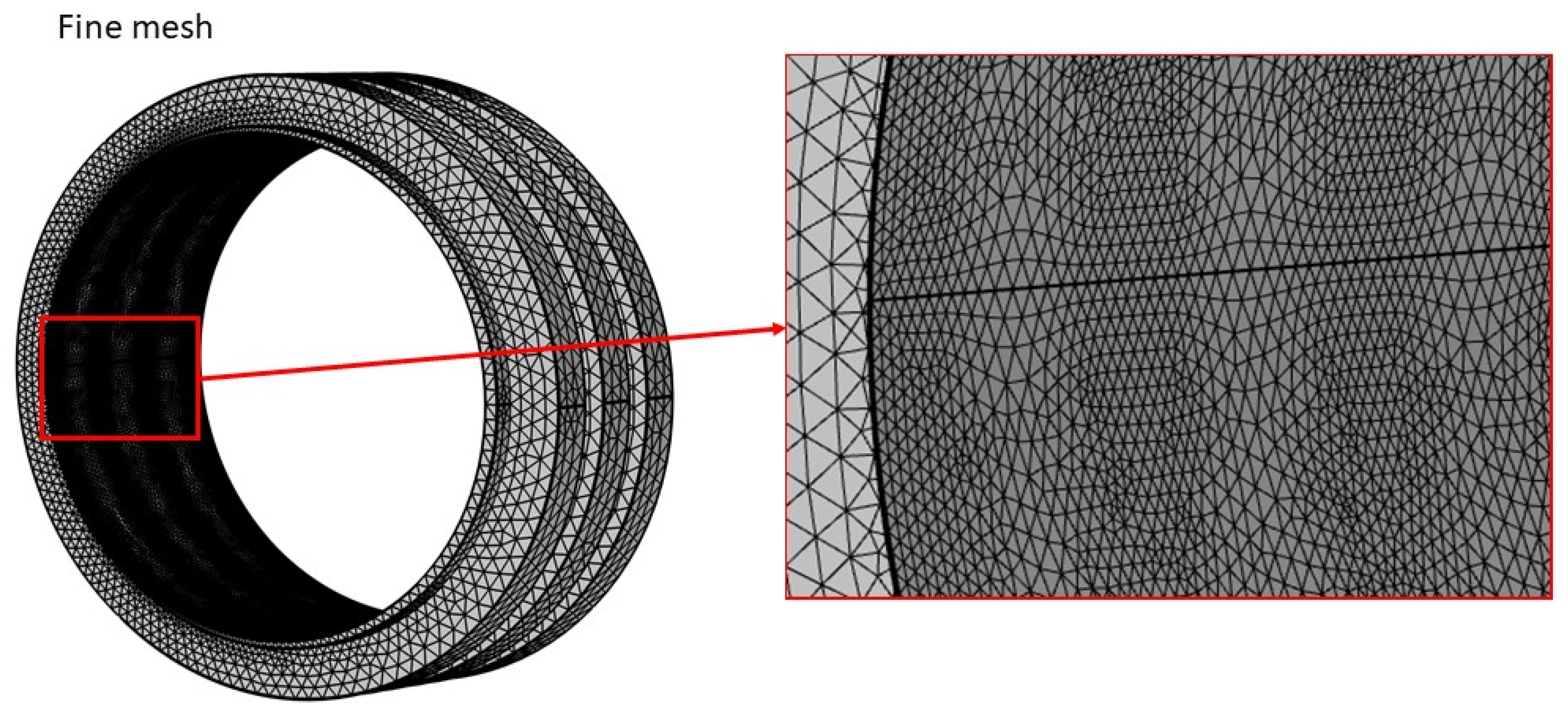
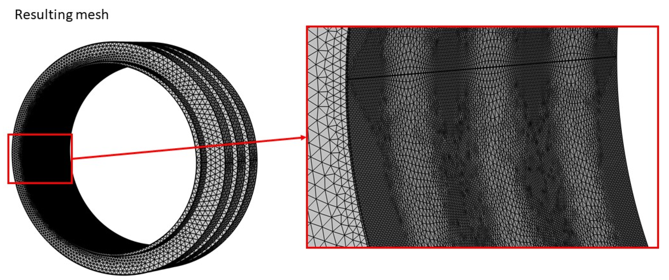
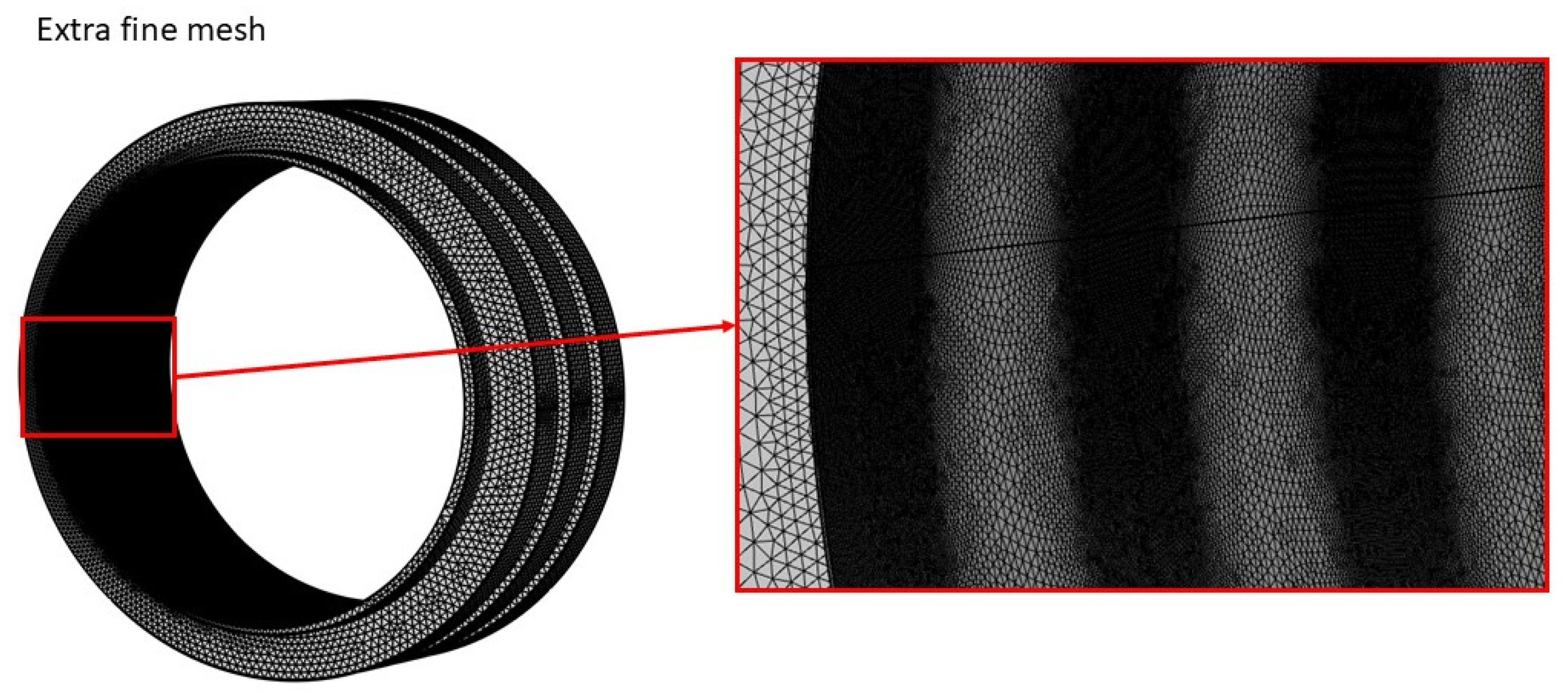
The computational mesh was constructed using the free tetrahedralization method with refinement in the narrow gap zone and wall layers at the cylinder surfaces (10 layers, stretching factor of 1.2). The minimum mesh element quality, equal to 0.086, was evaluated using the built-in criterion in Comsol—the normalized volume of a tetrahedron relative to that of a regular tetrahedron with the same edge length (orthogonal quality). A value of 0 corresponds to a degenerate element, while a value of 1 corresponds to a regular tetrahedron. The results of the corresponding studies of the mesh independence are given in
Appendix A.
To conduct a comprehensive parametric study of the characteristics of a magnetorheological fluid seal, a parametric sweep was applied over the angular velocity
ω and eccentricity using the solution of the previous step as an initial guess. The stationary problem was solved using the Newton method with an initial step damping of 0.3 and a pseudo-time step (CFL = 5). The convergence criterion for the solution was a relative residual of less than 10
−5. The result of the solution was the pressure distribution in the computational domain.
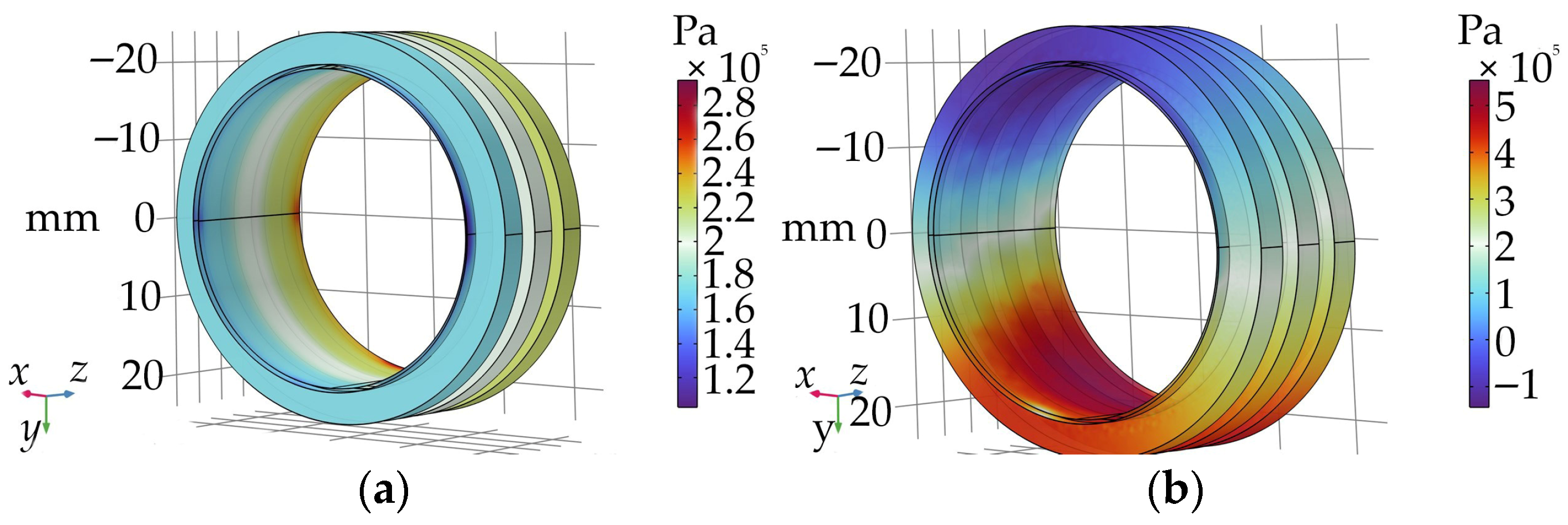
Figure 3 shows examples of pressure distribution for an angular velocity of
ω = 200 rad/s. The rotor eccentricity is
e = 0.3 mm along the
X1 axis (
Y axis).
Figure 3a shows the pressure distribution for
B = 0 T, and
Figure 3b shows that for
B = 0.2 T.
The integral characteristics of the magnetorheological seal included the load capacity arising from the rotor and stator eccentricity, as well as the frictional torque of the fluid layer. The seal’s load capacity was determined by integrating the effective pressure across the stator surface:
The friction torque is determined by integrating the full stress tensor over the stator surface:
where
Ti are components of the total stress tensor.
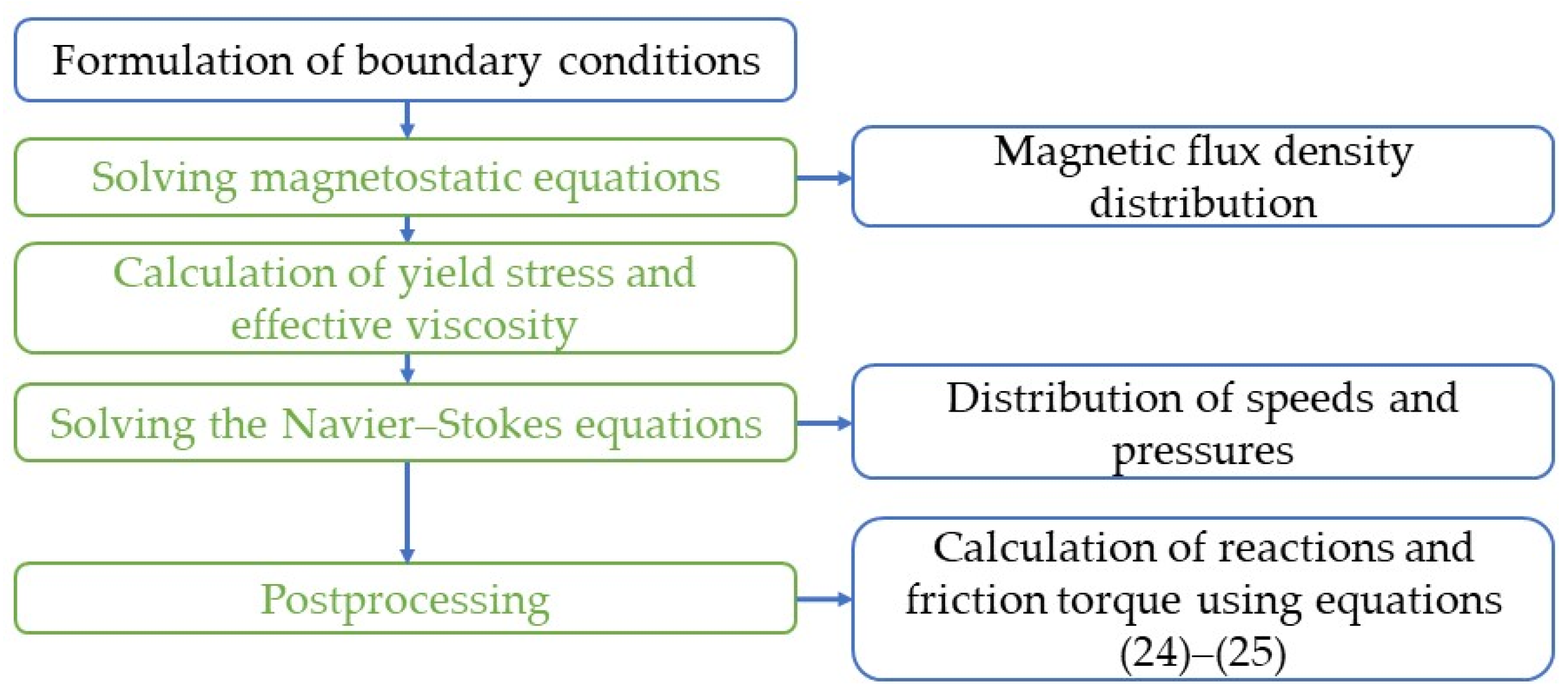
Figure 4 shows the flowchart of this study.
Table 1 presents the variables and constant parameters used in the study.
Due to the absence in the open literature of comprehensive experimental works simultaneously containing data on pressure distribution in an eccentric gap and the friction torque of an MRF seal, verification of the proposed model was carried out in two independent stages using two different sources of experimental data.
The results of the pressure field calculation in the seal gap were compared against the experimental data of [
32]. The seal assembly design described in that work is substantially similar to the geometry considered in the present study. In both cases, an annular sealing gap is implemented with a permanent magnet as the field source and MRF as the sealing medium. This geometric similarity ensures the validity of the comparison and accounts for the level of agreement achieved: the maximum deviation of the calculated pressure values from the experimental ones did not exceed 9.5%.
The results of the friction torque
M calculation were compared against the experimental data of [
33], which reports measured dependencies of friction torque on magnetic flux density
B0 in the range of 50–300 mT under rotational shear of MRF. It should be emphasized that the geometry of the experimental device in that work (an annular chamber with a piston generating both pressure and rotation simultaneously) differs substantially from the configuration used in the present study. To ensure a valid comparison, the proposed mathematical model was adapted to the geometric configuration from the work of Spaggiari and Dragoni: the calculation was performed on an analogous computational domain with the same boundary conditions and rheological parameters of MRF 140-CG. The resulting deviation of the calculated friction torque values from the experimental ones was 13.5%, which is an acceptable outcome given the substantial difference in geometries and confirms the general applicability of the proposed model to problems of this class.
Thus, the verification procedure performed demonstrates that the proposed mathematical model satisfactorily reproduces both the characteristics of the MRF seal (pressure field) and its tribological characteristics (friction torque) over a wide range of magnetic flux densities, thereby confirming its suitability for the parametric study.
3. Results and Discussion
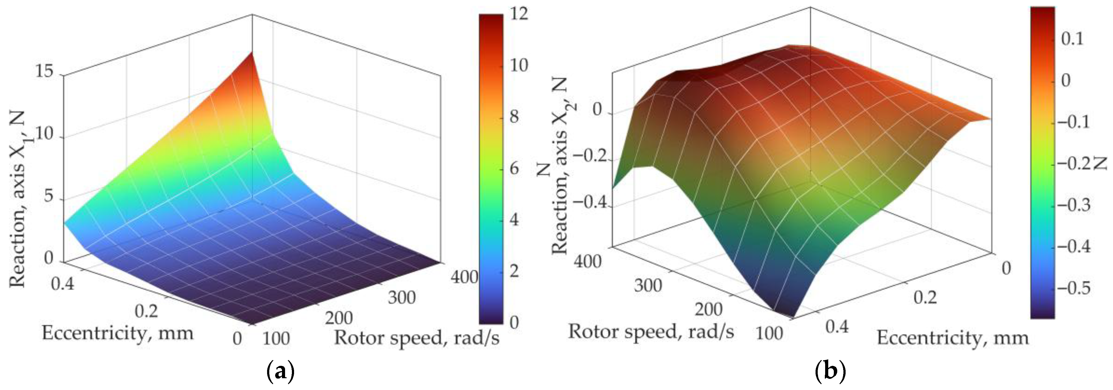
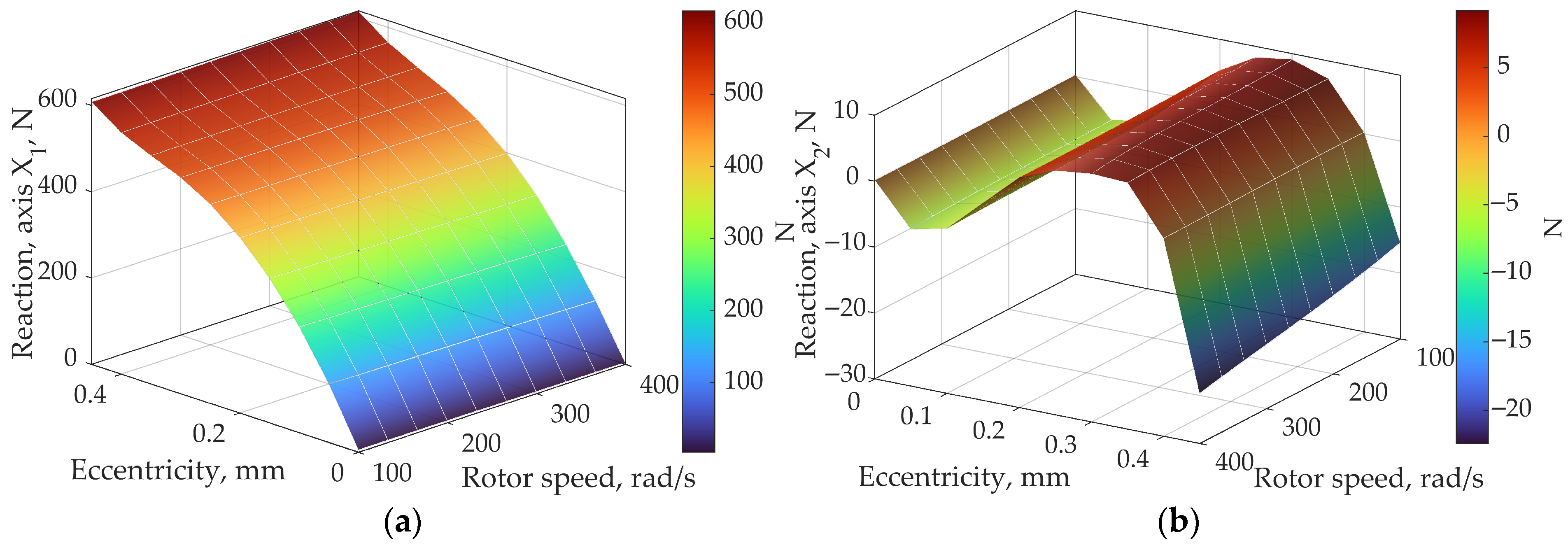
The response surface characterizing the seal reaction force component
F1 along axis
X1 is shown in
Figure 5a, whereas the response surface characterizing the seal reaction force component
F2 along axis
X2 is shown in
Figure 5b. Forces
F1 and
F2 are functions of the linear eccentricity
e and rotor angular velocity
ω in the absence of a magnetic field (
B0 = 0). The results correspond to the purely hydrodynamic flow regime of a Newtonian fluid. The component
F1 (the direct seal reaction force) is the dominant one due to the displacement of the inner cylinder along axis
X1, reaching a maximum value of 12 N at
e = 0.45 mm and
ω = 400 rad/s, and exhibiting a nonlinear increase with eccentricity, consistent with hydrodynamic wedge theory in the classical Sommerfeld framework. The dependence of
F1 on angular velocity is approximately linear, in accordance with the Reynolds equation. At zero eccentricity, the reaction force
F1 vanishes, which is physically associated with the absence of a hydrodynamic wedge in the concentric configuration. The second reaction component
F2 (the cross-coupled seal reaction force) is significantly smaller in magnitude (up to 0.6 N) and takes predominantly negative values, growing in absolute magnitude with both parameters. The negative sign of
F2 indicates the destabilizing nature of the cross-coupled reaction perpendicular to the direction of displacement, which is a characteristic feature of fluid film seals and journal bearings.
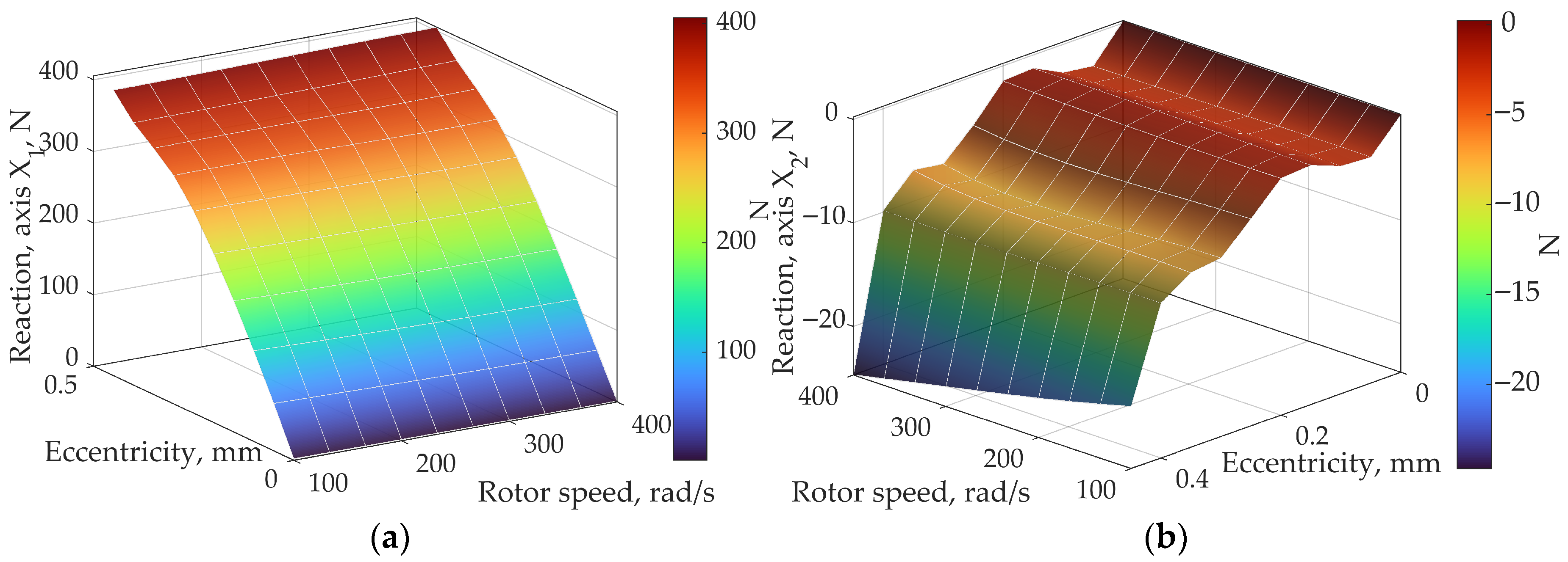
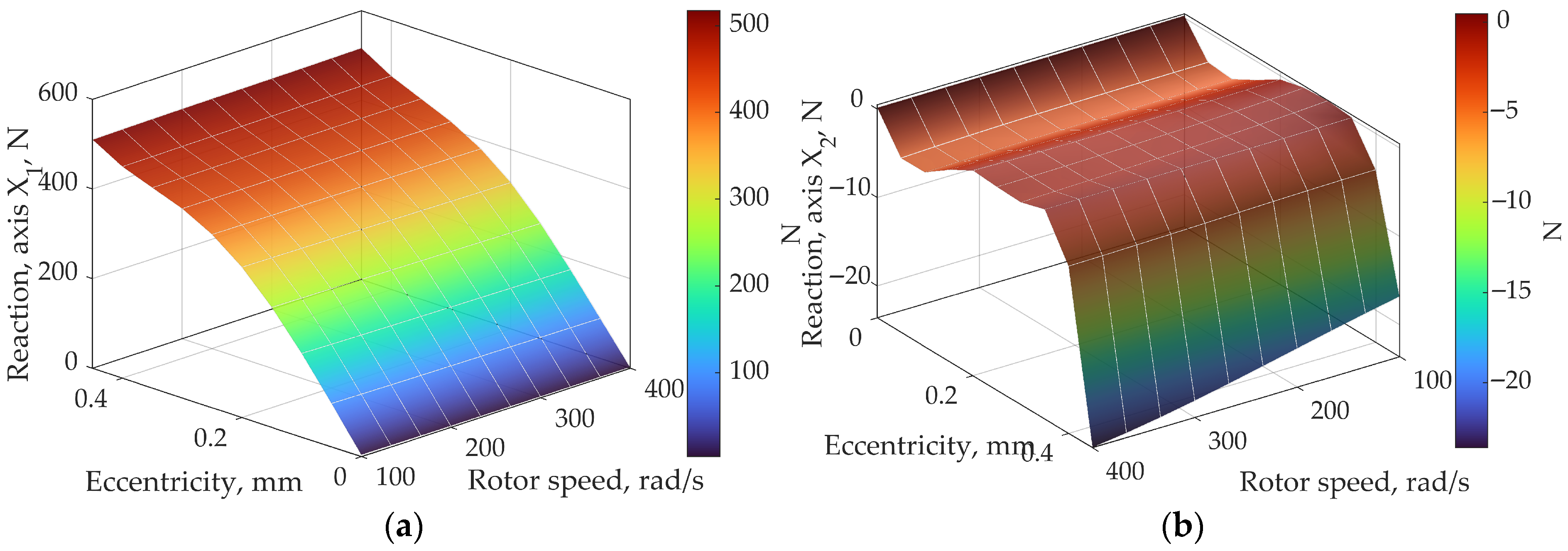
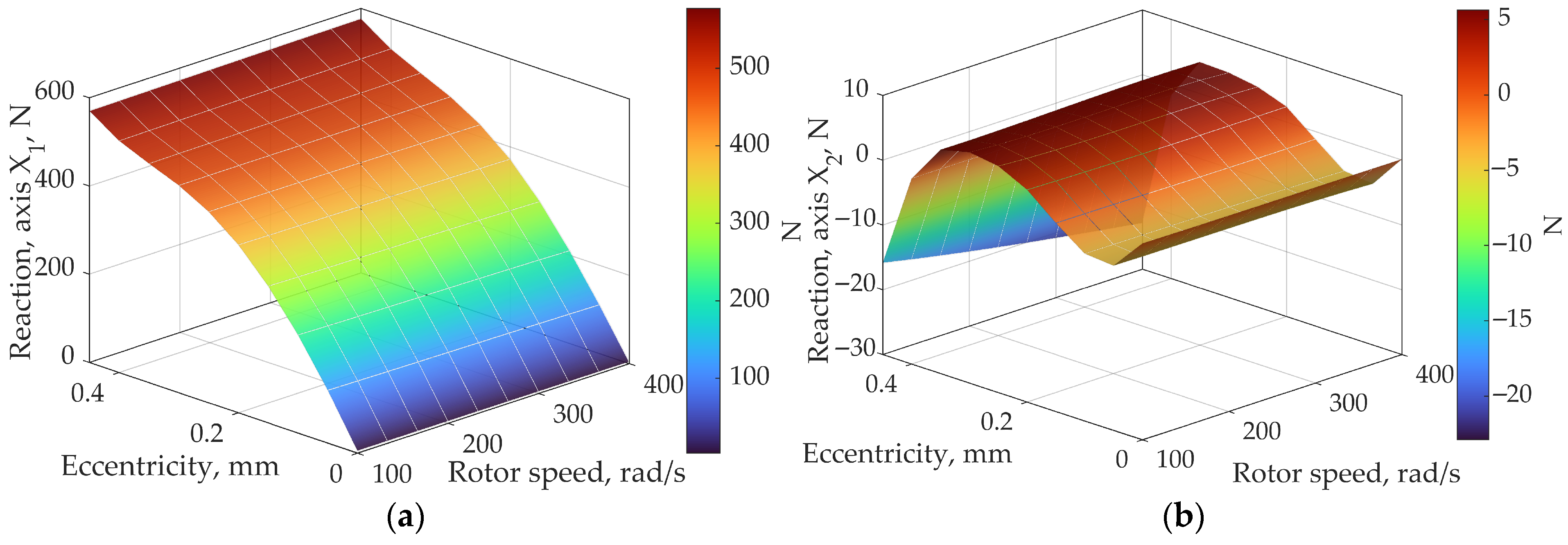
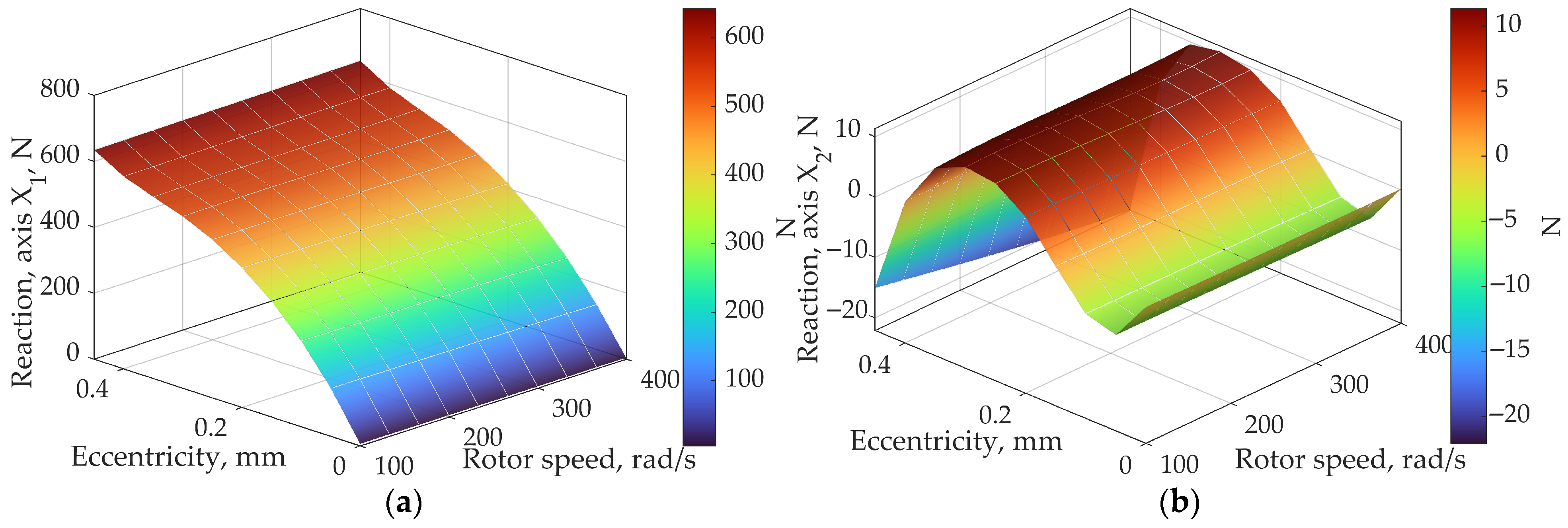
Figure 6,
Figure 7,
Figure 8,
Figure 9 and
Figure 10 show the response surfaces of the seal reaction force components
F1 and
F2 as functions of eccentricity
e and rotor angular velocity
ω for magnetic flux densities
B0 = 0.1, 0.2, 0.3, 0.4, and 0.5 T.
Figure 6a,
Figure 7a,
Figure 8a,
Figure 9a and
Figure 10a represent horizontal reaction
F1 along axis
X1 and
Figure 6b,
Figure 7b,
Figure 8b,
Figure 9b and
Figure 10b represent vertical reaction
F2 along axis
X2 for each configuration of magnetic flux density
B0. Application of a magnetic field even at the minimum value of
B0 = 0.1 T leads to a fundamental change in the characteristics of the
F1 surfaces. The reaction force increases to 450 N, which is more than an order of magnitude above the hydrodynamic case (
B0 = 0); at the same time, its dependence on eccentricity becomes more gradual. This phenomenon is explained by the dominance of the Bingham yield stress
τy over viscous stresses at Bingham numbers
Bn ≫ 1. The fluid acquires quasi-solid properties in the narrow-gap region regardless of its geometry, so that the load capacity is governed primarily by the field-dependent
τy(
B) rather than by the curvature of the pressure wedge. As the flux density increases from 0.2 to 0.5 T, the growth of
F1 decelerates noticeably and its maximum stabilizes in the range of 600–700 N, directly reflecting the saturation of the yield stress according to the hyperbolic approximation (Equation (20)). The dependence of
F1 on angular velocity retains an approximately linear characteristic at all values of
B0; however, the slope of the surface along the
ω-axis decreases with increasing field, as the contribution of the hydrodynamic wedge to the total reaction becomes relatively less significant compared to the magnetorheological component. The behavior of the second component
F2 undergoes a qualitative transformation; at
B0 = 0.1 T the
F2 surface remains predominantly negative with monotonically increasing magnitude; starting from
B0 = 0.3 T, a change in sign is observed in the low-velocity region, leading to an inflection on the response surface. This indicates the presence of two contributing mechanisms: a hydrodynamic one, which generates a force opposing the direction of rotation, and a magnetorheological one, which introduces an additional normal reaction in the plane of displacement. At
B0 = 0.4–0.5 T, the magnitude of
F2 reaches 25–30 N, corresponding to approximately 4% of
F1. However, the systematic growth of the ratio |
F2|/
F1 with increasing flux density indicates an intensification of cross-coupling and a corresponding reduction in the rotordynamic stability of the seal at elevated field levels.
It should be noted that the computed horizontal reaction F2 is strongly dependent on mesh quality. This influence is particularly pronounced at high eccentricities. When per-forming rotordynamic stability analyses, mesh quality must be carefully considered and numerical outliers should be examined.
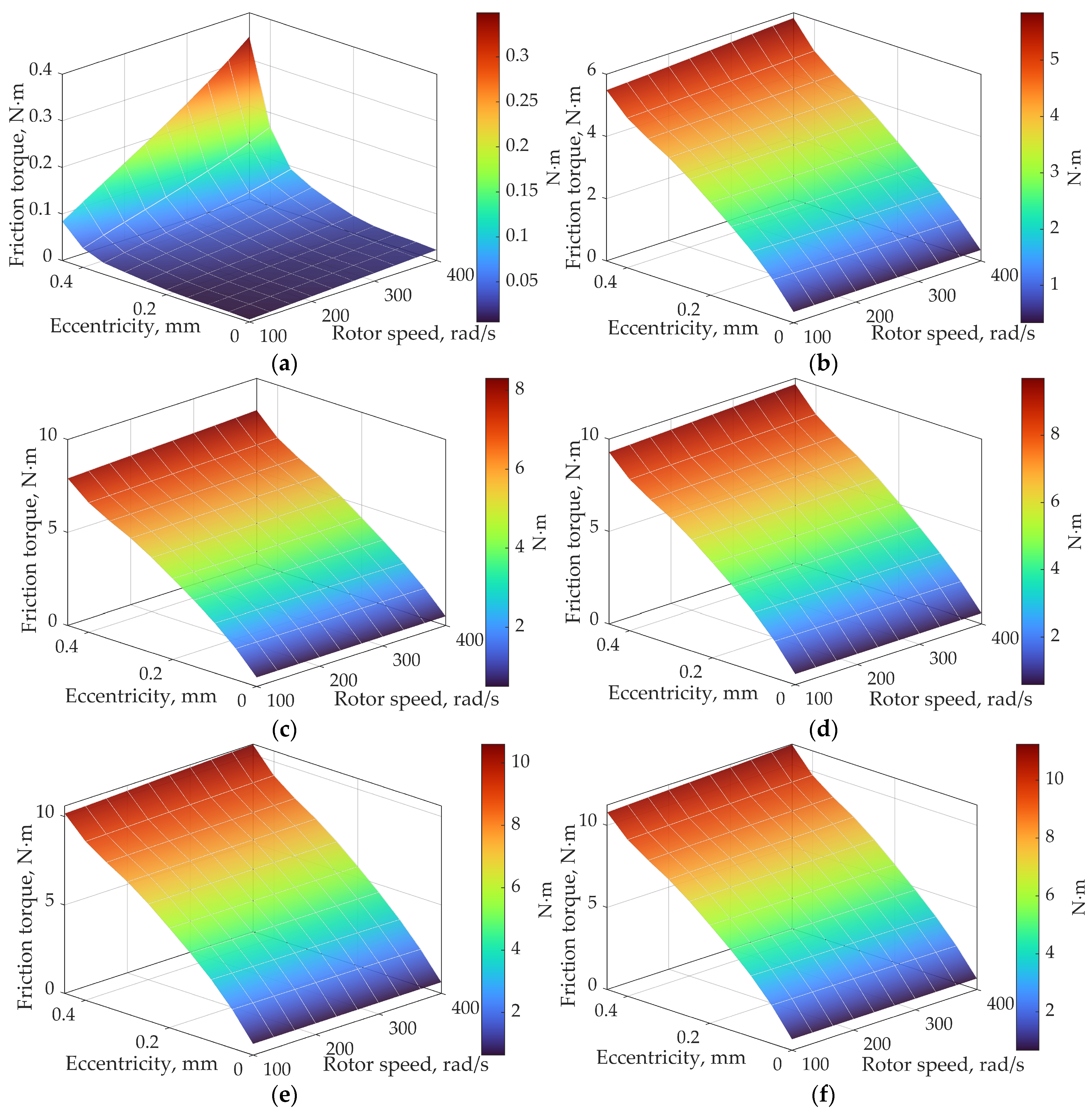
Figure 11 shows the friction torque surfaces
M as functions of eccentricity
e and rotor angular velocity
ω for magnetic flux densities
B0 = 0.1, 0.2, 0.3, 0.4, and 0.5 T. Comparison with the hydrodynamic baseline (
B0 = 0,
Mmax = 0.35 N·m) reveals a fundamental change in the shape of the response surface. At
B0 = 0.1 T, the friction torque increases approximately 17-fold (to 6 N·m), which is attributable to the emergence of the Bingham yield stress contribution to the tangential stresses on the rotor surface. Unlike the purely viscous case, where wall shear stresses are concentrated primarily in the narrow-gap region, the yield stress
τy acts essentially uniformly over the entire lateral surface of the rotor, fundamentally redistributing the stress load. This gives a qualitative transformation of the
M(
e, ω) response surface morphology. Whereas at
B0 = 0 a pronounced peak in friction torque is observed at maximum eccentricity and rotor speed, at
B0 > 0 the surface becomes markedly flatter along the eccentricity axis, and the friction torque becomes nearly independent of the degree of cylinder misalignment. This behavior physically implies that at high Bingham numbers (
Bn ≫ 1), the formation of a plug zone in the narrow-gap region redistributes the tangential stresses such that their integrated contribution to the friction torque is governed primarily by the field-dependent
τy(
B0) rather than by the local gap geometry
h(
θ). The dependence of
M on angular velocity retains an approximately linear characteristic at all values of
B0 with a nearly constant surface slope, consistent with the Papanastasiou model. At a fixed field, the effective viscosity
µeff is dominated by the component
τy/
, where
~
ω, so that the product
μeff ∙
ω ~
τy = const, ensuring a linear growth of
M(
ω). As the flux density increases from 0.2 to 0.5 T, the rate of torque growth decelerates markedly. The maximum values of
M increase from 10 N·m (
B0 = 0.2 T) to 12 N·m (
B0 = 0.5 T), directly reflecting the saturation of the yield stress
τy according to the hyperbolic model (Equation (20)): at
B ≫ Bsat, further increases in flux density yield no significant growth in wall shear stress on the rotor surface.
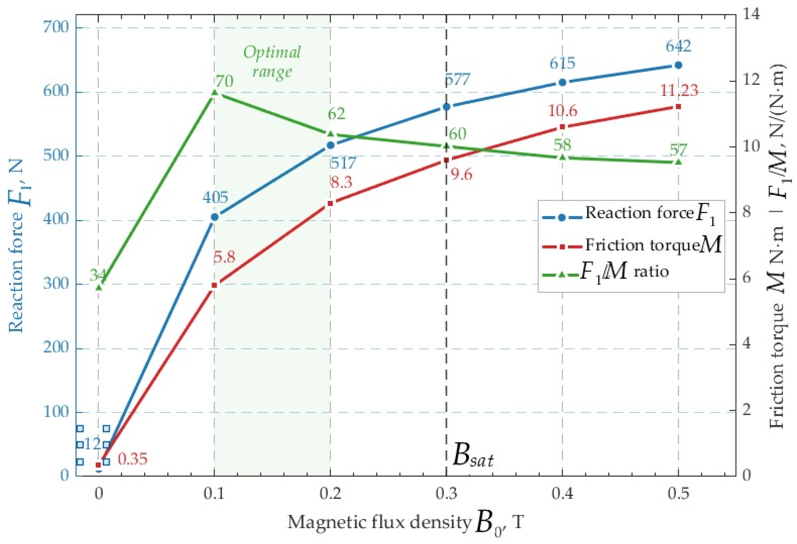
Figure 12 shows the summarized dependencies of the seal reaction force
F1 and the friction torque
M on the magnetic induction
B0, obtained at a fixed angular velocity
ω = 400 rad/s and eccentricity
e = 0.45 mm. The plot clearly demonstrates two distinct regimes of system behavior, separated by a vertical dashed line at the saturation area
Bsat = 0.3 T.
In the range B0 = 0–0.3 T, both curves exhibit pronounced nonlinear growth. The reaction force F1 increases from 12 N to 577 N (a 48-fold increase), whereas the friction torque M increases from 0.35 N·m to 9.6 N·m (a 27-fold increase). The faster growth of F1 compared to M in this range is explained by the different scaling of the two components with the Bingham number Bn.
In the saturation region (B0 > 0.3 T), the characteristic of the curves changes only slightly, as both curves transition to a markedly subdued growth rate. Specifically, the increment in F1 from 0.3 to 0.5 T is only 65 N (11%), while the increment in M is 1.63 N·m (17%), which directly reflects the yield stress τy reaching a plateau according to the hyperbolic saturation model (Equation (20)).
In the saturation region, the friction torque M increases relatively faster than F1, indicating a reduction in the energy efficiency of the sealing process at excessively high magnetic field levels. The range B0 = 0.1–0.2 T can be identified as optimal in terms of maximizing load-carrying capacity while minimizing additional friction losses.
The observed ratio of load capacity F1 to friction torque M across the range B0 = 0.1–0.5 T indicates that the magnetic field augments the reaction force F1 at a faster rate than the friction torque M, which is energetically favorable from a seal performance standpoint, as the load capacity-to-friction torque ratio F1/M increases from 34 N/(N·m) at B0 = 0 T to 70 N/(N·m) at B0 = 0.1 T, identifying the existence of an optimal field level at which the gain in load capacity is maximized for a moderate increase in drive power consumption.
The results obtained confirm that magnetic field control can be effectively utilized to regulate the performance characteristics of MRF seals over a wide range; however, a practically significant improvement in performance is achieved within a relatively narrow range of magnetic flux density (0–0.3 T), whereas a further increase in the field entails unjustifiable energy expenditure associated with generating the magnetic flux.