1. Introduction
To date, many machine elements, such as bearings, gears and seals, have been designed as passive devices. The geometry of these elements and the properties of the lubricant are not generally controlled under operational changes to the load, lubricant entrainment speed, or operating temperature. However, it is often the case that the geometry of the lubricated clearance space of these devices “self-adjusts” to an equilibrium adapting to different operating conditions. Despite these changes, the operating state of these components will always be predefined for given operating conditions. The design and principle of operation of such passive devices creates a fundamental issue. If improvements are to be made in the performance of a machine element, they tend to be restricted to the benefits that can be realised through small, incremental and stepwise improvements. These may involve more wear-resistant materials, lighter or stronger components, lower viscosity lubricants, surface topography changes, etc. The effect of incremental improvements in materials over several decades leading to reductions in the mass of rolling element bearings and hydraulic motors which perform roughly the same duty have been reported by Glavatskih and Högland [
1]. However, it is evident that such improvements tend to give smaller returns over time, so such optimisation has a natural limit. Additionally, any secondary parameter, such as power loss (which depends on friction), will also always be the same. Controllable or active interfaces, generally referred to as “tribotronic devices” [
1] offer a transformative solution to this situation, allowing parameters such as friction to be reduced (or controlled) by levels which would otherwise not be possible. Tribotronic elements employ a feedback-control system to change the operating state by using a system of sensors and actuators. This new paradigm allows additional design approaches to be used to enhance the basic performance of a machine element as well as permitting a wide range of different “optimisation goals” to be established for any particular operating condition.
Optimisation goals can take many forms, including minimal wear, minimal frictional losses, specific lubricating-film thickness, contact stiffness and damping, operating temperature, etc. Additionally, using tribotronics, optimisation goals for components can be changed during service and can be bespoke for specific components. In principle, tribotronic components offer many potential benefits over passive systems, including improved function, increased maintainability, extended life (lower wear), reduced friction (lower power loss), as well as real-time duty, information about the lifetime duty, and the chance to estimate the remaining useful life of the system. As such, they integrate extremely well with the principles of Industry 4.0 [
2].
An extensive review [
2] highlights many of the numerous studies and commercial applications in the field of tribotronics in recent years. The purpose of the current paper is to focus specifically on the management of power loss. It presents case studies of two components, tilting pad bearings and piston-ring seals, to demonstrate how widely used conventional mechanical components can offer significantly improved frictional characteristics when they are implemented in tribotronic forms. Reduced frictional losses lead to many advantages, including lower operational costs and lowered environmental impact through reduced emissions and reduced energy consumption.
2. Tribotronic Systems
The reliable operation of machine elements involving sliding and rolling contact generally depends on the design of their interface surfaces and their lubrication. The development of a range of technologies including miniaturised sensors, small actuators, embedded computing, wireless communication, additive manufacturing, smart materials, coatings, etc. has recently made active management of contact interfaces a realistic proposition. At first, it may appear a distant and unrealistic proposition that interface friction can be controlled; however, there are already many practical systems of this type in common use. These include anti-lock braking systems (ABSs) [
3], traction control systems [
3], and clutch pressure control arrangements in automatic transmissions [
4]. In addition, magnetic bearings (widely used in vacuum systems) [
5] and some hydrostatic bearings [
6] are used, commercially, foruse active control of shaft position.
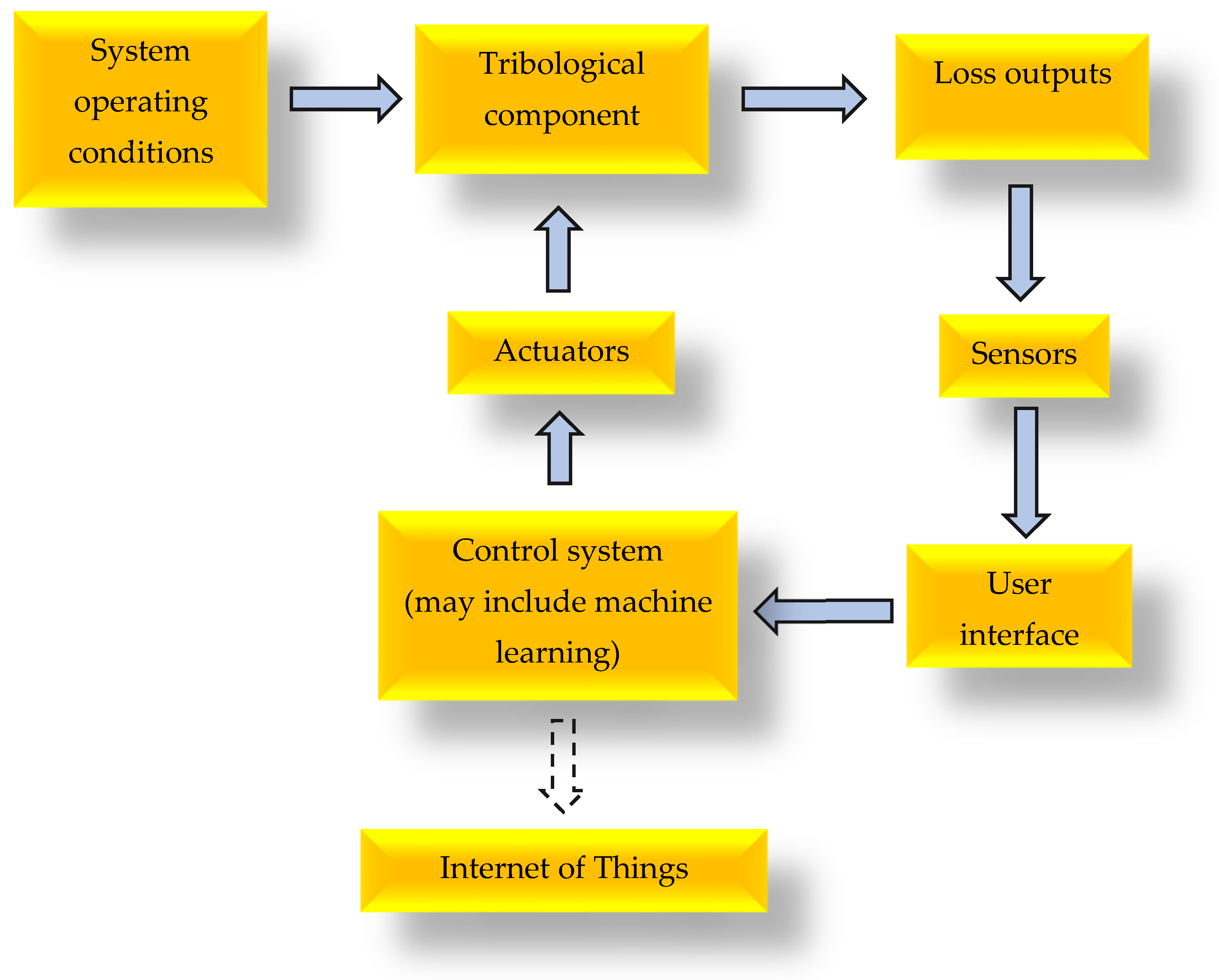
Figure 1 presents a schematic layout of a tribotronic system. It shows a conventional tribological component which has been adapted by the inclusion of sensing, a control system and an actuator. This arrangement allows it to respond to changes by making adjustments to its operating state to meet a specific demand.
Unlike conventional control methodologies, in tribotronics the state variables are referred to as “loss outputs”. These are parameters which tend to be specific to tribology such as friction/traction coefficients, lubricating-film thickness, wear rates, etc. Any control system requires an appreciation of a number of interacting factors, such as lubricant flow rate, temperature/pressure viscosity relationships for the lubricant, and parameters related to heat flow in the components themselves. To achieve effective control, an understanding of the temporal response of the system is also required. For example, even though contact film thicknesses may change, more or less, instantaneously in response to changes in applied load, a delay of some minutes will be required for thermal equilibrium to re-establish. Compromises are also required during control, so while lower film thickness may give rise to reduced power loss, high wear rates in interface components may also result. A multi-factor optimisation approach is thus required.
Other contrasts with conventional control systems are also evident in tribotronics. The time-based condition of the components and lubricant in the interface alters with time. Wear of components will change their dimensions and surface topography, and the lubricant will change its viscosity as well as its physical and chemical composition. For example, the evaporation of lighter molecular components will influence viscosity.and war debris/combustion products may accumulate in the lubricant changing its wear characteristics.Chemical properties such as acidity (pH) will be influenced by contaminants affecting corrosion. The changes in these properties can also be controlled or compensated for by adaptive control using tribotronics, and this offers exciting opportunities in the reduction of direct maintenance.
In summary, there are at least five main reasons for implementing tribotronic control; they are to:
Increase functionality—improving the tribological properties of a system;
Extend maintenance intervals—some changes can be addressed by autonomous control;
Incorporate flexibility—changes in optimisation goals can be implemented during operation with different objectives prioritised at different times. For example, minimising wear may be used instead of minimising friction to extend lifetime;
Develop a “full-life” record of duty and performance—to facilitate better understanding of the tribological behaviour of a component;
Facilitate remote software up-dates—to address challenges or to incorporate improvements.
This paper focusses on the application of tribotronics to optimise (reduce) friction and presents case studies describing the management of lubrication in two components:
In both cases it is clearly demonstrated that tribotronic control can deliver significant improvements in the operation of these components over passive designs.
3. Case Study One: Active Control of Tilting-Pad Thrust Bearings
3.1. Conventional Tilting-Pad Thrust Bearings: Principle of Operation
Tilting-pad thrust bearings (TPTBs) are a form of hydrodynamic bearing often used to support the axial thrust of rotating shafts in high-speed, high-load applications such as hydroelectric generators, gas turbines, and marine propulsion systems. TPTBs consist of several independent sector-shaped pads which tilt on a pivot to form a convergent wedge between the pad surfaces and a rotating collar on the shaft. The lubricating fluid, typically a mineral oil, is entrained by the rotating collar into this convergent wedge, generating a pressurised fluid film capable of supporting substantial loads. Intense viscous shearing in the lubricating film gives rise to substantial heat generation and power consumption, which requires careful management to ensure component reliability and machine efficiency.
Dixon and Humble report that the TPTB design was patented independently in the early 20th century by both Michell and Kingsbury [
7]. TPTBs generally operate as passive devices. The pads are free to tilt to an equilibrium position which establishes a balance of the hydrodynamic moments around the pad pivot. The advantage of TPTBs, compared with fixed inclined bearings, is that the inlet-to-outlet film-thickness ratio (convergence ratio) is a function of pivot position and remains largely independent of operating conditions, provided thermal effects and side leakage are negligible [
8]. Steady-state characteristics, including load-carrying capacity and power loss, are strongly influenced by the convergence ratio; therefore, appropriate selection of pivot position during design is essential for optimising bearing performance.
Many pad designs employ pivots located around 60–65% of the distance between the inlet and the outlet, with the intention of maximising the bearing load-carrying capacity. However, designs with increased offsets (e.g., 70–80%), have been shown to reduce film temperatures, and power consumption, with beneficial effect on machine efficiency [
9,
10]. Alternatively, bidirectional applications utilise centre pivot pads to allow reverse rotation. The functional performance of centre pivot pads is largely dependent on thermo-elastic distortions and convexity of the pad, making it exceedingly difficult to optimise the film profile compared to their offset counterparts [
11]. As a result, centre pivot designs often operate at higher operating temperatures with increased power consumption and lower load-carrying capacity [
12].
These inherent trade-offs make it almost impossible to optimise both energy efficiency and reliability in passive designs. Consequently, active tribological approaches are now being explored to overcome such limitations. The following section presents a case study of a tribotronic tilting-pad thrust bearing (TTPTB) developed to optimise power consumption.
3.2. Tribotronic Thrust-Pad Bearings
Active control (tribotronic) methods in hydrodynamic bearings can be broadly divided into two categories:
Lubrication control, which seeks to influence performance by adjusting rheological properties or by modifying flow rate and pressure;
Geometric control, which focusses on actively controlling the shape of the oil film. This typically require actuators, such as hydraulic cylinders, piezoelectric stacks, mechanical adjusters, and embedded deformation control elements.
Each method has its own advantages and disadvantages in terms of control authority, cost, complexity, and reliability, and each exhibits differing levels of technological maturity. Active geometric methods have been widely studied in radial tilting-pad bearings due to their ability to influence rotor dynamic characteristics and mitigate harmful instabilities [
13,
14,
15]. However, such methods are less developed in thrust bearings because the control objectives generally differ significantly.There is more focus on power loss and load-carrying capacity in TPTB with much less interest in control of stiffness and damping. In TPTBs. tThe dominant loss mechanisms are viscous shearing, oil churning and, under certain conditions, wear and friction during start-up and shutdown. Among these, viscous shearing is the predominant mechanism accounting for the largest proportion of losses [
16]. Viscous shearing depends heavily on the viscosity of the lubricant but also on the shape and thickness of the oil film.
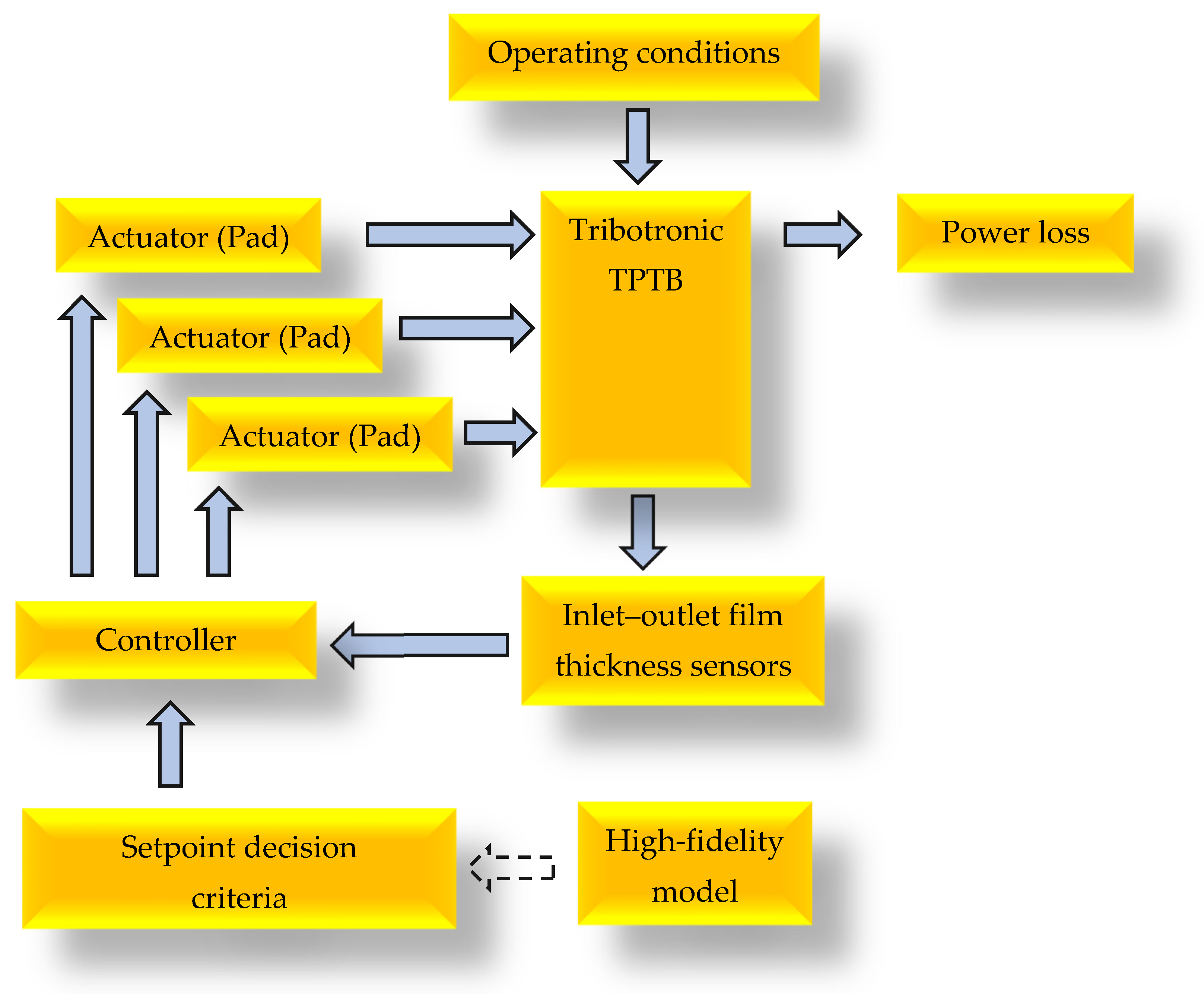
The authors have developed a TTPTB with an externally controllable pad tilt. It operates by actively regulating the convergence ratio, thereby modifying performance characteristics on-line. A thermo-hydrodynamic model has also been developed in COMSOL Multiphysics V5 to analyse the performance of this bearing. The model considered the effect of force actuation through a lever arm that applied a controlled torque to the pads, allowing tilt positions outside the passive equilibrium state to be achieved. A schematic diagram of the tribotronic system is presented in
Figure 2.
Mechanical micro-adjusters were mounted to the rear of the bearing pads through rod ends and lever arms. Each pad was also instrumented with two capacitance-based oil-film-thickness transducers (OFTs), positioned at the inlet and outlet, allowing measurement of the convergence ratio for feedback control. In the set of experiments, each pad was incrementally tilted until a numerically determined, optimal convergence ratio for power loss was achieved. The test apparatus also facilitated direct frictional torque to be measured, providing accurate measurement of power consumption. Data from the experimental apparatus was compared with that obtained from the COMSOL-based model.
3.3. Modelling: Overview of the COMSOL Model
The thrust bearing investigated in this study consisted of three pads from a nominal six-pad configuration (0.5 complement). In the model, the bearing was assumed to be aligned with the collar, and a single controllable-pad approach was employed. The overall bearing performance characteristics were extrapolated based on the total number of pads. Both the collar and pad were modelled as smooth and rigid, and a fully flooded lubrication condition was assumed. The pad was modelled with a line pivot, and a force actuator was used to apply a controlled force to the tilting-pad. In the model, the collar rotated with a constant angular velocity under a static load. The local film thickness at any point on the pad was defined by geometric considerations, and a force balance equation was used to model changes in film height and pitch angle caused by the operating conditions and actuation force.
The COMSOL solver implemented a Newton–Raphson method scripting tool for the root-finding equilibrium problem to solve for the state variables defined in the film function, allowing the hydrodynamic forces to be determined by integration of the pressure distribution across the pad surface. Under the assumption that the interface was lubricated with a viscous, incompressible, Newtonian fluid, the pressure distribution was obtained by solution of the 2D Reynold’s equation using COMSOL.
The lubricant flow was assumed to be laminar and fully formed between the thrust-pad and collar and cavitation was neglected as the collar and pad were assumed to be rigid and smooth with no diverging regions. The no-slip boundary condition was imposed at the collar and pad surfaces. Pressure at the edges of the fluid domain was set to be ambient.
A discretised form of the energy equation was employed within COMSOL to model the heat transfer in the oil film, and a thermally thin approximation was used, where heat transfer occurred in the circumferential and radial directions.
Density variation of the lubricant with temperature was assumed to be negligible, with the temperature dependence of viscosity being described by an implementation of the Vogel equation. The fluid viscosity was modelled as spatially varying in the circumferential and radial direction but constant across the film-thickness direction. The oil employed was an ISO VG 46 medium turbine oil.
3.4. Experimental Apparatus
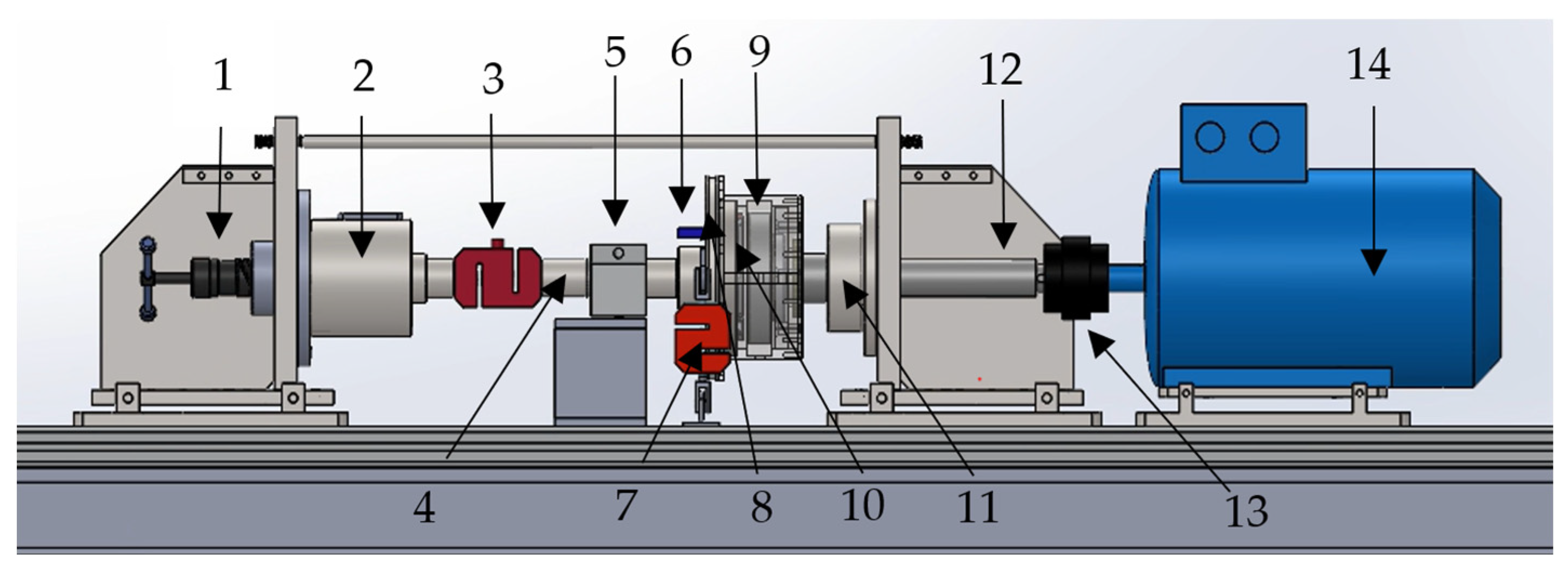
A bespoke test apparatus, illustrated in
Figure 3, was developed to assess the performance of the tilting-pad thrust bearing with controllable pads. The apparatus was arranged in a horizontal, dual-shaft, single-collar, single TPTB configuration. A manual press was used to apply static axial load, which was transmitted through an angular contact ball bearing (ACBB) contained within a precision sliding bore. A 25 kN S-beam load cell (from Tedea-Huntleigh, Worthing, UK)) was used to measure the transmitted force from the press to the tilting-pad thrust bearing (TPTB) which was loaded from the rear against a rotating collar. Force transmitted to the drive side was directed through an additional angular contact ball bearing and loading plate. A 4 kW AC induction motor (from TEC Electric Motors, Hartlebury, UK), with variable speed control, was used to transmit power through a jaw coupling to the drive shaft and collar.
The TPTB and loading shaft was supported by a linear rotary bearing and guide wheels beneath the housing, which provided rotational freedom for torque measurement. The resulting tangential force was measured using a 100 N S-beam load cell (from Force Logic Ltd., London, UK) connected to the housing via a torque arm. The guide wheels were retractable to allow precise setting of concentricity and alignment of the TPTB with the collar.
The housing was pressure-fed through a circulating lubrication system, and the bearing was operated in a fully flooded condition, where cool oil was pumped to the rear of the bearing and excavated from the top of the housing. The flow rate of the circulating system was set to 2.35 L min−1, with a feed pressure of 1.5 bar. The flow rate was chosen to maintain a housing temperature rise below 25 °C, based on predicted power consumption at maximum duty.
The pad actuation mechanism incorporated micro actuators which were connected to the existing pads via a lever arm. The linear displacement was converted to circumferential tilt through spherical rod ends. The actuators were positioned 53° from the line pivot, which provided approximately 0.014° per 10 µm displacement. Capacitance-based oil-film-thickness transducers, situated at the inlet and outlet of the pads, were used to measure the film-thickness ratio.
3.5. Control Arrangements
The tilt of bearing pads can be achieved through a number of approaches, including displacement control or force control. Both of these approaches can be managed by means of a simple control algorithm.
Displacement control (film-thickness feedback): Displacement control is commonly based on lubricating-film-thickness feedback and can be used when direct measurement of lubricant film thickness or pad tilt is available. A set point signal, for example, generated by film thickness transducer measurements at the inlet and outlet, can be used as feedback to drive the actuator and control the convergence ratio. The setpoint, corresponding to an optimisation goal (e.g., minimisation of power loss or maximisation of film thickness) can be determined by either a pad performance model or experimental feedback. Controller gains, for example, in a PID system can be tuned according to the dynamic response of the system to maintain the selected target convergence.
Force control (force feedback): A similar approach (not requiring film-thickness transducers) can be adopted through force control where force actuators are used to generate moments which cause pads to tilt away from their passive position. The actuation force required to generate the pad tilt for a given demand can be determined from model predictions or experimental calibration. The system response depends on several factors, including the rotational stiffness of the pads under hydrodynamic load. Once the response characteristics are determined, a feedback loop can be employed in which the actuator force is measured and adjusted to set the demand by a conventional PID control system.
This paper presents only quasi-static results to illustrate the impact of actuation on steady-state power consumption. The pad tilt was incrementally adjusted in the experimental arrangement through using displacement control across a range of convergence ratios. This allowed accurate power-loss measurements to provide data for comparison with theoretical values from the model.
3.6. Tribotronic Tilting-Pad Thrust Bearings: Performance of Active System
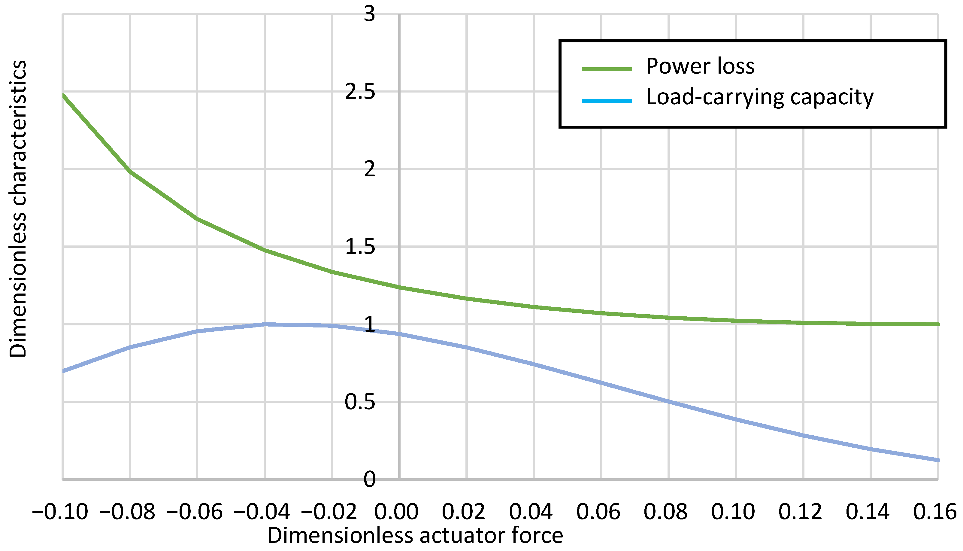
Figure 4 shows the variation in dimensionless power loss and load-carrying capacity as a function of actuation force, both normalized, so that the optimum value is unity. The actuation force is presented in dimensionless form as the ratio of actuator force to the applied load per pad, with tensile forces that increase tilt defined as positive and compressive forces that decrease tilt defined as negative.
It can be seen that power loss and load-carrying capacity depend upon the actuation force due to a controlled change in convergence ratio. In the case of zero actuation force, the pads operate at their passive equilibrium position, which is dependent on the pivot location. The passive position is close to the numerically determined optimum for load-carrying capacity, requiring only a slight compressive force of 3% of the applied load per pad. A tensile force of approximately 15% of the applied load per pad is required to operate at optimal power consumption; this, however, corresponds to a significant decrease in load-carrying capacity.
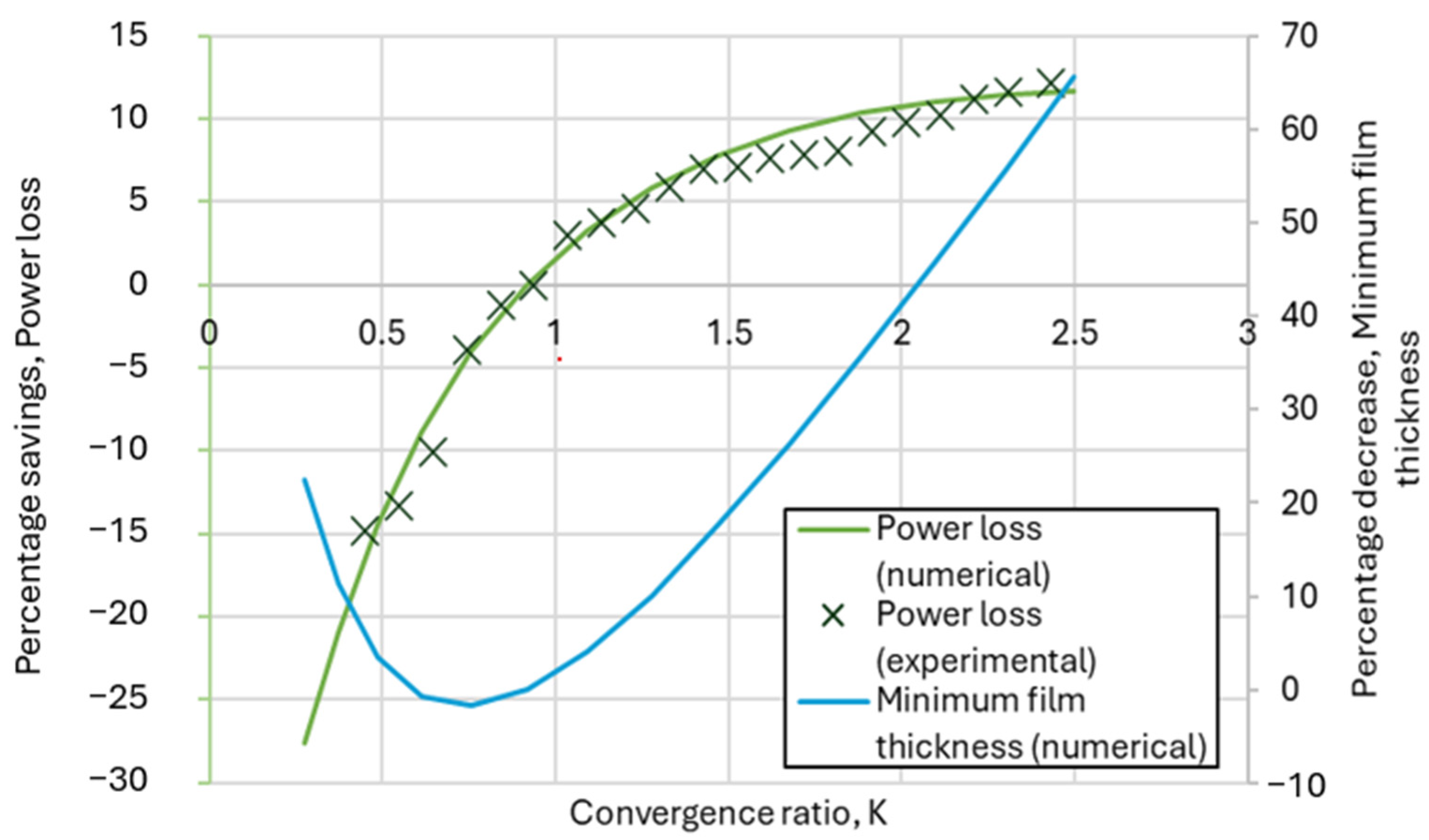
Figure 5 presents a comparison of percentage savings in power loss achieved by adjusting the convergence ratio K of the pads through actuation, where K = ((inlet film thickness/outlet film thickness) − 1). The predictions of the model agree well with the measured results at the tested operating duty (1 MPa, 3000 rpm), and it is apparent that convergence ratios greater than about 0.9 can reduce power loss. The maximum saving in power consumption is shown to occur at a convergence ratio close to 2.5, resulting in a 12% decrease in power consumption for the tested case. Whilst these levels of savings can be achieved,
Figure 5 also shows that minimum film thickness decreases by around 60% risking inadequate lubricating film thickness.
3.7. Tribotronic Tilting-Pad Thrust Bearings: Discussion
Figure 5 highlights a trade-off between efficiency and reliability within TTPTBs. Although actuation can substantially reduce frictional losses, excessive convergence compromises minimum film thickness and care must be taken to ensure that surface contact does not occur. The results therefore underline the potential of using feedback-controlled actuation, where pad tilt is dynamically adjusted using real-time film-thickness monitoring, and balancing the compromise of reduced power loss against reduced safety margins in film thickness to ensure safe, yet efficient operation across varying operating conditions.
Likely candidate bearings for implementation are larger systems such as those used in hydroelectric generators, where the potential energy savings are most significant, or systems operating with thicker lubricant films, which have greater safety margins. In addition, bidirectional systems that typically exhibit inferior performance may also benefit, as the ability to optimise the wedge geometry in both rotational directions could enhance both efficiency and reliability. This has relevance to applications such as large pump-storage units, where sustained bidirectional operation is required.
There are a number of specific areas of possible challenges and improvements in the development of tilting-pad bearings. Some of these areas are discussed below.
3.7.1. Development of Reliable Tribotronic Bearing Systems
Optimising both reliability and efficiency in a single design is challenging, with reliability typically being the primary focus. Development of TTPTBs must therefore demonstrate that efficiency gains can be achieved without compromising reliability. This includes ensuring that the pursuit of optimal states, including lowest power loss, does not result in lubricating-film-thickness values which lead to instability, or lubricating films which are so thin that contact with the runner may occur and cause damage. “Failsafe” and redundant mechanisms will be essential to allow the system or bearing to revert to passive operation in the event of control failure. Active magnetic bearings are an example of this; they often incorporate backup rolling element bearings and redundant sensors to maintain safe operation. Similarly, actuators in TTPTBs may be designed with decoupling elements to ensure that pads can safely return to their passive operation if active control is lost. Such design approaches could be to use non-contact actuators, such as electromagnets, or hydraulic actuators with bypass systems, in addition to actuator redundancy.
Dynamic conditions also require consideration. When large dynamic forces cause significant film-thickness displacements, particularly at high frequencies, the actuator must respond faster than the loading frequency, and the control gains must be accurately tuned to ensure stability and accurate setpoint tracking.
3.7.2. Compact Actuators in Bearings
TPTBs have progressively become more compact and are often installed in housings that are difficult to access or modify. The integration of bulky actuators could therefore be challenging, highlighting the need for space-efficient actuation solutions. It is worth noting that some TPTB systems may already have built-in actuation capabilities, for example, hydrostatic jacking systems for use during start-up.
3.7.3. Fidelity of Measurements for Feedback
Accurate measurement of tribological parameters is essential for tribotronic systems employing feedback control. Parameters such as oil-film thickness and friction are notoriously difficult to measure outside laboratory conditions. This necessitates robust, reliable, and calibrated sensors capable of operating under industrial conditions, providing high-fidelity data for real-time control of pad tilt and oil-film characteristics. Alternatively, systems may initially operate in open-loop mode or use proxy measurements which are more mature, such as temperature probes. It may also be possible to supplement these by digital twins, observers, and artificial intelligence.
3.7.4. Cost and Complexity of TTPTBs
The integration of actuators, sensors, and control systems inevitably increases manufacturing cost and system complexity. Consequently, early adoption is most likely to occur in high-end applications where the benefits justify the investment. Commercial viability depends on demonstrating that life-cycle cost savings, through reductions in energy consumption, maintenance frequency, and bearing replacement, outweigh the increased production cost. Achieving this will require further experimental validation and field trials along with close collaboration between bearing manufacturers and end-users.
3.7.5. Changing Industrial Perspectives on Power Consumption
It is shown in this paper that tribotronic control in TPTBs can actively reduces viscous losses and optimise performance, improving energy efficiency and potentially extending bearing life. Industrial adoption, however, will likely depend on demonstrating tangible economic value. Framing the technology in terms of life-cycle savings rather than upfront cost strengthens the case for adoption. Aligning tribotronic solutions with sustainability targets and net-zero initiatives provides further incentive, particularly in the energy production sector. In the short term, however, widespread adoption will likely require other tangible benefits beyond environmental or energy efficiency improvements.
4. Case Study Two: Tribotronic Piston-Ring Lubrication in Internal Combustion Engines
4.1. Conventional Piston-Rings—Principle of Operation
The principal functions of piston rings are to prevent combustion or compression gases from leaking into the crankcase (thus improving engine efficiency) and to dissipate heat from the piston.
The evolution of piston rings has played a central role in improving the efficiency and reliability of internal combustion (IC) engines. Early steam engines operated with simple piston seals, or without seals at all, due to their relatively low operating pressures. However, in 1854, Ramsbottom [
17] introduced the first metallic piston ring, designed with a diameter exceeding the cylinder bore by approximately 10% and relying on ring elasticity to maintain wall contact and improve sealing at the sliding interface. Later, Miller enhanced this concept by employing steam pressure acting on the back face of the ring to increase sealing effectiveness. These developments established the foundation for the design of piston rings as they are now in modern IC engines.
During the operation of conventional IC engines, lubricant is splashed or sprayed onto the cylinder surface beneath the piston. As the piston moves towards the crankcase, the oil-control ring (OCR) regulates the lubricant supply to the rest of the ring-pack by scraping excess lubricant away and distributing the remainder as a thin layer of micro-metre scale across the cylinder surface. The gas-sealing function and the management of heat transfer from the piston are mainly managed by the compression and scraper rings. The lubrication regime at the ring-to-cylinder contacts varies cyclically with piston speed and load. Hydrodynamic lubrication dominates around mid-stroke, when sliding speed is highest, while mixed/boundary lubrication is prevalent for the thinner films near the dead centres where the piston speed is lower [
18,
19]. The OCR maintains oil supply, but it also contributes a large proportion of ring-pack friction, typically between 28% and 45% of total cylinder friction [
18,
20]. Conventional ring-packs are inherently passive components; once designed and installed, their dynamic response is set by geometry, ring tension, lubricant properties, and operating conditions. There is no closed-loop means to adapt oil delivery in real time as conditions change due to variations in load, temperature, evolution of geometry resulting from wear, etc.
4.2. Tribotronic Piston-Ring Lubrication
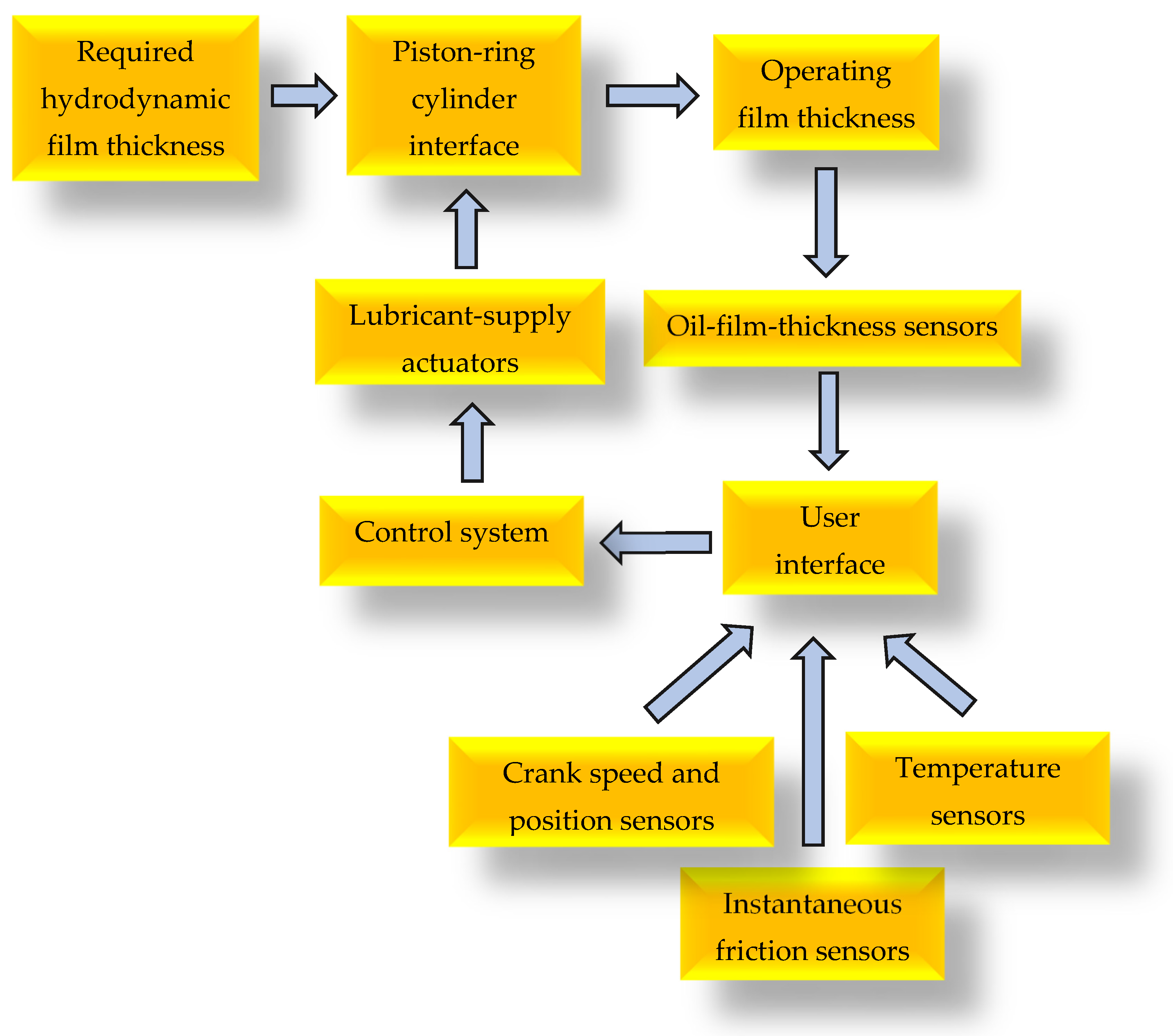
Tribotronic regulation of piston lubrication introduces sensing, algorithmic control, and actuation to deliver a controlled volume of lubricant to the piston rings. Using this kind of approach, it is possible to achieve a wide range of “optimisation goals” by employing “loss outputs”, such as friction, temperature and film thickness as feedback parameters, allowing the operating state of a tribological parameter, to be modified to a demand level for the “loss” [
2]. In this instance, cylinder to ring oil film thickness has been controlled. A schematic layout of the tribotronic piston-ring lubrication system, implemented in a motored engine-based test apparatus by the authors is shown in
Figure 6. It includes:
Capacitance-based lubricant-film-thickness sensors to measure the lubricant film thickness with sub-micrometre resolution;
Control software to process film-thickness-sensor data and compare it with demand values to evaluate the lubricant-delivery volume;
Actuator hardware to control the lubricant delivery to the cylinder liner;
A “floating liner” cylinder friction measurement system to assess the impact of the lubrication settings on piston assembly friction.
The oil-film-thickness sensors used were capacitance-based devices similar to those employed in other projects by these authors to measure film thickness [
21], as well as film extent and ring twist [
22]. However, a range of other devices for measuring this parameter, including ultra-sound probing and inductance sensing, are available [
23].
To evaluate the effectiveness of algorithmic control of lubricating-film thickness on engine friction, the test equipment also facilitated measurement of instantaneous piston-assembly friction, cylinder temperature (from embedded thermocouples), and engine speed via a crank angle encoder. Measurement of instantaneous piston-assembly friction was enabled through piezoelectric force transducers connected to a floating liner in a manner similar to other research [
24].
The data-acquisition system acquired instantaneous data for oil-film thickness, force, speed, and crank position at either fixed angle increments (between 0.25° and 1.0°), or at fixed time increments. Additional parameters derived from this data included minimum film thickness when passing each probe, the peak-friction-near-piston reversal points, and the maximum friction in the viscous-dominated mid-stroke plateau areas. Two actuation modes for delivering lubricant were available: (i) continuous micro-flow to emulate OCR delivery along the cylinder length and (ii) triggered pulses referenced to the top and bottom piston locations.
Accurate volumetric dosing of lubricant was achieved using stepper motor-driven syringe pumps which provided microlitre-resolved volumes and precise timing of lubrication events. Lubricant was distributed to the cylinder surface through rings of ports located at several axial positions along the cylinder. The arrangement of sensors and lubricant supply ports facilitates the possibility of many control strategies. Using a knowledge of the film-thickness-to-roughness ratio, the volume of lubricant required to maintain full-fluid film thickness can be calculated and supplied selectively at various axial locations.
Control strategies can involve one engine cycle or several. Different control strategies have not been explored in depth, but it is expected that conventional PID control logic would be an adequate approach, although more modern machine learning (ML)-based predictors may improve stability when engine speed varies quickly. Control strategies need to manage real-life challenges related to time delays which can arise from a range of sources. For example, actuation latency (where oil supply is delayed due to the time required to deliver lubricant through injectors with variable viscous drag in delivery lines), and delays related to hydrodynamic lubricant-transport mechanisms which move lubricant around the cylinder, especially under transient conditions, such as those following engine start-up [
25].
4.3. Tribotronic Control of Lubrication: Experimental Equipment
Gas-sealing and load support between the piston ring and cylinder arise from hydrodynamic pressure generated in thin lubricating film. The main purpose of tribotronic control is to optimise the lubricant delivery rate on a cylinder. For example, to achieve a reduction in friction due to complete removal of the oil-control ring, or to deliver a more effective lubricant distribution around high-risk regions (typically at top-land reversal points), where film thicknesses can be thinner, reducing wear and power loss in conventional systems.
Conventionally, over a number of decades, iteratively lower-viscosity lubricants have been employed to reduce viscous losses in hydrodynamic shear [
26], but this approach risks inadequate film development near reversal points. Higher-viscosity oils generate thicker films but increase shear losses and churning drag. Experiments show that ultra-low-viscosity oils (such as 0W-16/0W-20) can cut mean friction provided supply is well managed; otherwise, boundary losses rise [
19,
27]. Tribotronic control can decouple the trade-off between viscosity and film thickness to some extent.
This case study presents experimental investigations into lubrication control conducted using a single-cylinder, floating-liner system operated with an open cylinder head to isolate lubrication effects from combustion influences. The equipment was based on a Lister–Petter TR1 engine (stroke 101.6 mm, crank radius 50.8mm and an operating speed range of 900 rpm to 2500 rpm).
The piston assembly was fitted with two rings, namely a compression ring and a scraper ring, with no oil-control ring installed, allowing direct assessment of the lubrication within the piston–liner interface.
The speed of the apparatus engine was set to 25 rpm, and an SAE 20W50 lubricant was used at about 20 °C. This speed is not reflective of modern engines. However, the primary objective of this study was to conduct a “proof-of-concept” investigation. With the chosen speed and lubricant, a “dynamic similarity” between the lubricating conditions of the test and an operating engine in the low-speed range was examined. It is shown below that a degree of compatibility with operating conditions in the functioning engine at low speed was established.
The Hersey number,
H, was used as a basis for the dynamic similarity comparison.
H is given by
where
η is the dynamic viscosity of the lubricant,
U is the piston sliding speed (mean or instantaneous), and
P is the average normal contact pressure between the interfaces (the piston ring and the cylinder). Ideally, in experimental apparatus operation and typical engine operation,
H should be roughly the same for compatible lubrication conditions. Values of these variables for the experiment and typical engine operation are given in
Table 1.
As the cylinder was not closed, the mean ring–liner contact pressure was due only to the ring elastic pressure and was assumed to be constant, allowing dynamic similarity to be expressed as
ηU.
Table 1 shows that the product
ηU is similar in operating engines and the experimental equipment. This arises because at the elevated temperature of an operating engine (90C and 150C), the lubricant viscosity is lower than at an ambient temperature, and this lowered viscosity is compensated by higher speed in the Hersey number.
4.4. Tribotronic Piston-Ring Lubrication: Performance of Active System
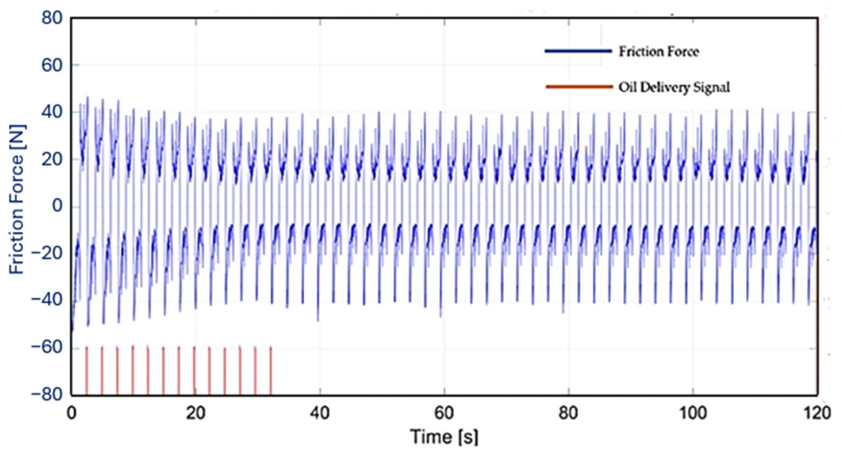
Figure 7 presents a graph of the instantaneous piston-assembly friction force alongside an automatic oil-injection sequence over a 120 s interval at a motored speed of 25 rpm. The piston had two rings and no oil-control ring. The orange lines denote discrete oil-delivery events. Each injection contributes to replenishing and building the hydrodynamic oil film, thereby mitigating asperity contact and reducing boundary friction. As the sequence progresses, the friction force is progressively stabilised, and after approximately 13 pulses and piston strokes, the oil-film thickness attains a steady-state level sufficient to minimise the friction force.
4.5. Tribotronic Piston-Ring Lubrication: Conclusions
Several conclusions can be drawn about the potential and significance of tribotronic piston-ring lubrication described in this case study.
From passive to adaptive: Conventional ring lubrication is effective but intrinsically passiveleading to oil control ring friction losses which are substantial. Tribotronic control converts the interface into an adaptive system that can preserve the same minimum film at critical points such as piston reversals while limiting mid-stroke viscous losses while eliminating the friction losses due to the oil control ring.
Control is better than compromise: By sensing film and friction and actuating oil delivery at the right angle and dose, tribotronics offers the potential to relaxe long-standing trade-offs between viscosity, ring tension, and oil supply, enabling lower-viscosity oils and lower-tension rings to be adopted.
Path to deployment: With continued progress in ruggedised sensors, faster low-power actuation, and control algorithms that account for a range of factors such as wear, tribotronic lubrication offers the possibility to deliver reductions in ring-pack friction alongside other advantages, thereby complementing parallel advances in lubricant formulation and ring design.
4.6. Tribotronic Piston-Ring Lubrication: Discussion
When evaluating tribotronic piston-ring lubrication systems, several issues and challenges emerge that must be addressed to ensure reliable operation and practical implementation. They include:
Sensor survivability and stability: Vibration, thermal cycling, and oil additives all challenge exposed film-thickness sensors. In situ calibration and robust construction will be required in a commercial implementation.
Time constants: Different parts of the system operate at different rates, and physical conditions require a finite time to reach equilibrium. Appropriate control systems are required to manage these rates effectively.
Non-uniform oil transport: Tribotronic control holds the potential to assist circumferential distribution and supply of lubricant through port phasing across a range of the non-ideal conditions, such as bore out of roundness, which prevail in real engines.
Packaging and cost: Additional technology will require additional cost, so there is a trade-off between the complexity and cost. Consequently, higher value engines will probably employ tribotronic systems first. For example, large marine engines.
5. Discussion: General Challenges in Tribotronics
Each of the above case studies presents a short discussion specific to a given machine element. However, it is possible to generalise some of the issues related to the active control of mechanical components.
5.1. Sensors
Sensor technology has developed significantly over recent decades, with reduced size, lower cost, increased capabilities, etc. Active control of machine elements requires sensors to be extremely durable and reliable, ideally lasting as long as the machine element itself. Two approaches that may assist in this objective include the use of suitable proxy measurements and a second more subtle approach involving using the surfaces of the component itself as the sensing element [
28]. Component temperature and lubricant temperature are long-established proxies in tribology. Rising friction due to lubrication failure leads to an increase in temperature of both the mechanical components and the lubricant. Therefore, in some instances, simple, robust temperature sensors may be suitable for crude assessments of lubrication conditions in systems such as transmissions [
29] and lubricant life [
30]. Using the concept of “surfaces as the sensor” may be a more challenging concept, but many technologies based on this approach have already been investigated in research projects [
28].
5.2. Control and Time Constants
Control principles are well established as a discipline in engineering. In cases where it is required to maintain a demand level of a parameter, a wide range of approaches can be adopted. There is no evidence that new control paradigms are required for tribotronic systems, and it is envisaged that conventional PID-type approaches will be perfectly adequate for the majority of devices. However, developments in ML may serve as valuable additions to conventional approaches to control by contributing to the long-term management of ensembles of similar systems or devices operating in severe adverse conditions.
5.3. Actuators
The design of actuators for tribotronic systems presents a significant challenge as it is often intellectually difficult to envisage methods for the active control of devices that have conventionally been passive for many decades since their first development. One semi-structured approach to such problems of innovation involves the application of a design concept commonly called “TRIZ”, a Russian abbreviation for “theory of inventive problem solving”. TRIZ involves principles of a design method developed by Genrich Altshuller in the latter stages of the 20th century [
31]. Altshuller examined many thousands of Russian patents and found that design principles could be encapsulated in 39 (now accepted to be 40) principles of invention. Applying these principles can lead to innovative solutions to unfamiliar challenges, and TRIZ has been found to be useful in many problems in engineering, including in the area of tribology [
32].
5.4. The Future for Tribotronic Control
The inclusion of tribotronics in engineering systems increases their complexity and cost, but the technology has the potential to significantly improve their capabilities and reliability. Additionally, the development is consistent with the more general development of mechatronics as a technology to improve machine performance.
The capability to digitise the control of tribological machine elements offers a range of potential benefits, including:
Control/optimisation of component wear rates;
Control/optimisation of friction-related losses;
Operation with different optimisation goals at different times, e.g., exchanging maximum lifetime for maximum efficiency;
Algorithmic change of component behaviour over time, e.g., to compensate for changes in tolerance due to wear;
Self-adjustment to account for changes in the precise fitting of different components of the same type;
Improvements in mechanical component performance with software updates;
Condition monitoring to manage maintenance, by providing details of lifetime duty and by managing the behaviour of ensembles of machines.
5.5. Financial and Environmental Impact
The financial and environmental impact of tribotronic technology can also be significant. The following discussions highlight how the use of tribotronics in the two components outlined above could be transformative if used on a wider scale.
5.5.1. Tilting-Pad Thrust Bearings
It is acknowledged that scaling data from smaller, laboratory scale, bearing test systems to describe the performance of larger full-scale installations is not a straightforward task [
33]. However, to gauge the order of magnitude of the potential impact of using the tribotronic system described in this paper at a larger scale, we have considered a straightforward extrapolation from our data to the case of a bearing installed in a medium-sized Francis turbine. The turbine and bearing parameters used are listed in
Table 2.
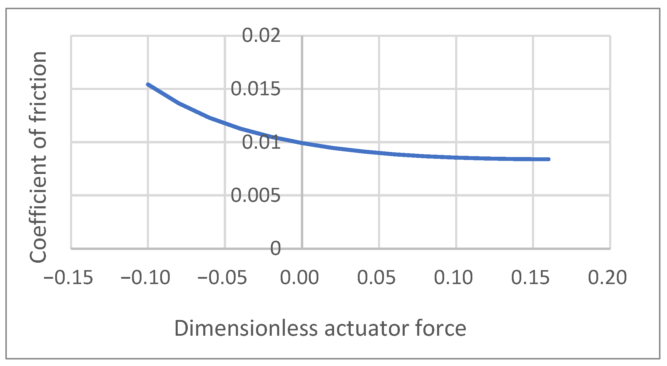
Figure 8 demonstrates how the effective “friction coefficient” of the laboratory bearing system can be adjusted as a function of the force applied to the pad-tilt actuator. Adjusting the actuator from its passive operation point (zero actuation force) towards its lower tangential asymptote (dimensionless force = 0.16) leads to a reduction in friction coefficient, which can be used to estimate the power loss for the tribotronic bearing. By applying 15% of the operating load, the friction force reduces from around 0.0099 to 0.0083. At the applied load of 3 MN, the mean tangential friction force decreases from around 27.9 kN to 25.2 kN. Operating at an average speed of 15 ms
−1, the corresponding power loss falls from 0.416 MW to 0.353 MW, a saving of 63 kW (15% reduction). A simple calculation suggests that the actuation force required to tilt each pad to its optimal state is 80 kN. Assuming a hydraulic ram is used as the actuator, the power required under low rate is only around 300 W, a relatively small energy expenditure in exchange for substantial savings.
It is difficult to estimate the global impact of installing tribotronic control on all Francis turbines worldwide. However, there is approximately 780 GW of hydropower installed worldwide and approximately 60% of these have Francis turbines [
34]. If these turbines matched the system analysed above, a simple estimate suggests that around 70 GW of power could be saved in this sector alone by applying tribotronic technology.
Savings in energy use generally lead to savings in emissions. It is not possible to directly predict emissions savings because they depend on the means of generating the power that has been saved. However, if the energy savings of 70 GW suggested above were translated into CO
2 savings arising as a result of lowered energy generation, based on the 2024-25 UK Government fuel mix disclosure (382 g CO
2 per KWh) [
35], somewhere in the region of 234 million tonnes of CO
2 emissions would be mitigated annually. These are considerable savings and probably a generous estimate, but even by taking a much more conservative estimate of 5% power loss reduction, the savings would still be of the order of gigawatts.
5.5.2. Tribotronic Cylinder Lubrication
Sherrington, Calderbank and Smith have conducted a separate detailed study [
36] to consider the case of applying tribotronic control of the lubrication of the piston assembly in large two-stroke marine engines. Ship cylinder lubricants are conventionally applied at a rate which ensures that corrosion inhibitors (which are mixed into the lubricant) are applied at a satisfactory rate. Generally, this leads to overapplication of lubricant, especially at high engine loads and speeds when more corrosion inhibitor is required. Over-lubrication leads to unnecessary consumption of lubricant and elevated CO
2 emissions as the injected lubricant is almost completely combusted and exhausted as emissions on each engine cycle. The purpose of the tribotronic system was to allow a separation between the functions of lubricant and the corrosion inhibitor, allowing them to be introduced individually at rates appropriate to their own independent functions. The effect of reductions in lubricant consumption gained by using tribotronic cylinder lubrication in this manner for ships of differing engine capacity were estimated. A typical result estimated that a fleet of 30 ships with an engine capacity of 50 kWh, could save 2160 tonnes of lubricant per year, reducing CO
2 emission by around 6849 tonnes [
36]. At 2025 prices, this corresponds to an annual saving of up to US
$3,412,000 on cylinder lubricant.
5.5.3. Overview of Savings
Both of these examples lead to potentially enormous savings in energy and emissions. The estimates assume that a large number of components operate in a tribotronic mode, and the estimates of the savings involve many assumptions and simplifications. However, if even 10% of these savings could be realised through tribotronics, the impact of developing this technology and implementing it in these applications alone would represent a considerable reduction in energy consumption and emissions.
5.6. New Developments
Tribotronic (active) control of machine elements has been made viable by developments in sensor technology, digital systems and communication over the last two decades. Further developments in smart materials and manufacturing techniques, especially additive manufacturing along with machine learning as a control tool, are likely to further improve capabilities to integrate components such as actuators and sensors in machine elements and implement “intelligent” control. This could possibly even lead to completely novel designs of elements that replace the passive systems in common use today. High cost or very large volume assets are likely to see the greatest developments first, and the opportunity for mass production and large-scale applications will probably be the key to further developments in general use.
6. Further Work
Globally, further research efforts in tribotronics are likely to address both technical innovation in research settings and developments in the commercial environment. Commercial tribological systems which incorporate sensors and communication are becoming increasingly common. They include rolling element bearings [
37] and plain polymer bearings [
38]. The steadily increasing capabilities and feasibility of implementing condition monitoring suggest this trend is likely to continue. Condition monitoring is now routinely applied, not just to engineering systems of high financial value, but also to small safety-critical assets (which may be of low value). This progression towards condition monitoring, along with other engineering innovations such as additive manufacturing, smart materials, embedded computing power and increasing powerful communication networks, indicate that further steps towards actuation and control of tribological elements are likely
The authors will continue their research into tribotronics, addressing the further challenges in the areas outlined in this paper as well as developing work on other components such as seals and rolling element bearings.
7. Conclusions
The application of good practices in lubrication science has contributed to the development of more reliable and better-performing machines for over century. However, many improvements in tribology in the past have been incremental, involving, for example, improved understanding of lubrication principles, better material performance, new lubricant formulations, surface coating technologies, etc. It is becoming increasingly apparent that if the tribological performance of machine elements is to progress further, a new paradigm to underpin a radically different approach is required.
Ciulli [
39] has reviewed the impacts that can result across a range of engineering elements, such as energy saving, manufacturing, and robotics, when technologies such as sensing and data sharing are introduced into tribological elements to form cyber-physical systems. Ciulli [
39] also notes that additional benefits can be gained through the addition of sensing, actuation and control to tribological elements through tribotronics, and it is demonstrated directly in this paper how tribotronics provides a viable and effective approach which can lead to step changes to the specific problem of controlling the frictional performance of machine elements. The electronic and digital nature of tribotronics also means that it can contribute to Industry 4.0 in tandem with machine learning to aid further developments beyond those benefits outlined by Ciulli. In addition, tribotronics can also act as a tool for the mitigation of climate change, potentially supporting the sustainable development goals [
40] by reducing power consumption, emissions, waste flows and component wear.
Given that the potential benefits are transformative, the authors believe it is inevitable that tribotronics will form a pathway to the design and operation of the machines of the future.



 ,
,