Abstract
Many low-temperature applications, such as rocket engines and liquefied natural gas (LNG) transport pumps, necessitate ultra-low-temperature operational environments. In these conditions, the properties of lubricating oils and greases are significantly influenced by temperature, leading to the widespread adoption of solid lubrication. Currently, there is no international research regarding the influence of bearing coatings on the subsurface stress distribution in raceways. The Lundberg–Palmgren (L-P) theory states that subsurface stress variations govern bearing lifespan. Therefore, this paper utilizes existing formulas and Python programming to calculate the subsurface stress field of the inner raceway in a MoS2 solid-lubricated angular contact ball bearing. Furthermore, it analyzes the impacts of factors such as coating material properties, slide-to-roll ratio, traction coefficient, and load on its subsurface stress field. The results reveal that for solid-lubricated ball bearings, as the load increases, the maximum subsurface stress shifts closer to the center of the contact area, and the maximum subsurface shear stress becomes more concentrated. As the traction coefficient increases, the stress on the XZ-plane side increases and its position moves closer to the surface, while the opposite trend is observed on the other side. Additionally, the maximum value of the subsurface von Mises stress is approximately 0.64P0, and the maximum value of the orthogonal shear stress component τyz in the subsurface is approximately 0.25P0.
1. Introduction
As core components of rotating machinery, bearings’ fatigue life is a critical reliability indicator. Over 80% of bearing failures are attributed to contact fatigue, manifesting as spalling or cracking.
1.1. The Significance of Subsurface Stress in Fatigue Theory
Current theories on contact fatigue life primarily derive from the L-P model [1]. This model integrates Hertzian contact theory, Weibull statistics, and extensive test data. The central premise of the L-P life theory is that the fatigue failure mechanism is driven by subsurface stress, suggesting that the fatigue life of bearings is governed by the initiation and propagation of cracks induced by the maximum alternating shear stress within the material. Miyashita [2] conducted rolling contact fatigue tests, confirming a strong correlation between the range of maximum shear stress and the initial crack initiation depth. Miyashita confirmed through rolling contact fatigue tests that maximum shear stress range correlates strongly with initial crack depth. Furthermore, these tests revealed decreasing maximum shear stress depth with increasing surface tangential force. Qin et al. [3] discovered that friction results in an asymmetric subsurface stress state, with both the orthogonal shear stress in the subsurface layer and the stress ratio related to rolling contact fatigue damage in this layer increasing with friction. Mizozoe et al. [4] examined the subsurface stress of thrust bearings in water, observing crack propagation under rolling contact fatigue conditions in a watery environment. They found that subsurface cracks emerge from regions where the subsurface shear stress is maximized. Greco et al. [5] investigated the subsurface stress distribution under elastohydrodynamic lubrication, revealing that fatigue resistance is also influenced by the presence and size of surface pits on the material. Li et al. [6] confirmed that subsurface layers sustain maximum fatigue damage in backup rolls under alternating contact stress, characterized by microstructural fragmentation and elevated dislocation density. Fu et al. [7] conducted research on the simulation of rolling contact fatigue and life prediction for bearing steel used in aero-engines, noting that, under ideal conditions, rolling contact fatigue originating from the subsurface represents a critical failure mode for bearing steel. Increasing contact stress induces an elastic-to-plastic transition in bearing materials. Collectively, these studies demonstrate that subsurface stress profoundly impacts bearing fatigue life.
1.2. Calculation Methods for Subsurface Stress
Current subsurface stress calculation methods are confined to finite element analysis (FEA) and numerical methods. The finite element method (FEM) discretizes models into elements, applies boundary conditions, and performs iterative nodal calculations to determine internal stress fields. However, the computational accuracy of FEM is subject to significant uncertainties. Mesh refinement in contact regions is essential for improved accuracy. The level of mesh refinement greatly influences the computational outcomes, with the refined mesh potentially comprising hundreds of thousands or even millions of elements, which can result in excessively long computation times.
Peng et al. [8] employed the FEM to calculate the internal stress distribution of contacting bodies under rolling–sliding conditions. Wang et al. [9] applied FEM simulations to analyze subsurface stress in single row four-point contact slewing bearings, demonstrating friction coefficient effects on subsurface maximum shear and equivalent stresses. Yang et al. [10] analyzed the subsurface stress of elastic composite cylindrical roller bearings and conventional cylindrical roller bearings using the finite element method, finding that the subsurface stress in elastic composite cylindrical roller bearings is closer to the surface and exhibits lower stress values compared to conventional cylindrical roller bearings.
Calculating subsurface stress using the finite element method (FEM) requires subdividing the model into discrete elements, applying boundary conditions, and iterating on each node in the model. However, the computational accuracy of FEM is subject to significant uncertainties. To achieve more precise results, it is essential to refine the mesh in the contact region. The degree of mesh refinement greatly influences the computational outcomes, with the refined mesh potentially comprising hundreds of thousands or even millions of elements, which can lead to excessively long computation times. In contrast, numerical calculations based on theoretical equations offer rapid computation speeds while maintaining reasonable accuracy. Although these calculations may not perfectly reflect actual working conditions, the overall distribution and trend of subsurface stress remain relatively accurate. Numerical calculations are crucial for studying subsurface stress and bearing fatigue life. Zheng et al. [11] conducted numerical calculations of the internal stress distribution in rolling bearings using MATLAB, addressing both line contact and point contact forms. They analyzed the effect of the contact ellipse’s k-value on the subsurface stress distribution in point contact.
Conversely, numerical methods based on theoretical equations offer computational efficiency with reasonable accuracy. Although imperfect representations of actual conditions, these methods accurately capture subsurface stress distribution trends. Numerical calculations are crucial for studying subsurface stress and bearing fatigue life.
1.3. Research on MoS2 Solid Lubrication
Solid lubrication coatings have emerged as a significant research focus in recent years, notably enhancing the fatigue life of bearings. In ultra-low-temperature environments, solid lubricating materials with low friction coefficients, such as silver (Ag), polytetrafluoroethylene (PTFE), and molybdenum disulfide (MoS2), are commonly utilized as cage materials or raceway coatings for rolling bearings. During bearing operations, these solid lubricating materials form transfer films on the rollers and raceways through their inherent friction and wear, thereby achieving effective lubrication. In the rotating systems of liquefied natural gas (LNG) transport pumps, ball bearings serve as critical rotating support components. Unlike traditional ball bearings, lubricating oils or greases cannot be employed in ultra-low-temperature media due to their constraints. Consequently, solid lubrication coating technology is implemented to apply or plate solid substances onto the interfaces of friction pairs for effective lubrication. The most prevalent solid lubricants in ultra-low-temperature environments include polytetrafluoroethylene (PTFE), molybdenum disulfide (MoS2), graphite, and other materials. Among these, PTFE demonstrates excellent adaptability to extreme environments and consistent friction coefficients, with potential for further enhancement of wear resistance and friction coefficients through surface modifications. MoS2, characterized by its layered structure, exhibits remarkable anti-wear and lubricating properties at low temperatures, along with a broad working temperature range. Graphite, known for its abundant availability, low cost, and effective lubrication, also features a layered structure. However, it exhibits relatively weak cohesion and is susceptible to the influence of gases and liquids in the working environment, with its layers prone to cleavage under external forces. Therefore, MoS2 demonstrates superior lubricating performance and environmental adaptability as a solid lubricant for bearings. It forms a transfer film on the raceway, and through the rolling and pressing actions of the rolling elements on the raceway, uniformly distributed annular traces are created on the raceway surface. A lubricating effect is achieved when these traces are transferred to the rolling elements.
Kadiric et al. [12] quantitatively investigated the effects of coating properties, thickness, and surface roughness on subsurface stress amplitude beneath coated contacts. They identified coating Young’s modulus and thickness as primary factors controlling subsurface stress amplitude and depth. Tasuku et al. [13] discovered that interlayer sliding and disordered rotation in bilayer MoS2 sheets are essential for achieving low-friction states at atomic scales. Kalyan et al. [14] attributed the primary reason for the friction reduction observed in MoS2 to its shear-prone crystalline structure and utilized a slider-crank mechanism to explore the effects of both soluble and insoluble MoS2 on material friction characteristics under boundary lubrication conditions. Singh et al. [15] employed a pin-on-disk tribometer to investigate the transfer film formation mechanism and the friction-reducing effects of ultra-high molecular weight polyethylene (UHMWPE) and molybdenum disulfide (MoS2) composite coatings under dry sliding and grease lubrication conditions. Li et al. [16], considering both friction reduction and wear resistance aspects of coatings, prepared a surface micro-dimpled composite MoS2 nickel-based coating and verified its improved combined performance in friction reduction and wear resistance through ball-on-disk friction and wear tests. Singh et al. [17] compared the friction reducing effects of various composite materials and found that, under high PV factors (the product of contact pressure and sliding velocity), epoxy resin-based polymer coatings filled with UHMWPE, MoS2, Kevlar, and base oil effectively reduced the friction and wear of sliding bearings. Zhang et al. [18] employed laser surface texturing technology to incorporate MoS2 powder into surface coatings of other materials and conducted experimental investigations via ball-on-disk tests. The results demonstrated that MoS2 exhibits excellent friction-reducing properties.
Currently, most research on MoS2 coatings emphasizes friction reduction; there is no international research regarding the influence of bearing coatings on the subsurface stress distribution in raceways. According to the L-P theory, the magnitude and distribution of subsurface stress generally determine the fatigue life of bearings. Therefore, this paper conducts relevant research to explore the impact of MoS2 coating on the subsurface stress of bearings and calculates its subsurface stress distribution.
2. Numerical Calculation Method for Subsurface Stress of Bearings
Although subsurface stress is a crucial factor influencing the fatigue life of bearings, its location within the material complicates exploration and analysis through traditional surface measurement techniques. This specificity presents challenges in calculating, measuring, and analyzing subsurface stress.
Based on the computational equations proposed in reference [19], this paper has developed a Python program using Python 3.7 to conduct numerical computations of the stress distribution in the subsurface of bearings. The calculation of subsurface stress in bearings considers two types of contact forms: line contact and elliptical contact. The contact form for ball bearings is elliptical, while that for roller bearings is line contact. Elliptical contact is one of the most prevalent modes in Hertzian contact theory. This study primarily focuses on angular contact ball bearings, which exhibit elliptical contact. The bearing coordinate system is illustrated in Figure 1a, where the Z-axis points into the subsurface, the Y-axis represents the direction of bearing motion, and the X-axis denotes the axial direction of the bearing. The YZ plane is the rolling plane of the bearing. The contact area between the steel ball and the raceway in Figure 1a is shown in Figure 1b. Elliptical contact is crucial for the numerical calculation of stresses in ball bearings, and the relevant equations for elliptical contact are presented below.
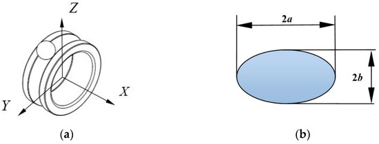
Figure 1.
(a) Definition of the coordinate system; (b) shape of the contact area.
Q is the normal contact load between the rolling element and the raceway. P0 is the maximum contact stress at the center of the contact area. a is the semi-width of the major axis of the contact ellipse. b is the semi-width of the minor axis of the contact ellipse. δ is the contact elastic deformation.
The equations for the three principal stresses, as well as the subsurface orthogonal shear stress and subsurface maximum shear stress, can all be found in reference [19].
The subsurface stress field of the bearing is obtained by the superposition of two components: the Hertzian contact stress field and the stress field induced by tangential frictional forces.
Here, σx represents the principal stress in the X-axis direction, σxN is the subsurface stress field component induced by Hertzian contact, and σxf is the subsurface stress field component caused by tangential frictional force. τyz denotes the orthogonal shear stress in the YZ plane, τyzN is its Hertzian contact component, and τyzf is its tangential stress field component. The same notation applies analogously to other components. This paper primarily focuses on the subsurface stresses in the YZ and XZ planes of the bearing.
The equations for the subsurface stress field induced by Hertzian contact are presented as follows:
In the equation, k = b/a, ν is the Poisson’s ratio of the raceway material. x, y, and z represent coordinates beneath the subsurface. The calculation equation for s is as follows:
The calculation equation for L is as follows:
The equations for the subsurface tangential force caused by friction are presented as follows:
In the equation, f is the friction coefficient, and H, G, L, and s are defined as intermediate variables in the analysis. The calculation equations for H and G are as follows:
I1, I2, I3 are elliptic integrals, and the equations are as follows:
is the eccentricity of the contact ellipse, and the equations are as follows:
τ-max represents the maximum shear stress, and θ is the angle between τ-max and the rolling plane.
Based on all the formulas described above, the calculation procedure for the subsurface stress of a ball bearing can be summarized as follows: The first part involves force analysis, where the maximum load on a single roller is calculated according to the bearing load. The second part focuses on calculating the major and minor axes of the contact area and determining the contact stress. The final part is concerned with computing the stress distribution in the subsurface beneath the contact area.
3. MoS2 Solid Lubricant Traction Test
This paper takes the 7206AC angular contact ball bearing as the research object. To conduct further investigation into the subsurface stress of the 7206AC bearing under MoS2 solid lubrication, the following work has been carried out in this study.
3.1. Research on the Traction Model of MoS2 Solid Lubrication
In his research on the friction characteristics of rolling bearings, Gupta categorized test studies into two types based on different contact modes: sliding contact and sliding–rolling contact. Under sliding contact conditions, the primary focus is on the nominal sliding contact friction coefficient. In the case of sliding–rolling contact, the tractive force is generally regarded as a function of the sliding velocity. This approach facilitates the coupling between the tractive force and sliding, which holds significant practical importance for the study of the dynamic behavior of rolling bearings.
Gupta conducted extensive test research and discovered that, for most solid or liquid lubricants, there exists a specific relationship (as illustrated in Figure 2) between the traction coefficient and sliding. As depicted in the figure, the traction coefficient increases with an increase in sliding, reaches a maximum value, then slightly decreases, and finally stabilizes at an ideal value. This indicates that both solid and liquid lubrication share similar lubrication mechanisms. Nevertheless, despite some simplified assumptions regarding the working environment and film characteristics, applying a liquid lubrication model to a solid film model remains highly complex. This complexity restricts its application in the study of bearing dynamics.
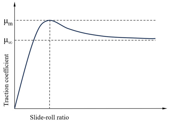
Figure 2.
The relationship between the traction coefficient and sliding velocity.
Given the complex lubrication characteristics of solid lubricating films and the need for simplicity in the model, Gupta [20] proposed the following solid slip model, as expressed by Equation (33), which represents the traction/friction coefficient as a function of sliding velocity.
In the equation, μ represents the traction coefficient (or friction coefficient), u denotes the sliding velocity, and A, B, C, and D are undetermined coefficients typically associated with material properties and test conditions such as sliding velocity, contact pressure, and temperature. Furthermore, these coefficients may also be influenced by surface finish, the chemical properties of the contacting surfaces, and the relevant characteristics of the solid lubricant. In order to investigate the subsurface stress distribution pattern of bearings with MoS2 coating, this paper conducts the following research on the traction coefficient of MoS2.
3.2. Working Condition Transition
The contact state and wear patterns between the steel ball and raceway in a solid-lubricated bearing differ from those observed in a ball-on-disc test. To better simulate actual working conditions, during the ball-on-disc traction test, the relative sliding velocity between the steel ball and raceway should be converted into the corresponding sliding velocity based on the contact stress calculations between them, in accordance with Hertzian contact theory. This paper conducts further research using a 7206AC angular contact ball bearing as the subject. The structural parameters of a MoS2-coated 7206AC angular contact ball bearing are presented in Table 1.

Table 1.
Bearing-related parameters.
3.2.1. Velocity Conversion
The conversion of velocities between the bearing and the ball-on-disc setup is relatively straightforward. Specifically, the linear velocity at the contact point of the steel ball and the raceway in the bearing corresponds to the linear velocity at the contact point of the ball and the disc in the ball-on-disc test setup.
The self-rotation speed of the steel ball in the bearing is as follows:
γ is the dimensionless geometric parameter of the bearing. ni is the rotational speed of the bearing inner ring. The linear velocity of the steel ball at the contact point is as follows:
If there is skidding in the bearing with a slide-to-roll ratio denoted as s, the linear velocity of the raceway at the contact point can be translated as
Since the axes of rotation for the ball and disc specimens are mutually perpendicular and coplanar, the influence of spin on the rolling velocity U can be neglected. Let the linear velocity of the ball specimen at the contact point with the disc specimen be U1, and the linear velocity of the disc specimen at the contact point with the ball specimen be U2.
The linear velocity of the bearing steel ball at the contact point is equal to the linear velocity of the ball specimen at the contact point with the disc specimen.
The linear velocity of the raceway at the contact point is equal to the linear velocity of the disc specimen at the contact point with the ball specimen.
The rolling velocity between the ball and disc specimens is as follows:
The sliding velocity between the ball and disc specimens is as follows:
The slide-to-roll ratio is defined as the ratio of the sliding velocity to the rolling velocity, and its expression is as follows:
During the test, the rotational speeds of the ball and disc specimens are adjusted using an inverter, transforming their contact state from pure rolling to a slide-roll contact state. The rotational speeds of the ball specimen and the disc specimen are as follows:
In the equation, R1 is the radius of the ball specimen, in meters (m), and R2 is the distance from the contact point to the center of the disc specimen, in meters (m).
In a set of tests, the rolling velocity between the ball and disc specimens is maintained constant, while the sliding velocity ΔU between them is varied.
During the test, an inverter is utilized to adjust the rotational speeds of the ball and disc specimens, transforming their contact state from pure rolling to a slide-roll contact state. The relationship expression between the rotational speeds of the ball and disc specimens and the slide-to-roll ratio is as follows:
In the equation, s is the slide-to-roll ratio, n1 is the rotational speed of the ball specimen, and n2 is the rotational speed of the disc specimen.
3.2.2. Load Conversion
According to Hertzian contact theory, the contact between the bearing steel ball and the raceway, as well as between the ball and the disk, is regarded as the contact between two elastic curved surfaces. The principal curvatures of the steel ball in the principal planes I and II are denoted as ρ1I and ρ1II, respectively, while the principal curvatures of the bearing raceway in the principal planes I and II are denoted as ρ2I and ρ2II, respectively. The calculations for the sum and difference of curvatures at the contact point for the two bodies are presented as follows:
In the equations, the principal curvatures of the bearing contact point in the principal planes I and II are obtained from Table 2.
Table 2.
Calculation formula of principal curvature of contact point of a solid-lubricated bearing.
The Hertzian contact stress of the bearing is given by Equations (1)–(4). For the contact between the ball and the disk, denoted as P1, it implies that the contact stress between the bearing steel ball and the raceway is equal to that between the ball and the disk.
The difference between the ball–disk contact and the bearing contact lies in the fact that the curvature of the steel disk (or plate, assuming it is a flat surface) is zero. The equation for the curvature radius of the ball remains the same as in the ball-bearing contact. The equation for calculating the contact stress between the ball and the disk is as follows:
F represents the test load applied between the ball and the disk.
3.3. Tests and Results
This paper presents the results of ball-on-disk traction tests conducted with MoS2 (molybdenum disulfide) coatings to investigate the variation of the traction coefficient of MoS2 solid lubrication with time under the same load. The ultra-low temperature, high-speed, and heavy-load solid lubrication traction force testing machine used in the tests is illustrated in Figure 3. It comprises a loading module, a lubrication module, a temperature control module, a power module, a traction force testing module, and an ultra-low temperature system. The schematic diagram of the traction testing machine is shown in Figure 4. The ball-on-disk test specimens are depicted in Figure 5.
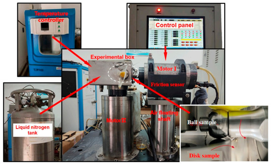
Figure 3.
The ultra-low temperature solid lubrication traction force testing machine.
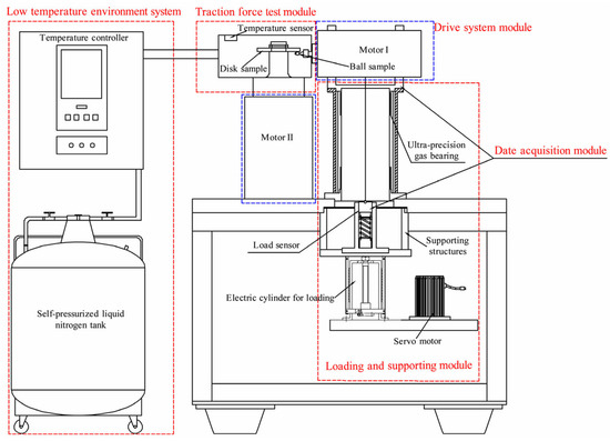
Figure 4.
Structure diagram of testing machine.
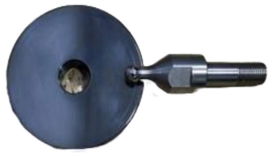
Figure 5.
MoS2-coated disk specimens and steel ball specimens.
Surface microtopography of both the uncoated steel disk and the MoS2-coated steel disk was characterized using an JSM-7800F scanning electron microscope (JEOL Ltd., Tokyo, Japan), with the surface morphologies magnified by 500 times in Figure 6. Comparative analysis revealed that the MoS2 coating exhibited uniform texture, smooth surface finish, and superior preparation quality.
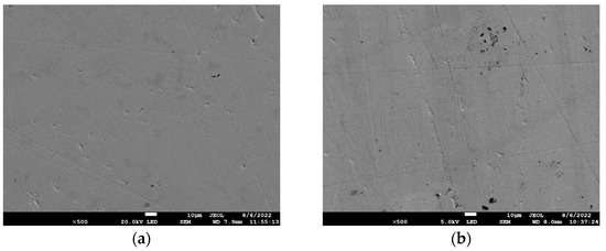
Figure 6.
(a) Original steel surface; (b) original surface of MoS2 coating.
The key parameters of the ball-on-disk specimen and the test working conditions in the traction test are shown in Table 3 and Table 4, respectively.
Table 3.
Key parameters of the ball-on-disk specimens.
Table 4.
Traction tests working conditions.
The traction characteristic test for the solid lubrication coating on the G95Cr18 material used in ultra-low temperature bearings involves measuring the variation of the friction force F with time between the steel ball and different solid lubrication-coated disk specimens of G95Cr18 material under given sliding speeds (ΔU) and loads (W). The resulting curves showing the variation of the traction coefficient μ = F/W with time for different solid lubrication coatings on the G95Cr18 material are illustrated in Figure 7. It can be observed that the traction coefficient initially decreases and then stabilizes almost uniformly across all cases. This phenomenon occurs because, after a period of ball-on-disk operation, a transfer film of MoS2 solid lubricant forms on the steel ball surface, leading to the gradual stabilization of the traction coefficient.
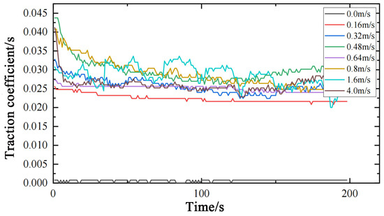
Figure 7.
Traction coefficients of MoS2 at different sliding speeds under a ball–disk load of 68 N.
By averaging the test data (comprising 200 points) collected over 200 s under each of the aforementioned working conditions, the traction coefficient value for the specific condition can be obtained. The traction coefficient curve fitted using Gupta’s solid lubrication model is presented in Figure 8. It is observed that as the sliding velocity increases, the traction coefficient initially rises, then decreases, and ultimately stabilizes.
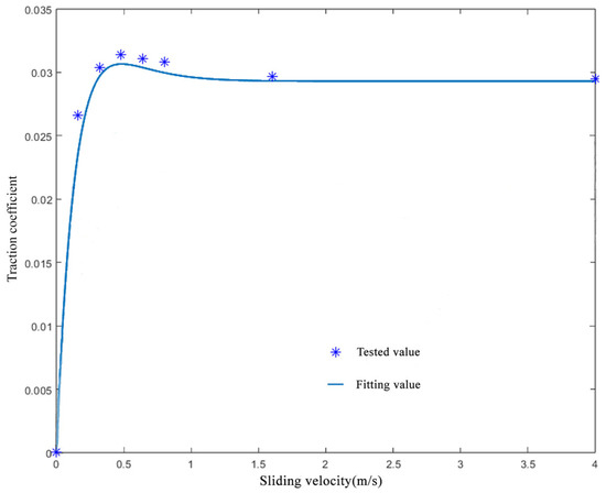
Figure 8.
The relationship between the traction coefficient and sliding velocity under a ball–disk load of 68 N.
As shown in Figure 8, under a load of 68 N, the traction coefficient reaches its minimum value, approaching zero, when the sliding speed is 0 m/s. The average traction coefficient attains a maximum of 0.032 at a sliding speed of 0.48 m/s. As illustrated in Figure 8, the traction coefficient stabilizes at approximately 0.03 once the sliding speed exceeds 1.5 m/s. Given that the difference between the maximum value and the steady-state value is negligible, this study conducts a comparative analysis under dry friction conditions to investigate the influence of the traction coefficient on the subsurface stress of bearings, with the traction coefficient set at 0.1 for dry friction scenarios [21]. An analysis will be conducted on the subsurface stress of the bearing under these three working conditions, as well as three additional load cases from reference [22].
The traction coefficients corresponding to each working condition are summarized in Table 5.
Table 5.
Working condition parameters.
4. Subsurface Stress Calculation and Analysis
Under ultra-low temperature conditions, the material properties of GCr15 bearing steel undergo changes. The Young’s modulus slightly increases and is measured as 2.2 × 10⁵ MPa, while the Poisson’s ratio slightly decreases and is recorded as 0.29. In this paper, the semi-width of the contact minor axis, denoted as b, corresponds to the unit length along the Y and Z axes, whereas the semi-width of the contact major axis, denoted as a, corresponds to the unit length along the X axis. Given that the bearing works with the outer ring fixed and the inner ring rotating, and the load is applied to the inner ring, this paper focuses on the subsurface stress of the inner raceway as the research object. Based on the program developed in Section 2, calculations were conducted by inputting the boundary conditions listed in Table 5. The resulting subsurface stress of the bearing inner raceway is presented as follows:
4.1. The Influence of the Traction Coefficient on Subsurface Stresses
The orthogonal shear stresses in the subsurface under working conditions 1, 2, and 3 are illustrated in Figure 9.
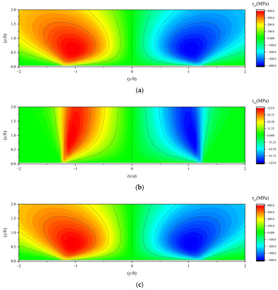
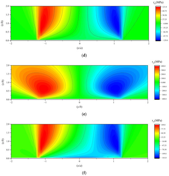
Figure 9.
(a) The τyz under working condition 1; (b) the τxz under working condition 1; (c) the τyz under working condition 2; (d) the τxz under working condition 2; (e) the τyz under working condition 3; (f) the τxz under working condition 3.
The principal stress along the x-axis in the subsurface of a 7206 angular contact ball bearing under working conditions 1, 2, and 3 is illustrated in Figure 10.
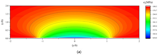
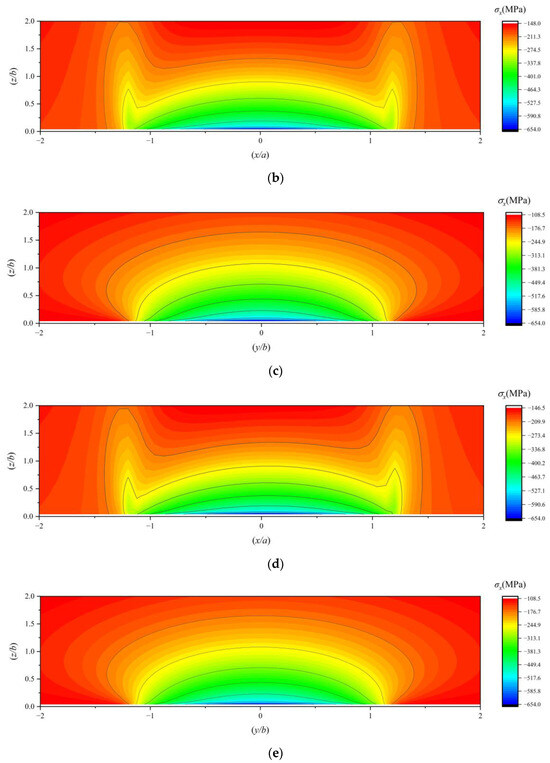
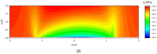
Figure 10.
(a) The YZ-plane distribution of the stress component σX under working condition 1; (b) the XZ-plane distribution of the stress component σX under working condition 1; (c) the YZ-plane distribution of the stress component σX under working condition 2; (d) the XZ-plane distribution of the stress component σX under working condition 2; (e) the YZ-plane distribution of the stress component σX under working condition 3; (f) the XZ-plane distribution of the stress component σX under working condition 3.
The subsurface von Mises stress in the subsurface of a 7206 angular contact ball bearing under working conditions 1, 2, and 3 is illustrated in Figure 11.
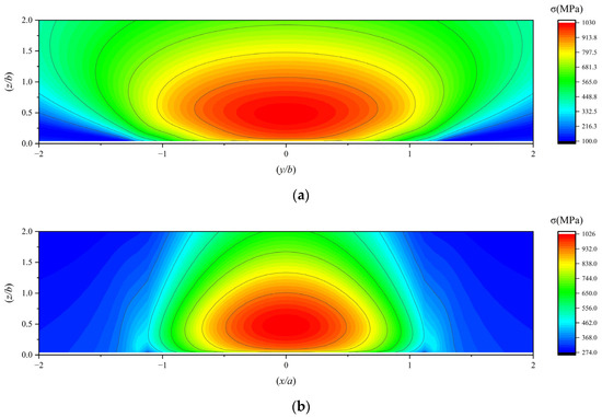
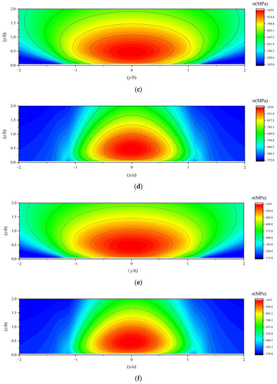
Figure 11.
(a,b) The subsurface von Mises stress under working condition 1; (c,d) the subsurface von Mises stress under working condition 2; (e,f) the subsurface von Mises stress under working condition 3.
The maximum shear stress in the subsurface of a 7206 angular contact ball bearing under working conditions 1, 2, and 3 is illustrated in Figure 12.
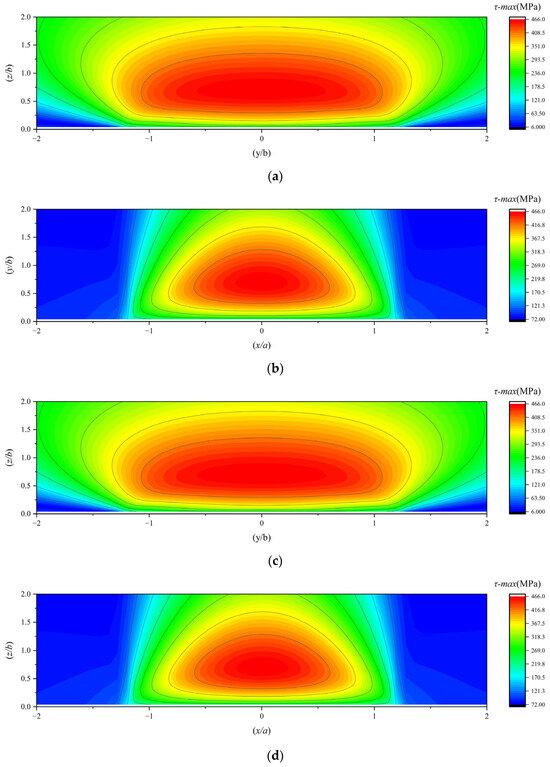
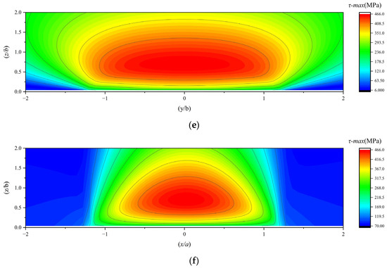
Figure 12.
(a,b) The maximum subsurface shear stress under working condition 1; (c,d) the maximum subsurface shear stress under working condition 2; (e,f) the maximum subsurface shear stress under working condition 3.
Since fatigue failure in rolling contact surfaces is a statistical phenomenon that depends on the volume of material subjected to stress, the depth at which subsurface stress occurs also holds practical significance. This study also investigates the locations of subsurface stresses. To investigate the effect of the traction coefficient on the location of the maximum orthogonal shear stress (τxz) in the subsurface, the magnitude and location of the maximum τxz under working conditions 1, 2, and 3 are summarized in Table 6.
Table 6.
Magnitude and location of the maximum subsurface orthogonal shear stress component τxz under working conditions 1, 2, and 3.
Based on the comprehensive research findings, the following conclusions can be drawn:
When the traction coefficient is zero, the stress fields exhibit symmetry about the central axis and uniform distribution. In contrast, when the traction coefficient is non-zero, it has a negligible impact on the stress distribution in the YZ plane. However, in the XZ plane, the stress field generally tilts. This indicates that the predominant sliding friction in the bearing occurs in the XZ plane, which is perpendicular to the rolling direction. The YZ plane, serving as the rolling plane of the bearing, primarily experiences rolling friction, which is relatively insignificant compared to sliding friction.
As the traction coefficient increases, the stress positions on one side of τxz move farther away from the surface, while those on the other side approach closer to it. When the traction coefficient reaches a certain level, the stresses on the side closer to the surface show a tendency to concentrate towards the surface. Simultaneously, the XZ-plane stress of the maximum principal stress along the X-axis (σx) also concentrates towards the surface.
The distribution patterns of the subsurface von Mises stress and the maximum subsurface shear stress are similar; their stress values initially increase and then decrease with increasing depth from the surface.
4.2. The Influence of the Load on Subsurface Stresses
The orthogonal shear stresses in the subsurface under working conditions 4, 5, and 6 are illustrated in Figure 13.
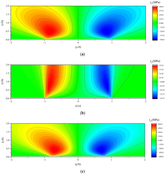
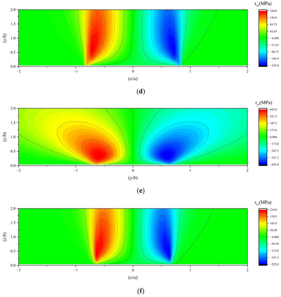
Figure 13.
(a) The τyz under working condition 4; (b) the τxz under working condition 4; (c) the τyz under working condition 5; (d) the τxz under working condition 5; (e) the τyz under working condition 6; (f) the τxz under working condition 6.
The subsurface von Mises stress in the subsurface of a 7206 angular contact ball bearing under working conditions 4, 5, and 6 is illustrated in Figure 14.
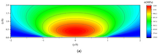
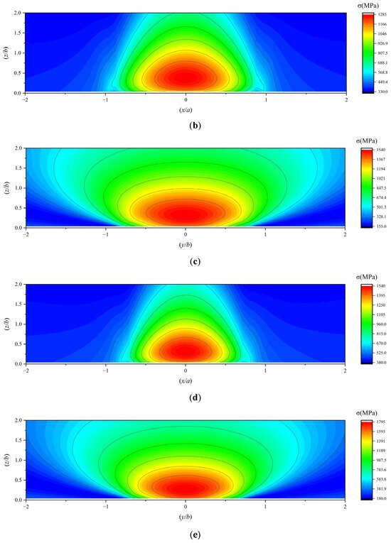
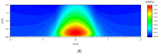
Figure 14.
(a,b) The subsurface von Mises stress under working condition 4; (c,d) the subsurface von Mises stress under working condition 5; (e,f) the subsurface von Mises stress under working condition 6.
The maximum shear stress in the subsurface of a 7206 angular contact ball bearing under working conditions 4, 5, and 6 is illustrated in Figure 15.
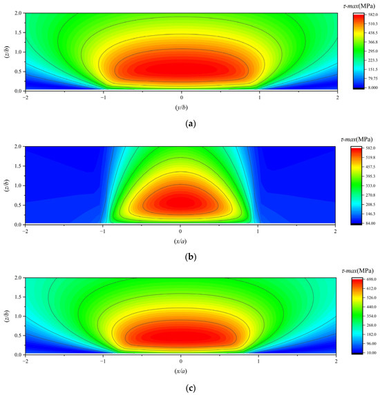
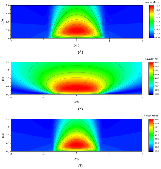
Figure 15.
(a,b) The maximum subsurface shear stress under working condition 4; (c,d) the maximum subsurface shear stress under working condition 5; (e,f) the maximum subsurface shear stress under working condition 6.
To investigate the effect of load on the location of subsurface stress, this paper summarizes the magnitude and location of the maximum subsurface stress values under working conditions 2, 4, 5, and 6 in Table 7, Table 8 and Table 9.
Table 7.
Magnitude and location of the maximum subsurface orthogonal shear stress component τyz under working conditions 2, 4, 5, and 6.
Table 8.
Magnitude and location of the maximum subsurface orthogonal shear stress component τxz under working conditions 2, 4, 5, and 6.
Table 9.
Magnitude and location of the maximum subsurface von Mises stress under working conditions 2, 4, 5, and 6.
In summary, the maximum value of the subsurface von Mises stress is approximately 0.64P0, and the maximum value of the orthogonal shear stress component τyz in the subsurface is approximately 0.25P0.
As the load increases, the subsurface stress intensifies, and the orthogonal shear stress component τyz in the subsurface migrates closer to the contact center, approaching the surface. Although the maximum depths of the orthogonal shear stress components τxz on both sides differ due to traction effects, their horizontal coordinates (X-axis positions) converge toward the central axis while maintaining symmetry about the X-axis, and their vertical coordinates (Y-axis positions) shift closer to the surface. Both the subsurface von Mises stress and the maximum subsurface shear stress exhibit higher concentrations near the surface, with their peak values occurring closer to the surface. Consequently, higher loads induce subsurface stress localization near the surface, increasing the likelihood of fatigue spalling.
5. Discussion
This paper calculates the magnitude of subsurface stress in the bearing raceway with MoS2 coating and its depth position beneath the subsurface. Subsequently, an analytical discussion is conducted on the current work by incorporating the L-P model.
- (1)
- In reference [11], Zheng et al. replicated the subsurface stress field of bearings calculated by Lundberg et al. in reference [1], and the results they obtained were consistent with those in the original study. Additionally, Zheng et al. conducted analyses using practical examples, which further ensured the accuracy of their results. Building upon the method in reference [11], we integrated the actual test curves of MoS2 and superimposed the corresponding stress fields, thereby obtaining more precise results.
- (2)
- Currently, two predominant bearing fatigue life theories exist internationally: the Lundberg-Palmgren (L-P) theory [1] and the Generalized Bearing Life Model (GBLM) [23] developed by SKF.
The L-P theory assumes that fatigue cracks in bearings initiate at weak points beneath the surface of the raceway material. Under the action of subsurface orthogonal shear stress, stress concentration and plastic deformation occur at these weak points, eventually leading to the formation of micro-cracks that propagate toward the surface, culminating in fatigue spalling. The L-P theory describes the contact fatigue of rolling bearings using the following equation:
S is the survival probability of the material after N million stress cycles; N is the number of stress cycles (in millions); τ0 is the maximum orthogonal shear stress; z0 is the depth at which τ0 occurs; V is the stressed volume; and c, e, h are material constants determined experimentally.
In the L-P theory, the failure mode of bearings is attributed to a single subsurface origin. In contrast, the GBLM model proposes that the fatigue failure mechanism of bearings stems from a combined origin of both the subsurface and surface layers. By incorporating the survival probability of the raceway surface into the fundamental rolling contact life equation, they derived a new life equation as follows:
Here, the first half represents the influence of subsurface-originated factors, and the second half pertains to the influence of surface-originated factors.
In both bearing fatigue life theories, subsurface fatigue origin remains the primary source of bearing fatigue failure. From Equation (50), it can be seen that calculating the fatigue life of bearings using the L-P theory is highly complex, as it is related to the density of material defects and requires extensive testing to obtain the relevant exponents. Therefore, fatigue life of bearings cannot be directly determined solely through subsurface stress calculations. Nevertheless, the L-P theory still enables us to analyze the influence of subsurface stress on fatigue life.
As the load increases, the magnitude of these orthogonal shear stresses rises, consequently elevating the probability of raceway fatigue spalling. With higher traction coefficients, when the orthogonal shear stresses become concentrated near the surface, their effective depth diminishes. This reduction in depth shortens the propagation path for cracks to reach the surface, thereby increasing the probability of failure.
Compared with dry friction, the low traction coefficient of MoS2 coating significantly improves the fatigue life of the bearing.
- (3)
- At present, this paper is solely focused on studying the actual impact of coatings on the subsurface stress distribution. Further in-depth research will delve into a detailed exploration of how coating thickness affects subsurface stress. Additionally, experimental research will be carried out on the S-N curves of bearing materials with MoS2 coatings and on the fatigue life of bearings with MoS2 coatings. Given the complexity of such research, these studies have been incorporated into our research plan.
6. Conclusions
This study focuses on the subsurface stress distribution of MoS2 solid lubricated angular contact ball bearings and explores the influence of the traction coefficient and load on their stress distribution. The conclusions are as follows:
- (1)
- The traction coefficient has minimal impact on the stress distribution in the YZ plane and only marginally affects the magnitude of the subsurface von Mises stress. This suggests that sliding friction in the bearing predominantly occurs in the XZ plane, which is perpendicular to the rolling direction.
- (2)
- As the traction coefficient increases, the stress positions on one side of τxz move farther away from the surface, while those on the other side approach closer to it. When the traction coefficient reaches a certain level, the stresses on the side closer to the surface show a tendency to concentrate towards the surface. Simultaneously, the XZ-plane stress of the maximum principal stress along the X-axis (σx) also concentrates towards the surface.
- (3)
- It can be observed that as the distance from the surface increases, the subsurface von Mises stress first increases and then decreases. With an increase in load, the distribution of both the maximum subsurface shear stress and the subsurface von Mises stress in an MoS2 solid-lubricated angular contact ball bearing becomes larger and more concentrated, with their maximum values moving closer to the surface.
- (4)
- The maximum value of the subsurface von Mises stress is approximately 0.64P0, and the maximum value of the orthogonal shear stress component τyz in the subsurface is approximately 0.25P0.
Author Contributions
Conceptualization, B.S. and C.L.; methodology, Z.G.; software, Z.G.; validation, B.S. and C.L.; formal analysis, C.L.; investigation, B.S.; resources, B.S.; data curation, C.L.; writing—original draft preparation, C.L.; writing—review and editing, C.L.; visualization, C.L.; supervision, B.S.; project administration, B.S.; funding acquisition, B.S. All authors have read and agreed to the published version of the manuscript.
Funding
The research is funded by the Horizontal Projects of Henan University of Science and Technology (Horizontal 20220109).
Data Availability Statement
The data used to support the findings of this study are available from the corresponding author upon request.
Conflicts of Interest
Author Zeyu Gong is employed by the Luoyang Bearing Research Institute Co., Ltd. The remaining authors declare that the research was conducted in the absence of any commercial or financial relationships that could be construed as potential conflicts of interest.
References
- Lundberg, G.; Palmgren, A. Dynamic Capacity of Rolling Bearings. J. Appl. Mech. 1949, 16, 165–172. [Google Scholar]
- Miyashita, Y.; Yoshimura, Y.; Xu, J. Subsurface Crack Propagation in Rolling Contact Fatigue of Sintered Alloy. JSME Int. J. Ser. A Solid Mech. Mater. Eng. 2003, 46, 341–347. [Google Scholar] [CrossRef][Green Version]
- Qin, F.; Sun, L.; Xie, Y. Research on the Approach for the Assessment of Subsurface Rolling Contact Fatigue Damage. Appl. Mech. Mater. 2013, 2659, 845–851. [Google Scholar] [CrossRef]
- Mizozoe, S.; Katsuyuki, K. Internal Shear Stress Distribution and Subsurface Cracks of PPS Thrust Bearings under Rolling Contact Fatigue in Water. Key Eng. Mater. 2020, 858, 101–105. [Google Scholar] [CrossRef]
- Greco, A.; Martini, A.; Liu, Y. Rolling Contact Fatigue Performance of Vibro-Mechanical Textured Surfaces. Tribol. Trans. 2010, 53, 610–620. [Google Scholar] [CrossRef]
- Yan-long, L.; Qiong, W.; Xiao-feng, Q.; Chang-sheng, L. Contact Fatigue Damage and Subsurface Microstruture of Cr5 Backup Roll. J. Northeast. Univ. 2020, 41, 818–823. [Google Scholar]
- Hanwei, F.; Shaotian, Z. Rolling contact fatigue modelling and life prediction for aeroengine bearing steels. J. Aeronaut. Mater. 2024, 44, 129–138. [Google Scholar]
- Peng, B. Researches on Surface Damage of High-Speed Sliding/Rolling Contact Tribo-Parts in Aircraft Engines. Ph.D. Thesis, Harbin Institute of Technology, Harbin, China, 2012. [Google Scholar]
- Wang, W.; Cheng, J.; Hong, R. Influence of Friction Coefficient on Contact Subsurface of Single-Row Ball Slewing Bearings. Bearing 2018, 9, 44–48. Available online: https://link.cnki.net/doi/10.19533/j.issn1000-3762.2018.09.012 (accessed on 28 July 2025).
- Yang, W.; Yao, Q.; Yu, J. Research on Elastic Composite Cylindrical Roller Bearing Contact Fatigue Based on the Subsurface Stress. Int. J. Rotating Mach. 2023, 2023, 7622545. [Google Scholar] [CrossRef]
- Zheng, X.; Du, S.; Zhang, Y. Calculation of Stress Field in Rolling-Slip Contact of Rolling Bearings Based on Matlab. Lubr. Eng. 2020, 45, 52–61. [Google Scholar] [CrossRef]
- Kadiric, A.; Sayles, R.S.; Zhou, X.B.; Ioannides, E. A Numerical Study of the Contact Mechanics and Sub-Surface Stress Effects Experienced Over a Range of Machined Surface Coatings in Rough Surface Contacts. J. Tribol. 2003, 125, 720–730. [Google Scholar] [CrossRef]
- Onodera, T.; Morita, Y.; Nagumo, R. A Computational Chemistry Study on Friction of h-MoS2 Part II Friction Anisotropy. J. Phys. Chem. B 2010, 114, 15832–15838. [Google Scholar] [CrossRef]
- Mutyala, K.C.; Singh, H.; Fouts, J.A.; Evans, R.D.; Doll, G.L. Influence of MoS2 on the Rolling Contact Performance of Bearing Steels in Boundary Lubrication: A Different Approach. Tribol. Lett. 2016, 61, 20. [Google Scholar] [CrossRef]
- Singh, N.; Sinha, K.S. Tribological Studies of Epoxy Composites with UHMWPE and MoS2 Fillers Coated on Bearing Steel: Dry Interface and Grease Lubrication. J. Tribol. 2020, 142, 051902–051910. [Google Scholar] [CrossRef]
- Li, B.; Liu, X.; Zhang, J.; Liu, B.; Lu, Z. Surface Dimples Composite MoS2 Nickel-based Coating and Its Friction and Wear Properties. Surf. Tech. 2022, 51, 215–225. [Google Scholar] [CrossRef]
- Singh, N.; Sinha, K.S. Tribological performances of polymeric plain bearings made of epoxy matrix with UHMWPE, MoS2, Kevlar and base oil as the fillers. Part J J. Eng. Tribol. 2025, 239, 363–374. [Google Scholar] [CrossRef]
- Zhang, K.; Deng, J.; Lei, S.; Yu, X. Effect of micro/nano-textures and burnished MoS2 addition on the tribological properties of PVD TiAlN coatings against AISI 316 stainless steel. Surf. Coat. Tech. 2016, 291, 382–395. [Google Scholar] [CrossRef]
- Hills, D.; Nowell, D.; Sackfield, A. Mechanics of Elastic Contacts, 1st ed.; Elsevier: Amsterdam, The Netherlands, 1993; pp. 291–319. [Google Scholar]
- Gupta, P.K. Traction coefficients for some solid lubricants for rolling bearing dynamics modeling. Tribol. Trans. 2000, 43, 647–652. [Google Scholar] [CrossRef]
- Niu, R.; Han, Z.; Wang, Y.; Li, H.; Deng, S. Wear life analysis of angular contact ball bearing in high temperature environment. J. Aerosp. Power 2022, 37, 1780–1792. [Google Scholar] [CrossRef]
- Su, B.; Li, H.; Zhang, G.; Liu, F.; Cui, Y. Study on Cage Stability of Solid-Lubricated Angular Contact Ball Bearings in an Ultra-Low Temperature Environment. Lubricants 2024, 12, 124. [Google Scholar] [CrossRef]
- Antonio, G.; Morales-Espejel, G.E. A model for hybrid bearing life with surface and subsurface survival. Wear 2019, 422–423, 223–234. [Google Scholar] [CrossRef]


Disclaimer/Publisher’s Note: The statements, opinions and data contained in all publications are solely those of the individual author(s) and contributor(s) and not of MDPI and/or the editor(s). MDPI and/or the editor(s) disclaim responsibility for any injury to people or property resulting from any ideas, methods, instructions or products referred to in the content. |
© 2025 by the authors. Licensee MDPI, Basel, Switzerland. This article is an open access article distributed under the terms and conditions of the Creative Commons Attribution (CC BY) license (https://creativecommons.org/licenses/by/4.0/).