Abstract
The lateral vibration of propulsion shafting is a critical factor affecting the acoustic stealth performance of underwater vehicles. As the main vibration isolation component in transmitting vibrational energy, the damping efficiency of the propulsion shafting support system (PSSS) holds particular significance. This study investigates the dynamic characteristics of the PSSS with the integral squeeze film damper (ISFD). A dynamic model of ISFD–PSSS is developed to systematically analyze the effects of shaft speed and external load on its dynamic behavior. Three test bearings (conventional, 1S, and 3S structure) are designed and manufactured to study the influence of damping structure layout scheme, damping fluid viscosity, unbalanced load, and shaft speed on the vibration reduction ability of ISFD–PSSS through axis orbit and vibration velocity. The results show that the damping effects of ISFD–PSSS are observed across all test conditions, presenting distinct nonlinear patterns. Suppression effectiveness is more pronounced in the vertical direction compared to the horizontal direction. The 3S structure bearing has better vibration reduction and structural stability than other schemes. The research results provide a reference for the vibration control method of rotating machinery.
1. Introduction
In marine propulsion systems, shafting vibration-induced structural fatigue and degradation of acoustic stealth performance have emerged as critical challenges constraining equipment reliability [1,2]. Intense vibration energy not only accelerates wear mechanisms in propulsion support systems [3] but may also induce hull resonance through shaft transmission pathways [4], posing severe threats to operational stealth and navigational safety. As the core power transmission component in naval vessels, developing vibration control technologies for propulsion shafting systems holds significant engineering value [5,6].
Squeeze film damper (SFD) technology demonstrates remarkable advantages in mitigating rotor system vibrations and isolating low-frequency propeller excitations through its unique viscous damping mechanism [7,8]. During the operation of the rotor system, the precession motion of the journal will squeeze the SFD structure, prompting the internal lubricating oil to flow along the gap. This process generates a squeeze-damping effect that dissipates vibration energy and attenuates the mechanical vibration of the rotor system. Extensive research has been conducted by scholars on the vibration-attenuation characteristics of SFD in rotating machinery [9,10,11,12,13]. Pan et al. [14] developed a dynamic model for rotor systems with SFD, incorporating nonlinear bearing forces, SFD effects, gravity, and coupling misalignment-induced loads. Results showed that oil film parameters are crucial to system stability. Furthermore, Gupta et al. [15] investigated the effects of SFD process parameters on the radial and circumferential vibration characteristics of rotor systems at high speeds, revealing that supply oil pressure is a critical factor influencing bearing amplitude. Additionally, Golek et al. [16] accounted for thermal effects to establish a thermohydrodynamic SFD bearing model and constructed a specialized experimental setup for validation, demonstrating great vibration-damping performance.
However, when the squeeze film damper experiences large static eccentricity, or the rotor system faces excessive load and unbalanced vibration, the stiffness of the oil film will rise sharply. At this time, the rotor is prone to lock, bistability, non-coordinated vibration, and other nonlinear vibration phenomena, which limits the scope of its operational range and application. To address this issue, researchers have proposed solutions such as elastic ring squeeze film damper (ERSFD) [17], floating ring squeeze film damper (FRSFD) [18] and integral squeeze film damper (ISFD) [8,19,20]. Among these, the ERSFD and the FRSFD alter the internal structure of the bearing and affect the load-bearing capacity of supporting bearings, rendering them unsuitable for use in propulsion shafting systems. The ISFD is typically positioned on the bearing’s outer lining, enhancing the rotor system’s vibration-damping performance while maintaining the load-bearing capacity of the bearing’s inner lining.
Based on the type of damping structure, ISFD can be divided into S-type ISFD [21], C-type ISFD [22], G-type ISFD [23], and so on. The S-type ISFD can effectively suppress the circumferential flow of oil film and enhance the damping effect, which has attracted widespread attention from researchers. Kumar et al. [24] verified the reliability of S-type ISFD in rotor systems by combining finite element simulations and tests for low-cycle fatigue and high-cycle fatigue to predict the fatigue life of the S-type ISFD. Zhang et al. [20] analyzed the stability and vibration characteristics of a single-sided cantilever rotor system containing an ISFD structure based on a FEM model. The simulation results showed that the arranged scheme of ISFD had different effects on the stability, energy distribution, and vibration control of the rotor system. Yan et al. [25] experimentally found that the S-type ISFD structure can effectively reduce the sensitivity of the rotor to unbalance and suppress the resonance of the rotor at critical speed. Therefore, the S-type ISFD structure has been employed by many researchers in different fields. Zhu et al. [26] conducted experimental research on gear transmission systems, pointing out that the ISFD has good vibration suppression capabilities for gears at different speeds, with a horizontal vibration reduction of 75.44% and a vertical vibration reduction of 68.48%. Ertas et al. [27] applied ISFD to a 46 MW steam turbine to address sub-synchronous vibration induced by fluid excitation in the rotor. This intervention enhances the stability of the rotor system, enabling the unit to operate safely and stably at full capacity. The existing research has generated valuable insights, yet investigations into the application of ISFD to PSSS remain limited. Specifically, the interaction mechanism between ISFD and the dynamic characteristics of support systems under propeller-induced unbalanced excitation and the influence of damping fluid viscosity requires further exploration.
This paper establishes a dynamic model of ISFD–PSSS to analyze the influence of rotational speed and external load on its dynamic behavior. An experimental test rig for the rotor system is established to investigate the influence of rotational speed, damping fluid viscosity, damper structure configuration, and unbalanced load on the vibration-attenuation capability of three test bearings. The organization of this paper is arranged as follows: Section 2 introduces the structure scheme of the test bearings and analyzes their load capacity. Section 3 presents the dynamic characteristics modeling method and analysis of ISFD–PSSS. Section 4 conducted vibration characteristic tests on ISFD–PSSS. Finally, conclusions are given in Section 5.
2. Structure and Static Stiffness Simulation of ISFD–PSSS
This Section details three test bearing structural schemes and design rationales, evaluates their static performance to determine stiffness coefficients, and supplies critical input parameters for the bearing system’s dynamic model.
2.1. Structure Scheme
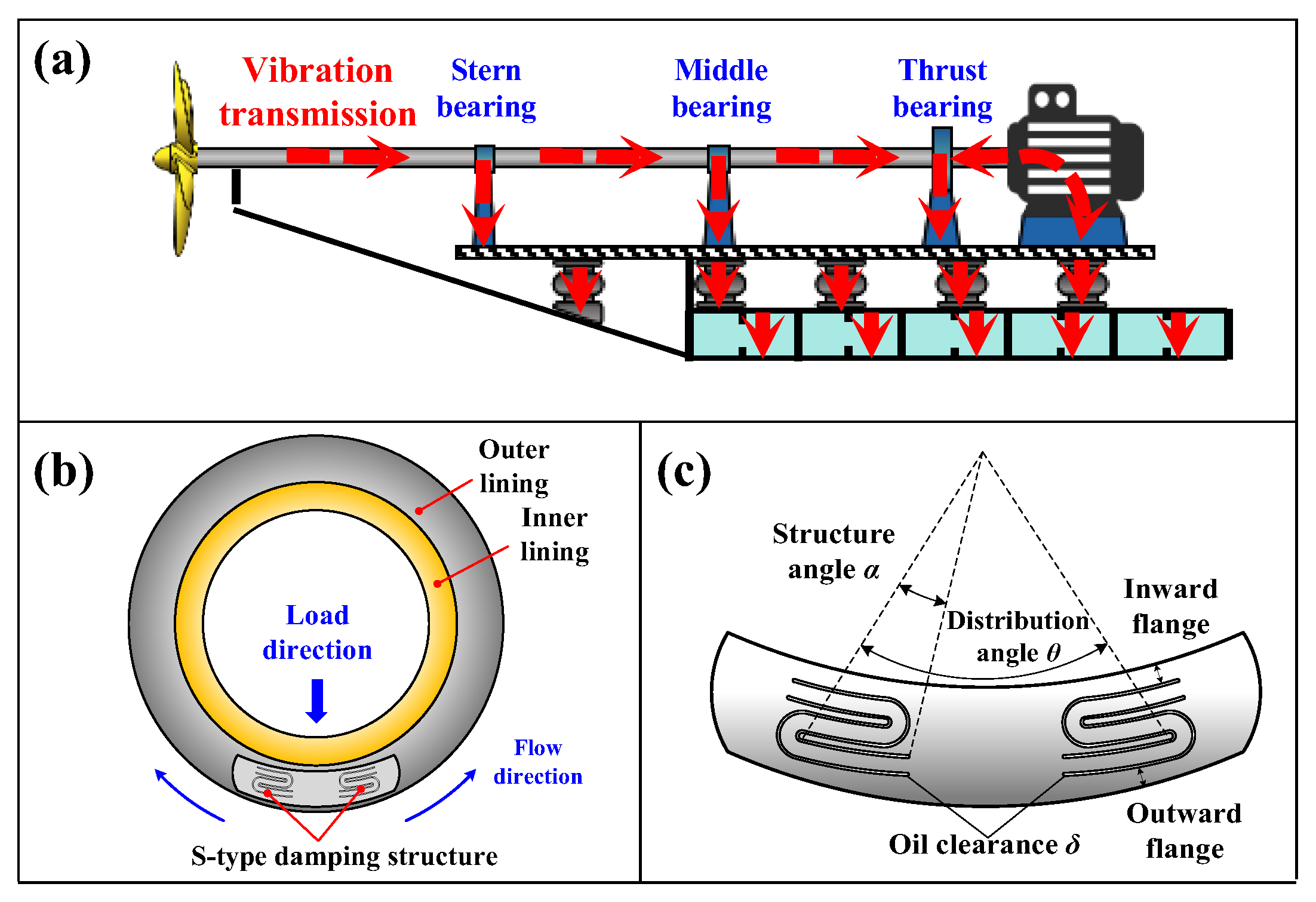
This study aims to enhance the vibration-damping performance of middle bearings of PSSS, as shown in Figure 1a, while preserving their load-bearing capacity, and to investigate the dynamic characteristics of the composite system. Journal bearings are commonly employed as middle bearings in propulsion shafting, typically comprising an inner lining and an outer lining, as shown in Figure 1b, which are assembled by interference fit or vulcanized to ensure no relative sliding between them. Compared to the outer lining, the wear resistance and stiffness of the inner lining exert a more pronounced influence on the load-bearing capacity of the journal bearing. To mitigate adverse effects on bearing performance, the S-type damping structure is integrated into the outer lining, and damping fluid is injected into the annular gap. Its operational principle is detailed as follows: During the operation of the propulsion shafting, as the journal rotates and processes within the bearing hole, periodic excitation forces acting on the outer lining will cause elastic deformation of the ISFD structure, driving upward flow of the damping fluid within the annular gap. Due to the non-uniform deformation of the S-shaped elastic structure and fluid viscosity-induced resistance, the damping fluid forms localized high-pressure zones as it passes through narrow gaps. The energy dissipation occurring within these high-pressure zones converts vibration energy into thermal energy, thereby achieving vibration attenuation. Therefore, the geometric parameters of the S-shaped curve (Figure 1c), such as the oil film gap δ, height of inward flange h, distribution angle θ, and structural angle α, significantly influence the structure’s squeeze damping effect, which serves as a critical determinant of the system’s vibration attenuation capability.

Figure 1.
Structure of ISFD–PSSS: (a) Vibration transmission path of propulsion shafting; (b) Design scheme of ISFD–PSSS; (c) Damping structure.
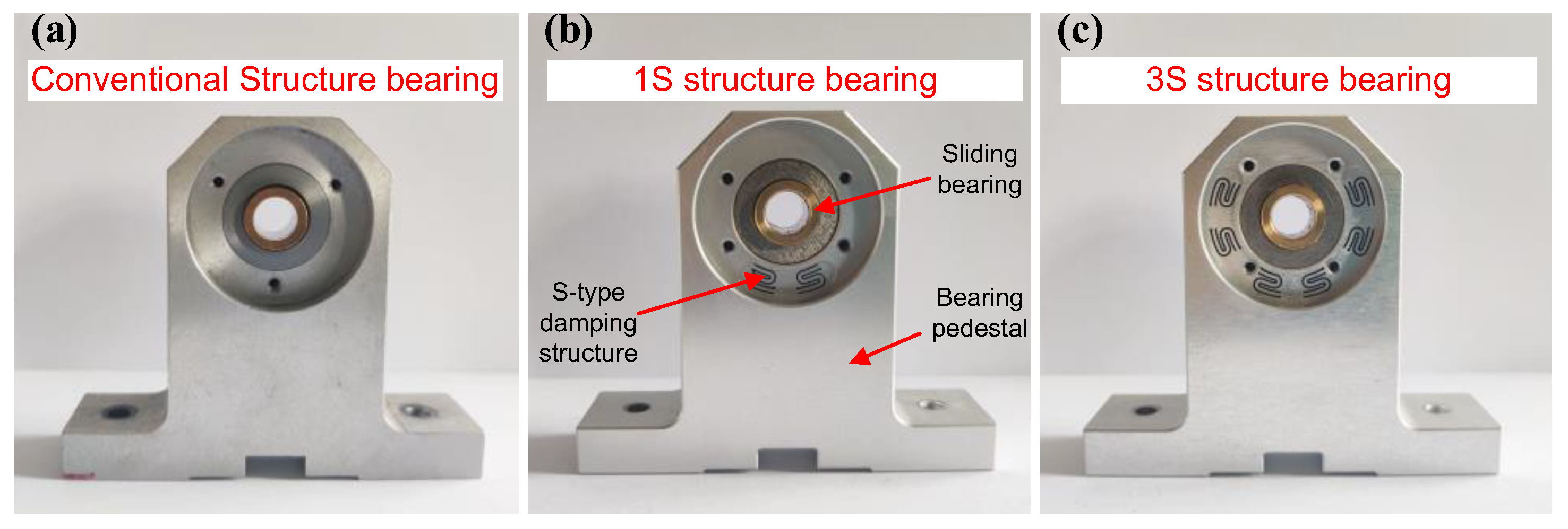
The middle bearing of the propulsion shafting is classified as the oil-lubricated journal bearing. To facilitate subsequent research, we accordingly designed three scaled oil-lubricated journal bearings: conventional journal bearing (CJB), 1S structure journal bearing (1S-JB), and 3S structure journal bearing (3S-JB), as shown in Figure 2. The CJB refers to journal bearings that do not include ISFD, which was used as a control group to analyze the vibration reduction ability of the 1S-JB and 3S-JB. Additionally, the rationale for selecting the 1S and 3S configurations lies in analyzing the suppression effect of the test bearing with ISFD damper on horizontal and vertical vibrations induced by gyroscopic effects and shaft misalignment. This selection also determines the number of S-shaped structures: one set is positioned at the bottom to address vertical vibration, while three sets are required to suppress both vertical and horizontal vibrations.

Figure 2.
Three types of bearing structures: (a) CJB (b) 1S-JB (c) 3S-JB.
The test bearings were copper oil-lubricated sliding bearings fixed on the outer lining through the transition sleeve. The use of conventional machining methods for ISFD structures confronts two major limitations: First, the difficulty of completing deep hole drilling or complex surface machining arises from tool geometry constraints (minimum curvature radius greater than 0.5 mm). Second, during processing, the stress induced by cutting forces frequently causes deformation in thin-walled structures (thickness < 2 mm) [28], which often fails to meet design specifications. It should be noted that to achieve a better squeeze damping effect, the S-shaped channels are close to each other, which leads to the formation of a thin-walled structure in the middle part. The non-contact electrical discharge machining (EDM) technology [29] employed in this study leverages its non-mechanical energy dissipation mechanism to eliminate macroscopic mechanical forces during processing. This characteristic not only mitigates deformation in thin-walled geometries but also ensures dimensional precision (±2 μm) for intricate structures with complex geometries.
Notably, the curvature parameters of the S-shaped structure were designed based on the results of the team’s previous research [30]. Regarding the selection of the structural angle, to avoid compromising the bearing’s load-bearing capacity, the S-shaped structure cannot be arranged directly beneath the bearing. Considering that the bearing undergoes an attitude angle of 5~20° during operation, and its primary load-bearing region is concentrated within 20~30° at the bottom of the bearing [31], a structural angle of 16° was selected. Additionally, the test bearings maintain identical geometries except for their damping structure configurations. The structural parameters of these three bearing types are summarized in Table 1 and subsequent simulations will refer to this parameter.

Table 1.
Structural parameters of the test bearing.
2.2. Static Stiffness Simulation
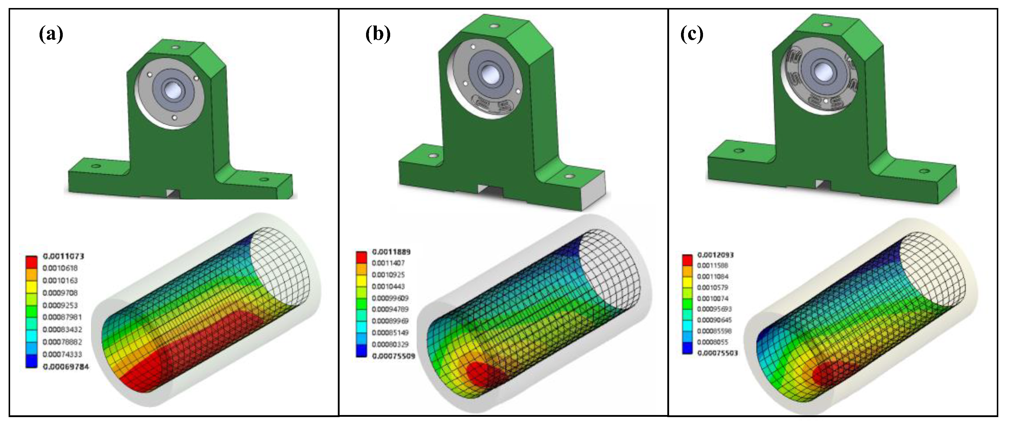
Stiffness reflects a system’s resistance to deformation under load, which can be influenced by damping structures. The ISFD design removes material from the outer lining, potentially reducing load-bearing capacity. Therefore, we perform finite element analysis on the test bearings to calculate static stiffness and assess the damping structure’s impact. This work regulated the external load by varying the density of the shaft material. Specifically, the load application direction aligns with the gravitational force direction. The load was applied at the contact interface between the shaft and the bearing, and a frictional contact was set on this interface. The fixed constraint was imposed at the bottom of the bearing housing to simulate the middle bearing being fixed on the base during service. The load ranges from 0 to 2000 N, with increments of 200 N per step. By calculating the displacement of the inner lining under different loads, the static stiffness of the bearing can be obtained, which can be substituted into the dynamic characteristic model in Section 3 for the calculation of the comprehensive stiffness of the oil film and the bearing with the ISFD structure. According to the deformation cloud of the test bearings under 400 N, as shown in Figure 3, it can be found that concentrated deformation areas are in 1S-JB and 3S-JB, with maximum deformation values similar to CJB. The average deformation of the inner lining surface under different loads is used to obtain the bearing stiffness. The calculation formula for bearing stiffness is presented as follows:
where k is the stiffness value; F is the applied load; S is the deformation.

Figure 3.
Deformation cloud of bearing at 400 N: (a) CJB; (b) 1S-JB; (c) 3S-JB.
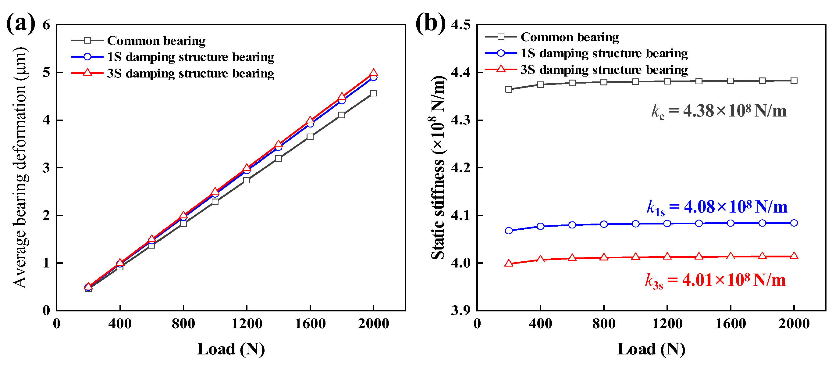
Figure 4 shows that the average displacement of the bearing inner surface increases linearly with the increase in the applied load. It can be found that the S-type structure will affect the load capacity of the test bearing to a certain extent. However, both 1S-JB and 3S-JB displayed only 6.81% and 8.42% reductions in static stiffness compared to the control group CJB, respectively, while their static stiffness values remained at the same order of magnitude. The simulation results of reference [32] showed that the stiffness variation of the middle bearing has no significant effect on the transverse vibration of the shaft within one order of magnitude. Therefore, this work takes it as the criterion for judging the bearing capacity. The static stiffness coefficients of 1S-JB and 3S-JB maintain the same order of magnitude as CJB, so the reduction in stiffness will not exacerbate the transverse vibration of the bearing and meet the load design requirement that the bearings equipped with ISFD structures have comparable load-bearing capacities to CJB.

Figure 4.
Results of stiffness calculation: (a) Variation of the average displacement of the bearing inner surface with load; (b) Variation of bearing static stiffness with load.
3. Dynamic Characteristics of ISFD–PSSS
This Section presents the comprehensive dynamic model of the ISFD–PSSS system, including the calculation methods for lubricating oil film and ISFD structural dynamic coefficients, and analyzes rotational speed effects on integrated stiffness and damping coefficients.
3.1. Modeling Method
3.1.1. Comprehensive Dynamic Characteristics of ISFD–PSSS
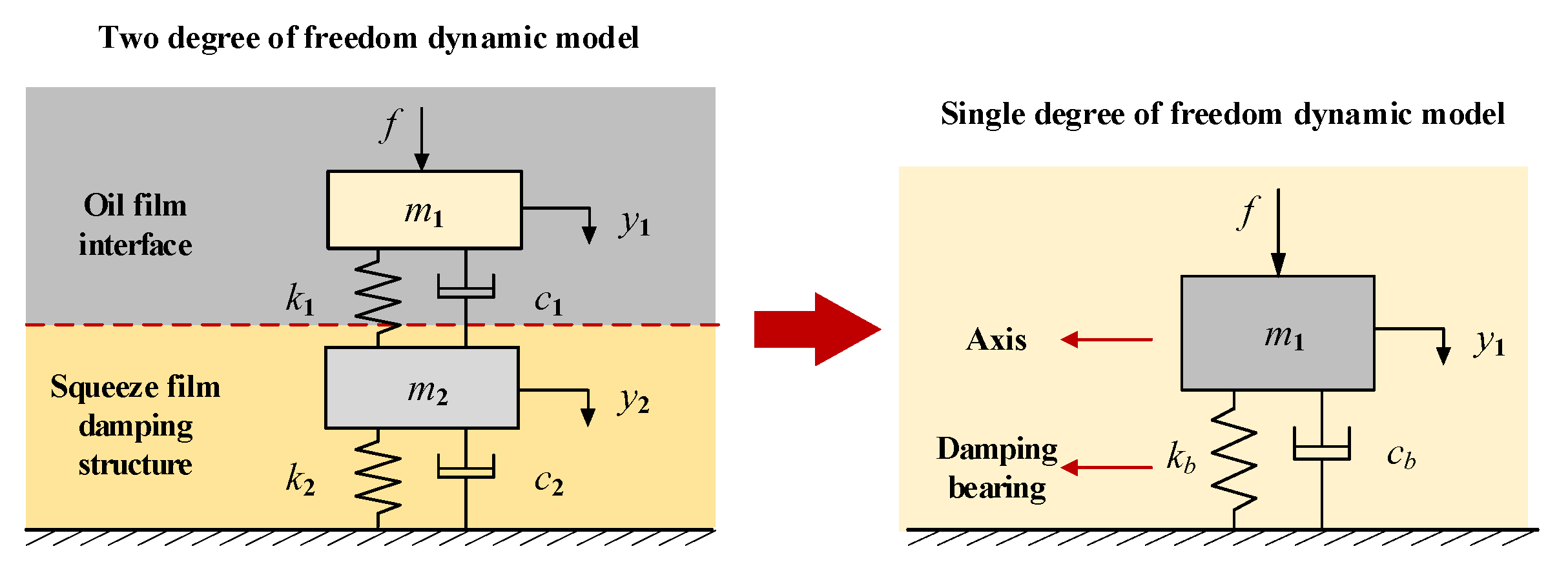
The ISFD–PSSS can be equivalent to a two-degree-of-freedom spring mass system. Its comprehensive dynamic characteristics can be obtained by combining the dynamic characteristics of the lubricant film and the damping bearing, as shown in Figure 5. f is the external excitation force, k1 and c1 are the stiffness and damping coefficients of the lubricant film, respectively, derived from the vertical main stiffness kyy and damping coefficient cyy of the bearing liquid film. The specific calculation method is elaborated in Section 3.1.2. m1, m2 are the masses of the shaft and damping bearing, respectively. The stiffness and damping coefficients of the bearing equipped with the ISFD damper are k2 and c2. Given that the stiffness of the damping fluid within the damping structure is almost negligible compared to the structural stiffness, k2 is defined as the static stiffness of the damping bearing structure, which is derived from the data presented in Figure 4.
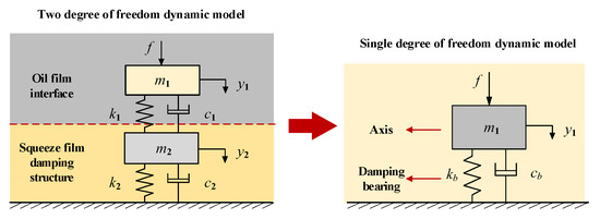
Figure 5.
Simplification process of damping bearing dynamic model.
The comprehensive dynamic characteristic model of the rotor system is as follows:
The above equation is a two-degree-of-freedom system, and Equation (3) is the steady-state response under harmonic excitation.
where ω is the excitation force frequency, φ1 and φ2 are the corresponding phase angles.
The bearing displacement response is obtained by solving the matrix equation.
The equivalent dynamic characteristic model of a single-degree-of-freedom bearing is shown as Equation (6).
Fourier change the above equation.
The dynamic characteristic coefficients are identified using the displacement impedance method. The displacement impedance function Z and phase difference φ are as follows:
Combining Equations (4), (7) and (8), the comprehensive dynamic characteristics coefficients of the rotor system are obtained as:
where kb is the comprehensive bearing stiffness, cb is the comprehensive bearing damping, φ is the phase difference between the excitation force and the displacement response.
3.1.2. Dynamic Characteristics of Lubricant Film
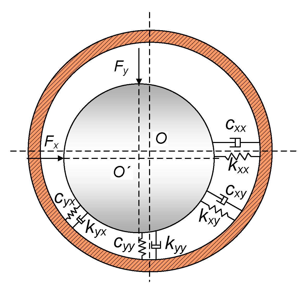
The linearized eight stiffness-damping coefficients are usually used to characterize the dynamic performance of the bearing lubricant film, which are four stiffness coefficients (horizontal main stiffness, vertical main stiffness, cross stiffness) and four damping coefficients (horizontal main damping, vertical main damping, cross damping), as shown in Figure 6.
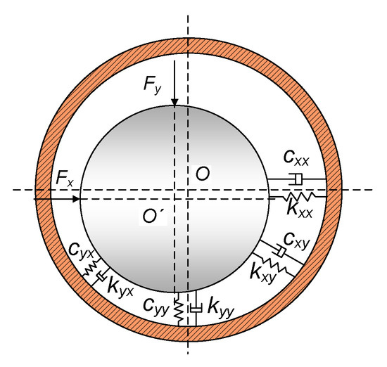
Figure 6.
The diagram of bearing lubricant film stiffness-damping coefficients.
The dynamic characteristic coefficient of the lubricant film is expressed in Equation (10) when the bearing is displaced by external loads during stable operation.
where ΔFx is the horizontal variation lubricant film force, ΔFy is the vertical variation oil film force.
The stiffness and damping coefficients of the lubricating oil film are solved via partial differentiation. The formulation in Equation (11) incorporates film pressure p derived from our established bearing elastohydrodynamic lubrication model [33].
where L is the axial length of the bearing, p is the film pressure, ϕa and ϕb are the film boundary conditions, θ is the circumferential coordinate of the column coordinate system, z is the axial coordinate.
3.1.3. Dynamic Characteristics of ISFD Structure
The S-type damper can be modeled as the superposition of multiple single-layer plates, with their extrusion model illustrated in Figure 7. Note that Figure 7 employs a local coordinate system where the z, x, and y denote the vertical, horizontal, and axial directions of the bearing, respectively. For the remainder of the paper, these directions are defined relative to the y, x, and z, respectively. The clearance in the extrusion model is 2h, with plate length 2a and width 2b; the relative velocity between plates is v0, and oil flow velocities along the x and z directions in the clearance are vx and vz (no flow along the y direction); the lubricant pressure is p, ambient pressure is Pa (set to zero in this simulation). In addition, the masses of the shaft and the damping bearing are m1 and m2, respectively.
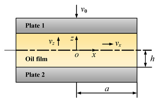
Figure 7.
Schematic diagram of the extrusion model.
The dynamic model of the S-type damper mainly consists of three parts: the constitutive equation, control equation, and definite solution condition. The basic expression of Newton’s constitutive equation of oil film is as follows:
where τxz is the shear stress; η0 is the lubricant viscosity.
The control equation is mainly composed of the continuity equation and the motion equation. The fluid velocity conforms to the control equation under the premise of neglecting the fluid inertia force and mass force. The continuity equation and motion equation are shown in Equations (13) and (14).
The momentum equation in fluid mechanics needs definite solution conditions to solve, corresponding to the boundary conditions in the model. The Navier boundary slip condition is used to analyze the boundary slip velocity as shown in Equation (15).
where β is the slip coefficient. When β is 0 it means no slip; when β tends to infinity it means full lubrication.
The damping force equation of the integral squeeze film damping structure is obtained by solving the above model. The result is as follows:
The damping coefficient of the single-layer oil film of the damping structure is obtained by differentiating the velocity. The result is shown as follows:
3.2. Dynamic Characteristics Simulation Analysis of ISFD–PSSS
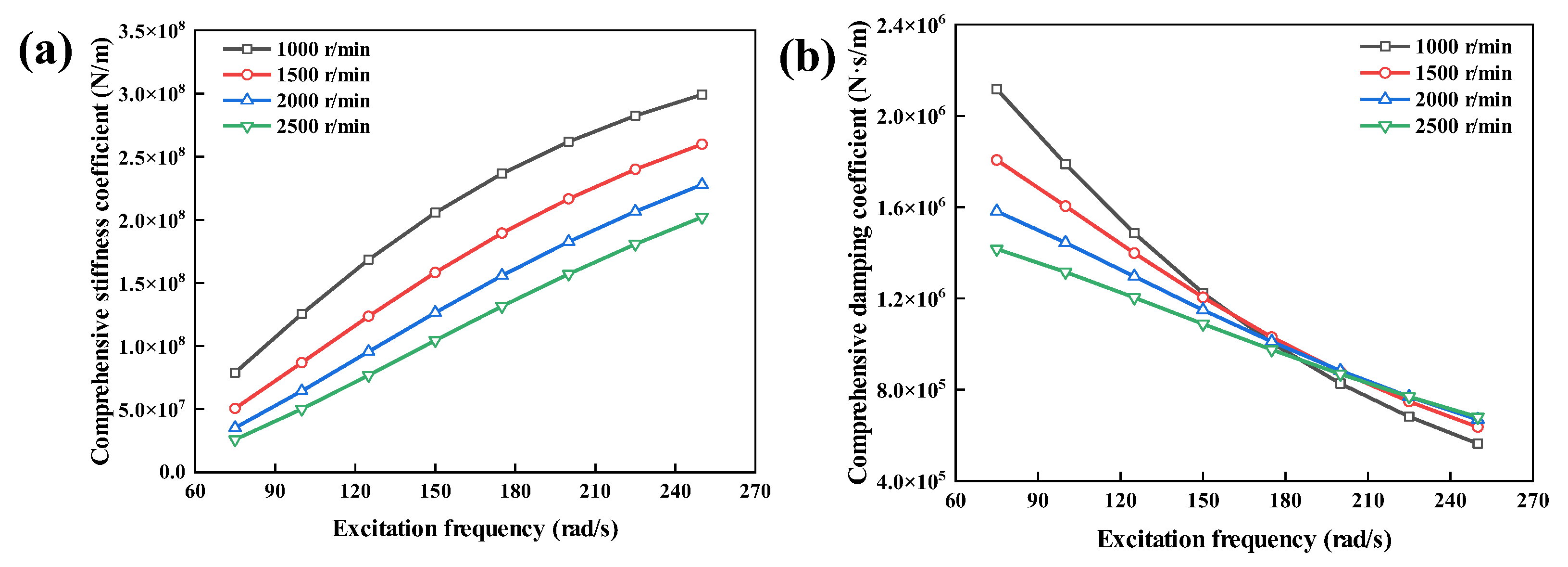
The structural parameters employed in this section are listed in Table 1, while the working condition parameters are defined based on the test conditions outlined in Section 4. Figure 8 shows the variation of comprehensive stiffness and damping coefficients of ISFD–PSSS under different rotational speeds and excitation frequencies. With the increase in excitation frequency, the comprehensive stiffness coefficient increases, and the comprehensive damping coefficient decreases. The effect of excitation frequency on the dynamic characteristic of the ISFD–PSSS is more significant at low speeds. This phenomenon may result from two factors: First, the mass of the ISFD–PSSS amplifies structural inertia effects at higher excitation frequencies, especially when the mass term (ω2 M) boosts overall stiffness. Second, while the system’s damping effect originates from the damping fluid’s shear and flow energy dissipation, excessive excitation frequencies shorten the fluid film’s movement cycle. This restricts fluid flow through the S-shaped damping structure, reducing energy absorption efficiency and lowering the system’s effective damping capacity.

Figure 8.
Variation of comprehensive dynamic characteristic coefficients of ISFD–PSSS with speed and excitation frequency: (a) Comprehensive stiffness coefficient; (b) Comprehensive damping coefficient.
Regarding the impact of rotational speed, the comprehensive stiffness and damping coefficients exhibit decreasing trends with the rotational speed increase, which is attributed to the journal lift-up effect induced by speed increase, reducing the bearing eccentricity ratio. Such reduction consequently diminishes both the stiffness and damping coefficient of the lubricating film, thereby coupling with the system’s comprehensive dynamic characteristics. Moreover, the damping effect at high speed is greater than that at low speed after the excitation frequency is greater than about 160 rad/s.
4. Vibration Characteristics Test of ISFD–PSSS
This Section utilizes a shafting vibration characteristic test rig to conduct performance tests on three test bearings under variable rotational speeds and lubricant viscosities. Vibration velocities of the bearings and displacements of the counterweight disc are measured to assess their vibration attenuation performance.
4.1. Test Rig and Bearings
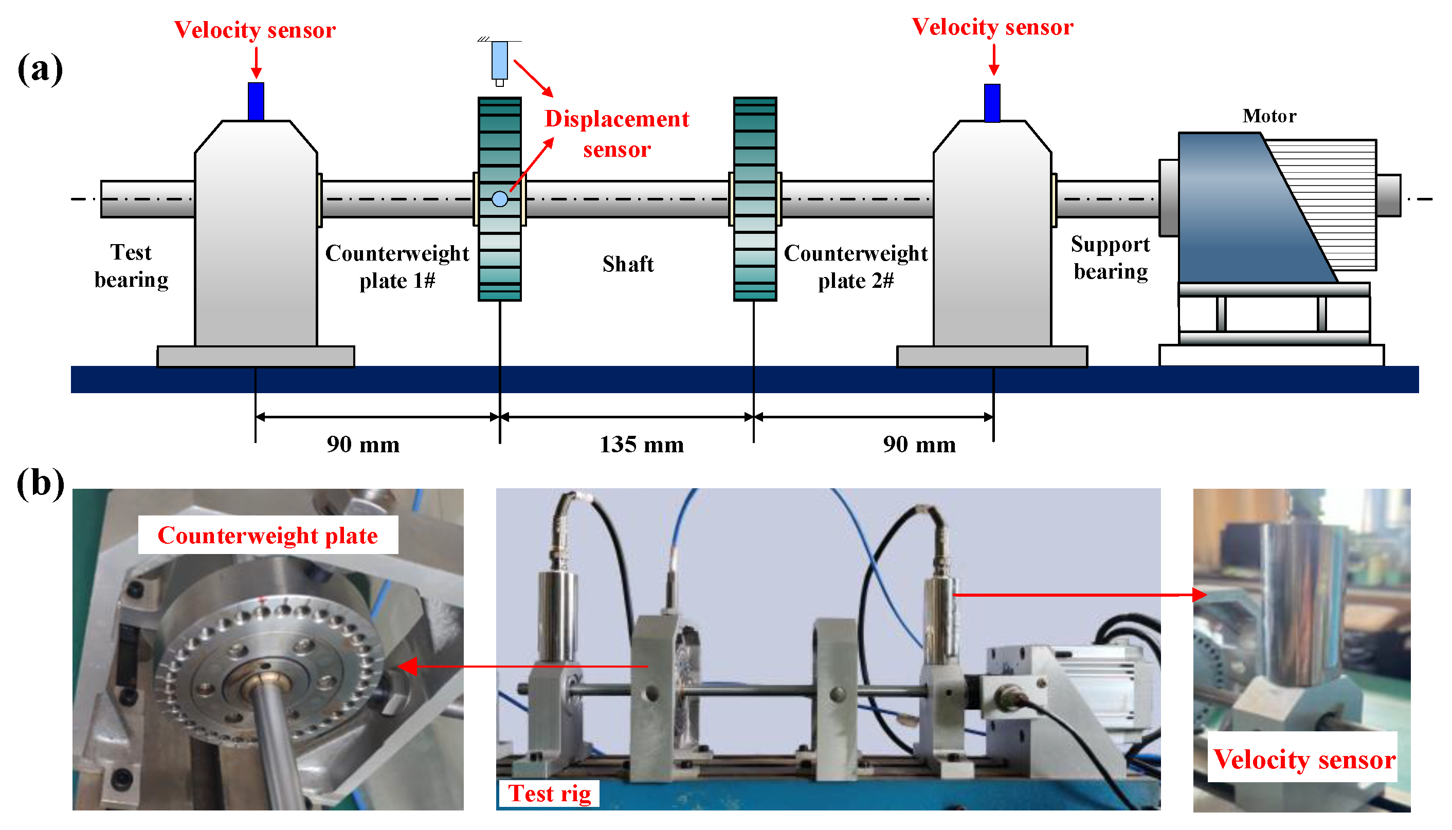
During the service period, the PSSSs are inevitably subjected to unbalanced loads generated from shaft misalignment and the propeller, which constitutes one of the main factors contributing to lateral vibration in propulsion shafting. Accordingly, this study employs a rotor system vibration characteristics test rig (Figure 9a) to analyze the vibration suppression capabilities of the CJB, 1S-JB, and 3S-JB. The test bearing was installed in the bearing pedestal, fixed with the base by a T-shaped slider. The damping effect of the 1S-JB and 3S-JB was adjusted by changing the viscosity of the damping fluid.
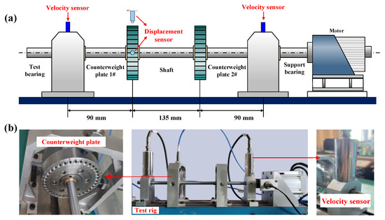
Figure 9.
Test rig: (a) Schematic diagram; (b) Physical diagram.
The drive part of the test rig was driven by a DC parallel-excited motor with a rated current of 2.5 A and an output power of 250 W. The stepless speed regulation of the motor can be realized by manually adjusting the output voltage of the regulator. The test bearing was installed at the end of the test rig. The inner diameter of the test bearing is 10 mm, and the bearing length is 25 mm. Two counterweight plates were installed on the rotating shaft, and unbalanced bolts were installed on counterweight plate #1 to provide an unbalanced load. The size of the counterweight plate was Φ76 × 19 mm, and the mass was 600 g.
In terms of testing system layout, the vibration velocity sensor was installed above the test bearing, with a sampling frequency of 4096 Hz and an FFT resolution of 0.16 Hz. The vibration suppression capability of the ISFD structure is evaluated by analyzing the line spectrum peaks in the spectrum. Two eddy current displacement sensors have been installed on the vertical and horizontal directions of the counterweight plate #1 to obtain its axis orbit, and their sampling frequency is consistent with the former.
Table 2 shows the test conditions. The CJB was used as the control group. The PMX-200 (synthetic oil) damping fluids with consistent quality but varying viscosity were selected. The damping fluid with viscosity of 500 cst and 1000 cst was filled to 1S-JB and 3S-JB in turn, and the comparative analysis was carried out under the working condition without damping fluid (0 cst). The choice of high-viscosity lubricating oil in this study stems from the operational conditions of the PSSS. These bearings operate under low-speed, heavy-load conditions with significant low-frequency vibrations. By opting for a higher-viscosity lubricant, we aim to enhance the stiffness of the oil film, mitigate damping failure arising from excessive extrusion, and strengthen the damping force generated by the squeeze film damper under a low-frequency scenario, and ultimately improve its low-frequency vibration suppression capability.
Table 2.
Test condition settings.
The adjusted test conditions include rotational speed and unbalanced mass. The test speed range was 500~3000 r/min, with each 500 r/min as a test group. Four bolt configurations (0, 1, 3, and 5 unbalanced bolts) were implemented on counterweight plate #1 to create varying levels of imbalance, as illustrated in Figure 9b. The corresponding unbalanced masses for the three operational conditions were 3 g, 9 g, and 15 g. The vibration response of the test bearing and the axis orbit of counterweight #1 were measured and recorded.
4.2. Results and Discussion
4.2.1. The Effect of Damping Structure on Vibration
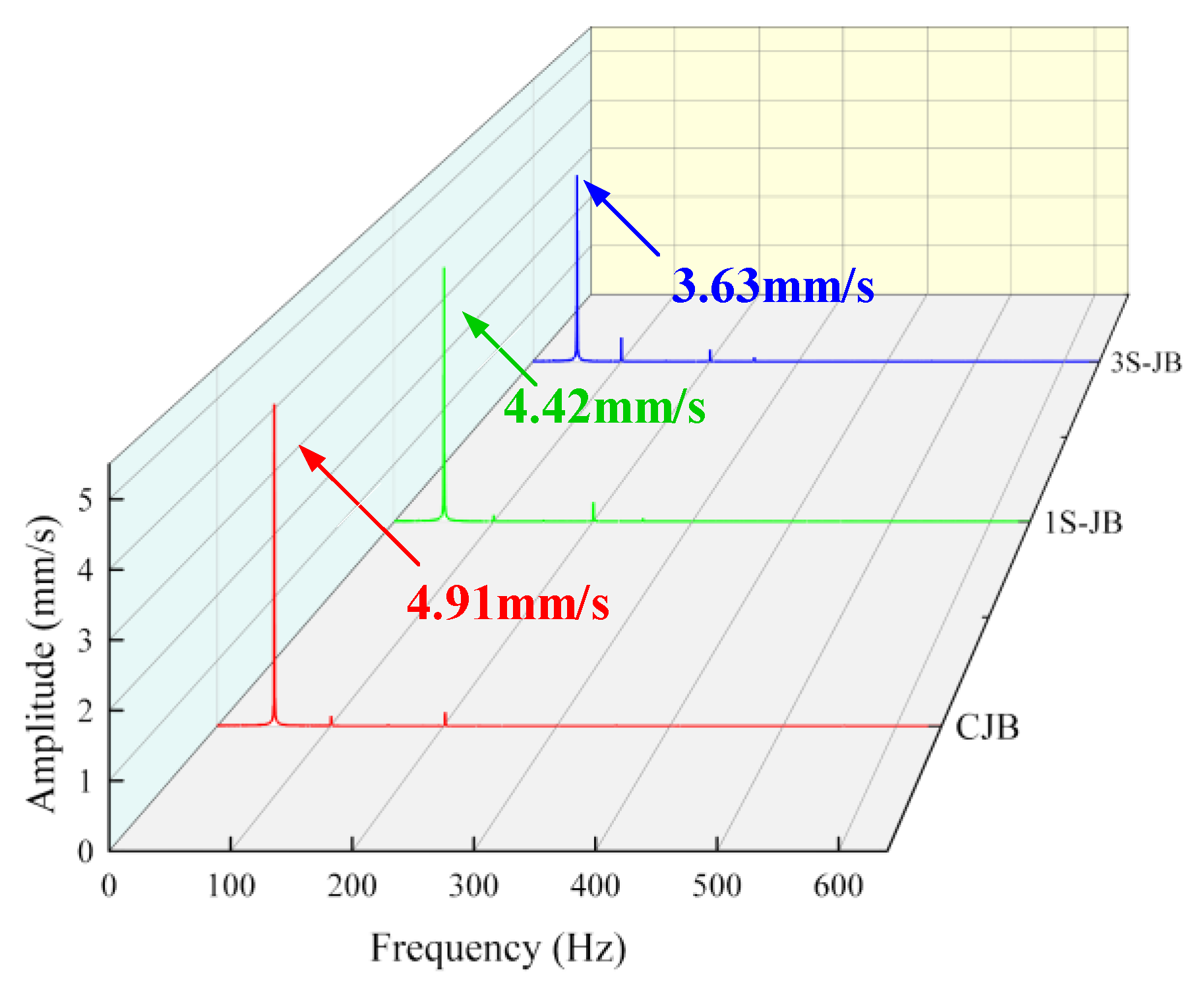
Figure 10 shows the vibration frequency spectrum of the test bearings under 3000 r/min and 500 cst of damping fluid. It can be observed that the damping structure does not affect the spectral characteristics of the rotor system. The frequency corresponding to the highest spectrum peak of 1S-JB and 3S-JB bearings is similar to that of CJB, but the amplitude is lower than that of CJB, and the amplitude of 3S-JB is the lowest, indicating that the vibration-attenuation performance is the best under this working condition.
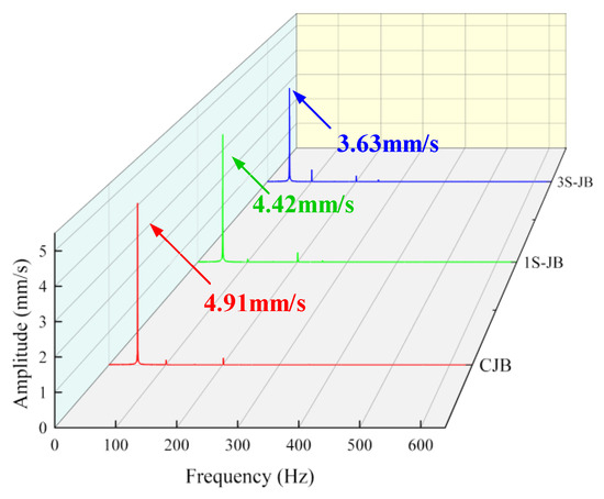
Figure 10.
Comparison of vibration frequency spectrum of the test bearings.
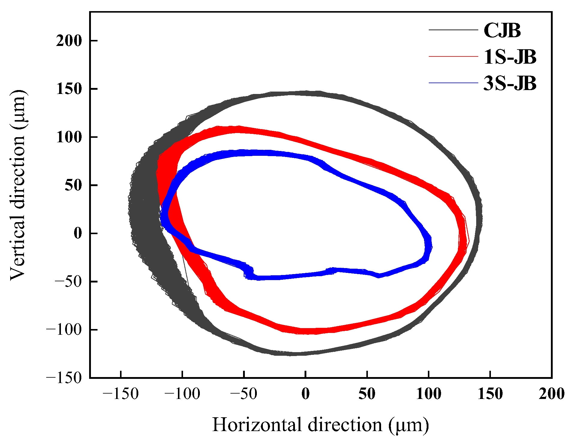
Figure 11 depicts the axis orbit of the counterweight plate under different test bearings. Compared with the CJB, both 1S-JB and 3S-JB demonstrate reduced size of the axis orbit of the counterweight plate. The horizontal displacement amplitude is reduced by 11.6% and 23.2%, while the vertical displacement amplitude is reduced by 21.4% and 50.7%, respectively. The 3S bearing exhibits superior vibration suppression performance in both directions, with particularly enhanced damping effectiveness in the horizontal orientation due to the arrangement scheme of the S-type damper.

Figure 11.
The axis orbit of the counterweight plate when different test bearings were installed.
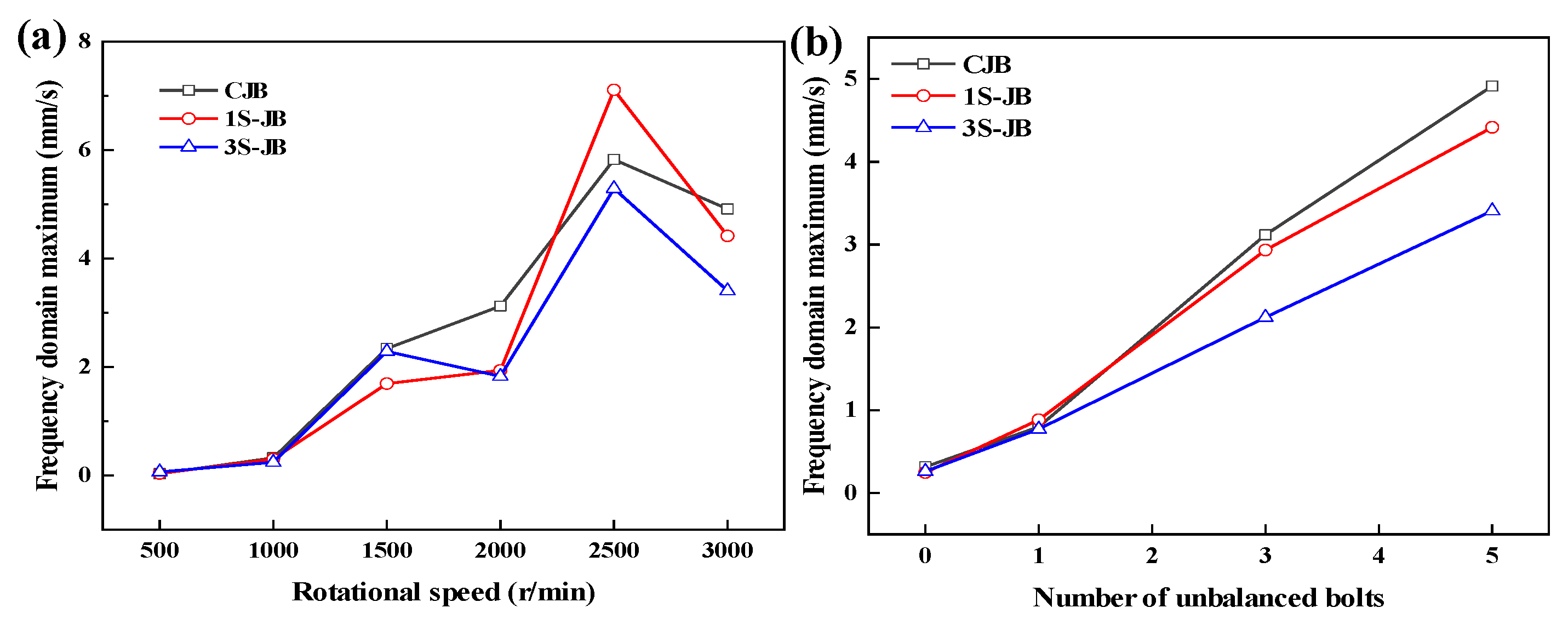
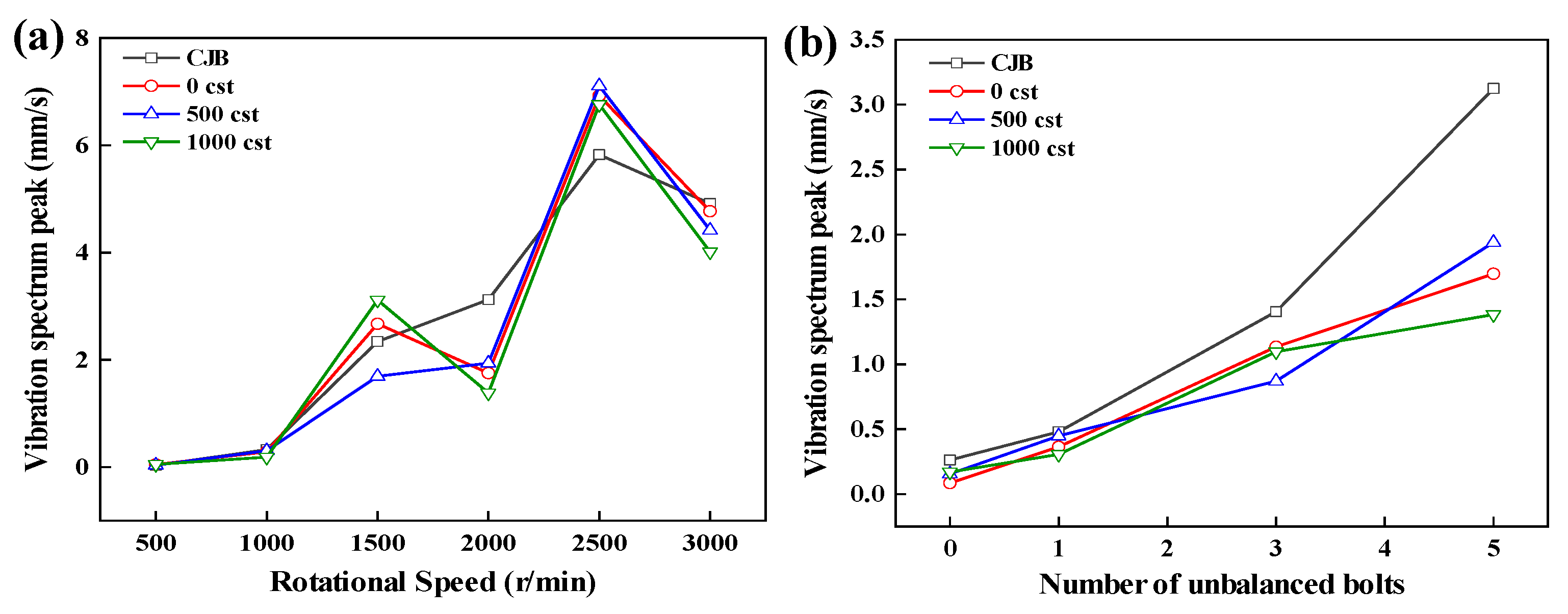
Figure 12a presents the influence of rotational speed on the maximum values of the frequency spectrum of the test bearing. It can be observed that all test bearings exhibit similar vibration trends across varying speeds. The 1S-JB and 3S-JB demonstrate substantial vibration-attenuation across multiple operational speeds, with peak reductions of 37.9% (1S-JB) and 41.4% (3S-JB). The vibration surges at 2500 r/min, while the 1S-JB amplitude is greater than the CJB due to the resonance of the test bearing pedestal at that speed. Figure 12b shows the influence of an unbalanced load on the maximum values of the frequency spectrum of the test bearing. With the increase in unbalanced load, the amplitude peaks increased as expected, while the ISFD structure is able to provide continuous vibration-attenuation, with maximum peak vibration reduction ratios of 21.6% and 31.9% for the 1S and 3S bearings, respectively. Furthermore, the vibration reduction performance of the ISFD structure is enhanced with increasing unbalanced load, and its efficacy in reducing the journal’s motion amplitude aligns with findings from the prior literature [8]. This correlation corroborates the reliability of the results to a certain extent.

Figure 12.
The maximum values of the frequency spectrum when different test bearings were installed: (a) Rotational speed; (b) Unbalanced mass.
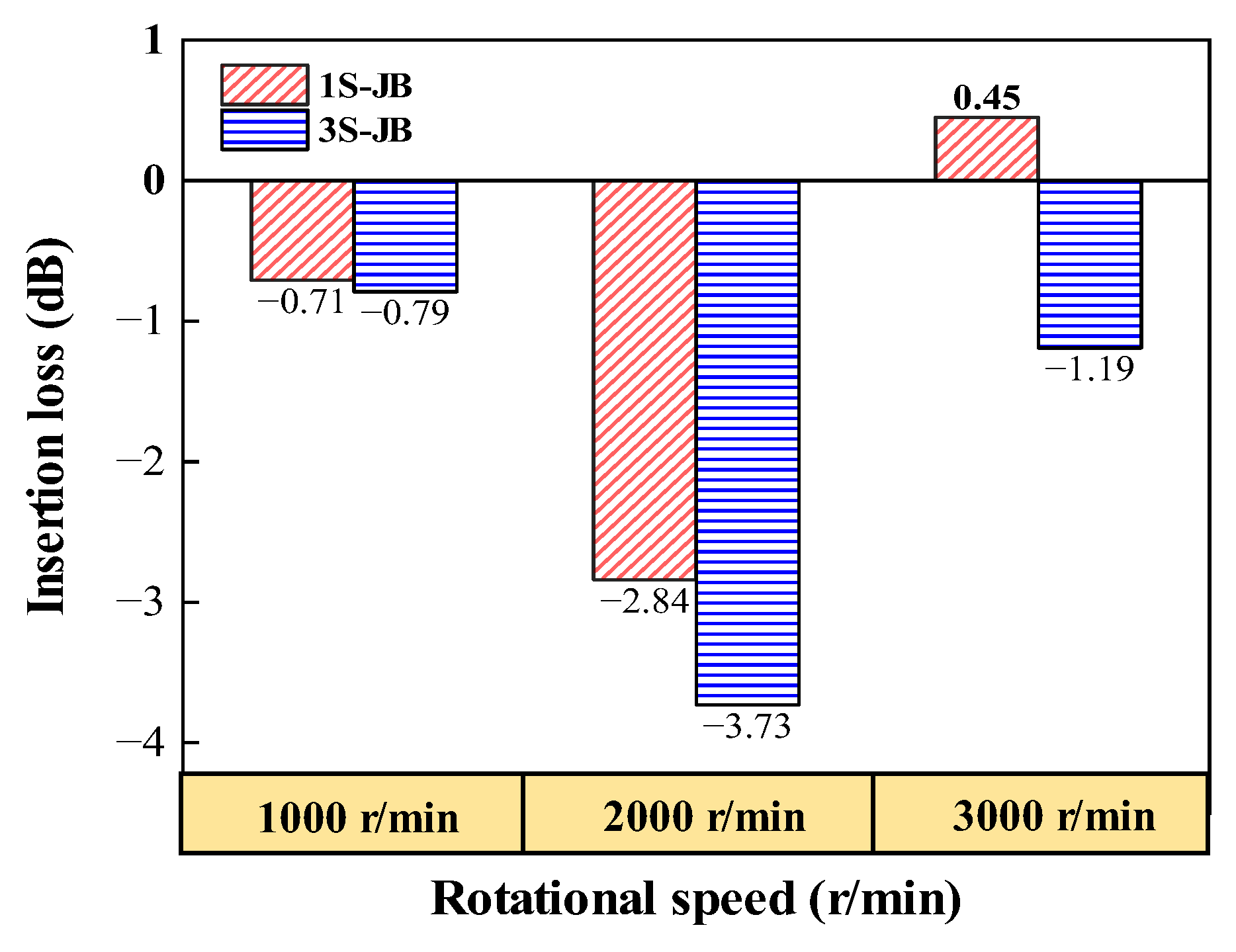
The insertion loss is introduced to quantitatively analyze the vibration-attenuation ability of test bearings, as shown in Figure 13. The insertion loss of the 1S-JB and 3S-JB at 2000 r/min is significantly greater than that at the rest speeds, with a maximum is 3.73 dB, indicating that the damping structure has significant vibration reduction at this speed. The insertion loss of 1S-JB is negative at 3000 r/min; the reason is that the 1S-JB increases the disturbance under this condition, which makes the total vibration level increase. In summary, the damping structure has better vibration reduction between 1000 r/min and 2000 r/min.

Figure 13.
The insertion loss of the total vibration level of the 1S-JB and 3S-JB under different speeds.
4.2.2. The Effect of Damping Fluid Viscosity on Vibration
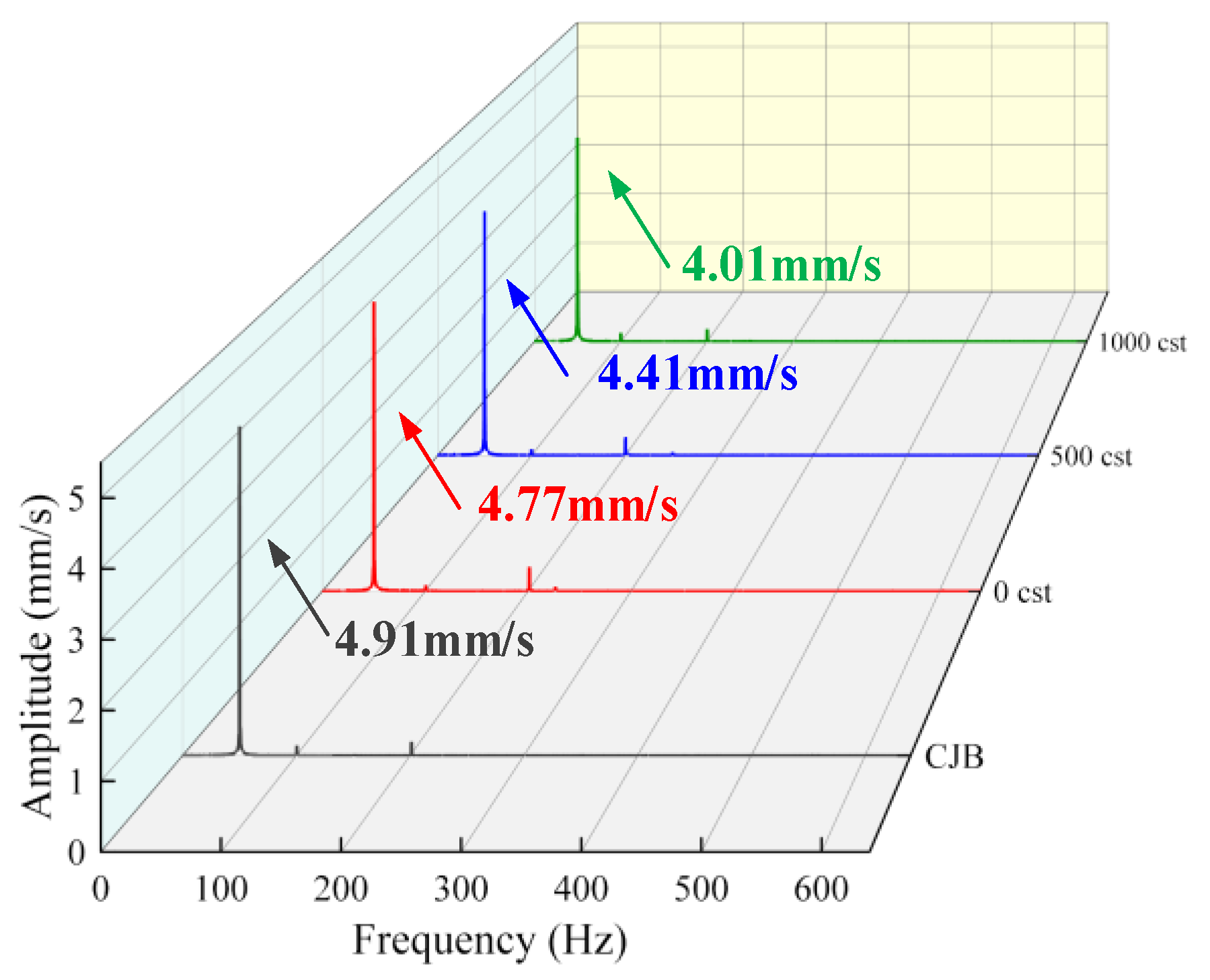
In this Section, CJB and 1S-JB are selected to further explore the influence of damping fluid viscosity on bearing vibration characteristics. Figure 14 demonstrates the comparison of the vibration frequency spectrum of the test bearings filled with different viscosity damping fluid under 3000 r/min and an unbalanced load of 15 g, where 0 cst condition means the damping structure is not filled. The spectral peaks of the 1S-JB at different viscosities are 4.77, 4.41, and 4.01, respectively, and the peak reduction ratios are 3.46%, 10.75%, and 18.84% compared with that of the CJB, indicating that the increase in the viscosity of the damping fluid can enhance the vibration damping capability of the ISFD structure under the working condition.
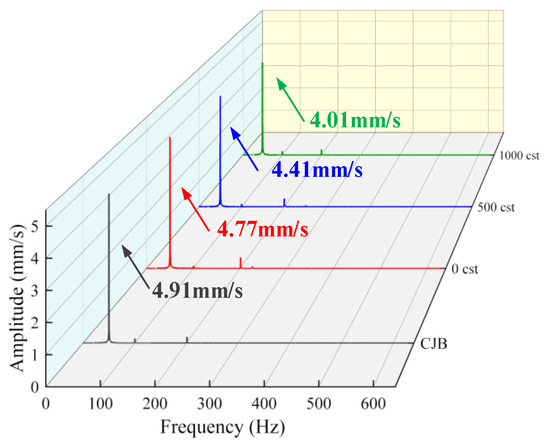
Figure 14.
Comparison of the vibration frequency spectrum of the CJB and 1S-JB with different viscosity damping fluids.
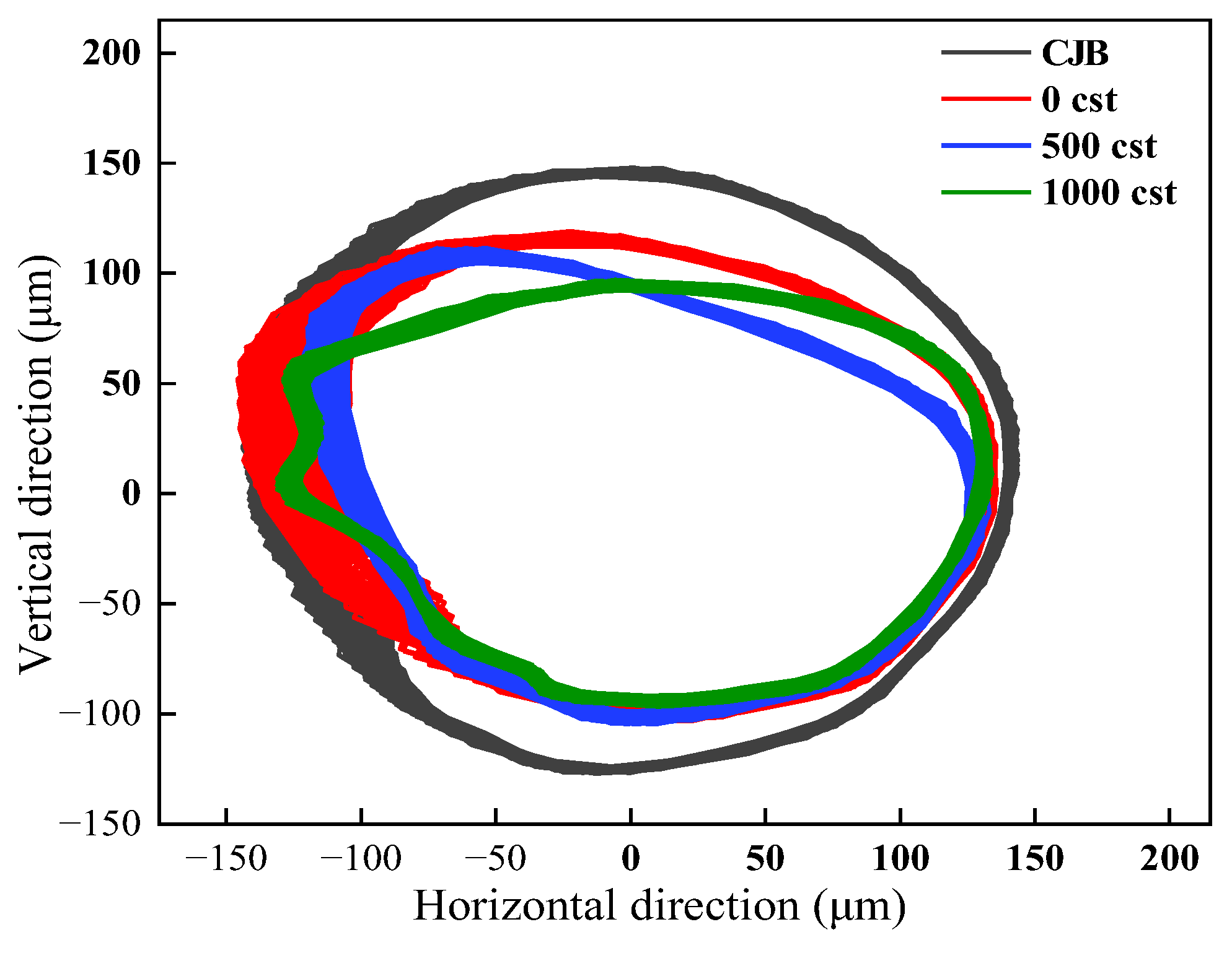
Figure 15 depicts the axis orbit of the counterweight plate under different damping fluid viscosities. Compared with CJB, the 1S-JB exhibits reduction ratios of 2.1%, 11.6%, and 7.8% in the horizontal direction, and 18.9%, 21.4%, and 29.6% in the vertical direction when utilizing damping fluid viscosities of 0, 500, and 1000 cst, respectively. These findings demonstrate that increasing damping fluid viscosity exhibits minimal impact on horizontal vibration-attenuation performance, whereas vertical vibration suppression shows substantial enhancement correlated with viscosity increase.

Figure 15.
The axis orbit comparison of the counterweight plate under different damping fluid viscosities.
Figure 16a presents the maximum values of the frequency spectrum under different viscosities of damping fluid and speed. The vibration suppression capability of the 1S-JB at 500 cst damping fluid viscosity is more stable than the other two viscosities. The vibration-attenuation is better at 1000, 2000, and 3000 r/min. Compared to CJB, the maximum vibration reduction ratio of the damping bearing is 21.6%, 37.9%, and 55.7% at 0, 500, and 1000 cst damping fluid viscosity, respectively. As shown in Figure 16b, the maximum values of the frequency spectrum of 1S-JB under each unbalanced load are lower than those of CJB. The maximum vibration reduction ratio of 1S-JB under three kinds of viscosity is 67.3%, 40.7%, and 55.7%, respectively. The results show that the change of unbalanced load will not affect the effect of increasing the viscosity of the damping fluid on the improvement of vibration reduction ability.

Figure 16.
The maximum values of the frequency spectrum under different viscosities of the damping fluid: (a) Rotational speed; (b) Unbalanced load.
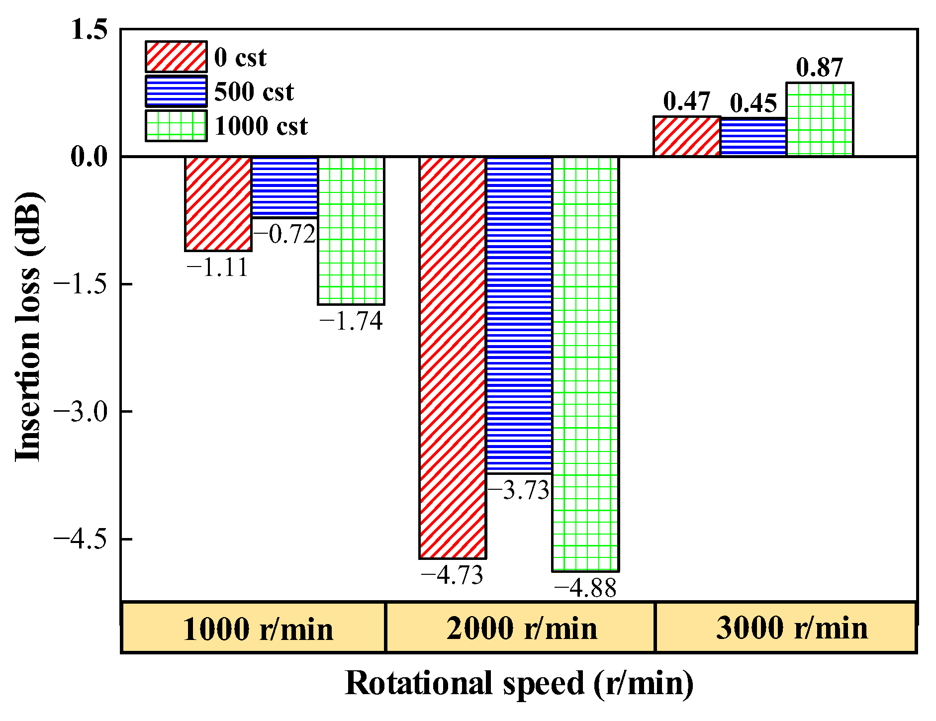
Figure 17 demonstrates the insertion loss of the total vibration level of the 1S-JB under different damping fluid viscosities. The increase in damping fluid viscosity exerts a nonlinear influence on the vibration suppression effectiveness of the 1S-JB across different rotational speeds. Specifically, the 1S-JB demonstrates optimal damping performance at 2000 r/min, achieving a maximum insertion loss of 4.88 dB. However, at 3000 r/min, the damping structure amplifies the vibration amplitude. This phenomenon may stem from excessive rotational speed intensifying the inertial forces of the oil film, which induces cavitation within the damping structure. Such cavitation triggers a sharp decline in the system damping coefficient, thereby exacerbating vibrations. In general, the damping effect of the 1S-JB fluctuates greatly with the change of viscosity. Therefore, different from the theoretical calculation, the large viscosity of the damping fluid cannot be pursued in practical application. It is necessary to balance the relationship between viscosity and operating conditions to achieve the optimal results of vibration-attenuation.

Figure 17.
The insertion loss of the total vibration level of the 1S-JB under different damping fluid viscosities.
5. Conclusions
In this paper, the dynamical model of ISFD–PSSS is proposed to analyze the relationships between working conditions and dynamic characteristics. Three bearing structures are designed to explore the vibration suppression ability of the ISFD. The following conclusions are obtained:
- (1)
- The ISFD structures exhibit a relatively small impact on static stiffness, with 1S-JB and 3S-JB demonstrating similar load-bearing capacities. The comprehensive stiffness coefficient increases proportionally with rising excitation frequencies, while the comprehensive damping coefficient exhibits an inverse correlation.
- (2)
- The ISFD structure effectively suppresses lateral vibrations induced by rotor imbalance, exhibiting superior attenuation in the vertical direction. Comparative analysis reveals that the 3S-JB achieves better vibration reduction in spectral amplitude and axis orbits compared to the 1S-JB.
- (3)
- Damping fluid viscosity significantly influences the vibration characteristics of the 1S-JB and 3S-JB through nonlinear damping–viscosity interactions. Therefore, it is suggested that the damping fluid viscosity should be reasonably selected considering the operating conditions of the ISFD–PSSS.
Author Contributions
Conceptualization, W.O. and G.X.; methodology, W.O. and Q.L.; validation, G.W.; formal analysis, Q.L.; investigation, G.W. and Q.L.; resources, W.O., G.W. and G.X.; data curation, Q.L., W.O., G.X. and G.W.; writing—original draft, Q.L.; writing—review and editing, Q.L. and G.W.; supervision, W.O. and G.W.; project administration, W.O. All authors have read and agreed to the published version of the manuscript.
Funding
This research is supported by the grants from the National Key R&D Program of China (No: 2023YFB3405900).
Data Availability Statement
The data presented in this study are available on request from the corresponding author.
Conflicts of Interest
Author Gaohui Xiao was employed by Shanghai Turbine Works Company Ltd. The remaining authors declare that the research was conducted in the absence of any commercial or financial relationships that could be construed as a potential conflict of interest.
Abbreviations
The following abbreviations are used in this manuscript:
| ISFD | Integral squeeze film damping |
| PSSS | propulsion shafting support system |
| SFD | Squeeze film damper |
| ERSFD | Elastic ring squeeze film damper |
| FRSFD | Floating ring squeeze film damper |
| EDM | Electrical Discharge Machining |
| CJB | Conventional journal bearing |
| 1S-JB | One S-type structure journal bearing |
| 3S-JB | Three S-type structure journal bearing |
References
- Duan, N.; Wu, C.; Huang, Y.; Zhang, Z.; Hua, H. Lateral vibration analysis and active control of the propeller-shafting system using a scaled experimental model. Ocean Eng. 2023, 267, 113285. [Google Scholar] [CrossRef]
- Tuninetti, V.; Martínez, D.; Narayan, S.; Menacer, B.; Oñate, A. Design Optimization of a Marine Propeller Shaft for Enhanced Fatigue Life: An Integrated Computational Approach. J. Mar. Sci. Eng. 2024, 12, 2227. [Google Scholar] [CrossRef]
- Jiao, C.; Yang, Y.; Zhang, X.; Xue, L.; Zou, D.; Xu, J.; Ta, N.; Rao, Z. Mixed lubrication characteristics of multi-layer composite structure water-lubricated stern bearing considering fluid–structure interaction and journal misalignment effects. Phys. Fluids 2025, 37, 053601. [Google Scholar] [CrossRef]
- Gu, Z.; Liu, J. Multidisciplinary Design Optimization of Alignment and Whirling Vibration Characteristics of a Submarine Propulsion Shafting Using Kriging Surrogate Model. J. Mar. Sci. Eng. 2024, 12, 1812. [Google Scholar] [CrossRef]
- Zou, D.; Liu, G.; Rao, Z.; Tan, T.; Zhang, W.; Liao, W.-H. A device capable of customizing nonlinear forces for vibration energy harvesting, vibration isolation, and nonlinear energy sink. Mech. Syst. Signal Process. 2021, 147, 107101. [Google Scholar] [CrossRef]
- Sharma, S.K.; Sharma, R.C.; Upadhyay, R.K.; Lee, J. Coupled torsional–transverse vibration reduction in marine propulsion dynamics with novel approach using magnetorheological damping and adaptive control system. J. Vib. Eng. Technol. 2024, 12, 6089–6099. [Google Scholar] [CrossRef]
- Yan, W.; Lu, J.; Pan, J.; Liu, J.; Fuyang, C.; Ye, D. Research on dynamic characteristic coefficients of integral squeeze film damper. Machines 2024, 12, 274. [Google Scholar] [CrossRef]
- Dong, H.; He, L.; Jia, X. Using integral squeeze film damper to suppress vibration of gas turbine. J. Vib. Eng. Technol. 2023, 11, 3163–3176. [Google Scholar] [CrossRef]
- Gheller, E.; Chatterton, S.; Vania, A. Squeeze film damper modeling: A comprehensive approach. Machines 2022, 10, 781. [Google Scholar] [CrossRef]
- Zheng, W.; Pei, S.; Zhang, Q.; Hong, J. Experimental and theoretical results of the performance of controllable clearance squeeze film damper on reducing the critical amplitude. Tribol. Int. 2022, 166, 107155. [Google Scholar] [CrossRef]
- Zhou, H.; Cao, G.; Chen, X.; Zhang, Y.; Cang, Y. A study on the thermal properties of oil-film viscosity in squeeze film dampers. Lubricants 2023, 11, 163. [Google Scholar] [CrossRef]
- Shi, M.; Yang, Y.; Deng, W.; Wang, J.; Fu, C. Analysis of dynamic characteristics of small-scale and low-stiffness ring squeeze film damper-rotor system. Appl. Sci. 2022, 12, 7167. [Google Scholar] [CrossRef]
- Tian, Z.; Hu, Z.; Tang, J.; Chen, S.; Kong, X.; Wang, Z.; Zhang, J.; Ding, H. Dynamical modeling and experimental validation for squeeze film damper in bevel gears. Mech. Syst. Signal Process. 2023, 193, 110262. [Google Scholar] [CrossRef]
- Pan, W.; Hao, J.; Li, H.; Wang, J.; Bao, J.; Zeng, X.; Nie, P. Dynamic modeling and response analysis of misaligned rotor system with squeeze film dampers under maneuver loads. Nonlinear Dyn. 2025, 113, 189–233. [Google Scholar] [CrossRef]
- Gupta, R.K.; Singh, R.C. Development and experimental investigations of squeeze film damper setup for high rotational speeds and oil pressure. J. Vib. Eng. Technol. 2024, 12, 5475–5494. [Google Scholar] [CrossRef]
- Golek, M.; Gleichner, J.; Chatzisavvas, I.; Kohlmann, L.; Schmidt, M.; Reinke, P.; Rienäcker, A. Numerical Simulations and Experimental Validation of Squeeze Film Dampers for Aircraft Jet Engines. Lubricants 2024, 12, 253. [Google Scholar] [CrossRef]
- Han, Z.; Ding, Q.; Zhang, W. Dynamical analysis of an elastic ring squeeze film damper-rotor system. Mech. Mach. Theory 2019, 131, 406–419. [Google Scholar] [CrossRef]
- Zhou, H.-L.; Luo, G.-H.; Chen, G.; Wang, F. Analysis of the nonlinear dynamic response of a rotor supported on ball bearings with floating-ring squeeze film dampers. Mech. Mach. Theory 2013, 59, 65–77. [Google Scholar] [CrossRef]
- Hamzehlouia, S.; Behdinan, K. Squeeze film dampers supporting high-speed rotors: Rotor dynamics. Proc. Inst. Mech. Eng. Part J-J. Eng. Tribol. 2021, 235, 495–508. [Google Scholar] [CrossRef]
- Zhang, Y.; He, L.; Yang, J.; Zhu, G.; Jia, X.; Yan, W. Multi-objective optimization design of a novel integral squeeze film bearing damper. Machines 2021, 9, 206. [Google Scholar] [CrossRef]
- Lu, K.; He, L.; Zhang, Y. Experimental study on vibration reduction characteristics of gear shafts based on ISFD installation position. Shock. Vib. 2017, 2017, 7246356. [Google Scholar] [CrossRef]
- Santiago, O.; Andres, L.S.; Oliveras, J. Imbalance Response of a Rotor Supported on Open—Ends Integral Squeeze Film Dampers. J. Eng. Gas Turbines Power 1998, 121, 718–724. [Google Scholar] [CrossRef]
- Yan, W.; He, L.; Zhu, G.; Jia, X. Effect of G-type integral squeeze film damper on the dynamic characteristics in rotor system. Int. J. Turbo Jet-Engines 2024, 40, 195–205. [Google Scholar] [CrossRef]
- Kumar, A.; Das, B.; Singh, A.; Tiwari, M. A comprehensive methodology to estimate the fatigue life of S-shaped integral squeeze film damper. Eng. Fail. Anal. 2024, 161, 108316. [Google Scholar] [CrossRef]
- Yan, W.; He, L.; Deng, Z.; Jia, X. Experimental research on suppressing unbalanced vibration of rotor by integral squeeze film damper. Int. J. Turbo Jet. Engines. 2023, 40, 449–462. [Google Scholar] [CrossRef]
- Zhu, G.; He, L.; Jia, X.; Tan, Z.; Qin, Q. Experimental Study on Vibration and Noise Reduction of Gear Transmission System Based on ISFD. Machines 2024, 12, 531. [Google Scholar] [CrossRef]
- Ertas, B.; Cerny, V.; Kim, J.; Polreich, V. Stabilizing a 46 MW multistage utility steam turbine using integral squeeze film bearing support dampers. J. Eng. Gas Turbines Power 2015, 137, 052506. [Google Scholar] [CrossRef]
- Lv, M.; Wang, X.; Guo, J. Analysis and Optimization of Clamping Process for Thin-walled Components. Mach. Build. Autom. 2024, 53, 84–87. [Google Scholar]
- Adiletta, G.; Della Pietra, L. The squeeze film damper over four decades of investigations. Part II: Rotordynamic analyses with rigid and flexible rotors. Shock. Vib. Dig. 2002, 34, 97–126. [Google Scholar]
- Ouyang, W.; Yan, Q.; Kuang, J.; Jin, Y.; Peng, W. Simulation and experimental investigations on water-lubricated squeeze film damping stern bearing. J. Braz. Soc. Mech. Sci. Eng. 2021, 43, 54. [Google Scholar] [CrossRef]
- Gong, J.; Jin, Y.; Liu, Z.; Jiang, H.; Xiao, M. Study on influencing factors of lubrication performance of water-lubricated micro-groove bearing. Tribol. Int. 2019, 129, 390–397. [Google Scholar] [CrossRef]
- Li, Q.; Yu, Q.; Liu, W. Effect of supporting parameters on marine shaft vibration characteristics. Ship Sci. Technol. 2016, 38, 101–104. [Google Scholar]
- Liu, Q.; Ouyang, W.; Cheng, Q.; Li, J.; Cheng, Q.; Li, R. Influences of bidirectional shaft inclination on lubrication and dynamic characteristics of the water-lubricated stern bearing. Mech. Syst. Signal Process. 2022, 169, 108623. [Google Scholar] [CrossRef]

Disclaimer/Publisher’s Note: The statements, opinions and data contained in all publications are solely those of the individual author(s) and contributor(s) and not of MDPI and/or the editor(s). MDPI and/or the editor(s) disclaim responsibility for any injury to people or property resulting from any ideas, methods, instructions or products referred to in the content. |
© 2025 by the authors. Licensee MDPI, Basel, Switzerland. This article is an open access article distributed under the terms and conditions of the Creative Commons Attribution (CC BY) license (https://creativecommons.org/licenses/by/4.0/).