Abstract
Tapered roller bearings are extensively utilized in the aerospace industry owing to their superior load-carrying capacity and extended service life. However, the majority of research conducted by scholars on the subject of bearing lubrication has focused on ball and cylindrical roller bearings. There is a paucity of research on the internal lubricants and air distribution of tapered roller bearings under oil jet lubrication conditions. This paper presents a computational fluid dynamics (CFD) simulation model specifically designed for the oil jet lubrication of tapered roller bearings. The flow field inside the bearing cavity is analyzed under various operating conditions, and the impact of different parameters on lubrication performance is quantitatively assessed using the oil return efficiency as a metric. Additionally, an experimental test stand for the jet lubrication of tapered roller bearings was developed. The simulated oil return efficiency was compared with experimental data, revealing discrepancies within 10%, thereby validating the accuracy of the CFD model. The findings suggest that directing the oil jet toward the smaller end of the bearing, appropriately increasing the nozzle flow rate, and utilizing positive jetting can significantly improve the lubrication performance of tapered roller bearings.
1. Introduction
Owing to its exceptional capacity for axial and radial load ratings, the tapered roller bearing has been extensively utilized in high-speed aeroengine transmission systems [1,2]. To dissipate the generated heat and maintain optimal lubrication to prevent bearing failure, oil jet lubrication is commonly employed under high-speed conditions [3,4,5]. Only a small fraction of the oil forms a lubricating film on the contact surfaces of the roller bearing to ease friction, whereas the majority of the oil serves to dissipate heat and cool the bearing [6,7]. Under oil jet lubrication, as oil circulates through the rolling bearing, the lubrication and cooling performance is closely related to the efficiency of oil return, which is defined as the ratio of the oil amount returned compared to the amount of oil supplied. To investigate the complex oil–air two-phase flow field inside the bearing, intuitive suggestions are proposed for improving its lubrication and cooling performance.
With the development of modern CFD simulation technology, many scholars have conducted extensive research on the fluid performance of the oil inside the bearing. Adeniyi et al. [8,9] modeled the motion of lubricating oil in a bearing with under-ring lubrication. The study concluded that the lubricating oil distribution in the bearing was directly affected by oil supply and speed, and different oil inlet configurations lead to differences in oil film thickness. Nevertheless, a comparative analysis of novel fuel supply methods is absent from their study. Zhu et al. [10] proposed a model that integrates slip oil injection collection and oil supply analysis, which can calculate splash droplet flow and analyze the time-varying oil supply performance of bearings, but the simulation of real working conditions needs to be improved. Li et al. [11] conducted a comprehensive simulation study of the flow and temperature fields in oil–air lubricated bearings through steady-state analysis using a CFD heat transfer model based on fluid–solid coupling. However, the steady state analysis has some limitations and may produce large biases. Feng et al. [12] developed a model to describe the fluid heat transfer characteristics within a bearing to evaluate how orifice configuration and operating conditions affect the performance of oil–air lubrication. Junaid et al. [13] conducted a CFD simulation study on the lubricant flow characteristics inside the thrust bearing and proposed a new cooling circuit design. However, the long-term reliability of the bearing was not discussed. Jin et al. [14] investigated the phenomenon of bearing cages regulating oil distribution based on experiments and carried out structural optimization of them. But they did not explore the physical roots of this phenomenon in detail.
Scholars have also conducted a series of studies on the jet lubrication and cooling processes of bearings. Wu et al. [15] studied the variation in the flow field inside 7210 ball bearings, focusing on bearing speed, the number of nozzles, and their distribution. Zi et al. [16] developed a nozzle with a guided structure to reduce the interference of the airflow produced by the high-speed rotation of the bearings for the oil jet lubrication, and the experiments showed that this nozzle increased the oil return efficiency and improved the oil utilization rate. But the generalizability of the technology is not yet sufficient. Hu et al. [17] investigated the two-phase flow of oil and air within an oil-injected lubricated bearing. The findings of this investigation revealed that the inhomogeneity of the oil and air distribution exhibited a direct correlation with the increasing flow rate, and that the rotational resistance also increased concomitantly. However, they failed to propose relevant engineering active control methods to improve the uneven oil distribution. Zhang et al. [18] investigated the effects of rotational speed, oil flow rate, and temperature on bearing lubrication performance using a fluid–solid coupling approach. Franco et al. [19] built a planetary bearing oil injection lubrication test rig and conducted simulation studies for different injection directions to determine the optimal incidence direction. But researchers have not yet studied the mechanism of action of this method in sufficient depth.
Modern CFD simulation technology has made significant progress in bearing lubrication research, and scholars have revealed the influence of oil supply, rotational speed, and geometric structure on oil film distribution and flow field characteristics by establishing the models of under-ring lubrication, oil spray lubrication, and oil mist lubrication for bearings [20,21]. The majority of research focuses on ball and cylindrical roller bearings, with a paucity of CFD studies on oil injection lubrication for tapered roller bearings. However, due to the distinct structural characteristics of tapered roller bearings in comparison to ball and cylindrical roller bearings, the oil flow within these bearings, induced by a centrifugal force, is more intricate. Consequently, conducting CFD simulation research on the injection lubrication of tapered roller bearings is of significant importance [22,23].
Generally speaking, the oil return efficiency of tapered roller bearings directly affects their lubrication and cooling performance. The oil penetration rate is closely related to the oil return efficiency. To investigate the characteristics of oil return, this paper conducts an in-depth analysis of the flow field behavior of roller bearings under jet lubrication, verified through experiments on a dedicated test bench. The effects of various parameters, including rotational speed, jet position, and oil flow rate, on the oil penetration property are examined systematically to enhance the cooling performance of rolling bearings.
2. Numerical Simulation Modeling
2.1. Oil and Air Two-Phase Flow Model
This study conducts a numerical analysis of the oil–air two-phase flow in the bearing cavity using the VOF method, which accurately tracks the distribution of lubricant volume fraction in the region and simulates the complex dynamics of the two-phase flow to analyze the lubrication characteristics of the bearings [24].
The volume fractions of the air and oil phases in the VOF method are both continuous functions of time and space, with the sum of these equal to one. The expressions for these volume fractions are as follows:
where denotes the volume fraction of lubricant and denotes the volume fraction of air. When 0 < < 1, the region behaves like an oil–air mixture.
The following is the continuity equation for the volume fraction of each phase:
where and denote the volume fractions of lubricant and air, respectively; and denote the densities of lubricant and air, respectively; and are the mass source terms of lubricant and air, respectively; and and are the velocity vectors.
In the VOF method, the momentum equation for the entire fluid domain is expressed as follows:
where is the velocity vector, is the gravitational acceleration vector, is the equivalent volumetric force vector, is the lubricant and air mixing density, and is the lubricant and air mixing viscosity [25]. In addition, and can be expressed through the following equation:
where and denote the density of the lubricant and air, respectively and and denote the viscosity of the lubricant and air, respectively.
In general, air can be considered an incompressible gas when carrying out simulation calculations if the flow velocity inside the bearing cavity is less than 0.3 times the Mach number and the temperature variation is small.
At a bearing speed of 12,000 rpm, the rolling element of the bearing rotates at approximately 5484 rpm. For the tapered roller bearings studied in this paper, the dimensional parameters were such that the Rayleigh number in pure air was more than 4000. Consequently, the nature of the air–oil-mixed flow state in the bearing cavity was turbulent at the high speed of this bearing. In Fluent, the k- (Realizable) turbulence model is used, considering the effects of high-speed rotation and cyclonic flow. The k- (Realizable) turbulence model has been shown to enhance the capacity to manage rotational flow, curvature flow, and strong shear flow, thereby improving the precision of flow field prediction under conditions of high-speed cyclonic flow [17,26].
2.2. Geometric Modeling and Fluid Domain Meshing
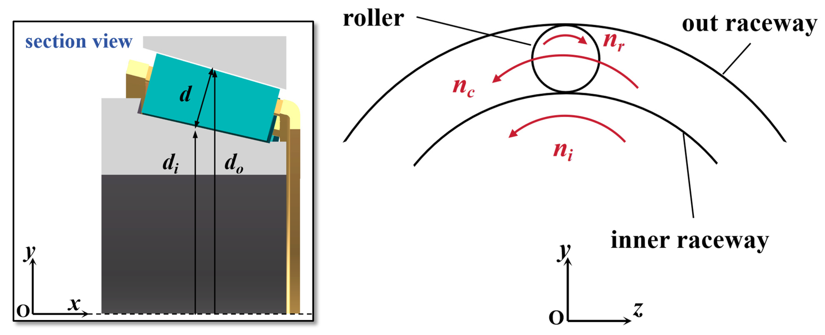
In this paper, research on bearing jet lubrication is carried out using NSK HR 32010XJ tapered roller bearing (Manufactured by Nippon Seiko Co., Ltd., Niigata, Japan) as an example. The geometric structure parameters of this tapered roller bearing are shown in Table 1.

Table 1.
Geometrical parameters of the tested tapered roller bearing.
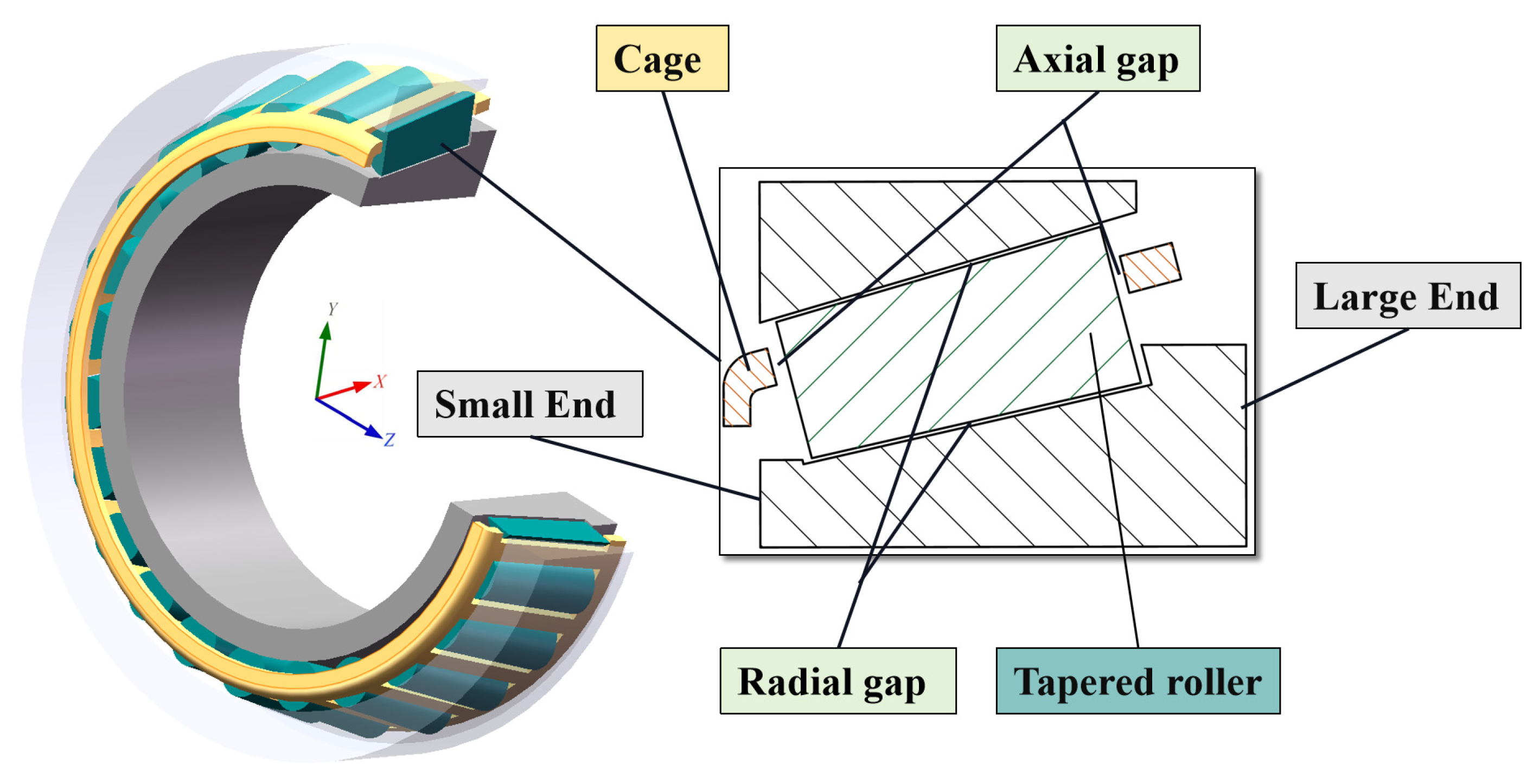
To ensure the accuracy of the numerical simulation of the oil–air two-phase flow field of the bearing under high-speed rotation, it is essential to simplify the model of the tested tapered roller bearing [27]. In practice, the rolling elements, along with the inner and outer rings, are in close contact to ensure the smooth operation of the transmission components. However, this can lead to the fragmentation of the oil and air two-phase flow field during simulations, affecting the smoothness of the numerical flow field simulation. Therefore, to ensure the efficiency of the simulation, as indicated by the reference, the rolling body was scaled down to 95% of the actual size, as shown in Figure 1. The axial gap between the rolling body and the surrounding parts was about 0.15 mm, and the radial gap was about 0.45 mm.
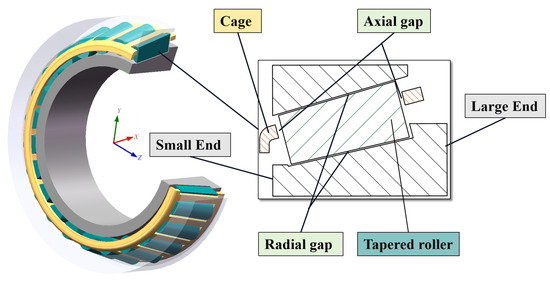
Figure 1.
Simplified geometric model of the tapered roller bearing.
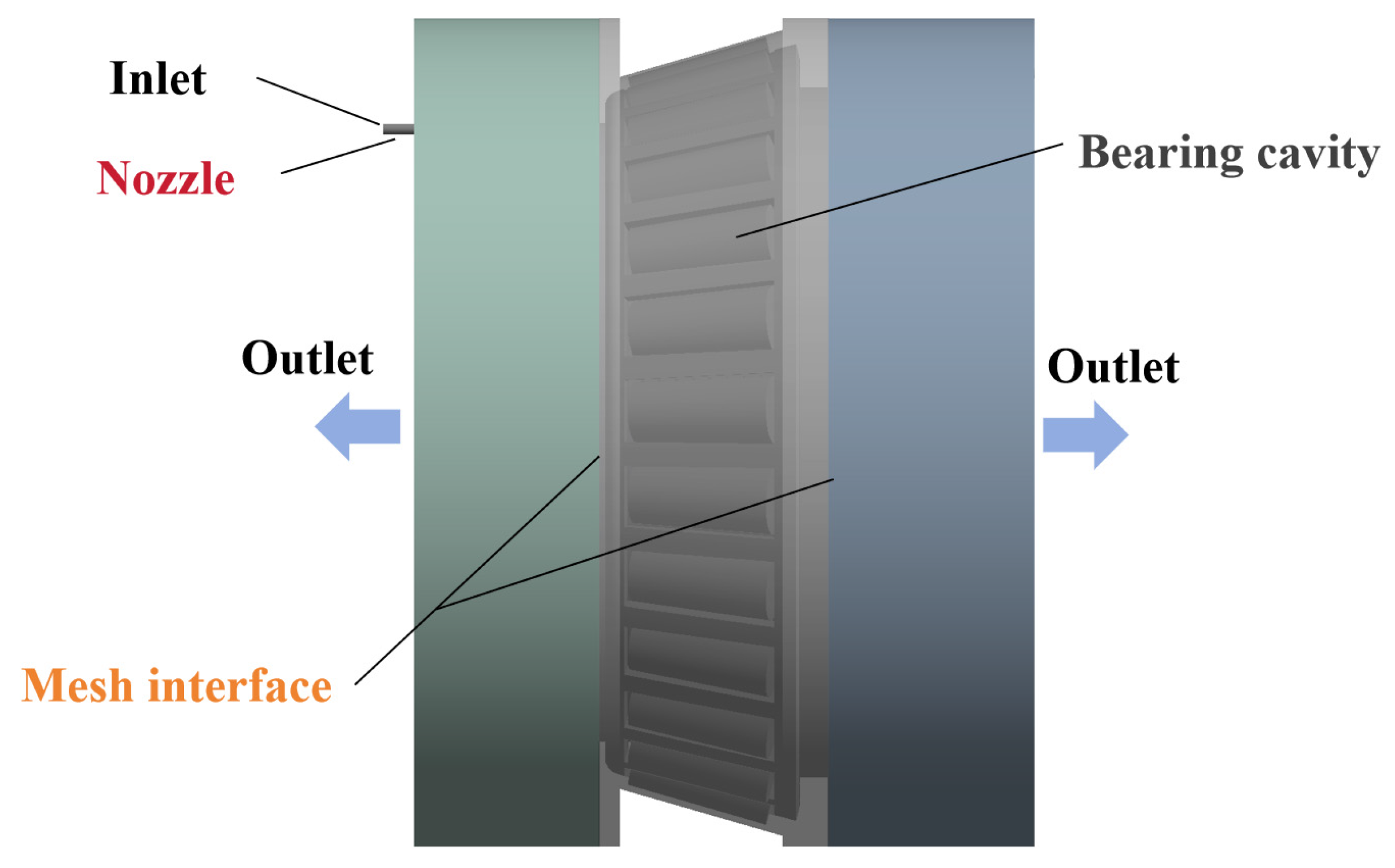
To reduce the computational effort, the flow field region on both sides of the bearing was simplified to a cylindrical shape [27]. Furthermore, based on the simplified tapered roller bearing model, the fluid domain was extracted using Boolean operations, and the computational domain model of the tapered roller bearing under oil jet lubrication was developed. To minimize the effect of lubricant return flow on the simulation results, the width of the fluid domain on both sides of the bearing was set to approximately one time the width of the bearing, as shown in Figure 2.
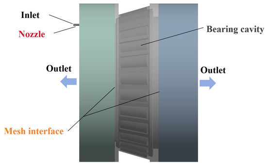
Figure 2.
Numerical simulation model of tapered roller bearing flow field.
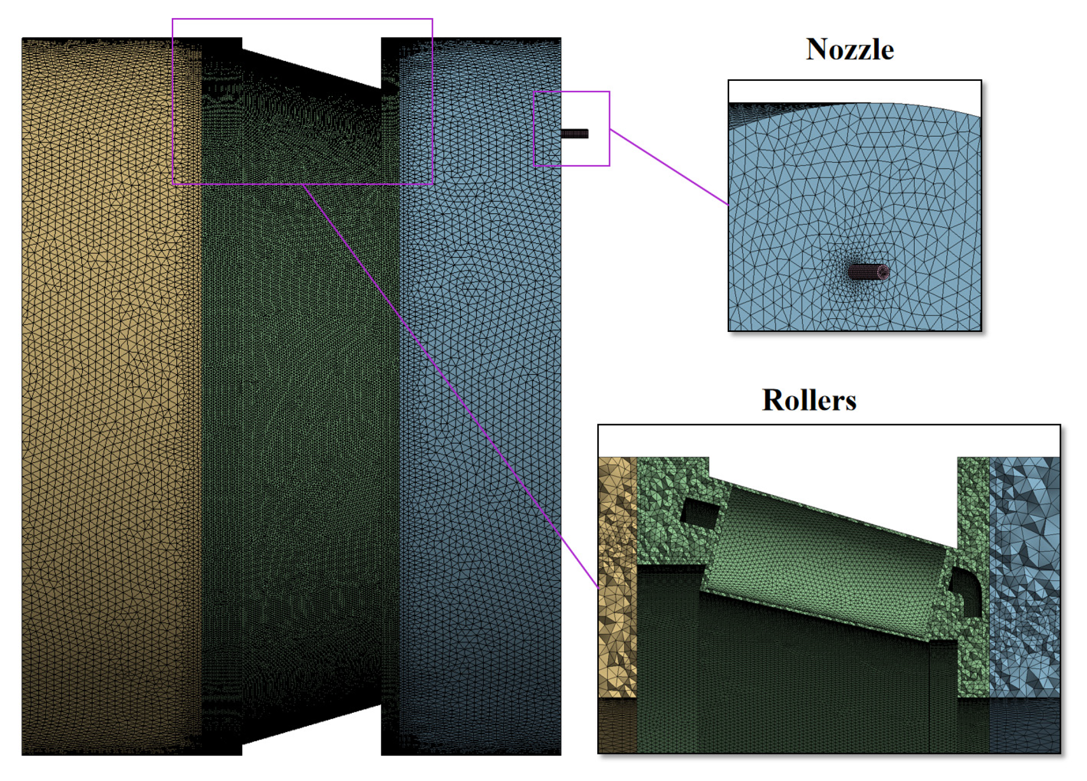
The entire fluid domain mesh was generated using a tetrahedral mesh. To accurately calculate the distribution of lubricants and air in the tapered roller bearing chamber and the oil flow in and out of the bearing, local encryption of the rolling elements, the nozzles, and the mesh interfaces was used, as illustrated in Figure 3.

Figure 3.
Mesh model of the fluid domain.
2.3. Boundary Conditions and Mesh Independence Tests
In the numerical simulation model, the nozzle inlet was specified as a velocity inlet and the outlet was specified as a pressure outlet, with the stipulation that there was no wall slip. Compared to the dynamic mesh technique, the slip mesh technique has been shown to be faster and to reduce calculation times by two-thirds, making it well-suited for the numerical simulation of oil lubrication of bearings [28]. The bearing cavity was defined as a moving region, the inlet and outlet flow fields were set as stationary regions, and the three regions were connected through a grid interface. The SIMPLE solution method was utilized to enhance the convergence of the numerical calculations by concurrently under-relaxing the pressure and momentum.
In this study, the lubricant employed was RIPP 555, a synthetic helicopter transmission system lubricant with a measured density of 920 kg/m3 and a dynamic viscosity of 0.0074 Pa∙s under test conditions.
Following investigation and research [29,30], the motion relationship of the rolling elements, cage, inner ring, and outer ring of the tapered roller bearing is demonstrated in Figure 4, and their rotational speed relationship is demonstrated in Equations (7) and (8).
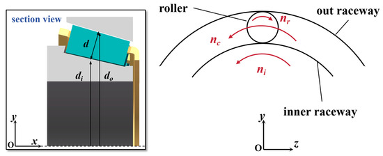
Figure 4.
Tapered roller bearings for each part of the movement relationship.
The extant literature [26] reveals that the rotation of the rolling elements exerts a negligible influence on the outcomes of bearing oil jet lubrication. However, rolling element rotation significantly increases numerical simulation calculation times. Consequently, this paper opted to disregard the rotation of the tapered roller to conduct a numerical simulation study of tapered roller oil jet lubrication.
To quantitatively study the results of the jet lubrication simulation, in this paper, the ratio of the oil flow from the outlet side to the total oil jet flow was defined as the oil return efficiency i, as shown in Equation (9). The higher the return efficiency of the oil, the more adequately the bearing is lubricated.
To mitigate the effects of the mesh on the numerical simulation results, this study further carried out the operation of local mesh refinement on the structure of the rolling body, mesh interface, nozzle, etc., generating 1.41 × 10⁶, 1.99 × 10⁶, 2.93 × 10⁶, and 4.18 × 10⁶ meshes, respectively, to conduct mesh independence verification. In Fluent, the kinematic parameters for numerical simulation were configured as follows: a bearing speed of 3000 rpm, inlet diameter of 1 mm, inlet velocity of 37.2 m/s, and lubricant RIPP of 555. The oil return efficiency of the lubricant was utilized as the evaluation index, with the results presented in Figure 5. It has been demonstrated that as the number of grids exceeds 1.99 × 10⁶, the oil return efficiency of the numerical simulation exhibits minimal fluctuations and remains relatively stable. To enhance calculation efficiency, the simulation study was conducted using 1.99 × 10⁶ meshes.
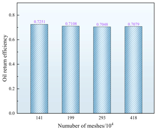
Figure 5.
Grid independence verification.
3. Oil Return Efficiency Principle Test Verification
3.1. Tapered Roller Bearing Jet Lubrication Test Rig
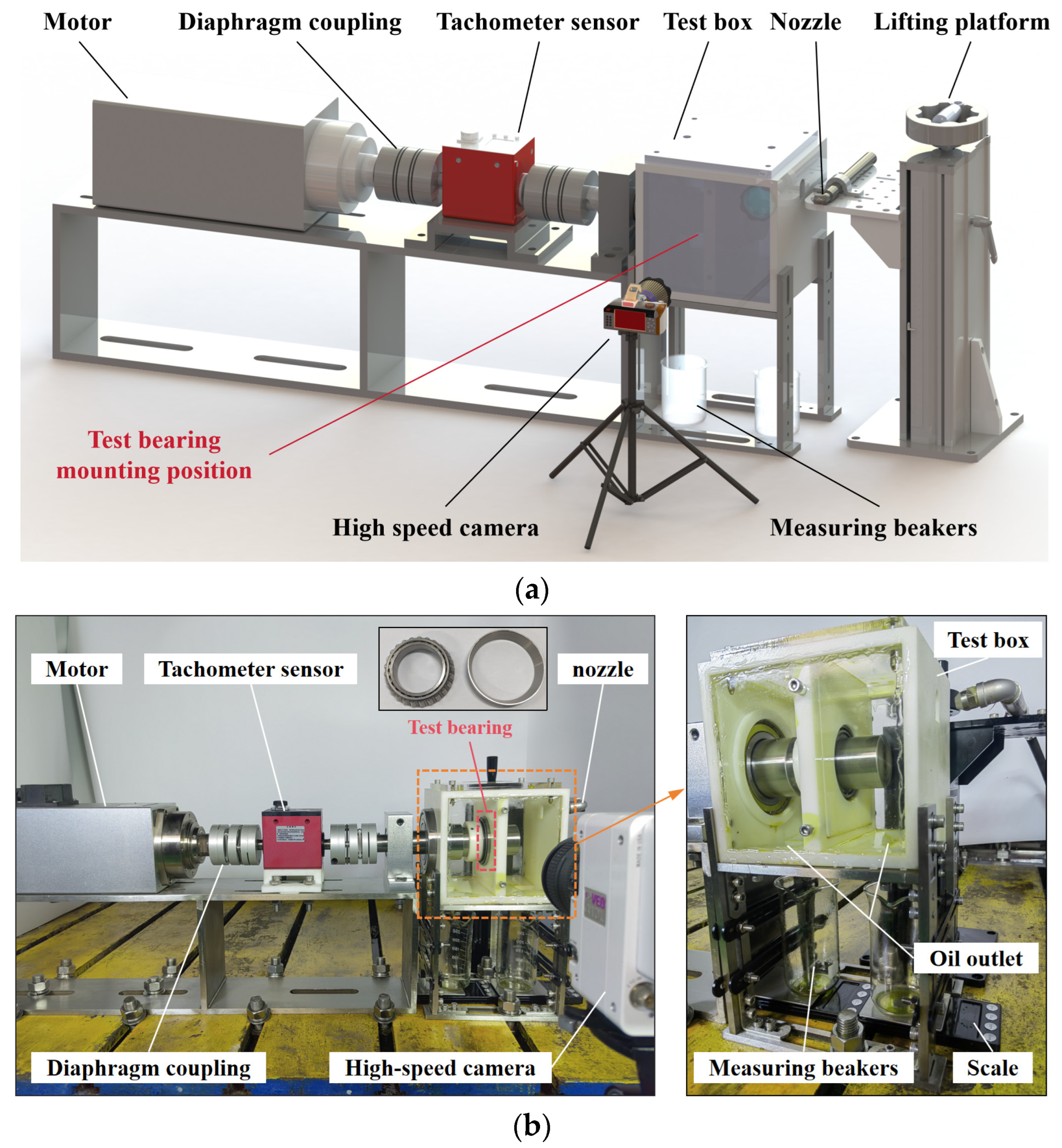
To validate the accuracy of the numerical simulation model for the oil jet lubrication of tapered roller bearings, a tapered roller bearing oil jet test rig was constructed in this study to conduct experimental research, as shown in Figure 6. The tapered roller bearing oil jet lubrication test rig consists of a motor drive device, bearing oil jet lubrication test box, a flow measurement device, an oil sliding system, and a high-speed camera. Among them, the drive system consists of a motor, coupling, and speed sensor, and the motor model is KNS3500B-12/0.37TMP (Manufactured by Guangzhou Haopai Electromechanical Equipment Co., Ltd., Guangzhou, China). The bearing oil jet lubrication test box, composed of a 3D-printed resin skeleton and transparent acrylic plates, allows for the observation of the oil and air distribution inside. The tapered roller bearing is installed in the center of the chamber, positioned on a partition, and the bottoms of the two cavities in the box are equipped with oil outlets. Flow measurement was achieved using two beakers positioned at the outlet, along with electronic scales with a precision of 0.01 g. The pump utilized within the sliding oil system is an S3HV30W1B-KC0608/80 gear pump (Manufactured by Fengmao Hydraulic Technology, Foshan, China), which is capable of achieving an oil flow rate of up to 24 L/min. The test utilized the Phantom VEO410L high-speed camera (Manufactured by Vision Research, Wayne, NJ, USA), which possesses a resolution of 1280 × 800 and a sampling frequency of 5200 Hz.

Figure 6.
Tapered roller bearing jet lubrication test rig: (a) test rig schematic diagram; (b) test rig physical picture.
The bearings for the oil jet lubrication test are of the same type as the bearings for the numerical simulation. The speeds of the tapered roller bearings tested in the trials were 1000 rpm, 3000 rpm, and 5000 rpm. During testing, we first checked whether the installation of each part of the connection was normal. Then, we turned on the gear pump radiator and the motor and adjusted the speed control valve to control the nozzle flow to the desired test flow. Furthermore, the motor speed was adjusted to the test speed via the frequency converter. After waiting for the speed to stabilize, the gear pump was turned on to spray oil at the test position for 5 s. Once the oil in the two cavities of the box had fully flowed into the beaker, the values on the two electronic scales were recorded. The oil return efficiency was then calculated, and the flow field images captured by the high-speed camera were preserved. The above operation was repeated to obtain the oil return efficiency and flow field images of bearing jet lubrication under different operating conditions.
3.2. Comparison of Experimental and Numerical Results
Figure 7 shows the bearing oil injection lubrication test position during the test, the bearing vertical simulation, and the test position, which is located in the lower gap of the small end of the bearing. The jet flow rate for the test was 105 L/h, the nozzle diameter was 1 mm, and the lubricant selected was RIPP 555.
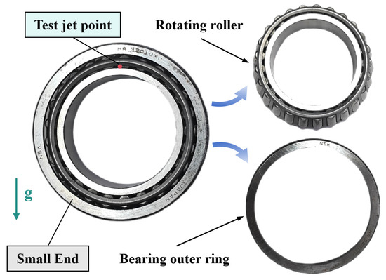
Figure 7.
Tapered roller bearing test oil jet points.
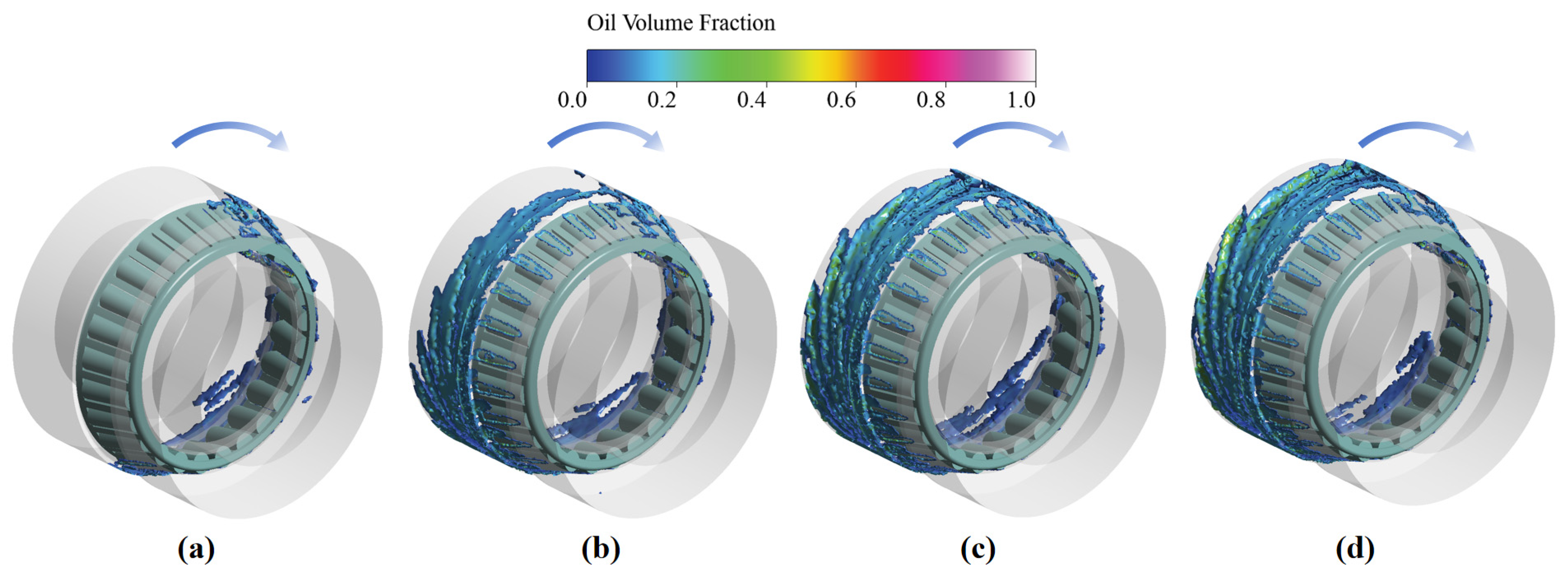
According to Figure 6, the parameters of the bearing oil jet lubrication simulation model are set to carry out the numerical simulation study under the test conditions. The variation in the lubricant distribution in the bearing chamber over time is illustrated in Figure 8. The results illustrate that at the bearing speed of 3000 rpm, when the simulation calculation time reaches 0.075 s, the distribution of the lubricant in the chamber basically reaches a stable state, and the key position of the bearing is lubricated.
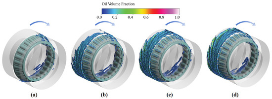
Figure 8.
The distribution of the lubricating oil volume fraction in the fluid domain as a function of time (where the rotating speed is 3000 rpm): (a) 0.025 s; (b) 0.05 s; (c) 0.075 s; (d) 0.1 s.
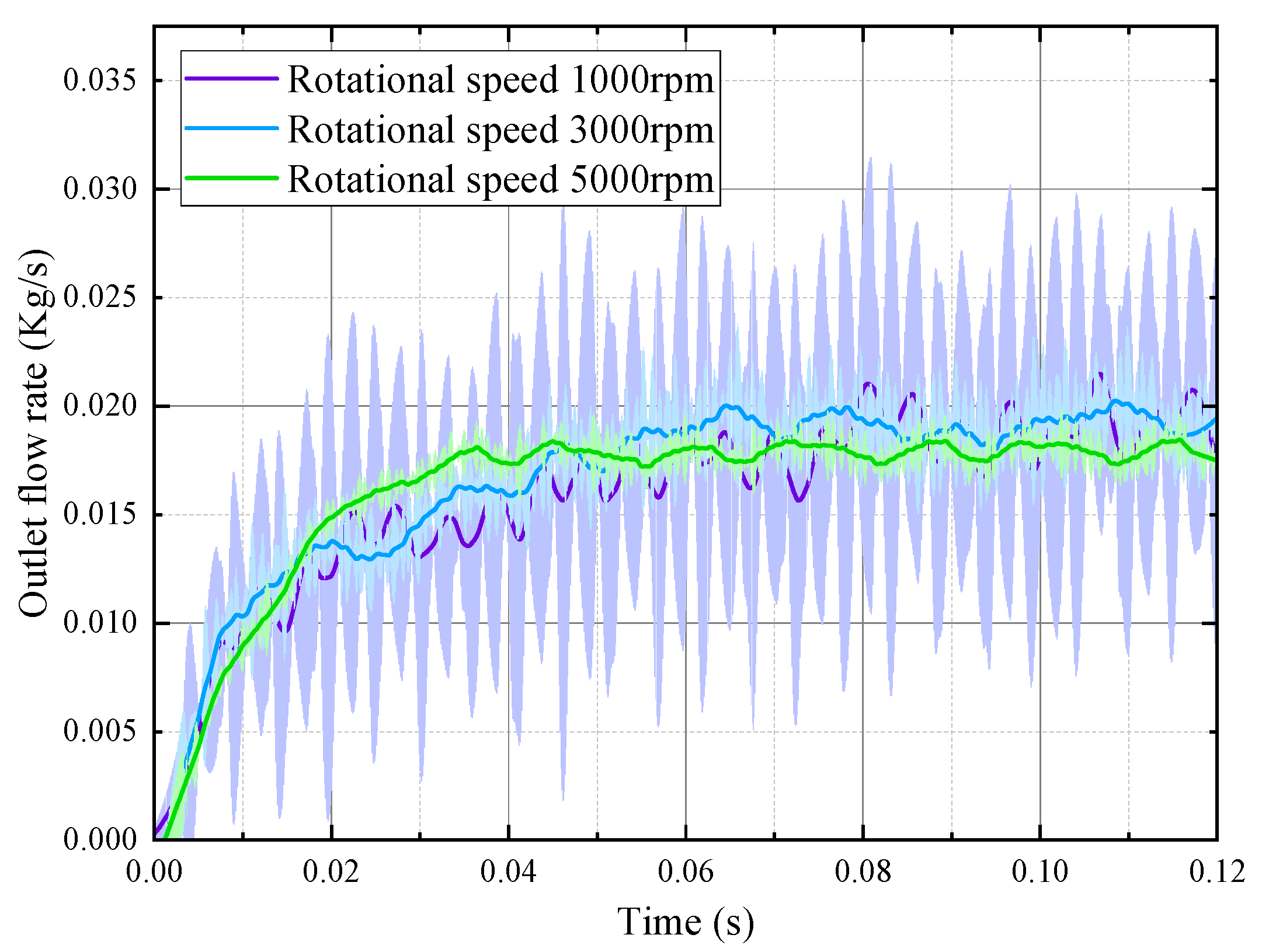
Figure 9 shows the variation in flow velocity at the outlet on one side of the bearing under various rotational speeds. As the bearing speed increases, the time for the outlet flow velocity to reach stability also decreases, while the fluctuations in flow velocity gradually diminish. It takes the longest time to reach the steady state, at about 0.09 s, at a bearing speed of 1000 rpm. Therefore, to ensure that the flow field in the chamber reaches a steady state, the simulation calculation time was set to 0.15 s in this paper.
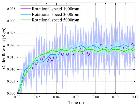
Figure 9.
Monitoring the curve of lubricant flow velocity through the surface as a function of time.
Figure 10 shows the comparison between the experimental and Fluent simulation of the lubricant distribution in the bearing chamber at 0.15 s. The high-speed camera images of the test show that as the rotational speed increases, the oil column passing through the tapered roller bearing becomes progressively shorter (as indicated by the red circle in Figure 10). Additionally, more oil from the left chamber splashes onto the wall of the box, while there is no significant change in the right chamber wall. This observation closely matches the cross-sectional oil volume distribution obtained from the simulation.
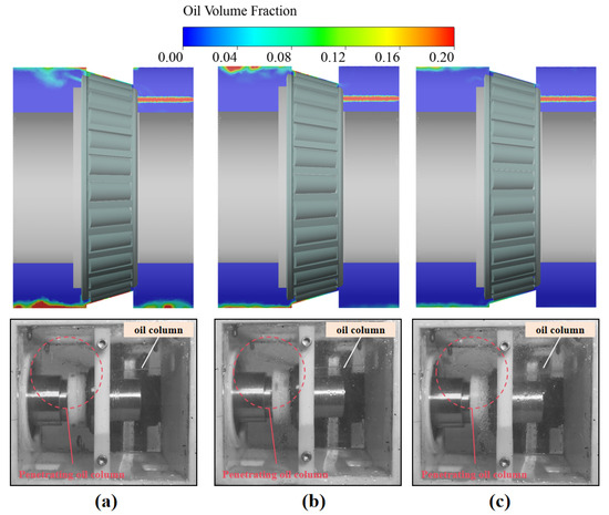
Figure 10.
Comparison of experimental and numerical simulation flow fields: (a) 1000 rpm; (b) 5000 rpm; (c) 8000 rpm.
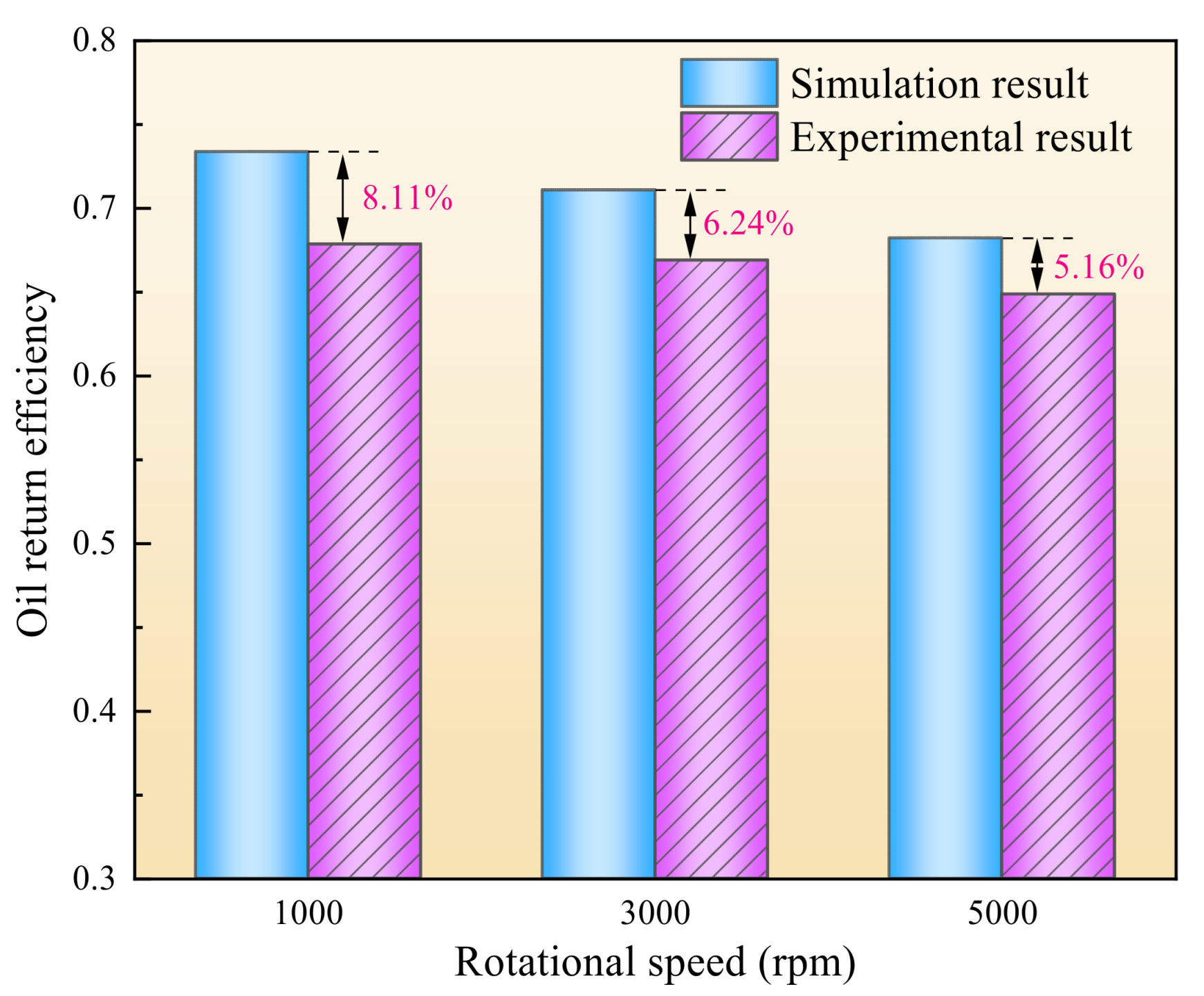
Figure 11 presents a comparison between the oil return efficiency tests and simulations. The results indicate that the oil penetration rate, which characterizes the oil return efficiency for both the simulation and the test, decreases progressively with increasing rotational speed. The measured oil penetration rate from the test and the numerical simulation results exhibit a similar trend, with specific relative errors of 8.11%, 6.24%, and 5.16%, respectively, all of which are maintained within 10%. Here, the oil penetration rate is defined as the ratio of the oil return flow to the oil supply flow, i.e., the proportion of oil returned compared to the amount of oil supplied during the same time period. While the oil supply can be accurately measured, the experimentally determined oil return quantity may be underestimated due to small amounts of residual oil remaining in the rolling bearing test box. Consequently, the experimental findings are slightly lower than the numerical results. Overall, this confirms the consistency between the test and the simulation, thereby validating the accuracy of the numerical simulation model. Additionally, it can be observed in Figure 11 that the test oil return efficiency is consistently slightly lower than the simulation, potentially due to vibrations in the test box caused by the rotating motor of the test stand, which may shift the jet point and introduce errors.
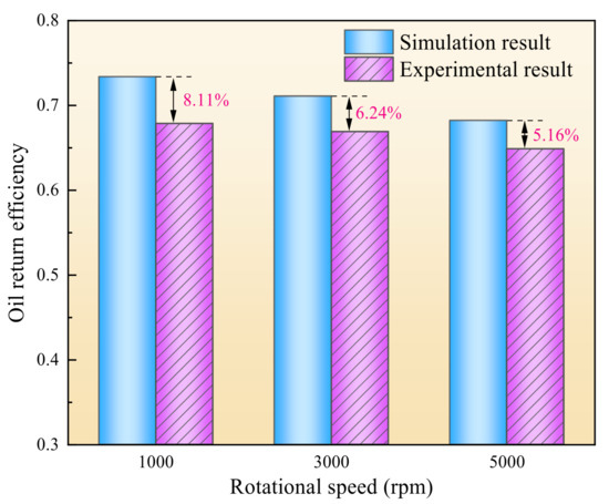
Figure 11.
Comparison of oil return efficiency tests and numerical simulations.
4. Analysis and Verification
4.1. Effects of Jet Lubrication Position
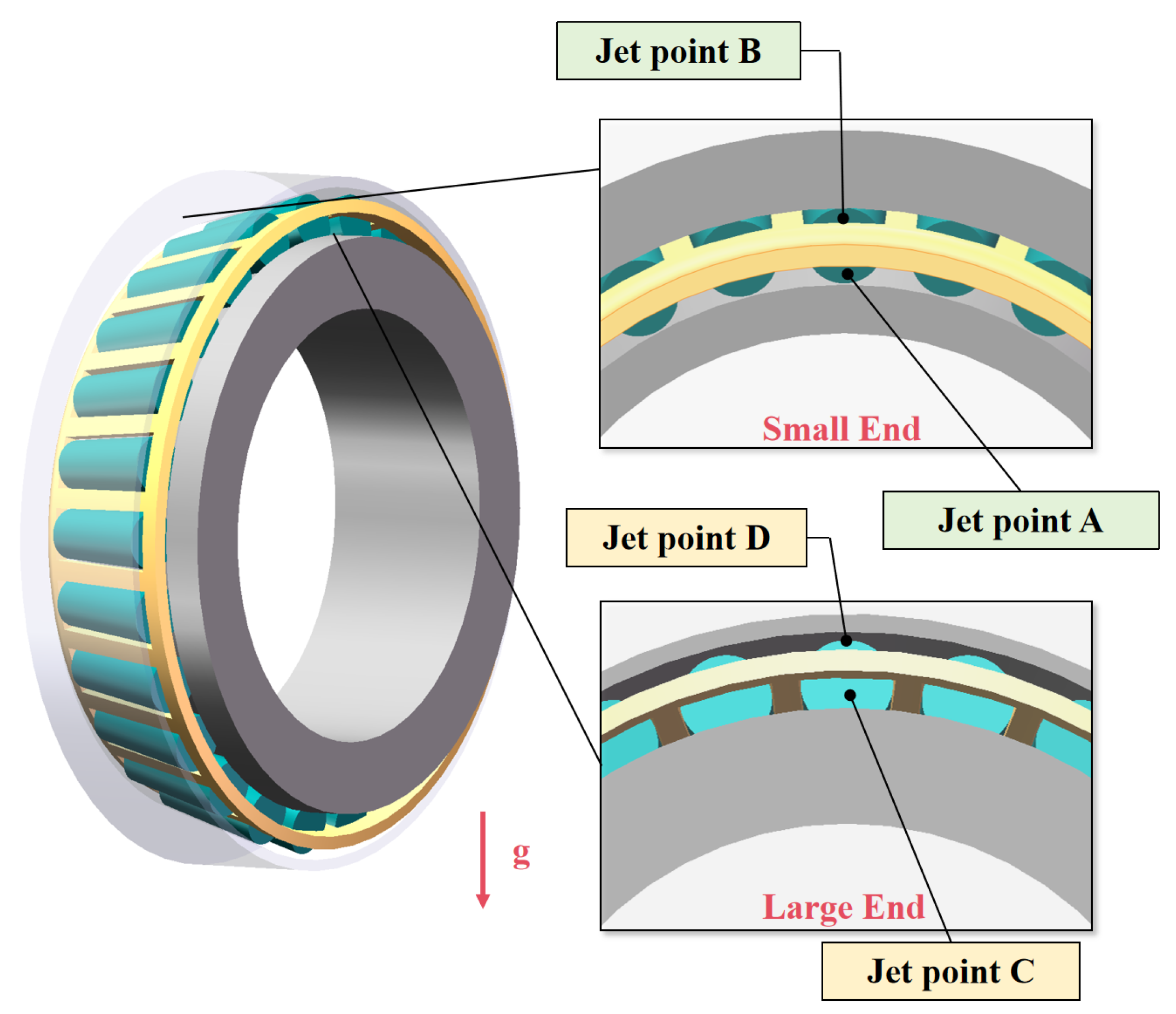
To investigate the effects of the position of oil jet lubrication on the lubrication performance of the bearings, this paper investigates four jet point positions, as shown in Figure 12, which are located on the large and small ends of the tapered roller bearings.
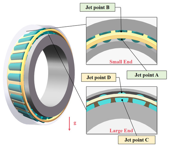
Figure 12.
Jet position of tapered roller bearing.
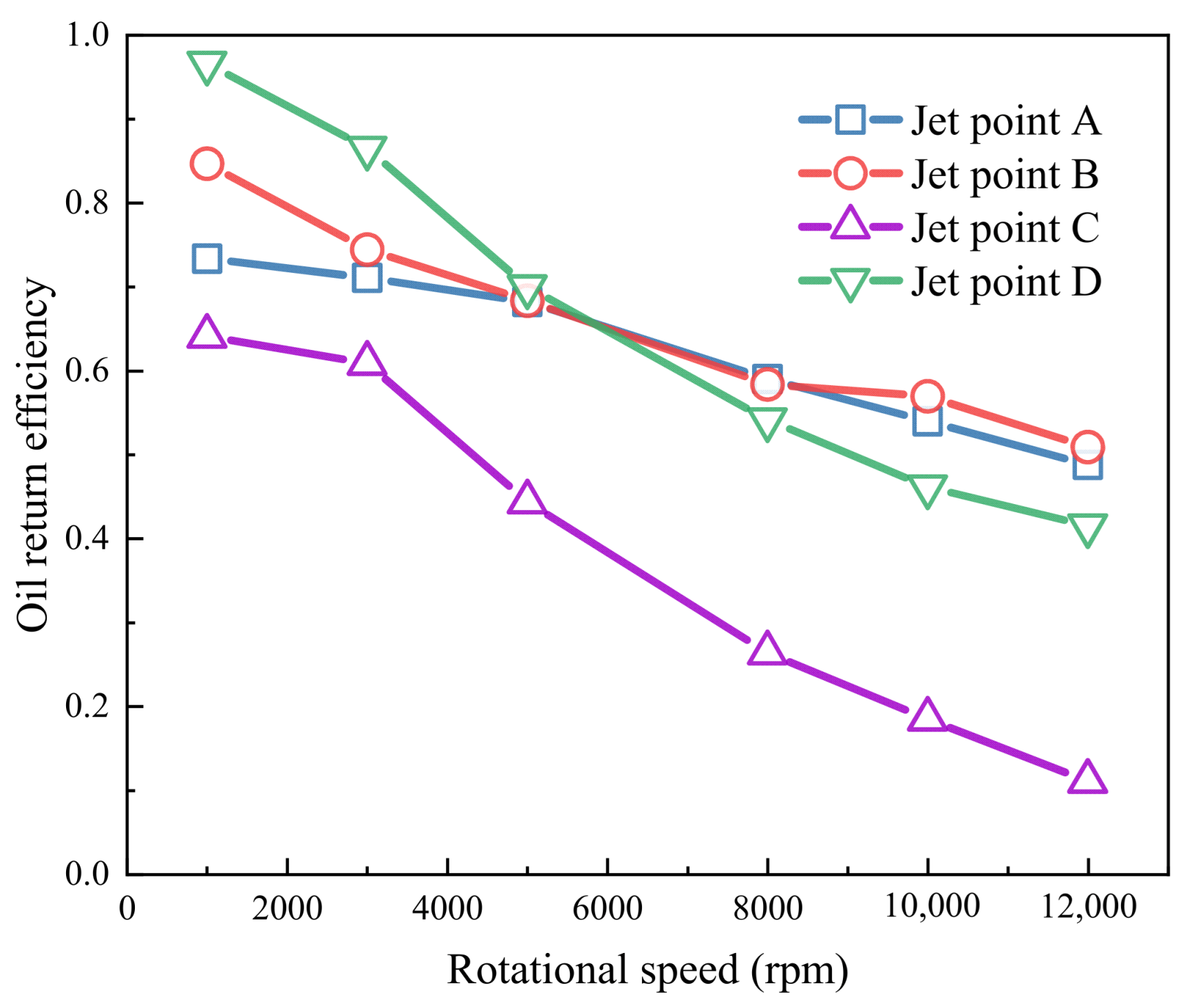
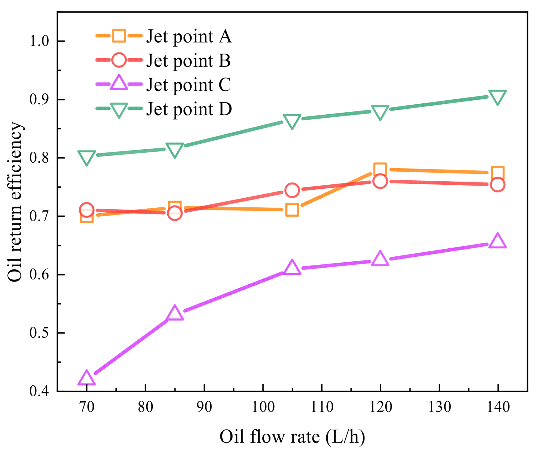
Figure 13 shows oil return efficiency versus the jet position and bearing speed. The results show that as the rotational speed increases, the oil return efficiency gradually decreases, and the decreasing trend gradually increases. Tapered roller bearings generate a pumping effect when rotated at elevated speeds, resulting in the flow of oil from the inner ring to the outer ring, and from the small end to the large end. The magnitude of the pumping effect increases with increasing rotational speed. Consequently, the decline in the oil return efficiency at the jet point on the small end is substantially less pronounced than that at the large end. Furthermore, the oil return efficiency at jet point C is also less significant than that at jet point D. This finding indicates that the jet from the outer ring at the large end can result in a reduction in the pumping effect.

Figure 13.
Oil return efficiency at different jet positions.
This pumping effect increases gradually as the speed rises, and the lubricant is more readily transferred from the small end than the large end. When the bearing rotational speed is sufficiently elevated, the oil return efficiency from the small end eventually exceeds that of the large end. Consequently, when lubricating high-speed bearings with an oil jet, it is advisable to use the jet from the small end.
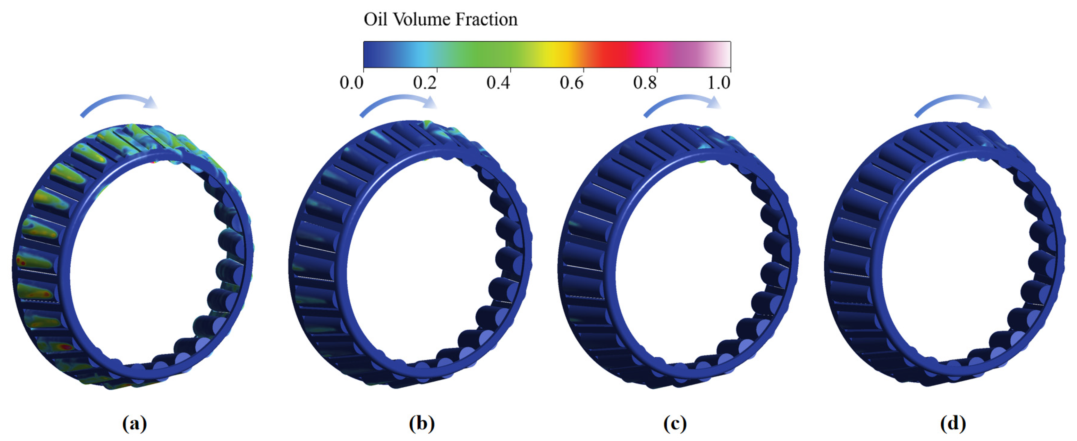
Figure 14 shows the lubricating oil distribution of rolling elements in the bearing when the jet point is A. The results show that as the bearing speed increases, the lubricant on the surface of the rolling body gradually decreases. At the same time, the oil that is further away from the injection point reduces, and the lubrication effect gradually decreases. This phenomenon can be explained by the action of tapered roller bearings rotating at high speed. The centrifugal force effect is produced, resulting in the roller being attached to the oil and the oil being thrown outward. This leads to a reduction in the amount of oil attached to the roller and the migration of the oil film to the large end of the roller. Concurrently, the centrifugal force effect will undergo a progressive escalation with an augmentation in rotational velocity, culminating in a steady decline in the volume fraction of oil and gas on the roller.

Figure 14.
Position A: lubricating oil distribution of rolling elements in bearing: (a) 1000 rpm; (b) 5000 rpm; (c) 8000 rpm; (d) 12,000 rpm.
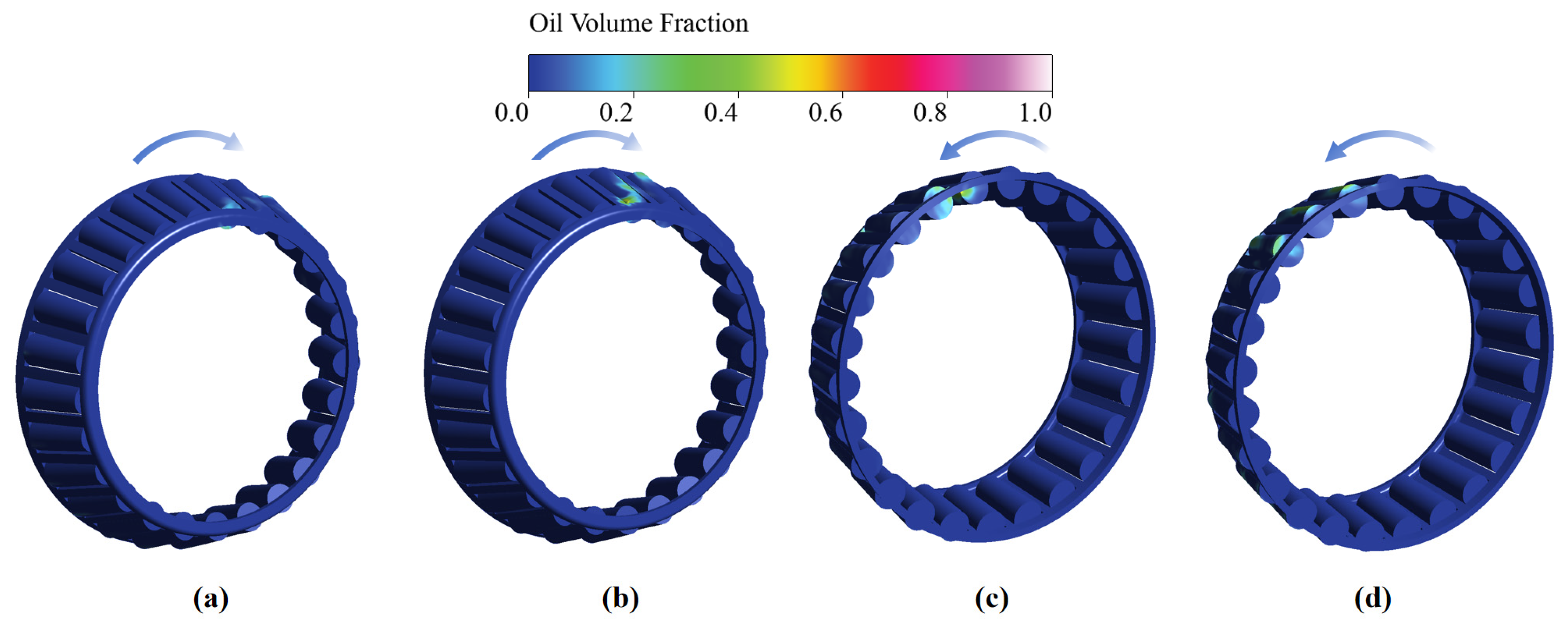
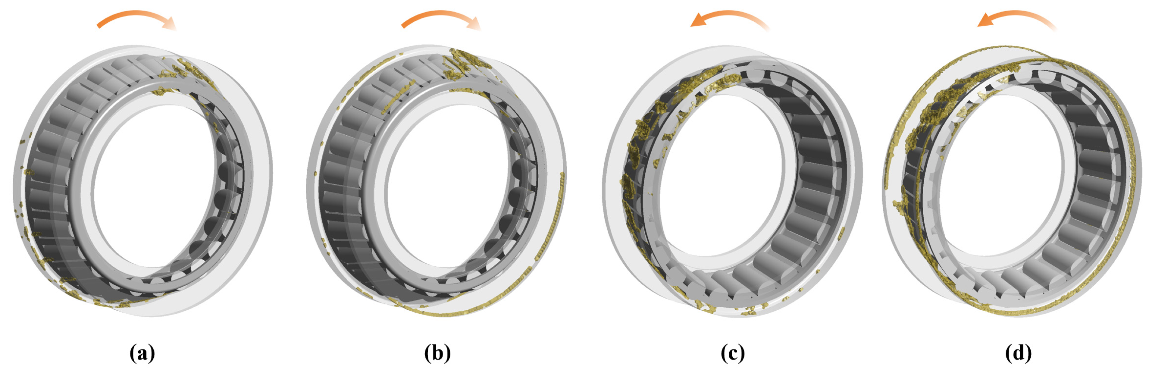
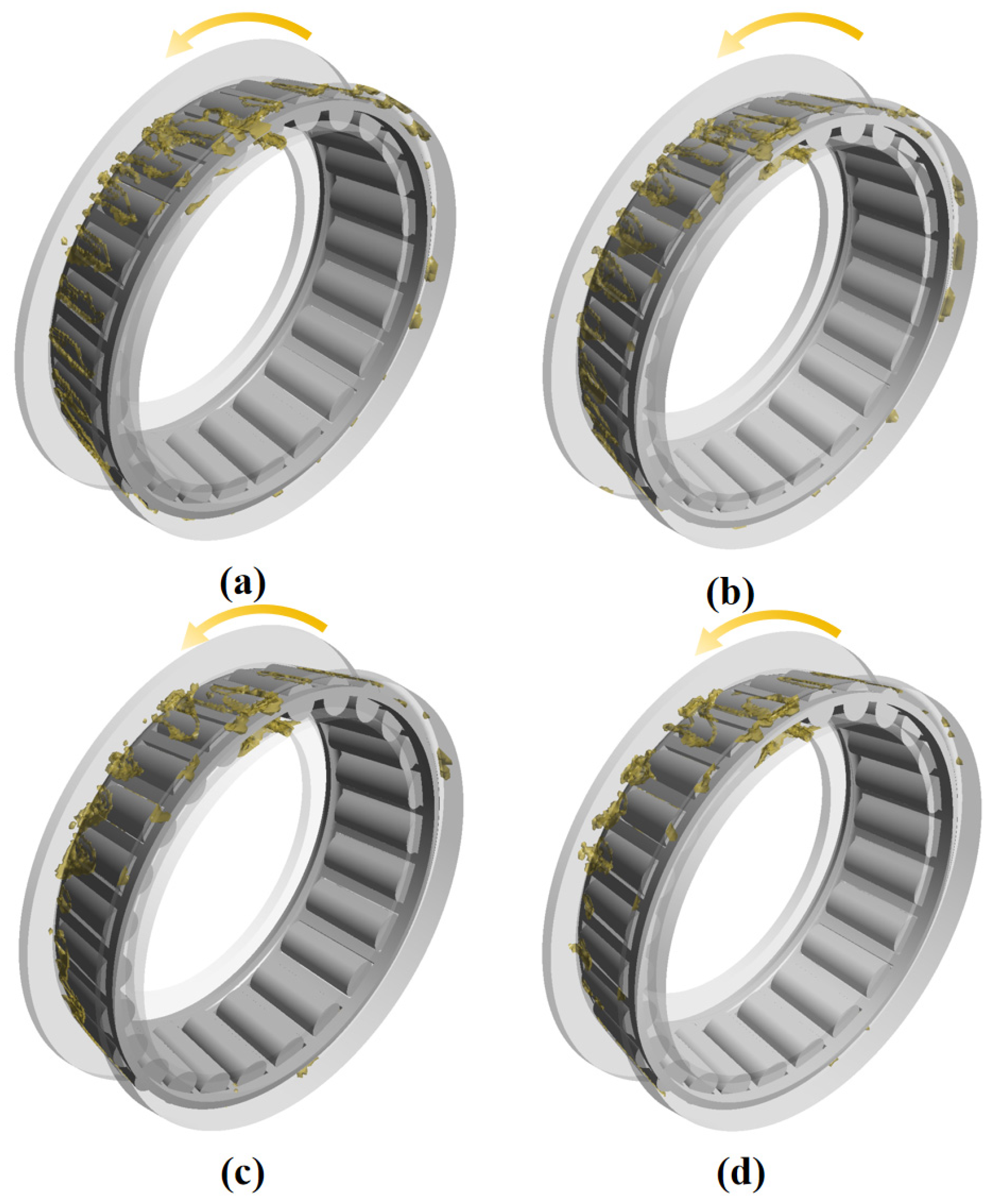
Figure 15 and Figure 16 show the oil distribution on the surface of the rolling body and the oil distribution inside the bearing chamber at different jet points at a bearing speed of 10,000 rpm, respectively. When the bearing speed is 10,000 rpm and the jet point is C, there is less oil on the surface of the rolling element, and most of the oil remains in the part near the face of the large end; the lowest amount of oil passes through the bearing, and the lubrication effect is poor.
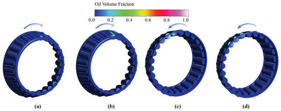
Figure 15.
Lubricating oil distribution of bearing rolling element at different jet positions (where the rotating speed is 10,000 rpm): (a) jet point A; (b) jet point B; (c) jet point C; (d) jet point D.
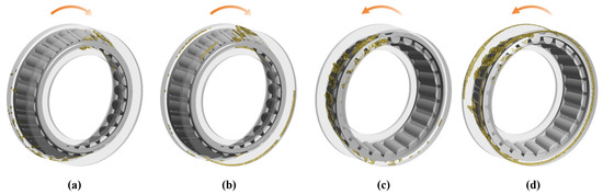
Figure 16.
Lubricating oil distribution of bearing chambers at different jet positions (where the rotating speed is 10,000 rpm and lubricant volume fraction is 0.05): (a) jet point A; (b) jet point B; (c) jet point C; (d) jet point D.
4.2. Effects of Jet Lubrication Flow Rate
Figure 17 shows the oil return efficiency with an incident flow rate for a bearing speed of 3000 rpm and a nozzle diameter of 1 mm. The oil return efficiency increased gradually with an increase in the incident flow rate, and the large end of the tapered roller bearing became more sensitive to changes in the flow rate compared to the small end. Consequently, when oil jet lubrication was employed at the large end, the incident flow rate could be appropriately increased to enhance the lubrication effect.
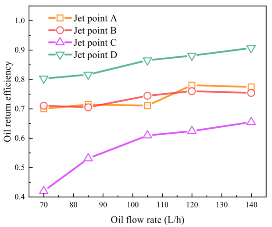
Figure 17.
Oil return efficiency at different oil flow rates (where the rotating speed is 3000 rpm).
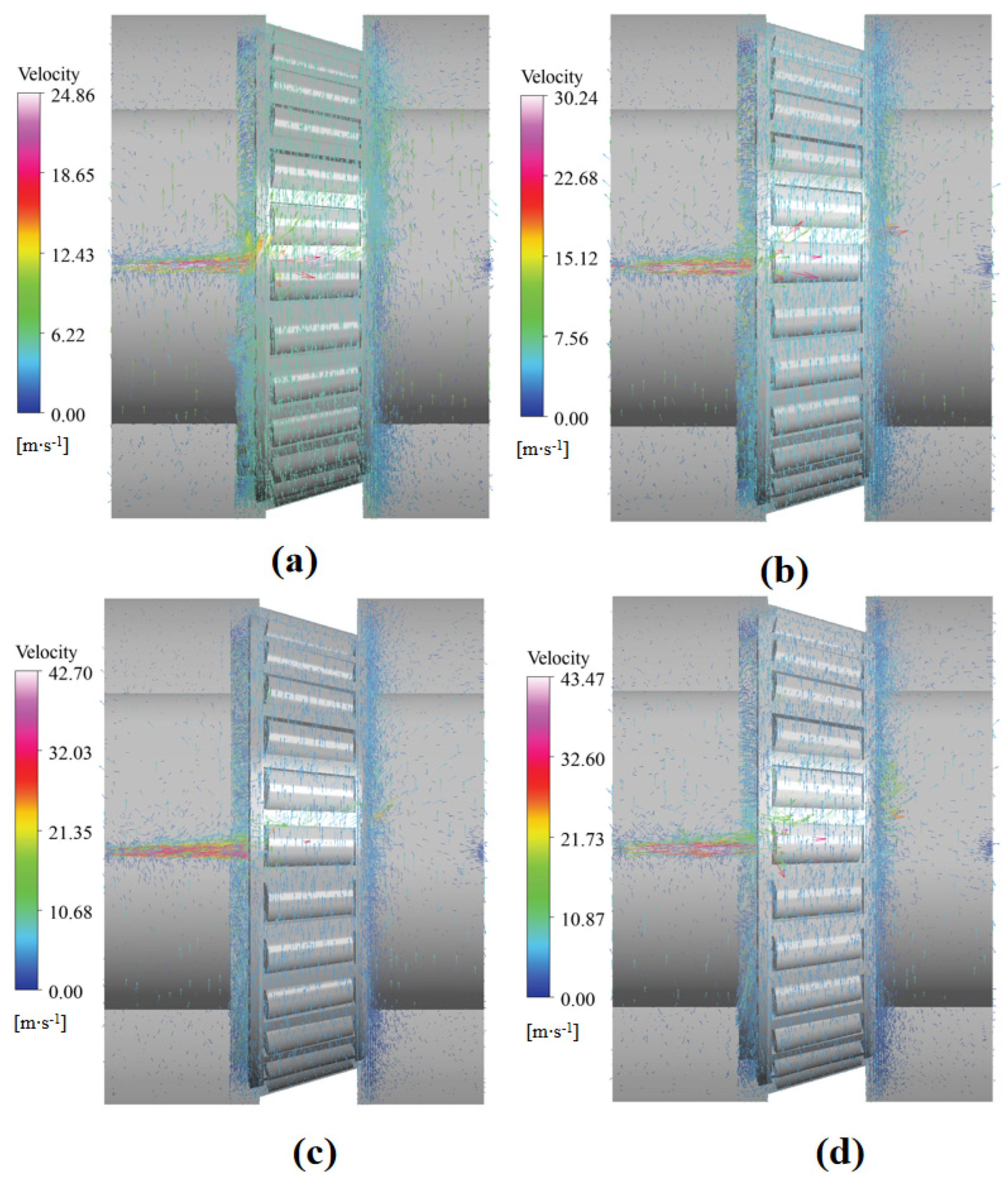
Figure 18 depicts the velocity vector distribution of the oil in the bearing chamber at a speed of 3000 rpm and jet point C at the face of the large end. It has been seen that the oil displays elevated velocities upon its ejection and that this velocity decreases rapidly upon contact with the bearing element. After contacting the bearing element, a proportion of the oil is reflected back, thereby increasing the speed; a proportion of the oil remains in the bearing chamber and passes through the bearing at a lower speed with the movement of the rollers, thus lubricating the rolling elements. As the oil flow rate increases, the oil return efficiency increases, and more oil passes through the bearing, contributing to bearing lubrication.

Figure 18.
Velocity vector in the bearing chamber at various oil flow rates (where the rotational speed is 3000 rpm): (a) 70 L/h; (b) 85 L/h; (c) 105 L/h; (d) 120 L/h.
Figure 19 depicts the lubricating oil distribution of the bearing chamber (lubricant volume fraction of 0.1) at a rotating speed of 3000 rpm and jet point C at the face of the large end. It has been seen that an increase in the incident flow rate results in a gradual reduction in the lubricating oil retained in the bearing cavity, an enhancement of the oil return efficiency, and an improvement in the lubrication effect.

Figure 19.
Lubricating oil distribution of the bearing chamber at various oil flow rates (where the rotating speed is 3000 rpm with a lubricant volume fraction of 0.1): (a) 70 L/h; (b) 85 L/h; (c) 105 L/h; (d) 120 L/h.
As demonstrated in Figure 19, an enhancement in the oil flow rate results in a progressive intensification of the interaction between the air and lubricating oil. This process leads to the incorporation of air into the oil, resulting in the formation of bubbles that disrupt the integrity of the oil film. Consequently, this phenomenon leads to an augmentation in the thickness of the lubricating oil film in that specific region, thereby elevating the risk of metal contact and exacerbating wear. Therefore, it is necessary to appropriately reduce the flow rate of the oil and mitigate the effect of air on the lubricating oil. As demonstrated in Figure 17, it is evident that as the oil flow rate is increased, the trend of an increase in oil return efficiency becomes less pronounced. Therefore, we can use a smaller oil flow rate for tapered roller bearing oil injection lubrication, which can improve the lubrication performance of bearings under the condition of ensuring a high oil return efficiency. The maximum recommended oil flow rate for this apparatus is approximately 105 L/h.
4.3. Effects of the Nozzle Diameter
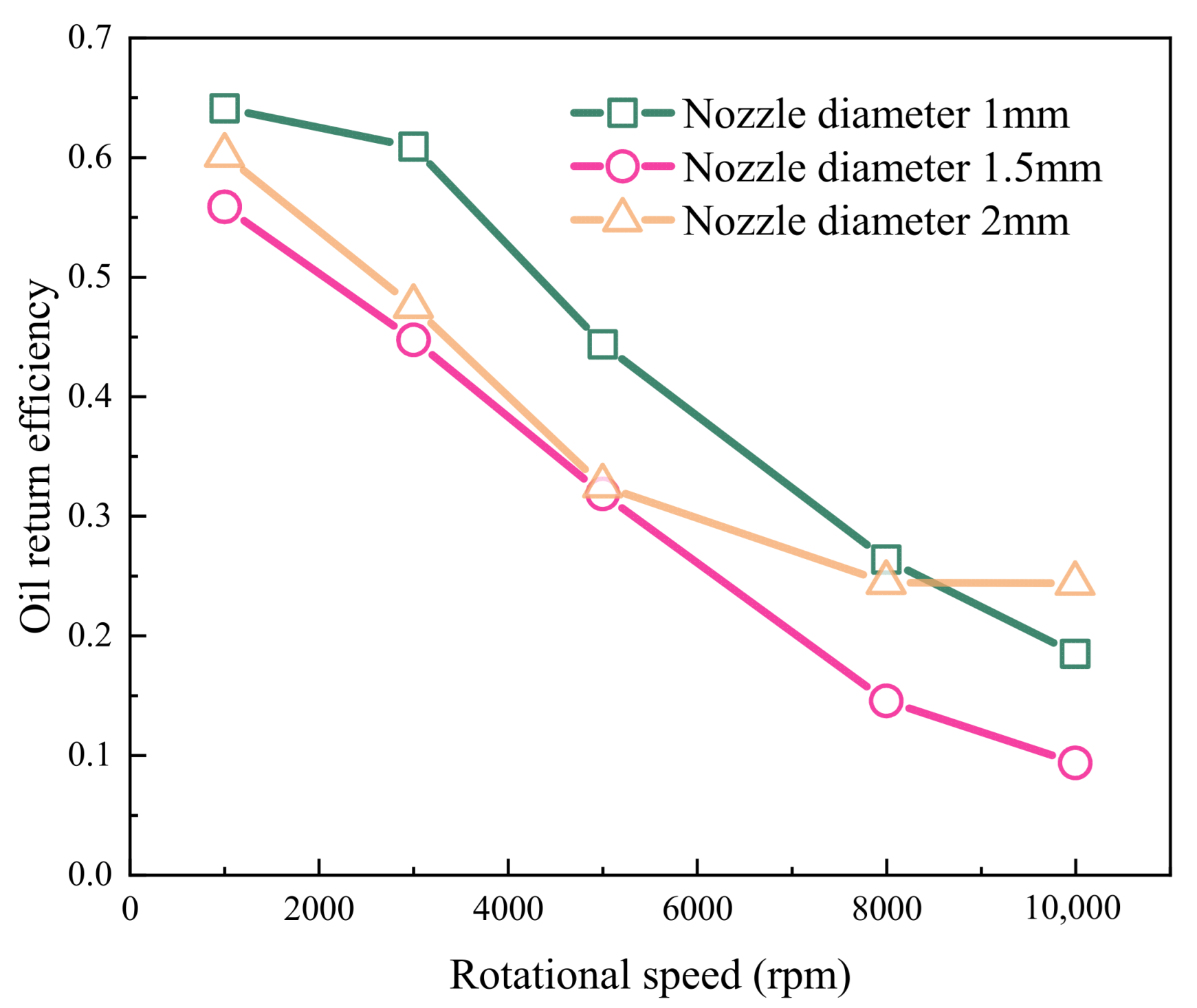
In this paper, a simulation study was conducted to investigate the effect of nozzle size on the lubrication performance of bearing injection. Since the rest of the injection positions have small clearances, only injection point C on the large end is studied here. In performing the simulation setup, only the size of the inlet was changed, which was set to 1 mm, 1.5 mm, and 2 mm, respectively, and the inlet velocity was set to 37.2 m/s in all cases. The relationship between the changes in the oil return efficiency under this condition was obtained and is illustrated in Figure 20.

Figure 20.
Oil return efficiency at different nozzle diameters (where the rotating speed is 3000 rpm).
Figure 20 illustrates how, for different nozzle diameters, the oil return efficiency decreased with increasing rotational speed due to the pumping effect produced when the tapered roller bearing rotated at high speed, with the best oil return efficiency achieved at a nozzle diameter of 1 mm.
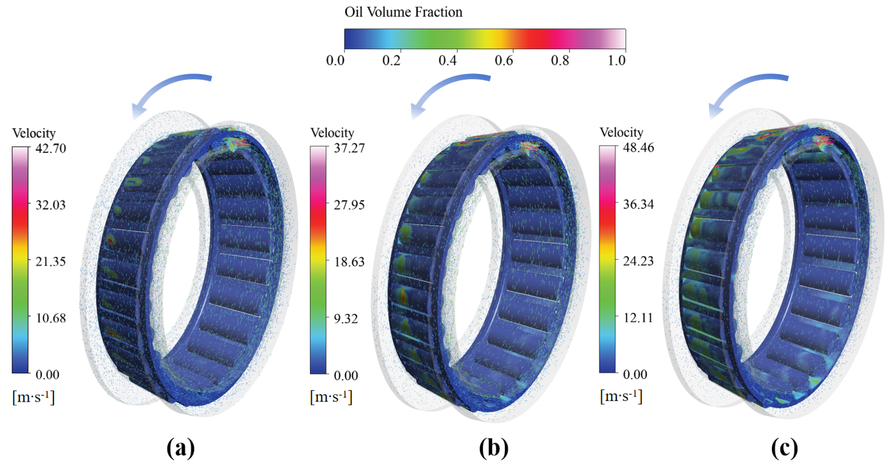
Figure 21 illustrates the oil volume distribution and velocity vector plots on the rolling body surface, as well as the lubricant volume distribution in the bearing chamber, for various nozzle diameters at a rotation speed of 3000 rpm and jet position point C at the large end, respectively. As the nozzle diameter increases, the oil on the rolling body surface gradually increases, and the stagnant oil in the bearing cavity also increases. This may increase the churning torque, leading to a reduction in oil utilization, which is detrimental to bearing lubrication.

Figure 21.
Vector plot of bearing roller lubricant distribution versus velocity in the bearing chamber at different nozzle diameters (where the rotating speed is 3000 rpm): (a) nozzle diameter 1 mm; (b) nozzle diameter 1.5 mm; (c) nozzle diameter 2 mm.
4.4. Effects of the Injection Angle
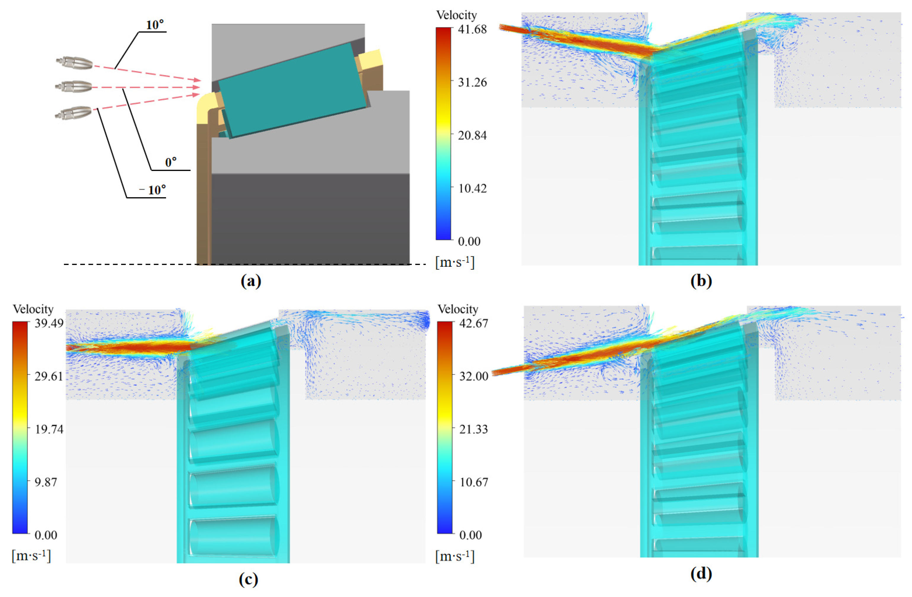
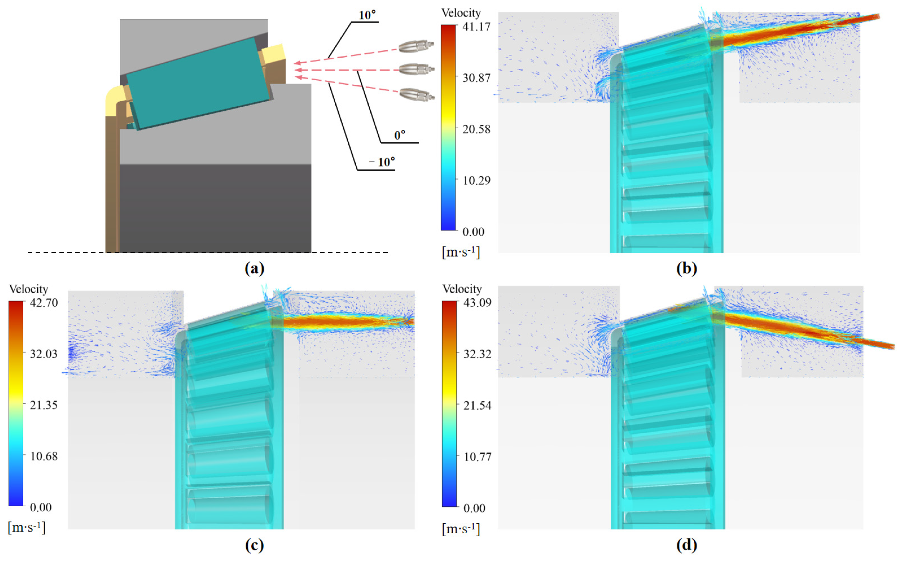
Due to bearing oil injection lubrication, the lubricant is not always positively sprayed compared to the bearing, so it is essential to investigate the injection angle; as such, this paper focuses on the pitch angle injection. The nozzle diameter was set to 1 mm, and the inlet velocity was 37.2 (flow rate 105 L/h) to carry out the study of bearing oil injection lubrication at different positions with different incident pitch angles. The oil velocity vector diagrams in the bearing cavity were obtained as shown in Figure 22, Figure 23, Figure 24, Figure 25 and Figure 26.
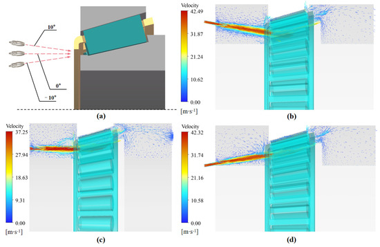
Figure 22.
Vector plot of incident bearing cavity velocities at different angles at Position A (where the rotating speed is 3000 rpm): (a) incident diagram; (b) angle of injection 10°; (c) angle of injection 0°; (d) angle of injection −10°.
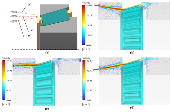
Figure 23.
Vector plot of incident bearing cavity velocities at different angles at Position B (where the rotating speed is 3000 rpm): (a) incident diagram; (b) angle of injection 10°; (c) angle of injection 0°; (d) Angle of injection −10°.

Figure 24.
Vector plot of incident bearing cavity velocities at different angles at Position C (where the rotating speed is 3000 rpm): (a) incident diagram; (b) angle of injection 10°; (c) angle of injection 0°; (d) angle of injection −10°.
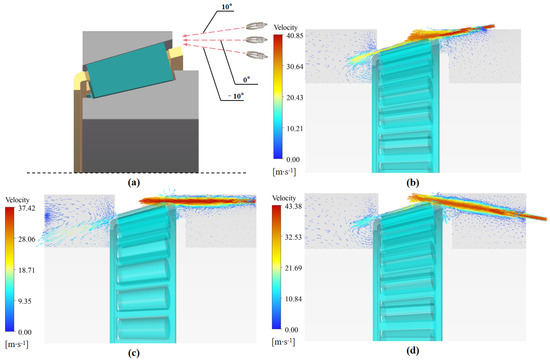
Figure 25.
Vector plot of incident bearing cavity velocities at different angles at Position D (where the rotating speed is 3000 rpm): (a) incident diagram; (b) angle of injection 10°; (c) angle of injection 0°; (d) angle of injection −10°.
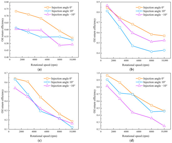
Figure 26.
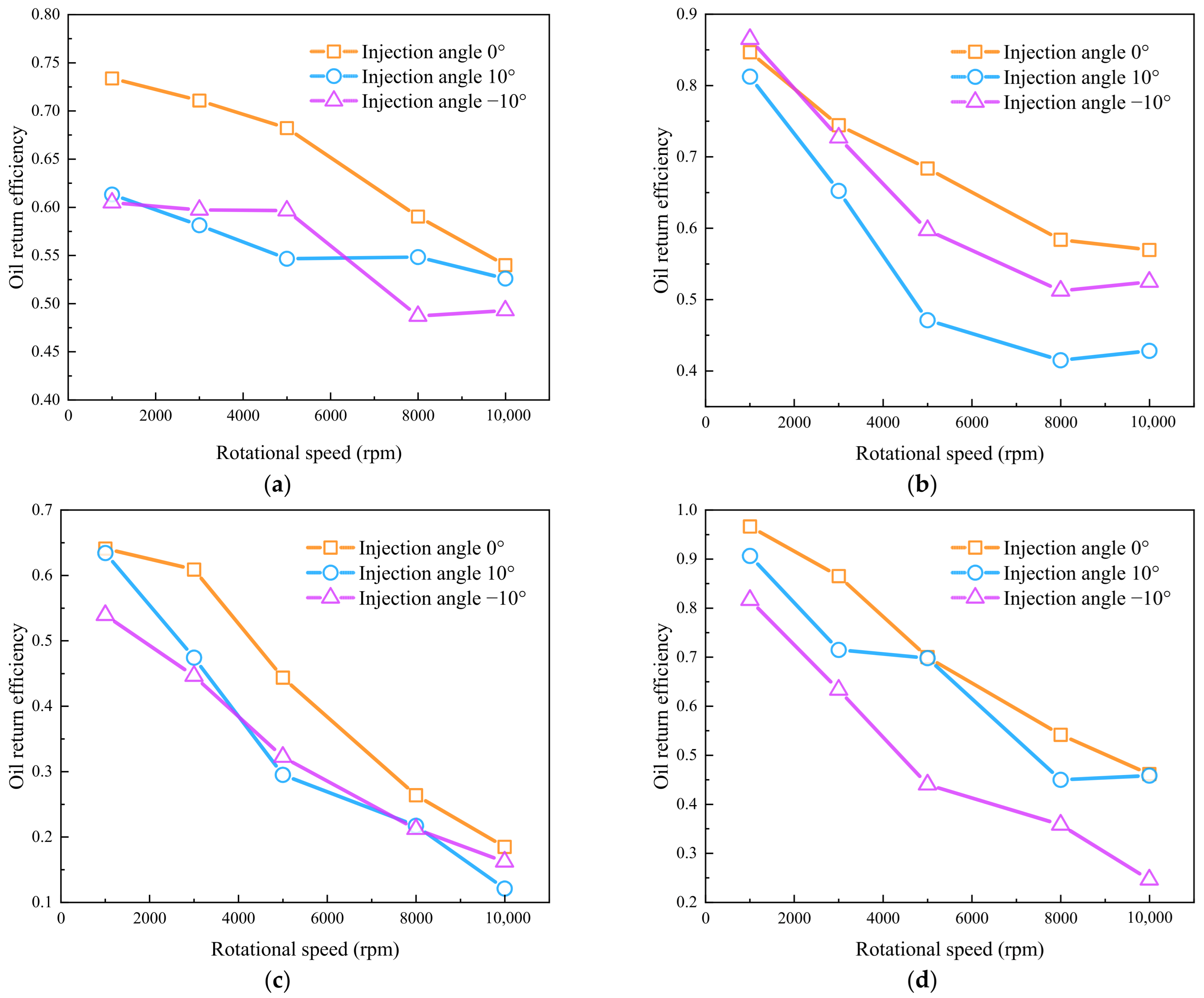
Oil return efficiency of lubricants at different incident angles: (a) Position A on the small end; (b) Position B on the small end; (c) Position C on the large end; (d) Position C on the large end.
As demonstrated in Figure 22, Figure 23, Figure 24 and Figure 25, it is evident that the maximum velocity of the oil within the bearing cavity experiences an increase (except for jet point C) when the oil jet is conducted at varying angles during the lubrication process of tapered roller bearings in comparison to positive injection. This indicates that when the incident angle is used at various pitches, more of the oil is reflected back by the rolling body, increasing velocity, rather than decelerating and flowing through the bearing and out the other end. Consequently, in the context of the oil jet lubrication of tapered roller bearings, the employment of a positive jet to enhance the lubrication effect is a recommended practice.
Figure 26 depicts the variation in oil return efficiency with rotational speed for different positions and different pitch angles of incidence. The findings indicate that the oil return efficiency of the oil-positive jet is optimal when the jet is directed at various angles. Figure 26a shows that at jet point A, the oil return efficiency of the downward and upward jets does not differ much, and the oil return efficiency of the incoming shots at each angle gradually converges with the increase in rotational speed. Figure 26b shows that at jet point B, the oil return efficiency of the upward jet is greater than that of the downward jet, and the decreasing trend of the oil return efficiency of the incoming shot at each angle with increasing rotational speed gradually slows down. Figure 26c shows that at jet point C, the oil return efficiency of the downward and upward projections does not differ much, and the oil return efficiency of the incoming projections from all angles converges as the rotational speed increases. Figure 26d shows that the oil return efficiency of the upward jet is less than that of downward jet at jet point D, where the downward jet (10°) and lubrication performance are very close to the oil-positive spray oil return efficiency.
5. Conclusions
This paper investigates the lubrication process of tapered roller bearings under oil jet lubrication. Numerical simulations were conducted to study the effects of varying speeds, injection positions, flow rates, nozzle diameters, and incidence angles on the lubrication performance of tapered roller bearings. Additionally, an experimental test bed was established for verification. The main conclusions are as follows:
- The simulation model demonstrated high accuracy, with predicted oil return efficiency values deviating by less than 10% from experimental measurements.
- The oil injection position significantly affects lubrication performance. At higher bearing speeds, injecting oil from the small end yields superior oil return efficiency compared to the large end, suggesting the practical prioritization of small-end injection when designing bearing components.
- While increasing the oil jet flow rate improves lubrication, enlarging the nozzle diameter (despite boosting efficiency) causes oil accumulation in the bearing cavity, increasing torque loss. An optimal nozzle diameter-to-angle ratio of 1 mm/0° was identified to balance these effects.
- The influence of the incidence angle depends on the injection location, with the strongest impact observed at the small end of the inner ring. Positive-angle oil jets consistently delivered the highest oil return efficiency and lubrication performance.
- In summary, directing the oil jet toward the smaller end of the bearing, appropriately increasing the nozzle flow rate, and utilizing positive jetting can significantly improve the lubrication performance of tapered roller bearings.
Author Contributions
Conceptualization, Y.D. and X.Z.; methodology, C.Y., H.W. and J.Z.; software, C.Y., H.W. and J.Z.; validation, Y.D., G.W. and X.Z.; formal analysis, X.Z.; investigation, C.Y., H.W. and J.Z.; resources, Y.D. and G.W.; data curation, C.Y., H.W. and J.Z.; writing—original draft preparation, X.Z. and G.W.; writing—review and editing, C.Y., H.W. and J.Z.; visualization, X.Z. and G.W.; supervision, X.Z. and Y.D.; project administration, Y.D. and G.W.; funding acquisition, Y.D. and G.W. All authors have read and agreed to the published version of the manuscript.
Funding
This work was supported by the National Natural Science Foundation of China (Grant No. 52475078), the National Defense Pre-Research Foundation of China (Grant No. KY-1044-2023-0451), and the Science and Technology Innovation Program of Hunan Province (Grant number 2024RC1001).
Institutional Review Board Statement
Not applicable.
Informed Consent Statement
Not applicable.
Data Availability Statement
The original contributions presented in the study are included in the article; further inquiries can be directed to the corresponding author.
Conflicts of Interest
Authors Hongmei Wu and Jianfeng Zhong were employed by the company Hunan Aviation Powerplant Research Institute, Aero Engine Corporation of China. The remaining authors declare that the research was conducted in the absence of any commercial or financial relationships that could be construed as a potential conflict of interest.
Nomenclature
| the equivalent volumetric force vector, N | |
| the volume of oil collected at the return port, Kg/s | |
| the total oil volume, Kg/s | |
| the mass source terms of air | |
| the mass source terms of lubricant | |
| roller inner diameter, mm | |
| roller internal rotating diameter, mm | |
| roller outer rotating diameter, mm | |
| the gravitational acceleration vector, m/s2 | |
| the oil return efficiency | |
| the speed of revolution of the rollers, rpm | |
| the cage speed, rpm | |
| the inner ring speed, rpm | |
| the rollers’ speed of rotation, rpm | |
| the velocity vector, m/s | |
| the air velocity vectors, m/s | |
| the lubricant velocity vectors, m/s | |
| the lubricant and air mixing viscosity, Pa.s | |
| the viscosity of air, Pa.s | |
| the viscosity of the lubricant, Pa.s | |
| the lubricant and air mixing density, Kg/m3 | |
| the densities of air, Kg/m3 | |
| the densities of lubricant, Kg/m3 | |
| the volume fraction of air | |
| the volume fraction of lubricant |
References
- Zhu, W.; Zhu, R.; Tang, X.; Lu, F.; Bai, X.; Wu, X.; Li, F. CFD-based analysis of oil and gas two-phase flow characteristics in double-row tapered roller bearings with different rib structures. Appl. Sci. 2022, 12, 1156. [Google Scholar] [CrossRef]
- Tong, V.C.; Hong, S.W. Study on the stiffness and fatigue life of tapered roller bearings with roller diameter error. Proc. Inst. Mech. Eng. Part J J. Eng. Tribol. 2017, 231, 176–188. [Google Scholar] [CrossRef]
- Maruyama, T.; Saitoh, T.; Yokouchi, A. Differences in mechanisms for fretting wear reduction between oil and grease lubrication. Tribol. Trans. 2017, 60, 497–505. [Google Scholar] [CrossRef]
- Aidarinis, J.; Missirlis, D.; Yakinthos, K.; Goulas, A. CFD modeling and LDA measurements for the air-flow in an aero engine front bearing chamber. J. Eng. Gas Turbines Power 2011, 133, 082504. [Google Scholar] [CrossRef]
- Pinel, S.I.; Signer, H.R.; Zaretsky, E.V. Comparison between oil-mist and oil-jet lubrication of high-speed, small-bore, angular-contact ball bearing. Tribol. Lubr. Technol. 2011, 67, 32. [Google Scholar] [CrossRef]
- Hager, C.H., Jr.; Doll, G.L.; Evans, R.D.; Shiller, P.J. Minimum quantity lubrication of M50/M50 and M50/Si3N4 tribological interfaces. Wear 2011, 271, 1761–1771. [Google Scholar] [CrossRef]
- Hannon, W.M. Rolling-element bearing heat transfer—Part I: Analytic model. J. Tribol. 2015, 137, 031102. [Google Scholar] [CrossRef]
- Adeniyi, A.A.; Morvan, H.P.; Simmons, K.A. A multiphase computational study of oil-air flow within the bearing sector of aeroengines. In Turbo Expo: Power for Land, Sea, and Air; American Society of Mechanical Engineers: New York, NY, USA, 2015; Volume 56734, p. V05CT15A024. [Google Scholar]
- Adeniyi, A.A.; Morvan, H.; Simmons, K. A computational fluid dynamics simulation of oil–air flow between the cage and inner race of an aero-engine bearing. J. Eng. Gas Turbines Power 2017, 139, 012506. [Google Scholar] [CrossRef]
- Zhu, D.; Chen, G.; Li, Y.; Zhang, C.; Wang, L. A 3D CFD simulation of oil spray-collection and delivery process in an aeroengine inter-shaft bearing. Chin. J. Aeronaut. 2022, 35, 366–378. [Google Scholar] [CrossRef]
- Li, M.; Wang, Y.; Chen, W.; Zhu, R. Temperature rise characteristics for angular-contact ball bearings with oil-air lubrication based on fluid-solid conjugate heat transfer. Adv. Mech. Eng. 2021, 13, 1687814021990927. [Google Scholar] [CrossRef]
- Gao, F.; Jia, W.; Li, Y.; Zhang, D.; Wang, Z. Analysis and experimental research on the fluid–solid coupled heat transfer of high-speed motorized spindle bearing under oil–air lubrication. J. Tribol. 2021, 143, 071801. [Google Scholar] [CrossRef]
- Bhat, J.A.; Harmain, G.A.; Wani, M.F.; Sehgal, R.K.; Najar, F.A. Performance enhancement of hydrodynamic thrust bearings: Investigating cooling strategies, deep recesses, and textured surfaces. Tribol. Int. 2025, 110877. [Google Scholar] [CrossRef]
- Jin, X.; Wang, Y.; Bai, Q.; Li, X.; Jiang, H.; Guo, F.; Poll, G. Cage parameters on friction within cage-pockets contacts and lubrication behaviors in ball-raceway contacts. Tribol. Int. 2025, 110747. [Google Scholar] [CrossRef]
- Wu, W.; Hu, C.; Hu, J.; Yuan, S. Jet cooling for rolling bearings: Flow visualization and temperature distribution. Appl. Therm. Eng. 2016, 105, 217–224. [Google Scholar] [CrossRef]
- Zi, X.; Chen, K.; Bai, Q.; Li, X.; Jin, X.; Wang, X.; Guo, F. The enhancement of oil delivery and bearing performance via a guiding-structured nozzle under oil–air lubrication. Lubricants 2024, 12, 60. [Google Scholar] [CrossRef]
- Hu, J.; Wu, W.; Wu, M.; Yuan, S. Numerical investigation of the air–oil two-phase flow inside an oil-jet lubricated ball bearing. Int. J. Heat Mass Transf. 2014, 68, 85–93. [Google Scholar] [CrossRef]
- Zhang, J.J.; Lu, L.M.; Zheng, Z.Y.; Gan, L.; Lv, Z.Y. Visual comparative analysis for the oil-air two-phase flow of an oil-jet lubricated roller-sliding bearing. J. Appl. Fluid Mech. 2022, 16, 179–191. [Google Scholar] [CrossRef]
- Concli, F.; Mastrone, M.N. Advanced lubrication simulations of an entire test rig: Optimization of the nozzle orientation to maximize the lubrication capability. Lubricants 2023, 11, 300. [Google Scholar] [CrossRef]
- Li, R.; Zhu, P.; Yuan, H.; Liang, H.; Wang, W. Dynamics of oil droplet impacting oil film in bearing chamber. Int. J. Mech. Sci. 2025, 302, 110555. [Google Scholar] [CrossRef]
- Kim, D.; Kim, M.; Park, J. Analytical study about effects of kerosene lubrication on slip, heat, and temperature of a cylindrical roller bearing. J. Mech. Sci. Technol. 2023, 37, 4671–4679. [Google Scholar] [CrossRef]
- Ishaq Khan, M.; Maccioni, L.; Concli, F. Trends in lubrication research on tapered roller bearings: A review by bearing type and size, lubricant, and study approach. Lubricants 2025, 13, 204. [Google Scholar] [CrossRef]
- Maccioni, L.; Chernoray, V.G.; Concli, F. Investigating lubricant behavior in a partially flooded tapered roller bearing: Validation of a multiphase CFD solver for aerated oil sump via particle image velocimetry studies and high-speed camera acquisitions. Tribol. Int. 2025, 201, 110274. [Google Scholar] [CrossRef]
- Brennen, C.E. Fundamentals of Multiphase Flow; Cambridge Ltd.: Cambridge, UK, 2005. [Google Scholar]
- Da Riva, E.; Del Col, D. Numerical simulation of laminar liquid film condensation in a horizontal circular minichannel. J. Heat Transfer 2012, 134, 051019. [Google Scholar] [CrossRef]
- Xiao, J.; Zhu, E.; Wang, G. Numerical simulation of emergency shutdown process of ring gate in hydraulic turbine runaway. J. Fluids Eng. 2012, 134, 124501. [Google Scholar] [CrossRef]
- Hu, S.; Gong, W.; Xu, X.; Liu, X. Modeling of ball bearing churning losses. Phys. Fluids 2024, 36, 083305. [Google Scholar] [CrossRef]
- Liu, J.; Ni, H.; Zhou, R.; Li, X.; Xing, Q.; Pan, G. A simulation analysis of ball bearing lubrication characteristics considering the cage clearance. J. Tribol. 2023, 145, 044301. [Google Scholar] [CrossRef]
- Wang, Z.; Wang, F.; Duan, H.; Wang, W.; Guo, R.; Yu, Q. Numerical investigation of oil–air flow inside tapered roller bearings with oil bath lubrication. J. Appl. Fluid Mech. 2023, 17, 273–283. [Google Scholar] [CrossRef]
- Dai, Y.; Tang, R.; Yu, C.; Yang, C.; Yang, D.; Zhu, X. Air–oil two-phase flow and oil penetration characteristics of angular contact ball bearing under oil jet lubrication: Numerical and experimental investigations. Phys. Fluids 2025, 37, 047133. [Google Scholar] [CrossRef]


Disclaimer/Publisher’s Note: The statements, opinions and data contained in all publications are solely those of the individual author(s) and contributor(s) and not of MDPI and/or the editor(s). MDPI and/or the editor(s) disclaim responsibility for any injury to people or property resulting from any ideas, methods, instructions or products referred to in the content. |
© 2025 by the authors. Licensee MDPI, Basel, Switzerland. This article is an open access article distributed under the terms and conditions of the Creative Commons Attribution (CC BY) license (https://creativecommons.org/licenses/by/4.0/).