Review

The Application and Development of Static Pressure Air Floating in the Field of Micro-Low-Gravity Simulation Experiments for Spacecraft

1
School of Mechanical Engineering, Tianjin University, Tianjin 300350, China
2
Tianjin Key Laboratory of Microgravity and Hypogravity Environment Simulation Technology, Tianjin Institute of Aerospace Mechanical and Electrical Equipment, Tianjin 300301, China
3
College of Mechanical and Vehicle Engineering, Hunan University, Changsha 410082, China
4
Institute of Spacecraft System Engineering, Beijing 100190, China
5
Beijing Institute of Control Engineering, Beijing 100190, China
*
Author to whom correspondence should be addressed.
Lubricants 2025, 13(6), 258; https://doi.org/10.3390/lubricants13060258
Submission received: 17 April 2025 / Revised: 5 June 2025 / Accepted: 9 June 2025 / Published: 11 June 2025
(This article belongs to the Special Issue Space Tribology)

Abstract

The force conditions experienced by spacecraft and astronauts in space are vastly different from those in Earth’s gravitational environment, hence it is necessary to conduct adequate micro-low-gravity environment simulation tests on the ground before launch. In this paper, an overview is provided of the current status of micro-low-gravity simulation test technology for spacecraft based on hydrostatic air-bearing. The paper systematically organizes the application of hydrostatic air-bearing technology in micro-low-gravity simulation tests, such as the deployment of space mechanisms, spacecraft GNC (Guidance, Navigation, and Control), on-orbit operations of space manipulators, and astronaut training. It summarizes the principles of air-flotation micro-low-gravity simulation technology in different scenarios and distills suitable solutions for various requirements. Finally, the paper looks forward to the development trends of air-flotation micro-low-gravity simulation test technology and proposes key technical challenges that need to be overcome in aerostatic bearing.

1. Introduction

As manned lunar landings, deep space exploration, and on-orbit servicing missions continue to evolve, human activities in space are becoming increasingly frequent and the tasks more intricate. Micro-low gravity is a defining characteristic of the space mechanical environment, presenting unique demands and challenges for spacecraft structural and mechanical design, as well as Guidance, Navigation, and Control (GNC) systems. The significant disparity between terrestrial and space mechanical environments necessitates a series of functional and performance tests for spacecraft in simulated micro-low-gravity conditions on the ground. These tests are crucial for effectively identifying risks associated with on-orbit motion, thoroughly validating spacecraft functionality, enhancing launch reliability, reducing launch costs and risks, and ensuring the successful execution of on-orbit missions [1,2]. Consequently, pre-launch ground-based micro-low-gravity testing for spacecraft and astronauts is a vital technical procedure, and research into spacecraft ground testing technologies based on micro-low-gravity simulation is essential for the success of space missions.
The gas-floating method is the most widely applied technique in the field of micro-low-gravity simulation testing for spacecraft [3]. The primary principle involves suspending the simulated flying vehicle through hydrostatic gas bearings, where the gas buoyancy force counterbalances the object’s gravitational force, enabling near-frictionless free motion, and thus, high-fidelity simulation of the mechanical environment in which spacecraft float in space. Due to its high simulation accuracy, low development costs, minimal friction, extended test durations, and minimal requirements for the volume and weight of test articles [4,5], the gas-floating method is extensively utilized in a variety of microgravity simulation domains, including the deployment tests of space mechanisms [6,7], GNC control tests for spacecraft [8,9], operational tests for space robotic arms on-orbit [10,11], and astronaut training [12,13], as depicted in Figure 1. This method plays an irreplaceable role in the development process of space missions [14,15].
This paper addresses various application scenarios and provides a comprehensive review of the technical solutions and principles behind the use of hydrostatic gas bearings for micro-low-gravity simulation in space mechanisms, spacecraft Guidance, Navigation, and Control (GNC) systems, on-orbit operations of space manipulators, and astronaut training. It analyzes the current technological characteristics and research issues associated with these applications and concludes with an outlook on the technical challenges and development trends of hydrostatic gas bearings in future micro-low-gravity testing for spacecraft.

2. Application in the Deployment Mechanisms Micro-Low-Gravity Simulation Experiments

The working principle of aerostatic bearings involves introducing pressurized gas from an external source into the orifice. After passing through the restrictor, the high-pressure gas undergoes a pressure drop due to expansion and then enters the bearing clearance to form a lubricating air film, thereby enabling the bearing to support loads [16], as shown in Figure 2. A notable feature of aerostatic bearings is the requirement for an external supply of pressurized gas. The restrictor, a key component of these bearings, comes in various types, including orifice restrictors, conical restrictors, parallel restrictors, and porous media restrictors [17,18].
The unsteady Reynolds equation for compressible fluid is the fundamental equation for calculating the gas pressure distribution within the bearing clearance,
x ρ h 3 μ p x + y ρ h 3 μ p y = 6 U x ρ h + 2 t ρ h
where μ is the dynamic viscosity of the gas, ρ is the density, h is the length in the gap direction, and U is the velocity in the x-direction.
In aerostatic bearing design, it is crucial to fully assess performance aspects such as load capacity, stiffness, flow rate, and stability. The distribution of gas pressure p within the bearing clearance is a key indicator of bearing performance. By adapting the bearing configuration to Equation (1), the pressure distribution can be determined [19,20].
Deployable space mechanisms refer to spacecraft mechanisms that can be folded into a compact shape and unfolded into a larger predetermined form. They typically feature large dimensions, high folding ratios, high rigidity, and lightweight design. Typical products include solar wings, deployable antennas, and deployable arms. The successful deployment of these mechanisms is often a critical factor in the success or failure of a spacecraft. During the deployment process in orbit, factors such as flexibility and gaps in the deployment mechanisms, as well as the micro-low-gravity environment, significantly affect the functionality and performance of the deployment. Ground-based micro-low-gravity tests are necessary to verify the effectiveness of the deployment mechanisms in orbit. The resistance torque (force) introduced by the test equipment should be less than the driving torque (force) margin of the deployment components under the corresponding environmental conditions to avoid deployment anomalies caused by excessive friction in the ground test system. Hydrostatic air bearings, due to their minimal friction torque (force) advantage, are widely used in the deployment tests of space mechanisms [21,22]. Structurally, they mainly include three types [23]: planar thrust bearings, radial rolling bearings, and linear sliding bearings, as shown in Figure 3. The radial rolling bearings are specifically divided into two conditions: radial load bearing and axial load bearing. In practical engineering applications, different combinations of air bearings are used to meet the deployment test requirements of space mechanisms in different dimensions. Additionally, for economic considerations, a combination of air bearings and mechanical bearings is often employed.

2.1. One-Dimensional Linear Motion Mechanism

Sleeve-type extension rods, disc compression rods, hinged rods, and other rod-like deployment mechanisms, as well as mechanisms where the center of mass (or suspension point) moves in a straight line, are considered one-dimensional linear motion [24]. For flexible deployment mechanisms, an aerostatic guide rail and slider suspension and an unloading method can be used. When the mechanism is sufficiently rigid, a planar thrust aerostatic bearing support and unloading method can also be employed to achieve one-dimensional deployment testing, as shown in Figure 4.
Figure 5a depicts the ADAM (Able Deployable Articulated Mast) arm, which is entirely composed of rigid rods and is driven by a sleeve mechanism for deployment. It utilizes a one-dimensional suspension deployment test method [25]. The deployment and retraction of the sleeve-type arm are both achieved through telescoping sleeves. Figure 5b shows a sleeve-type arm developed by Astro Aerospace [26]. The telescoping sleeve can take the form of a cylindrical tube or a tubular truss structure, with the diameter decreasing from the deployment base to the deployment end, allowing it to be folded into the largest sleeve at the base. Its deployment process employs a one-dimensional support deployment method.

2.2. Two-Dimensional Planar Motion Mechanism

The trajectory of the moving parts of mechanisms such as parabolic antennas, oscillating mechanisms, flat-panel radar antennas, ribbed mesh antennas, and circular solar panels is a two-dimensional curve, and the suspension points need to move in a two-dimensional plane. Typical design forms for the deployment of suspension mechanisms include the polar coordinate swing arm with horizontal guide rail slider type (Figure 6a), the vertical air bearing wheel with horizontal guide rail slider type (Figure 6b), and the XY dual guide rail slider type (Figure 6c). Hydrostatic air bearings are widely used in the deployment tests of two-dimensional planar motion mechanisms. Figure 7b shows the two-dimensional deployment mechanism micro-low-gravity suspension test system developed by the Tianjin Institute of Aerospace Mechanical and Electrical Equipment.
The Netherlands-based Fokker Space company has conducted similar application research (Figure 7a), where they utilized air bearings to modify the traditional roller trolley suspension gravity compensation device, achieving low-resistance operation (with a longitudinal resistance coefficient of 1% and a lateral resistance coefficient of 0.1%) of the suspension point in both horizontal and vertical directions [27]. However, the rated load capacity of a single suspension point in the gravity compensation device modified by Fokker Space is only 100 N, and the operating range of the suspension point is also relatively limited. The China Academy of Space Technology has carried out solar panel deployment tests (Figure 7b) [28].
For deployment mechanisms with high rigidity, such as rigid solar panels and radar antennas, an engineering solution that can be employed is a planar air cushion support system. This system enables micro-low-gravity deployment tests within a planar environment, as illustrated in Figure 8. The deployment test system comprises an air-bearing support platform, planar thrust bearings, and a gas supply system, among other components. The air suspension assembly not only provides a zero-gravity simulation environment for the deployment mechanism but also facilitates height fine-tuning, load measurement, transmission, and display. It exhibits a high degree of adaptability to the planarity of the air-bearing platform surface. The two-dimensional deployment test system based on planar thrust bearings is compact, offers excellent repeatability of test results, and features high system reliability and zero-gravity simulation accuracy. Additionally, it is convenient for installation and disassembly, making it widely applicable.
The Canadian Space Agency and NASA jointly developed the RADARSAT-II satellite system, which conducted ground zero-gravity simulation tests for the SAR antenna (Figure 9b). The system consists of a support platform, air bearings, and a gas supply system, among other components. It provides a zero-gravity simulation environment for antenna deployment while also offering height fine-tuning and load measurement capabilities, demonstrating high adaptability [29]. This system significantly reduces the frictional forces caused by gravity, achieving excellent test results in a two-dimensional plane.

2.3. Three-Dimensional Spatial Motion Mechanism

The trajectories of the end-effectors of serial mechanisms such as antenna deployment arms and two-dimensional secondary solar panel arrays are spatial curves, necessitating three-dimensional spatial motion of the suspension points. A typical design form is “polar coordinate swing arm + horizontal guide rail + vertical counterweight”, as shown in Figure 10. In practical engineering applications, for economic considerations, a combination of “air bearings + mechanical bearings” can also be employed.

3. Microgravity Simulation Testing for Spacecraft GNC

The GNC (Guidance, Navigation, and Control) control system of a spacecraft is the core and critical subsystem for achieving tasks such as attitude control, orbital maneuvering, and rendezvous and docking [30], as illustrated in Figure 11. Ground-based micro-low-gravity simulation and testing are primarily categorized into three major types: mathematical simulation, semi-physical simulation testing, and full-physical simulation testing. Full-physical simulation testing based on aerostatic bearings involves using an air-bearing platform to simulate the spacecraft body as the control object, with the control system employing actual spacecraft control components for the simulation test.
The use of air-bearing platforms as a means of simulating spacecraft attitude control systems began almost concurrently with the development of spacecraft. For example, the early American Tiros satellite conducted nutation damping tests using an air-bearing platform [31]. In early 1968, China used a three-axis air-bearing platform for the antenna deployment test of the Dong Fang Hong I satellite. Since the attitude motion speed of spacecraft is very low, ground-based physical simulation of spacecraft attitude motion mainly considers achieving a weightless environment. The air-bearing platform relies on a layer of compressed air between the air bearing and the bearing housing to suspend the simulated platform body, thereby achieving a weightless and frictionless relative motion condition, simulating the mechanical environment of spacecraft in outer space where the disturbance torques are minimal. Compared to semi-physical simulation of spacecraft control systems, full-physical simulation does not require a simulation computer; the spacecraft dynamics are entirely simulated by the air-bearing platform. In this way, full-physical simulation can more realistically simulate the spacecraft’s dynamics, momentum exchange, and momentum coupling in space on the ground, and identify potential issues with the actual model. Currently, air-bearing platforms are mainly divided into two categories: fixed air-bearing platforms [32,33] and mobile air-bearing platforms [34,35].

3.1. Attitude Control Experiments with Fixed Air-Bearing Platforms

Attitude control is a crucial component for ensuring the normal operation of satellites, exemplified by remote sensing, navigation, and communication satellites (Figure 12). Throughout their full-service life after orbit insertion, in addition to maintaining the orbit, real-time attitude control is necessary to accomplish core tasks such as high-resolution Earth remote sensing and signal transmission.
The attitude control experiment micro-low-gravity simulation methods mainly include two types: single-axis air-bearing tables and three-axis air-bearing tables, both of which are fixed experimental systems, as shown in Figure 13. The air-bearing turntable, as the main embodiment of the dynamic physical model, has key technical indicators of load capacity and comprehensive disturbance torque. Load capacity refers to the total mass stably suspended by the air film, including the mass of the aerostatic bearing rotor, that is, all the masses stably levitated by the air film are included in the mass characteristics of the overall dynamic model of the system. Comprehensive disturbance torque refers to the subtle differences in gas flow caused by factors such as the roughness of the aerostatic bearing, sphericity/cylindricity error, orifice diameter error, and positional asymmetry deviation, which are macroscopically manifested as comprehensive disturbance torque, indicating the manufacturing quality of the aerostatic bearing. As a dynamic simulation system, the simulation accuracy of the air-bearing table is affected not only by the comprehensive disturbance torque of the bearing but also by factors such as the change in the center of mass of the installed instrument platform and wind resistance after the installation of the instrument platform, which will affect the experimental accuracy and superpose with the bearing’s comprehensive disturbance torque to form the total resistance torque. Therefore, it is necessary to control the overall dynamic simulation accuracy indicators to ensure the experimental requirements.
The dynamic simulation accuracy can be expressed as
P ac = T min T d T min × 100 %
In the formula, Pac is the dynamic simulation accuracy, Tmin is the minimum driving torque, and Td is the resistance torque.

3.1.1. Single-Axis Air-Bearing Platform

A single-axis air-bearing platform refers to an air-floating device that can only rotate around the axis perpendicular to the supporting surface. It consists of aerostatic bearings, an instrument platform, equipment on the platform, a fixed base, an angle measuring device, air supply pipelines, etc. The typical structure is shown in Figure 14. According to the spacecraft attitude dynamics equations, the motion of a spacecraft around its pitch axis is approximately independent. Therefore, the single-axis air-bearing platform is mainly used to simulate the motion of the spacecraft’s pitch axis. The gyroscope measures the angular velocity of the platform, and the onboard computer processes it in real time, outputting corresponding control instructions and control quantities. The control torque of the actuator, such as the torque gyroscope, can be directly applied to the single-axis air-bearing platform for attitude control single-channel simulation, or unit testing of the executive components. It is suitable for three-axis stabilized spacecraft using reaction wheels and can also be used to study the performance of flexible structures and the control of flexible vibration suppression [36].
Single-axis air-bearing platforms are categorized by their load-bearing capacities. Generally, those capable of supporting over 1000 kg are considered large systems, used for testing and validation of large spacecraft, whereas those supporting between 100 to 200 kg are small systems, used for certain dynamic testing and validation. Regardless of size, their main configurations are similar, but due to different simulation test requirements and objectives, the simulation control systems involved vary, leading to differences in the dynamic performance of the single-axis air-bearing platforms.
The disturbing torque of a single-axis air-bearing turntable is less than 10−3 Nm within a 360° rotation of the platform. When tests require a larger moment of inertia, a typical design solution involves combining a single-axis air-bearing platform with a planar air-cushion support. This setup uses the planar air cushion to levitate remote weights, simulates satellite flexible appendages with trusses, and connects them to the single-axis platform to form an air-bearing single-axis test platform with a very large moment of inertia [14]. The principle of implementation is shown in Figure 15.
Figure 16a depicts a typical single-axis air-bearing platform developed by Northwestern Polytechnical University, used for full-physical simulation tests of satellite attitude control with flexible appendages [37]. The Tianjin Institute of Aerospace Mechanical and Electrical Equipment and the Beijing Institute of Control Engineering have jointly developed an ultra-high inertia micro-low-gravity simulation test system for spacecraft using the single-axis air-bearing platform, which is applied to the control system verification tests of China’s space station. This is currently the domestic single-channel test system with the largest inertia (Figure 16b) [38].

3.1.2. Triaxial Air-Bearing Platform

The three-axis air-bearing table, with its core components being air-bearing ball bearings, forms an air film between the sphere and the socket, offering three degrees of rotational freedom. This enables the simulation of yaw, roll, and pitch, the three attitude degrees of freedom, making it a key piece of equipment in a three-channel full-physical simulation test system. It is composed of air-bearing ball bearings, an instrument platform, on-platform equipment, angle measurement devices, a fixed base, a lifting mechanism, and an air source.
Depending on the design, the three-axis air-bearing table can be categorized into three types: desktop-style, umbrella-style, and dumbbell-style platforms, with their typical structures shown in Figure 17. The desktop and umbrella configurations can achieve 0 to 360° motion around the yaw axis, while the pitch and roll axes can only achieve motion within a certain range [39,40]. The dumbbell configuration can achieve 0 to 360° motion around both the yaw and roll axes, with the pitch axis capable of motion within a certain range [41,42].
Figure 18 illustrates a typical three-axis air-bearing table. The comprehensive disturbing torque of the platform is a key performance indicator of the system. The disturbing torque acting on the vertical axis of the platform is primarily due to eddy current torque, which is approximately 4 × 10⁻⁴ Nm, and this needs to be ensured by improving the machining quality of the air-bearing. The disturbing torques on the two horizontal axes depend on the static balance of the platform and are closely related to the overall mass of the attitude platform. Adjustments need to be made through balancing techniques to coincide with the centroid of the air-floating sphere, reducing gravitational eccentric disturbing torques, and improving the accuracy of dynamic simulation. These torques typically fall within the order of 10−3 Nm, with a maximum not exceeding the order of 10−2 Nm. The three-axis air-bearing table is mainly used for precision tests of spacecraft attitude control. It is the most widely used equipment in the field of satellite attitude control testing [43,44], covering applications for micro and nano satellites [45,46], medium and small satellites, and heavy satellites [47,48], as shown in Figure 19.
Figure 19c shows the OAO three-axis air-bearing table developed by Grumman Corporation [49], with a load capacity of up to 9 tons. The large-scale three-axis air-bearing table jointly developed by the Tianjin Institute of Aerospace Mechanical and Electrical Equipment and the Beijing Institute of Control Engineering has a load capacity of over 10 tons (Figure 19d), making it currently the heaviest air-bearing table for attitude control testing within its field.

3.2. Attitude and Orbit Control Experiments with Movable Air-Floating Stages

The most commonly used approach in attitude and orbit control experiments is the multi-degree-of-freedom air-floating satellite simulator [50]. Depending on the number of simulated degrees of freedom, multi-degree-of-freedom satellite simulators can be categorized into three types: three-degree-of-freedom [51], five-degree-of-freedom [52], and six-degree-of-freedom [53] air-floating satellite simulators. Based on the differences in simulated gravitational environments, there are two types of experimental conditions: zero-gravity simulation and low-gravity simulation.

3.2.1. Three-Degree-of-Freedom Air-Floating Platform

The three-degree-of-freedom air-floating platform achieves frictionless motion in three degrees of freedom—two-dimensional translation in the XY plane and rotation about the Z-axis—by forming an air film through the cooperation of air cushions and the floating platform, which generates a supporting force to compensate for the platform’s gravity, as shown in Figure 20. It is composed of a planar thrust bearing, a movable base, a translating platform, process equipment on the platform, a high-pressure gas bottle assembly, and cold gas thrusters. The platform body can move freely on a granite platform and rotate freely around its own axis. It is mainly used for zero-gravity simulation in a two-dimensional plane. The key technical indicators include the total mass of the platform body, the moment of inertia about the vertical axis after loading components and counterweights on the platform body, the maximum and minimum horizontal acceleration of the platform body, the maximum and minimum angular acceleration of the platform body’s rotation, the rotational disturbance torque of the platform body, and the working time.
The planar three-degree-of-freedom air-floating platform offers excellent ground demonstration and verification capabilities for validating spacecraft formation flying strategies, orbiting, target approach, and two-dimensional capture missions, making it a cost-effective experimental solution [54,55]. Figure 21a illustrates how the Massachusetts Institute of Technology (MIT) used a planar three-degree-of-freedom air-floating platform to conduct validation analysis on the tethered dynamics of SPHERES (Synchronized Position Hold Engage Reorient Experimental Satellites) satellites [56]. The SPHERES program aims to launch multiple volleyball-sized satellites into space that maintain precise relative positions to form a large space telescope for detecting exoplanets around other stars. To simulate formation flying among microsatellites and test control algorithms in a ground environment, MIT developed several three-degree-of-freedom air-floating platforms. These platforms levitate on an air cushion generated by high-pressure CO2 above the working surface, enabling two-dimensional translational motion and rotation about a vertical axis [57]. The Naval Postgraduate School utilized the POSEIDYN air-floating spacecraft simulator testbed in the Spacecraft Robotics Laboratory to conduct research on autonomous rendezvous and spacecraft self-assembly [58,59], as depicted in Figure 21b. The Harbin Institute of Technology designed a ground simulation test platform for spacecraft swarm experiments [60], as illustrated in Figure 21c. Control algorithms were designed and verified using a three-degree-of-freedom air-floating spacecraft simulation robot, achieving angular control accuracy of 0.5° and positional accuracy of 10 mm at a control frequency of 10 Hz. The National University of Defense Technology developed a ground test system for small satellite synthetic mission demonstration [61], as shown in Figure 21d. This system consists of five parts: the test platform, small satellite simulator, monitoring control system, data acquisition and simulation system, and display system. It can simulate the three-degree-of-freedom motion of small satellites using a smooth granite platform and an air-bearing system.

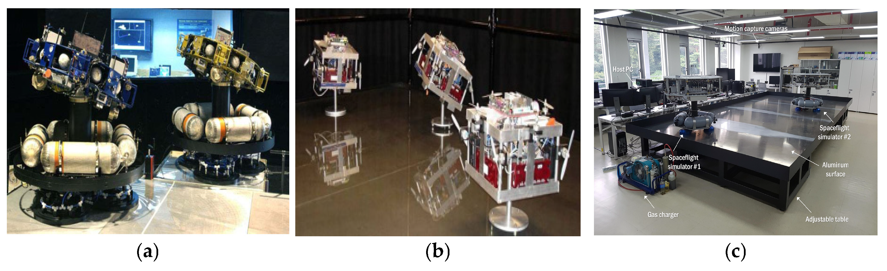
3.2.2. Five/Six-Degree-of-Freedom Air-Floating Platform

By integrating planar aerostatic bearings, spherical aerostatic bearings, and vertical zero-gravity technology, it is possible to achieve five- and six-degree-of-freedom (DOF) simulations for spacecraft [62]. The five-DOF simulation includes planar motion degrees of freedom and three-axis attitude degrees of freedom [63], as shown in Figure 22a; the six-DOF simulation encompasses planar, three-axis attitude, and vertical degrees of freedom [64], as depicted in Figure 22b. These two types of satellite simulators are suitable for more complex three-dimensional microgravity simulation experiments, such as rendezvous and docking, spatial three-dimensional capture, and attachment to small celestial bodies [65,66].
The five-/six-degree-of-freedom satellite simulator is structurally divided into an attitude platform and a translation platform, as shown in Figure 23. The basic design principles are as follows: the total mass of the attitude platform and the translation platform should equivalently simulate the total mass of the satellite; the inertia of the attitude platform should equivalently simulate the inertia of the satellite. Among these, priority should be given to ensuring that the mass equivalence criterion is met.
M atti + M move = M satellite J atti = J satellite
In the equation, Matti is the mass of the attitude platform, Mmove is the mass of the translation platform, and Msatellite is the equivalent total mass of the simulated satellite. Jatti is the inertia of the attitude platform and Jsatellite is the inertia of the simulated satellite.
In accordance with the varying requirements for simulating gravitational environments during spacecraft testing, two types of test conditions can be distinguished: zero-gravity simulation and low-gravity simulation, as shown in Figure 24. Zero-gravity simulation is achieved using a horizontal air-bearing platform, while low-gravity simulation employs an inclined air-bearing platform, where the angle of inclination, denoted as α, can be expressed as follows:
α = arcsin g simu g groud
To search for Earth-like planets and investigate formation flying and space telescope arrays, NASA has developed an advanced air-bearing simulation test system, which includes multiple simulators with five and six degrees of freedom [67,68], as shown in Figure 25a. The University of Southampton has developed a five-degree-of-freedom air-bearing simulation test system for formation flying research [69,70], as depicted in Figure 25b. The Astrodynamics and Control Laboratory (ACL) at Yonsei University has developed the ASTERIX (Autonomous Spacecraft Test Environment for Rendezvous in ProXimity) facility [71], as shown in Figure 25c. The Harbin Institute of Technology, in collaboration with the China Academy of Space Technology, has developed a five-degree-of-freedom air-bearing platform for simulating rendezvous and docking experiments [72], as illustrated in Figure 25d. The Shanghai Academy of Spaceflight Technology has developed a docking simulation test bench [73], as shown in Figure 25e.
On this basis, several research organizations have applied hydrostatic air-bearing technology to extraterrestrial probe landing and roving ground testing systems, as illustrated in Figure 26. The Polish Centre for Space Research, in collaboration with the European Space Agency (ESA), has designed a study utilizing the air-bearing method to develop a novel sampling device named PACKMOON, which is specifically tailored for low-gravity celestial environments and intended for the collection of lunar soil samples [74], as shown in Figure 26a. The simulation of landing cushioning for extraterrestrial bodies represents one of the most recent applications of planar air-bearing microgravity simulators [58], as depicted in Figure 26b. When examining the landing dynamics of probes, planar air bearings, in conjunction with a granite platform inclined at an angle, offer an ideal low-gravity simulation environment.

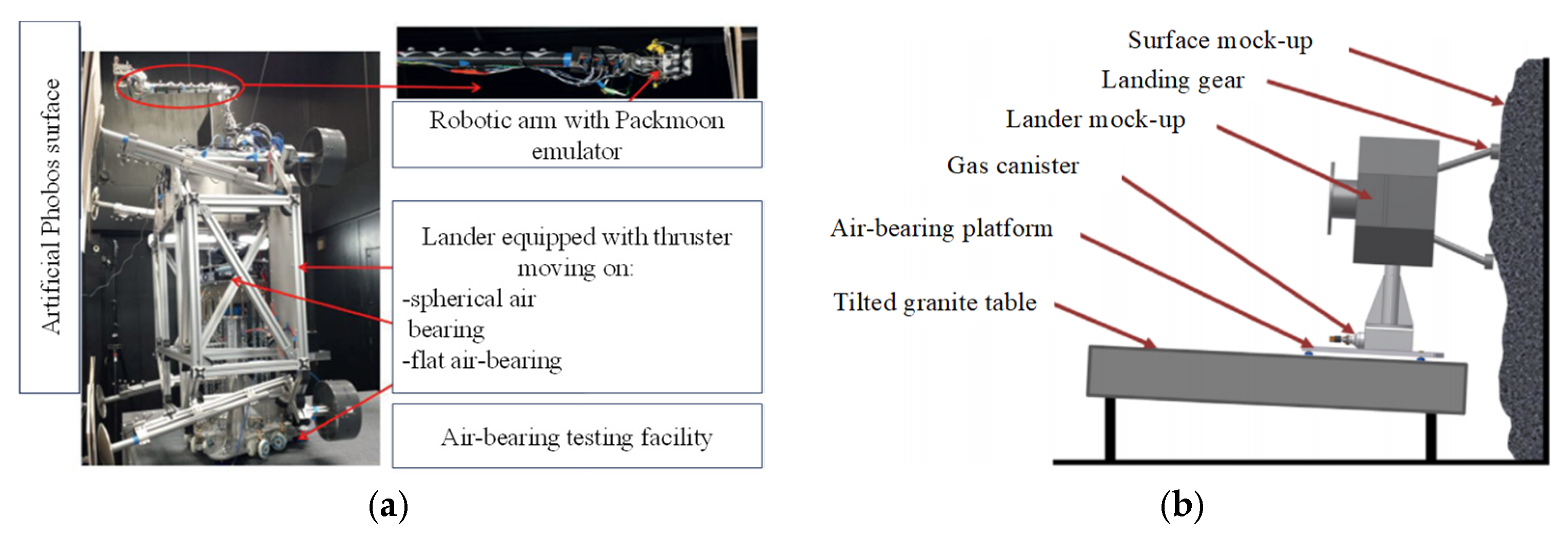
4. On-Orbit Operation Microgravity Simulation Experiments for Space Manipulator Arms

Space robotic arms serve as crucial maintenance tools on spacecraft, capable of performing various tasks such as deploying and retrieving satellites, as well as assembling and repairing space stations in orbit, as shown in Figure 27. They can also act as auxiliary tools for astronauts during extravehicular activities (EVAs), and even replace some of the astronauts’ tasks, significantly enhancing the capabilities and safety of EVAs [75]. With the advancement of space technology, countries such as Canada, Russia, Germany, and Japan have successively mastered space robotic arm technology, which has been applied to numerous spacecraft including satellites, space shuttles, and the International Space Station (ISS). It represents a key focus of research for intelligent development in the future space exploration domain. The air-bearing method compensates for the gravitational effects on space robotic arms/robots through hydrostatic aerostatic bearings, characterized by short construction periods, low costs, and ease of implementation. Regarding space robots, they can be categorized into three types: fixed-base space robots, free-flying space robots, and free-floating space robots [76,77]. That is to say, the spacecraft’s attitude and position are controlled, attitude is controlled but position is not controlled, and both attitude and position are not controlled.
Accordingly, based on the practical requirements of various space missions, microgravity testing of space robotic arm operations in orbit can be categorized, in terms of implementation, into fixed-base robotic arm air-bearing tests (Figure 28a) and coupled satellite-plus-robotic arm air-bearing tests (Figure 28b) [78,79].

4.1. Pneumatic Levitation Testing of the Robotic Arm Manipulator

For fixed-base space robots, the position and attitude of the satellite itself are controlled and can be approximated as a stationary base. These types of robotic arms are relatively large in scale, and ground testing primarily focuses on verifying the mechanical and operational performance of the robotic arm itself. The Canadian Space Station Remote Manipulator System (SSRMS) and Special Purpose Dexterous Manipulator (SPDM) robotic arms [80] (Figure 29a), the European Space Agency’s European Robotic Arm (ERA) [81] (Figure 29b), the Japanese Experiment Module Remote Manipulator System (JEMRMS) [82] (Figure 29c), and the ground testing system for China’s space station robotic arm [83] (Figure 29d) all utilize fixed-base pneumatic levitation testing for robotic arms. The system supports the robotic arm’s own gravity through multiple planar thrust bearings, achieving a gravity-free environment within the plane, which can provide comprehensive overall performance testing before the robotic arm performs on-orbit manipulations.
During the development phase of China’s space station robotic arm, a ground zero-gravity simulation system based on planar thrust bearings was also employed to simulate the two degrees of freedom planar motion and target capture motion of the space robotic arm in space. In the meantime, the Tianjin Institute of Aerospace Mechanical and Electrical Equipment and Harbin Institute of Technology have further conducted research around three-dimensional micro-low-gravity simulation testing technology, endowing the robotic arm with a certain range of three-dimensional motion testing capabilities, providing new ideas for subsequent complex operation-type tests on orbit [84].

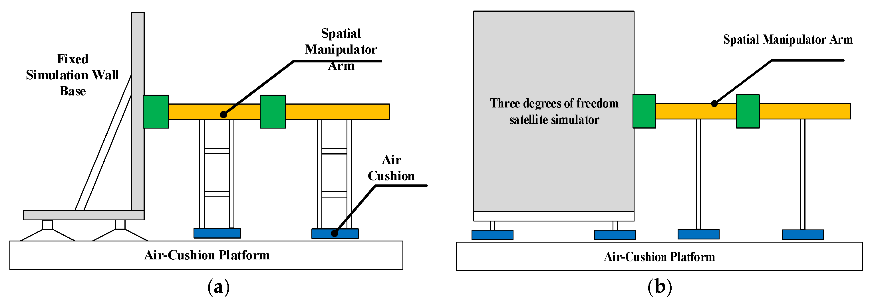
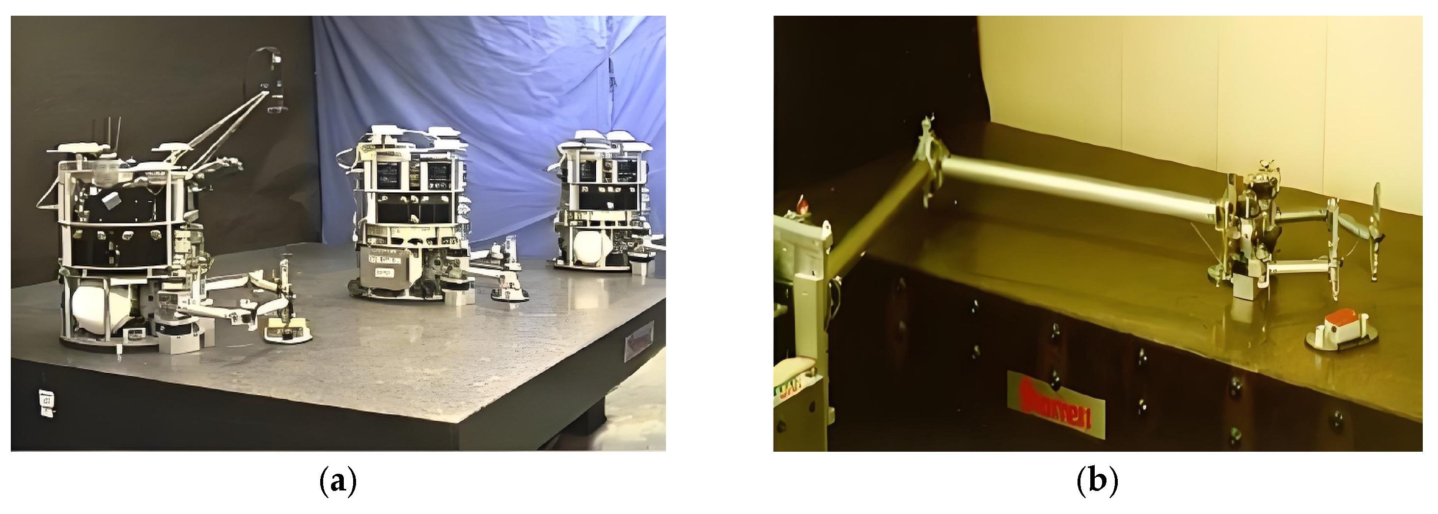
4.2. Coupled Satellite-Robotic Arm Pneumatic Levitation Testing

The coupled satellite–robotic arm pneumatic levitation testing is currently primarily implemented based on a three-degree-of-freedom air-bearing platform combined with planar air-bearing supports. This method is only applicable to experiments involving floating-base spatial robots within a two-dimensional plane.
The Macro/Micro Manipulator developed by Stanford University’s Space Robotics Laboratory [85,86] consists of two 1.5-m long macro robotic arms and a set of micro robotic arms, as shown in Figure 30a,b. The entire system floats on a granite platform via air bearings, with DC motors equipped with encoders for detection at the shoulder and elbow joints, and a vision system for end-point tracking. Similarly, the Naval Postgraduate School and the Polish Academy of Sciences have both utilized planar air-bearing methods to conduct two-dimensional experiments on floating-base spatial robots [87,88], as shown in Figure 30c,d, respectively.

5. Application of Aerostatic Bearings in Micro-Low-Gravity Simulation for Astronaut Training

With the ongoing development of the International Space Station and manned space activities, astronauts are playing an increasingly vital role in the utilization and exploration of the space environment. In conducting scientific experiments, assembling and repairing spacecraft, controlling spacecraft, and space exploration, humans possess distinct advantages that automated technology cannot match. At the same time, human involvement significantly increases the complexity of the system. Since the unique space environment has a substantial impact on astronauts’ physiological functions, operational capabilities, and behavior, tasks that are familiar and easy on Earth become extremely challenging. Consequently, ground-based training for astronauts to simulate on-orbit operations is of paramount importance for the successful execution of subsequent space missions. The Precision Air-Bearing Facility (PABF) developed by NASA’s Johnson Space Center provides two-dimensional microgravity simulation motion through a 32-foot by 24-foot (10 m by 7 m) metal platform, as shown in Figure 31. This facility plays a crucial role in engineering experiments and astronaut crew training, particularly for skills related to the movement of large equipment [89,90].

6. Trends in the Development of Pneumatic Levitation-Based Microgravity Simulation Technology

It is evident that aerostatic bearing technology holds a significant position in the field of full-physical simulation of spacecraft. To meet the urgent needs of space engineering and promote the rapid development of micro-low-gravity ground testing technology for spacecraft, this paper proposes the following prospects for research on microgravity simulation methods based on hydrostatic air-bearing technology:

6.1. Future Demand Challenges

(1)
Ultra-large spacecraft mechanisms: Future ultra-large spacecraft may reach sizes of hundreds of meters or even kilometers, presenting high aspect ratios and large dimensions, which bring technical challenges such as spatial scale adaptability and complex dynamics for ground micro-low-gravity environment simulation systems. Currently, the China Academy of Space Technology has built the world’s largest high-stiffness supported air-bearing platform (30 m × 40 m) [91], which still struggles to meet the micro-low-gravity simulation testing needs for large-scale spacecraft mechanisms at the hundred-meter level. Therefore, it is necessary to develop a new type of movable microgravity simulation platform to meet the ground dynamic testing requirements of ultra-large spacecraft mechanisms.
(2)
Heavy-load, high-precision, and high-stability aerostatic levitation: Currently, micro-low-gravity simulation and testing based on aerostatic levitation can cover a load capacity ranging from kilograms to tons [92,93,94]. The Beijing Institute of Control Engineering and the Tianjin Institute of Aerospace Mechanical and Electrical Equipment have developed large three-axis aerostatic platforms supported by spherical aerostatic bearings, with a load capacity of 10 tons and a composite disturbance torque of 10−4 Nm. With the advancement of space engineering projects such as on-orbit servicing and maintenance, and deep-space exploration, future spacecraft payloads are expected to reach tens to hundreds of tons [95], while aerostatic bearing technology also faces higher demands for low disturbance torque and high stability. Optimizing gas flow within limited dimensions, suppressing aerostatic vibration, and maximizing the effective aerostatic bearing area and gas film pressure is key to the design of heavy-load, high-performance aerostatic bearings.
(3)
Extreme service environments: The current operating environment for air bearings is generally at normal temperature and pressure. To meet more realistic service environment simulation requirements, it is necessary to further develop the hydrostatic air-bearing technology for high and low temperature and vacuum environments.

6.2. Vibration Suppression Mechanism Analysis

In aerostatic bearings, vibration issues are linked to multiple factors, such as flow field characteristics, mechanical properties, and environmental factors, which make it challenging to accurately reveal the mechanisms. Over the years, scholars have conducted extensive research on the vibration mechanisms of aerostatic bearing from various aspects, including computational models, pressure equalization chamber structures, and pneumatic hammer mechanism, and have achieved considerable research results [96,97,98,99,100]. Facing the future demands for high-stability and high-reliability spacecraft microgravity simulation tests under harsh conditions such as vacuum and extreme temperatures, there are still several areas that need further investigation and improvement regarding aerostatic bearing:
(1)
Vibration mechanism under multi-field coupling: In response to the demands for simulating complex aerospace conditions, there is a growing need to emphasize the application of multi-physics coupling analysis methods, such as the integration of fluid dynamics with structural mechanics and thermodynamics. During preliminary experiments on the dynamic characteristics of aerostatic bearings under vacuum conditions, it was observed that aerostatic bearings exhibited significantly intense self-excited vibrations in a vacuum environment [101]. With the advancement of space technology, the application of static pressure air bearings in vacuum environments is set to increase. Looking ahead to the testing requirements for future vacuum microgravity environments, it is essential to further investigate the vibration mechanisms of aerostatic bearing under vacuum and rarefied air conditions [102]. By establishing multi-physics coupling models, it is possible to comprehensively and accurately simulate the complex practical working conditions of aerostatic bearings. This approach can deeply investigate the interactions between gas flow, structural deformation, environmental pressure, and temperature changes, as well as their effects on vibration characteristics. This research will provide more robust support for vibration suppression methods in special environments.
(2)
High-precision modeling and numerical simulation: Numerical simulation techniques have been widely used in characterizing the static and dynamic properties of aerostatic bearings and elucidating the mechanisms of pneumatic hammers. The Reynolds equation, a fundamental theory of aerostatic bearings, enables the convenient calculation of key performance indicators like bearing load capacity and stiffness [16,20,103,104]. To analyze the internal flow characteristics of aerostatic bearings, Computational Fluid Dynamics (CFD) simulation is used for numerical calculations. Considering turbulence effects enhances the accuracy of calculating gas micro-disturbance features within the flow field [18]. In order to satisfy the demands of high-stability and high-precision microgravity simulation experiments for spacecraft, it is essential to further clarify the vibration mechanism of aerostatic bearings. Due to the advantages of depicting the complex gas flow and minor fluctuations within aerostatic bearings, high-precision turbulence models like Large Eddy Simulation (LES) [105,106,107] and Direct Numerical Simulation (DNS) [108] are more widely applied. Future research should focus on achieving a balance between simulation accuracy and computational efficiency to reduce development time. Additionally, the scale and accuracy of numerical simulations will continue to improve, allowing for detailed simulations of larger and more complex aerostatic systems.
(3)
Intelligent optimization and design: In order to meet the customized testing requirements of spacecraft and shorten the development cycle, intelligent optimization algorithms are used to optimize the structure and parameters of aerostatic bearing, achieving multi-objective optimization of load capacity, stability, and lift. Enhancing the static and dynamic characteristics of aerostatic bearing through intelligent optimization design, as well as improving development efficiency, is also one of the future research directions for aerostatic bearing.

6.3. Precision Machining Technology

The evolution of space missions imposes new requirements on the precision machining technology of aerostatic bearing. It is necessary to strictly control the surface quality, form and position tolerances, and orifice diameters of the bearings to ensure the stability and load capacity of the gas film [109]. The throttling orifice is a key factor affecting the performance of the bearing. To meet the application demands of high precision, high rigidity, and high lift, micro-orifice throttlers have gradually attracted the attention of scholars [92]. Replacing the small-orifice throttler of an aerostatic bearing with a micro-orifice throttler can improve the performance of the bearing. Compared with conventional small-orifice throttlers, micro-orifice throttlers have smaller diameters, typically less than 0.1 mm [110,111]. Additionally, optimizing the number of micro-orifice throttlers in the aerostatic bearing can enhance the load capacity and rigidity of the bearings and improve the pressure distribution. The precision machining of micro-orifice throttlers is a decisive factor in the development of micro-orifice throttling aerostatic bearings. Currently, the machining processes can generally be divided into three categories: laser drilling, micro-drill drilling, and substrate inlay [92]. Laser drilling can be used for metal and non-metal plates but is costly. Due to the characteristics of laser processing, the orifices in thick plates are generally conical. Micro-drill drilling is suitable for thin metal plates and has a lower processing cost but slightly lower machining accuracy. The short pulse and high energy of femtosecond lasers make them uniquely applicable in material processing and precision machining. They can be subsequently used for the micro-orifice machining, surface treatment, and microstructure processing of aerostatic bearings to further enhance bearing performance.

7. Conclusions

This paper provides a comprehensive review and analysis of the current research status of micro-low-gravity simulation systems based on aerostatic bearing. It delves into the application status in the field of micro-low-gravity simulation, detailing the implementation schemes and underlying principles. The main conclusions are as follows:
A substantial body of research literature and reports demonstrate the application achievements of aerostatic bearing in micro-low-gravity simulation experiments for major space missions conducted by leading spacefaring nations. Aerostatic bearing technology is increasingly gaining attention and is widely applied in the fields of space mechanism deployment, spacecraft GNC (Guidance, Navigation, and Control) control, on-orbit operations of space robotic arms, and astronaut training for micro- and low-gravity simulation.
The experimental schemes of aerostatic bearings in different application scenarios are elaborated. The micro-low-gravity simulation methods for space deployment mechanisms for one-dimensional linear motion, two-dimensional planar motion, and three-dimensional spatial motion are discussed. The experimental principles and technical characteristics of fixed air-bearing platforms (single-axis and three-axis) and mobile air-bearing platforms (three degrees of freedom, five degrees of freedom, and six degrees of freedom) in spacecraft GNC control micro-low-gravity simulation experiments are analyzed. Also, the experimental methods of typical micro-low- and low-gravity simulation technologies for robotic arms, combining “robotic arm body” and “satellite + robotic arm coupled air-bearing experiment” from both domestic and international perspectives are summarized.
Finally, from the perspectives of future demand challenges, vibration suppression mechanism analysis, and precision machining technology, the development trend of aerostatic bearing technology in the field of micro-low-gravity simulation of spacecraft in the future is predicted, which provides guidance for subsequent research.

Author Contributions

Conceptualization, L.Z. and W.H.; methodology, L.Z. and L.L.; software, X.W. and Y.H.; validation, Y.L. and B.Z.; formal analysis, Y.J. and H.H.; investigation, L.Z. and W.H.; data curation, Y.H. and B.Z.; writing—original draft preparation, L.Z. and W.H.; writing—review and editing, L.Z.; visualization, Y.L. and B.Z.; funding acquisition, Y.H. and H.H. All authors have read and agreed to the published version of the manuscript.

Funding

This research was funded by the National Nature Science Foundation of China, grant number 52305102, and the China Postdoctoral Science Foundation under Grant Number 2024M752383.

Data Availability Statement

Not applicable.

Conflicts of Interest

The authors declare no conflicts of interest.

References

  1. Tian, D.K.; Fan, X.D.; Zheng, X.J.; Liu, R.Q.; Guo, H.W.; Deng, Z.Q. Research status and prospect of micro-gravity environment simulation for space deployable antenna. J. Mech. Eng. 2021, 57, 11–25. [Google Scholar]
  2. Santaguida, L.; Zhu, Z.H. Development of air-bearing microgravity testbed for autonomous spacecraft rendezvous and robotic capture control of a free-floating target. Acta Astronaut. 2023, 203, 319–328. [Google Scholar] [CrossRef]
  3. Sun, Z.Y.; Sun, X.Y.; Zhou, Q.H.; Zou, B.; Liu, G.F. An air floating suspension microgravity simulator for multi-specification of spaceborne SAR. In Proceedings of the 2nd China International SAR Symposium (CISS), Shanghai, China, 3–5 November 2021; pp. 1–7. [Google Scholar]
  4. Gao, H.B.; Niu, F.L.; Liu, Z.; Yu, H.T.; Yu, N. Suspended micro-low gravity environment simulation technology: Status quo and prospect. Acta Aeronaut. Astronaut. Sin. 2021, 42, 523911. [Google Scholar]
  5. Qi, N.M.; Sun, K.; Wang, Y.B.; Liu, Y.F.; Huo, M.Y.; Yao, W.R.; Gao, P. Micro/Low gravity simulation and experiment technology for spacecraft. J. Astronaut. 2020, 41, 770–779. [Google Scholar]
  6. Jia, B.; Bian, W.; Peng, N. Experiments on simulation microgravity of composite deployable antenna. IOP Conf. Ser. Mater. Sci. Eng. 2019, 631, 042019. [Google Scholar] [CrossRef]
  7. Choi, H.S.; Kim, D.Y.; Park, J.H.; Lim, J.H.; Jang, T.S. Modeling and validation of a passive Truss-Link mechanism for deployable structures considering friction compensation with response surface methods. Appl. Sci. 2022, 12, 451. [Google Scholar] [CrossRef]
  8. Li, G. A survey of GNC critical techniques for development of China spacecraft in the future. Aerosp. Control Appl. 2009, 35, 1–5+12. [Google Scholar]
  9. Zhou, M.L.; Hu, H.C.; Xu, S.H. Microgravity simulator based on air levitation for astronauts EVA operation training. Appl. Mech. Mater. 2014, 577, 443–446. [Google Scholar]
  10. Jin, J.; Sun, X.; Yu, D.; Chen, Z. Research on Ground Microgravity Simulation System Based on Parallel Mechanism. Microgravity Sci. Technol. 2024, 36, 5. [Google Scholar] [CrossRef]
  11. Machairas, K.; Andreou, S.; Paraskevas, I.; Papadopoulos, E. Extending the NTUA space robot emulator for validating complex on-orbit servicing tasks. In Proceedings of the 12th Symposium on Advanced Space Technologies in Robotics and Automation, Noordwijk, The Netherlands, 15–17 May 2013; p. 7. [Google Scholar]
  12. Yang, F.; Yuan, X.G. Ground simulation method of space microgravity environment. In Proceedings of the 7th National Environmental Control Academic Exchange Conference, Beijing, China, 13–14 August 2002. [Google Scholar]
  13. Liu, W.T. Key Technologies of the Astronauts EVA Operation Training Equipment in Microgravity Environment; Beijing Jiaotong University: Beijing, China, 2012. [Google Scholar]
  14. Akin, D.; Sullivan, B. A survey of serviceable spacecraft failures. In Proceedings of the AIAA Space 2001 Conference and Exposition, Albuquerque, NM, USA, 28–30 August 2001; p. 4540. [Google Scholar]
  15. Shi, S.C.; Wu, J.W.; Cui, P.Y.; Liu, H. Global reaction optimization of space manipulator and its ground test. Robot 2009, 31, 242–247. [Google Scholar]
  16. Liu, T. Aerostatic Gas Lubrication; Harbin Institute of Technology Press: Harbin, China, 1990. [Google Scholar]
  17. Feng, H.; Hou, Y.; Chen, R.; Liu, H. Research progress of aerostatic gas lubrication technology in China. Lubr. Seal. 2011, 36, 107–113. [Google Scholar]
  18. Feng, K.; Wang, G.; Li, W.; An, C.; Hou, W.; Hao, Y.; Li, P. Research progress and applications of aerostatic gas bearings. J. Vib. Eng. 2024, 1–18. Available online: https://link.cnki.net/urlid/32.1349.TB.20241017.1800.003 (accessed on 8 June 2025).
  19. Rowe, W.B. Hydrostatic, Aerostatic and Hybrid Bearing Design; Butterworth-Heinemann: Oxford, UK; Waltham, MA, USA, 2012. [Google Scholar]
  20. Wang, Y. Theory of Gas Lubrication and Design of Gas Bearings; China Machine Press: Beijing, China, 1999. [Google Scholar]
  21. Fan, G.; Li, Y.; Li, Y.; Zang, L.; Zhao, M.; Li, Z.; Yu, H.; Xu, J.; Liang, H.; Zhang, G.; et al. Research on Design and Optimization of Micro-Hole Aerostatic Bearing in Vacuum Environment. Lubricants 2024, 12, 224. [Google Scholar] [CrossRef]
  22. Meguro, A.; Shintate, K.; Usui, M.; Tsujihata, A. In-orbit deployment characteristics of large deployable antenna reflector onboard Engineering Test Satellite VIII. Acta Astronaut. 2009, 65, 1306–1316. [Google Scholar] [CrossRef]
  23. Şener, R.; Koç, M.A.; Ermiş, K. Hybrid ANFIS-PSO algorithm for estimation of the characteristics of porous vacuum preloaded air bearings and comparison performance of the intelligent algorithm with the ANN. Eng. Appl. Artif. Intell. 2024, 128, 107460. [Google Scholar] [CrossRef]
  24. Cong, Q. An investigation into gravity compensation equipment for space mechanisms. Spacecr. Environ. Eng. 2012, 29, 92–99. [Google Scholar]
  25. Cebeci, Y. Design of HIDAM: Highly Deployable Articulated Mast for Positioning of Satellite Components; Izmir Institute of Technology: Urla, Turkey, 2022. [Google Scholar]
  26. Mobrem, M.; Spier, C. Design and performance of the telescopic tubular mast. In Proceedings of the 41st Aerospace Mechanisms Symposium, Pasadena, CA, USA, 16–18 May 2012; pp. 127–140. [Google Scholar]
  27. Eggers, P.; Cruissen, H.J. Fokker space solar array deployment rigs. In Proceedings of the 33rd Aerospace Mechanisms Symposium, Pasadena, CA, USA, 19–21 May 1999; pp. 405–417. [Google Scholar]
  28. Wu, Y.M.; Luo, Q.; Wang, X.; Liu, Y.; Sun, J.H. Design and verification of air-floating suspension gravity compensation device for solar wing. J. Mech. Eng. 2020, 56, 149–155. [Google Scholar]
  29. Moghaddam, B.M.; Chhabra, R. On the guidance, navigation and control of in-orbit space robotic missions: A survey and prospective vision. Acta Astronaut. 2021, 184, 70–100. [Google Scholar] [CrossRef]
  30. Hu, H.X.; Tang, L.; Shi, H. Research and Development of Numerical Simulation Techniques for Spacecraft GNC System. Aerosp. Control Appl. 2016, 42, 1–8. [Google Scholar]
  31. McQuain, R.H. Space Applications 1966; National Aeronautics and Space Administration: Washington, DC, USA, 1967. [Google Scholar]
  32. Lin, X.L.; Zhang, X.B. New Development of Spacecraft Simulation Technique and Its Application. Comput. Integr. Manuf. Syst. 1996, 13, 13–20. [Google Scholar]
  33. Schwartz, J.L.; Peck, M.A.; Hall, C.D. Historical review of air-bearing spacecraft simulators. J. Guid. Control Dyn. 2003, 26, 513–522. [Google Scholar] [CrossRef]
  34. Zhang, X.B.; Zeng, H.B.; Zhang, J.J.; Li, J.; Mu, X.; Zhu, Z. The Physical Simulation Technology for Spacecraft. Aerosp. Control 2015, 33, 72–78+82. [Google Scholar]
  35. Wilde, M.; Clark, C.; Romano, M. Historical survey of kinematic and dynamic spacecraft simulators for laboratory experimentation of on-orbit proximity maneuvers. Prog. Aerosp. Sci. 2019, 110, 100552. [Google Scholar] [CrossRef]
  36. Zhang, J.J.; Mou, X.G.; Li, J.S. Full Physics Simulation for Large Spacecraft Single Gimble Control Moment Gyro System. J. Syst. Simul. 2002, 14, 394–396. [Google Scholar]
  37. Liu, R.; Zhou, J.; Liu, Y.Y.; Guo, J. Design and practice of case-based “Spacecraft large angle maneuver” physical simulation experiment. Exp. Technol. Manag. 2021, 38, 210–213. [Google Scholar]
  38. Xu, B.; Shi, J.Y.; Zhang, J.; Zhao, C.; Hou, W.; Zhao, B. Design and Implementation of the Test System for the Super-Large Inertia Spacecraft’s Micro-low Gravity Simulation. J. Mech. Des. 2022, 39, 107–113. [Google Scholar]
  39. Li, J.S.; Mou, X.G.; Sun, W.D.; Yang, T.; Li, T. Full physical simulation system of large satellite triaxial air floating platform. Control Eng. 2001, 3, 22–26. [Google Scholar]
  40. Radzykewycz, D.; Fausz, J.; James, W. Energy storage technology development at the air force research laboratory space vehicles directorate. In Proceedings of the Space Technology Conference and Exposition, Albuquerque, NM, USA, 28–30 September 1999; p. 4503. [Google Scholar]
  41. Peck, M.A.; Miller, L.; Cavender, A.R.; Gonzalez, M.; Hintz, T. An airbearing-based testbed for momentum control systems and spacecraft line of sight. Adv. Astronaut. Sci. 2003, 114, 427–446. [Google Scholar]
  42. Ciarcia, M.; Cristi, R.; Romano, M.M. Emulating scaled Clohessy–Wiltshire dynamics on an air-bearing spacecraft simulation testbed. J. Guid. Control Dyn. 2017, 40, 2496–2510. [Google Scholar] [CrossRef]
  43. Liu, Y.F.; Liu, X.F.; Qi, N.M. Hardware-in-loop simulation platform with super-low disturbance torque for attitude control system of micro-and nano-satellite. Syst. Eng. Electron. 2017, 39, 1808–1814. [Google Scholar]
  44. Chen, M.; Jin, G.; Xu, K.; Dai, L.; Mu, X. Design of a Miniature Triaxial Air-Floating Table Attitude Determination System. J. Syst. Simul. 2012, 24, 2102–2107. [Google Scholar]
  45. Chen, H.L.; Zhou, J.; Liu, Y.Y.; Mu, X. Method for Flexible Satellite Dynamics Simulation on Three-Axis Air-Bearing Table. J. Astronaut. 2011, 32, 940–946. [Google Scholar]
  46. Chen, H.L.; Zhou, J.; Liu, Y.Y.; Mu, X. Dynamics modeling of Three-Axis air-bearing table with rotatable appendages. J. Northwestern Polytech. Univ. 2010, 28, 332–337. [Google Scholar]
  47. Hong, Z.Q.; Song, X.Z.; Lv, W.; Zhong, W.; Wang, T. High-accuracy joint identification technique for moment of inertia and interference torque of large-scale three-axis air-bearing simulator. Spacecr. Environ. Eng. 2017, 34, 28–34. [Google Scholar]
  48. Li, Z.; Cao, Z.; Duan, W.; Du, Y.; Liu, H. The Analysis and Compensation of Elastic Unbalance Torque of the Three-axis Air-bearing Simulator. In Journal of Physics: Conference Series; IOP Publishing: Beijing, China; Volume 2095, p. 012083.
  49. Smith, G.A. Dynamic simulators for test of space vehicle attitude control systems. In Conference on the Role of Simulation in Space Technology; Virginia Polytechnic Institute: Blacksburg, Virginia, 1965; pp. 1–20. [Google Scholar]
  50. Zhang, H.L.; Liao, X.; Li, B.; Wei, S.; Pei, Y.; Hui, J. Research on Performance Validation of Aircraft Based on Air-table. J. Syst. Simul. 2018, 30, 3739–3746. [Google Scholar]
  51. Huo, M.Y. Formation Flying Satellite Physical Simulation System Design and Analysis; Harbin Institute of Technology: Harbin, China, 2011. [Google Scholar]
  52. Mantellato, R.; Lorenzini, E.C.; Sternberg, D.; Roascio, D.; Saenz-Otero, A.; Zachrau, H. Simulation of a tethered microgravity robot pair and validation on a planar air bearing. Acta Astronaut. 2017, 138, 579–589. [Google Scholar] [CrossRef]
  53. Zhao, M. Design of a Six-Degree-of-Freedom Air-Floating Platform Control System; Harbin Institute of Technology: Harbin, China, 2014. [Google Scholar]
  54. Sabatini, M.; Palmerini, G.B.; Monti, R.; Gasbarri, P. Image based control of the “PINOCCHIO” experimental free flying platform. Acta Astronaut. 2014, 94, 480–492. [Google Scholar] [CrossRef]
  55. Cho, D.M.; Jung, D.; Tsiotras, P. A 5-dof experimental platform for spacecraft rendezvous and docking. In Proceedings of the AIAA Infotech@ Aerospace Conference, Washington, DC, USA, 6–9 April 2009. [Google Scholar]
  56. Chung, S.J.; Kong, E.; Miller, D. Dynamics and control of tethered formation flight spacecraft using the SPHERES testbed. In Proceedings of the AIAA Guidance, Navigation, and Control Conference and Exhibit, San Francisco, CA, USA, 15–18 August 2005; p. 6089. [Google Scholar]
  57. Chung, S.J.; Lobosco, D.; Miller, D.; Blaurock, C. Multidisciplinary control of a sparse interferometric array satellite testbed. In Proceedings of the AIAA Guidance, Navigation, and Control Conference and Exhibit, Boston, MA, USA, 9–22 August 2013; p. 5433. [Google Scholar]
  58. Zappulla, R.; Virgili Llop, J.; Park, H.; Zagaris, C.; Romano, M. Floating spacecraft simulator test bed for the experimental testing of autonomous guidance, navigation, & control of spacecraft proximity maneuvers and operations. In Proceedings of the AIAA/AAS Astrodynamics Specialist Conference, Long Beach, CA, USA, 13–16 September 2016; p. 5268. [Google Scholar]
  59. Rybus, T.; Seweryn, K. Planar air-bearing microgravity simulators: Review of applications, existing solutions and design parameters. Acta Astronaut. 2016, 120, 239–259. [Google Scholar] [CrossRef]
  60. Zhang, J.R.; Xia, H.W.; Ma, G.C.; Zhang, D.; Yang, C.; Zhang, H. Design and Implementation of a Spacecraft Cluster Ground Simulation Test System. In Proceedings of the 39th Chinese Control Conference, Shenyang, China, 27–29 July 2020; Volume 5, pp. 7867–7871. [Google Scholar]
  61. Chen, X.; Yao, W.; Huang, Y.; Zhao, Y. A Common Ground Experiment Testbed for Synthetic Mission Demonstration of Small Satellites. In Proceedings of the Annual AIAA/USU Conference on Small Satellites, Logan, UT, USA, 10–13 August 2009. [Google Scholar]
  62. Lee, H.; Sasi, P.V.; Sanyal, A. Dynamics and control of a six degrees of freedom ground simulator for autonomous rendezvous and proximity operation of spacecraft. In Proceedings of the AIAA Guidance, Navigation, and Control Conference, Minneapolis, MN, USA, 13–16 August 2012; p. 4926. [Google Scholar]
  63. Xu, J. Research on the Development of a Five-Degree-of-Freedom Air-Floating Simulation Test Rig and Its Key Technologies; Harbin Institute of Technology: Harbin, China, 2010. [Google Scholar]
  64. Gallardo, D.; Bevilacqua, R.; Rasmussen, R. Advances on a 6 degrees of freedom testbed for autonomous satellites operations. In Proceedings of the AIAA Guidance, Navigation, and Control Conference, Portland, OR, USA, 8–11 August 2011; p. 6591. [Google Scholar]
  65. Saulnier, K.; Perez, D.; Tilton, G.; Gallardo, D.; Shake, C.; Huang, R.; Bevilacqua, R. Operational capabilities of a six degrees of freedom spacecraft simulator. In Proceedings of the AIAA Guidance, Navigation, and Control (GNC) Conference, Boston, MA, USA, 19–22 August 2013; p. 5253. [Google Scholar]
  66. Colia, R. Preliminary Design of a Floating Spacecraft Simulator for a Hardware-in-the-Loop Testbed with a Matching Plane to Simulate Reduced Gravity Conditions. Master’s Thesis, Politecnico di Torino, Torino, Italty, 2025. [Google Scholar]
  67. Xu, J.; Bao, G.; Yang, Q.; Li, J. Design and development of a 5-DOF air-bearing spacecraft simulator. In Proceedings of the 2009 International Asia Conference on Informatics in Control, Automation and Robotics, Bangkok, Thailand, 1–2 February 2009; pp. 126–130. [Google Scholar]
  68. Saulnier, K.; Perez, D.; Huang, R.C.; Gallardo, D.; Tilton, G.; Bevilacqua, R. A six-degree-of-freedom hardware-in-the-loop simulator for small spacecraft. Acta Astronaut. 2014, 105, 444–462. [Google Scholar] [CrossRef]
  69. Regehr, M.W.; Acikmese, A.B.; Ahmed, A.; Aung, M.; Clark, K.C.; MacNeal, P.; Shields, J.; Singh, G.; Bailey, R.; Bushnell, C.; et al. The formation control testbed. In Proceedings of the 2004 IEEE Aerospace Conference Proceedings, Big Sky, MT, USA, 6–13 March 2004; Volume 1, pp. 557–564. [Google Scholar]
  70. Veres, S.; Lincoln, N.; Gabriel, S. Testbed for satellite formation flying control system verification. In Proceedings of the AIAA Infotech@ Aerospace 2007 Conference and Exhibit, Rohnert Park, CA, USA, 7–10 May 2007; p. 2953. [Google Scholar]
  71. Eun, Y.; Park, S.Y.; Kim, G.N. Development of a hardware-in-the-loop testbed to demonstrate multiple spacecraft operations in proximity. Acta Astronaut. 2018, 147, 48–58. [Google Scholar] [CrossRef]
  72. Li, Z. Research and Implementation of Key Control Technologies for Air-Floating Platform Systems; Harbin Institute of Technology: Harbin, China, 2016. [Google Scholar]
  73. Chen, Z.G.; Wang, W.Y.; Zhang, G.Y. Optimization Design and Experimental Research of Attitude Simulation Device for Docking Simulation Test Rig. J. Mech. Eng. 2006, 42, 202–205. [Google Scholar] [CrossRef]
  74. Seweryn, K.; Paśko, P.; Visentin, G. The prototype of regolith sampling tool dedicated to low gravity planetary bodies. In Advances in Mechanism and Machine Science, Proceedings of the 15th IFToMM World Congress on Mechanism and Machine Science 15, Krakow, Poland, 30 June–4 July 2019; Springer International Publishing: Berlin/Heidelberg, Germany, 2019; pp. 2711–2720. [Google Scholar]
  75. Xue, Z.H.; Liu, J.G. A Survey of Research on Space Manipulator Manipulation Technology. Robotics 2022, 44, 107–128. [Google Scholar]
  76. Dong, Q.; Zhang, L.J.; Yi, W.M.; Wan, B.; Meng, S.; Hu, R. Kinematics Feedforward Based Control of Multi-Pinhole Assembly for Space Robots with Compliance. J. Mech. Eng. 2019, 55, 207–217. [Google Scholar] [CrossRef]
  77. Srivastava, R.; Sah, R.; Das, K. Free floating and rotation floating approaches for control of space robots: A comparative study. In Proceedings of the 2022 IEEE Aerospace Conference (AERO), Big Sky, MT, USA, 5–12 March 2022; pp. 1–12. [Google Scholar]
  78. Chen, A.G. Exploiting Contact Dynamics for Grasping and Anchoring in the Field; Stanford University: Stanford, CA, USA, 2023. [Google Scholar]
  79. Qu, C.C. Research and Implementation of Ground-Based Microgravity Simulation System for Space Manipulator; Harbin Institute of Technology: Harbin, China, 2014. [Google Scholar]
  80. Perera, J.; Visinsky, M.; Laske, E.; Artemiadis, P.; Salazar, G.; Seyedmadani, K.; Schmida, E.; Steele, M.; Mensah, I., Jr. Robotic systems safety. In Safety Design for Space Systems; Butterworth-Heinemann: Oxford, UK; Waltham, MA, USA, 2023; pp. 1033–1082. [Google Scholar]
  81. Cruissen, H.J.; Ellenbroek, M.; Henderson, M.; Petersen, H.; Verzijden, P.; Visser, M. The european robotic arm: A high-performance mechanism finally on its way to space. In Proceedings of the 42nd Aerospace Mechanisms Symposium, Baltimore, MD, USA, 14–16 May 2014. [Google Scholar]
  82. Suthar, B.; Jung, S. Conceptual Design of an Extendable Rope-Inspired Module Space Orbit Arm for Maneuvering: ERM-SOA. In Proceedings of the 46th Aerospace Mechanisms Symposium, Houston, TX, USA, 11–13 May 2022; p. 337. [Google Scholar]
  83. Zhang, W.H. Research on Neural Network Trajectory Tracking Control and Microgravity Simulation Methods for Space Robots; Harbin Institute of Technology: Harbin, China, 2012. [Google Scholar]
  84. Ma, B.; Jiang, Z.; Liu, Y.; Xie, Z. Advances in space robots for on-orbit servicing: A comprehensive review. Adv. Intell. Syst. 2023, 5, 2200397. [Google Scholar] [CrossRef]
  85. Yoshida, K.; Wilcox, B. Space robots. In Springer Handbook of Robotics; Springer: Berlin/Heidelberg, Germany, 2008; pp. 1031–1063. [Google Scholar]
  86. Mitros, Z.; Sadati, S.M.H.; Henry, R.; Da Cruz, L.; Bergeles, C. From theoretical work to clinical translation: Progress in concentric tube robots. Annu. Rev. Control Robot. Auton. Syst. 2022, 5, 335–359. [Google Scholar] [CrossRef]
  87. Matunaga, S.; Yoshihara, K.; Takahashi, T.; Tsurumi, S.; Ui, K. Ground experiment system for dual-manipulator-based capture of damaged satellites. In Proceedings of the IEEE/RSJ International Conference on Intelligent Robots and Systems, Takamatsu, Japan, 31 October–5 November 2000; Volume 3, pp. 1847–1852. [Google Scholar]
  88. Smith, C.; Seagram, J. Free-flyer capture-New robotic challenges from the international space station. J. Br. Interplanet. Soc. 2007, 60, 339–346. [Google Scholar] [CrossRef]
  89. Stoycos, L.E.; Klute, G.K. An Analysis of the Loads Applied to a Heavy Space Station Rack During Translation and Rotation Tasks; No. NASA-TM-104790; National Aeronautics and Space Administration (NASA): Washington, DC, USA, 1994. [Google Scholar]
  90. Zhao, Q.; Qiang, M.; Hou, Y.; Chen, S.; Lai, T. Research developments of aerostatic thrust bearings: A review. Appl. Sci. 2022, 12, 11887. [Google Scholar] [CrossRef]
  91. Xu, B.; Zhao, C.; Zhang, J.; Wang, L.; Li, B.; Zhao, B. Research on Precision Assembly Technology of Large Super Flat Support Platform for Spacecraft Low Gravity Simulation. Aeronaut. Manuf. Technol. 2021, 64, 66–73. [Google Scholar]
  92. Yu, H.; Kou, X.; Hou, W.; Zang, L.; Zhang, G.; Wang, W.; Yan, L.; Hao, Y. Research on the aerostatic rotary table for micro-gravity test based on micro-orifice throttling. J. Meas. Eng. 2024, 12, 591–608. [Google Scholar] [CrossRef]
  93. Schwartz, J.L. The Distributed Spacecraft Attitude Control System Simulator-from Design Concept to Decentralized Control. Ph.D. Thesis, Virginia Polytechnic Institute and State University, Blacksburg, Virginia, 2004. [Google Scholar]
  94. Wapman, J.D.; Sternberg, D.C.; Lo, K.; Wang, M.; Jones-Wilson, L.; Mohan, S. Jet propulsion laboratory small satellite dynamics testbed planar air-bearing propulsion system characterization. J. Spacecr. Rocket. 2021, 58, 954–971. [Google Scholar] [CrossRef]
  95. Zhang, J.; Wei, C.; He, Y. Modeling and Distributed Control of In-Orbit Assembly for Ultra-Large Spacecraft in Solar Power Stations. In Proceedings of the 9th National Conference on Dynamics of Multibody Systems and the 4th National Conference on Aerospace Dynamics and Control, Wuhan, China, 17–18 October 2015; p. 129. [Google Scholar]
  96. Majumdar, B.C. Dynamic characteristics of externally pressurized rectangular porous gas thrust bearings. J. Lubr. Tech. 1976, 98, 181–186. [Google Scholar] [CrossRef]
  97. Jiang, S.; Yang, S.; Yin, Z.; Xu, C. Static and dynamic characteristics of externally pressurized annular porous gas thrust bearings. Proc. Inst. Mech. Eng. Part J J. Eng. Tribol. 2016, 230, 1221–1230. [Google Scholar] [CrossRef]
  98. Kong, K.; Tao, J.; Ji, F. Experimental Study on the Air Hammer Vibration Phenomenon of Small-Orifice Throttling Gas Static Pressure Bearings. Lubr. Seal. 2013, 38, 66–70. [Google Scholar]
  99. Chang, S.H.; Chan, C.W.; Jeng, Y.R. Numerical Analysis of Discharge Coefficients in Aerostatic Bearings with Orifice-Type Restrictors. Tribol. Int. 2015, 90, 157–163. [Google Scholar] [CrossRef]
  100. Ye, Y. Research on the Vibration Characteristics of Aerostatic Support in Ultra-Precision Motion Stages; Huazhong University of Science and Technology: Wuhan, China, 2010. [Google Scholar]
  101. Kou, X.; Yu, H.; Zang, L.; Li, G.; Hou, Y.; Li, P.; Zhang, G.; Hou, W. Static and Dynamic Characteristics of Micro-Orifice Throttle Gas Static Pressure Thrust Bearings in Vacuum Environment. J. Mech. Eng. 2025, 61, 87–96. [Google Scholar]
  102. Wu, J.; Wang, J.; Zheng, J.; Zhao, P.; Gao, X.; Wen, Z. Research Advances in Vacuum Gas Static Pressure Bearings. J. Mech. Eng. 2025, 61, 13–25. [Google Scholar]
  103. Al-Bender, F. Air Bearings: Theory, Design and Applications; John Wiley & Sons: Hoboken, NJ, USA, 2021. [Google Scholar]
  104. Shigeki, T. Gas Bearings: Design, Fabrication, and Applications; Aerospace Press: Tokyo, Japan, 1988. [Google Scholar]
  105. Li, Y.; Lin, Y.; Zhu, H. Analysis of Low-Amplitude Self-Excited Vibration Characteristics of Hydrostatic Gas Thrust Bearings Based on Large Eddy Simulation. J. Mech. Eng. 2013, 49, 56–62. [Google Scholar] [CrossRef]
  106. Zhu, J.; Han, C.; Chen, X. Large eddy simulation of vortex shedding and pressure fluctuation in aerostatic bearings. J. Fluids Struct. 2013, 40, 42–51. [Google Scholar] [CrossRef]
  107. Zhao, M.; Zhao, Z.; Cheng, C.; Liu, Z.; Hou, W.; Yan, L.; Li, Z.; Chen, S.; Xu, L. Proper orthogonal decomposition analysis of flow characteristics of aerostatic bearings based on Large Eddy Simulation. Aerosp. Sci. Technol. 2024, 153, 109438. [Google Scholar] [CrossRef]
  108. Zhang, C.; Ao, H.; Jiang, H. Static and dynamic bearing performances of hybrid gas dynamic bearings. Tribol. Int. 2021, 160, 107036. [Google Scholar] [CrossRef]
  109. Tai, Y.; Chen, D.; Zhao, X.; Zhang, J.A. Simulation and Analysis of Throttle Performance of Microporous Aerostatic Bearing Based on CFD. Int. J. Fluid Dyn. 2019, 7, 1–10. [Google Scholar] [CrossRef]
  110. Yu, H.C.; Wang, G.Z.; Wang, W.B. Research on parameters design of micro-orifice restrictor aerostatic thrust bearings based on fluent. Mach. Tool Hydraul. 2018, 46, 130–133. [Google Scholar]
  111. Lan, M. Research on Static and Dynamic Characteristics of Micro-Orifice Throttling Gas Static Pressure Bearings; Harbin Institute of Technology: Harbin, China, 2020. [Google Scholar]
Figure 1. Application of static pressure air floating technology in micro-low-gravity simulation experiments.
Lubricants 13 00258 g001
Figure 2. Schematic of the operating principle of a hydrostatic air bearing.
Lubricants 13 00258 g002
Figure 3. Commonly aerostatic bearings in deployment tests. (a) Plane thrust; (b) radial rolling; (c) linear guide.
Lubricants 13 00258 g003
Figure 4. The principle of micro-low-gravity test for one-dimensional linear motion mechanisms. (a) Suspension method; (b) support method.
Lubricants 13 00258 g004
Figure 5. Micro-low-gravity experiment of one-dimensional linear motion mechanism. (a) ADAM articulated arm; (b) Telescopic Extension Arm.
Lubricants 13 00258 g005
Figure 6. The principle of micro-low-gravity suspension deployment test for 2D deployment mechanism. (a) Polar coordinate; (b) air-floating pulley; (c) double rail slider.
Lubricants 13 00258 g006
Figure 7. Micro-low-gravity deployment test of the 2D deployment mechanism. (a) Fokker; (b) CAST solar array.
Lubricants 13 00258 g007
Figure 8. The principle of micro-low-gravity supported deployment test for a 2D deployment mechanism.
Lubricants 13 00258 g008
Figure 9. Deployable support structure for RADARSAT-II. (a) Rigid solar array; (b) SAR antenna.
Lubricants 13 00258 g009
Figure 10. The principle of micro-low-gravity test for 3D linear motion mechanisms. (a) 3D micro-low-gravity simulation; (b) 3D zero-gravity simulation of a robotic arm.
Lubricants 13 00258 g010
Figure 11. Basic principles of full-physical simulation testing for spacecraft based on an air-floating platform.
Lubricants 13 00258 g011
Figure 12. Typical remote sensing and communications satellites. (a) Remote sensing satellite; (b) communications satellite.
Lubricants 13 00258 g012
Figure 13. Attitude control experiments based on an air-floating platform. (a) Single-axis air-floating platform; (b) triaxial air-floating platform.
Lubricants 13 00258 g013
Figure 14. Schematic diagram of single-axis air-floating table.
Lubricants 13 00258 g014
Figure 15. Super large single-axis air-floating platform.
Lubricants 13 00258 g015
Figure 16. Typical applications of a single-axis air-floating platform. (a) Typical applications of a single-axis air-floating table; (b) space station super large inertia single-axis air-floating.
Lubricants 13 00258 g016
Figure 17. Three typical structural configurations of a triaxial air-floating platform. (a) Desktop table; (b) umbrella type; (c) dumbbell type.
Lubricants 13 00258 g017
Figure 18. Typical triaxial air-floating platform.
Lubricants 13 00258 g018
Figure 19. Large-scale triaxial air-floating platform. (a) Micro/nano satellite triaxial air-floating table; (b) medium/small satellite triaxial air-floating table; (c) OAO large-scale triaxial air-floating platform; (d) 10t triaxial air-floating platform.
Lubricants 13 00258 g019
Figure 20. Schematic diagram of a three-degree-of-freedom satellite simulator.
Lubricants 13 00258 g020
Figure 21. Practical application of a 3 DOF satellite simulator. (a) MIT air-floating platform; (b) Naval postgraduate school test bench; (c) HIT Test System; (d) NUDT Test System.
Lubricants 13 00258 g021
Figure 22. Schematic of a 5/6 DOF Satellite Simulator. (a) 5 DOF Satellite Simulator; (b) 6 DOF Satellite Simulator.
Lubricants 13 00258 g022
Figure 23. Attitude and translation platforms of a 5/6 DOF satellite simulator. (a) 5 DOF air-floating table; (b) 6 DOF air-floating table.
Lubricants 13 00258 g023
Figure 24. Horizontal air-floating platform and inclined air-floating platform. (a) Zero-gravity simulation; (b) low-gravity simulation.
Lubricants 13 00258 g024
Figure 25. Multi-degree-of-freedom air-bearing platform. (a) NASA simulation system; (b) US satellite test system; (c) ASTERIX docking test bench; (d) CAST rendezvous and docking test; (e) landing cushion simulation scheme based on planar air-cushioning.
Lubricants 13 00258 g025aLubricants 13 00258 g025b
Figure 26. Rover dynamics micro-low-gravity simulation air-bearing testbed. (a) Zero-gravity simulation; (b) low-gravity simulation.
Lubricants 13 00258 g026
Figure 27. Types of space robots. (a) Desktop table; (b) umbrella type; (c) dumbbell type.
Lubricants 13 00258 g027
Figure 28. On-orbit operation of space manipulator in micro-low-gravity simulation test. (a) Zero-gravity simulation; (b) low-gravity simulation.
Lubricants 13 00258 g028
Figure 29. Zero-gravity air-floating test for robotic arm. (a) Canadian SSRMS ground test system; (b) ESA ERA ground test system; (c) Japan JEMRMS ground test system; (d) China space manipulator air-floating test.
Lubricants 13 00258 g029
Figure 30. Satellite-integrated robotic arm ground testing case studies. (a) Stanford University’s Macro Mechanical Arm; (b) Stanford University’s Micro Manipulator; (c) Robotic arm experiment at the Naval Postgraduate School; (d) Air-bearing test of a robotic arm by the Polish Academy of Sciences.
Lubricants 13 00258 g030aLubricants 13 00258 g030b
Figure 31. NASA high-precision air-floating platform PABF. (a) Astronaut crew training; (b) PABF test bench.
Lubricants 13 00258 g031
Disclaimer/Publisher’s Note: The statements, opinions and data contained in all publications are solely those of the individual author(s) and contributor(s) and not of MDPI and/or the editor(s). MDPI and/or the editor(s) disclaim responsibility for any injury to people or property resulting from any ideas, methods, instructions or products referred to in the content.

