Article

Corrosion Resistance and Wear Properties of CoCrFeNiMn/TiC High-Entropy Alloy-Based Composite Coatings Prepared by Laser Cladding

1
Institute of Precision Optical Engineering, School of Physics Science and Engineering, Tongji University, Shanghai 200092, China
2
State Key Laboratory of Ultra-Intense Laser Science and Technology, Shanghai Institute of Optics and Fine Mechanics, Chinese Academy of Sciences, Shanghai 201800, China
3
Center of Materials Science and Optoelectronics Engineering, University of Chinese Academy of Sciences, Beijing 100049, China
4
School of Electronics and Information Engineering, Guangdong Ocean University, Zhanjiang 524088, China
*
Author to whom correspondence should be addressed.
Lubricants 2025, 13(5), 210; https://doi.org/10.3390/lubricants13050210
Submission received: 14 March 2025 / Revised: 4 May 2025 / Accepted: 9 May 2025 / Published: 10 May 2025
(This article belongs to the Special Issue Wear-Resistant Coatings and Film Materials)

Abstract

:
CoCrFeNiMn high-entropy alloy (HEA) composite coatings with 0, 10, and 20 wt% TiC are synthesized through laser cladding technology, and their corrosion and wear resistance are systematically investigated. The X-ray diffraction (XRD) results show that with the addition of TiC, the phases of TiC and M23C6 are introduced, and lattice distortion occurs simultaneously (accompanied by the broadening and leftward shift of the main Face-Centered Cubic (FCC) peak). Scanning electron microscopy (SEM) reveals that the incompletely melted TiC particles in the coating (S2) are uniformly distributed in the matrix with 20 wt% TiC, while in the coating (S1) with 10 wt% TiC, due to gravitational sedimentation and decomposition during laser processing, the distribution of the reinforcing phase is insufficient. When rubbed against Si3N4, with the addition of TiC, S2 exhibits the lowest friction coefficient of 0.699 and wear volume of 0.0398 mm3. The corrosion resistance of S2 is more prominent in the simulated seawater (3.5 wt% NaCl). S2 shows the best corrosion resistance: it has the largest self-corrosion voltage (−0.425 V vs. SCE), the lowest self-corrosion current density (1.119 × 10⁻⁷ A/cm2), and exhibits stable passivation behavior with a wide passivation region. Electrochemical impedance spectroscopy (EIS) confirms that its passivation film is denser. This study shows that the addition of 20 wt% TiC optimizes the microstructural homogeneity and synergistically enhances the mechanical strengthening and electrochemical stability of the coating, providing a new strategy for the making of HEA-based layers in harsh wear-corrosion coupling environments.

1. Introduction

High-entropy alloys (HEAs), with their unique multi-principal element composition design, have become a kind of revolutionary material in the field of surface modification, demonstrating significant advantages in mechanical properties, thermal stability, toughness, and corrosion resistance [1,2,3]. Laser cladding (LC), as an excellent coating preparation technology, can be used to prepare HEA coatings with a uniform surface with few defects. Compared with traditional methods, LC has the merits of a small heat-affected zone and high processing efficiency [4]. However, some inherent problems, such as insufficient hardness in certain HEA systems (e.g., CrMnFeCoNi), limit their application in harsh industrial environments, and there is an urgent need to further improve their performance through innovative strategies [5,6].
Introducing ceramic particles such as TiC into the HEA matrix can effectively combine the ductility and corrosion resistance of HEA with the relatively large micro-hardness and wear resistance of certain ceramics. Due to its excellent thermal stability, compatibility with HEA substrate, and outstanding mechanical properties, TiC is widely used as a reinforcing phase. Studies have shown that the addition of TiC significantly improves the micro-hardness (fine-grain strengthening) and wear-corrosion resistance (dispersion strengthening and solid solution effects) of the composite coating [7,8,9]. Its hardness is second only to that of diamond, and its melting point is much higher than that of the 3D transition metal HEA. During the LC process, TiC particles remain unmelted while the HEA powder is completely melted, effectively improving the performance of the composite coating [10]. Zhao et al. [11] discovered that the wear resistance of the AlCoCrFeNi coating reinforced with TiC and Mo was increased by 5.77 times. Zhang et al. [12] found that the TiC-modified HEA coating had better tolerance for pitting corrosion. Shang et al. [13] prepared a nanoscale TiC-reinforced [Cr-Fe4Co4Ni4]Cr3 HEA composite coating by LC. It was observed that the nanoscale TiC particles were widely distributed in the interdendritic regions of the Face-Centered Cubic (FCC) matrix, significantly improving the microhardness, wear resistance, and corrosion resistance of the composite coating [14,15]. Wilson et al. [16] used TiC particles as a reinforcing phase in the Inconel 690 coating and found that with the increase in the TiC mass fraction, the microhardness of the coating increased notably. Yu et al. [17] fabricated TiC particles through in situ reaction and Mo-reinforced AlCoCrFeNiMox(TiC)2–x. They found that the high-temperature oxidation resistance and common-temperature corrosion resistance of the obtained coating first increased and then decreased with the increase in x. Using laser surface alloying (LSA), Wu et al. [18] prepared the HEA composite coating using FeCoCrAlNiTi combined with x%TiC (x = 10 and 30). They discovered that the HEA composite coating with x = 30 had the lowest wear rate and the highest wear resistance. Instead of LSA, Liu et al. [19] adopted the LC method to prepare a TiC-reinforced AlCoCrFeNiTix HEA coating on the AlS11045 steel, and the results showed that the obtained coating exhibited the best wear resistance. Jiang et al. [20] also used the LC method and made an Inconel625 + 5 wt% nanoscale TiC composite powder coating. They found that the microhardness and elastic modulus of the coating were 336 GPa and 190.91 GPa, respectively. Compared with those of the substrate, the microhardness and elastic modulus of the coating increased by 10.33% and 12.39%, respectively.
Despite the progress made above, the existing research mainly focuses on the effects of the TiC content and process parameters, and research on key factors such as the uniformity of the distribution of ceramic particles and the homogenization of the microstructure is still insufficient. It is noted that the uneven distribution of TiC particles caused by gravitational sedimentation or laser decomposition may lead to problems such as local stress concentration, early detachment of the reinforcing phase, and a decrease in corrosion resistance. In addition, the interaction mechanism between the TiC reinforcing phase and the electrochemical behavior of the HEA coating is still unclear, especially in harsh environments with wear-corrosion coupling. Clarifying these issues is crucial for optimizing the synergistic effect of the TiC-HEA composite system and expanding its industrial applications.
In our paper, CoCrFeNiMn HEA-based coatings with different TiC mass fractions were fabricated by LC. The effects of TiC addition on the evolution of the phase composition, microstructural homogeneity, and wear and corrosion resistance were systematically investigated. The aim is to clarify the balancing effect of the distribution characteristics of TiC on mechanical strengthening and electrochemical stability, and to provide a basis for the design of high-performance HEA coatings suitable for wear-corrosion coupling environments.

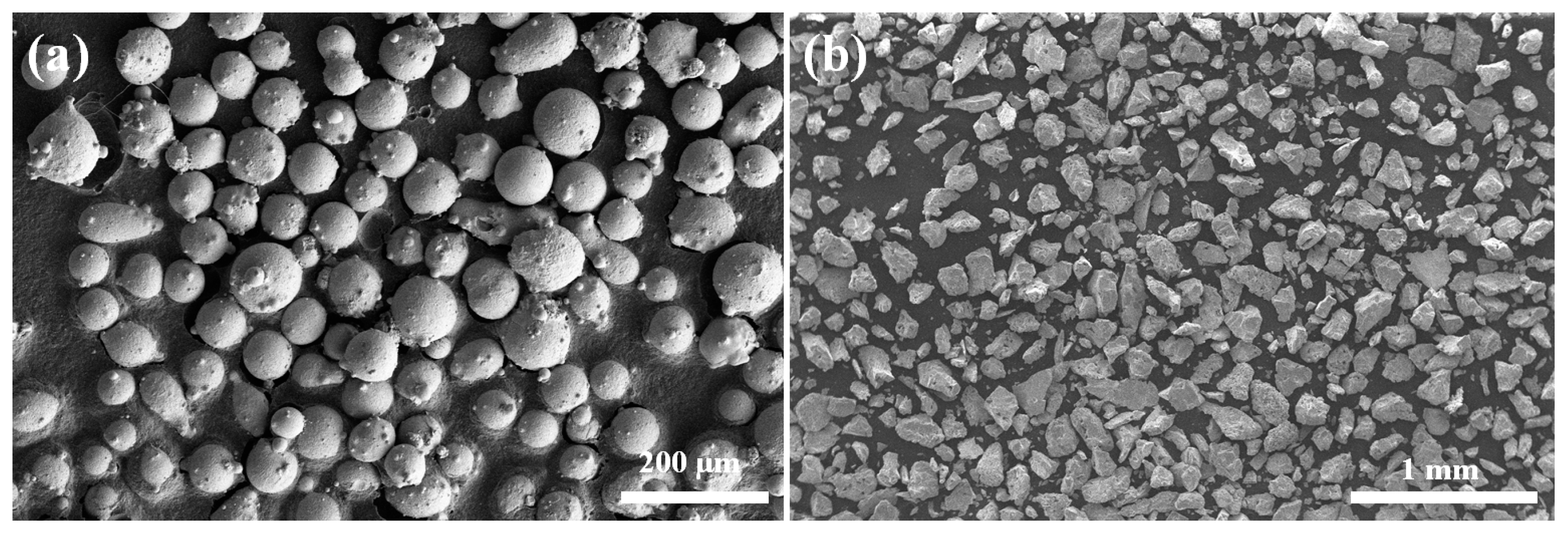
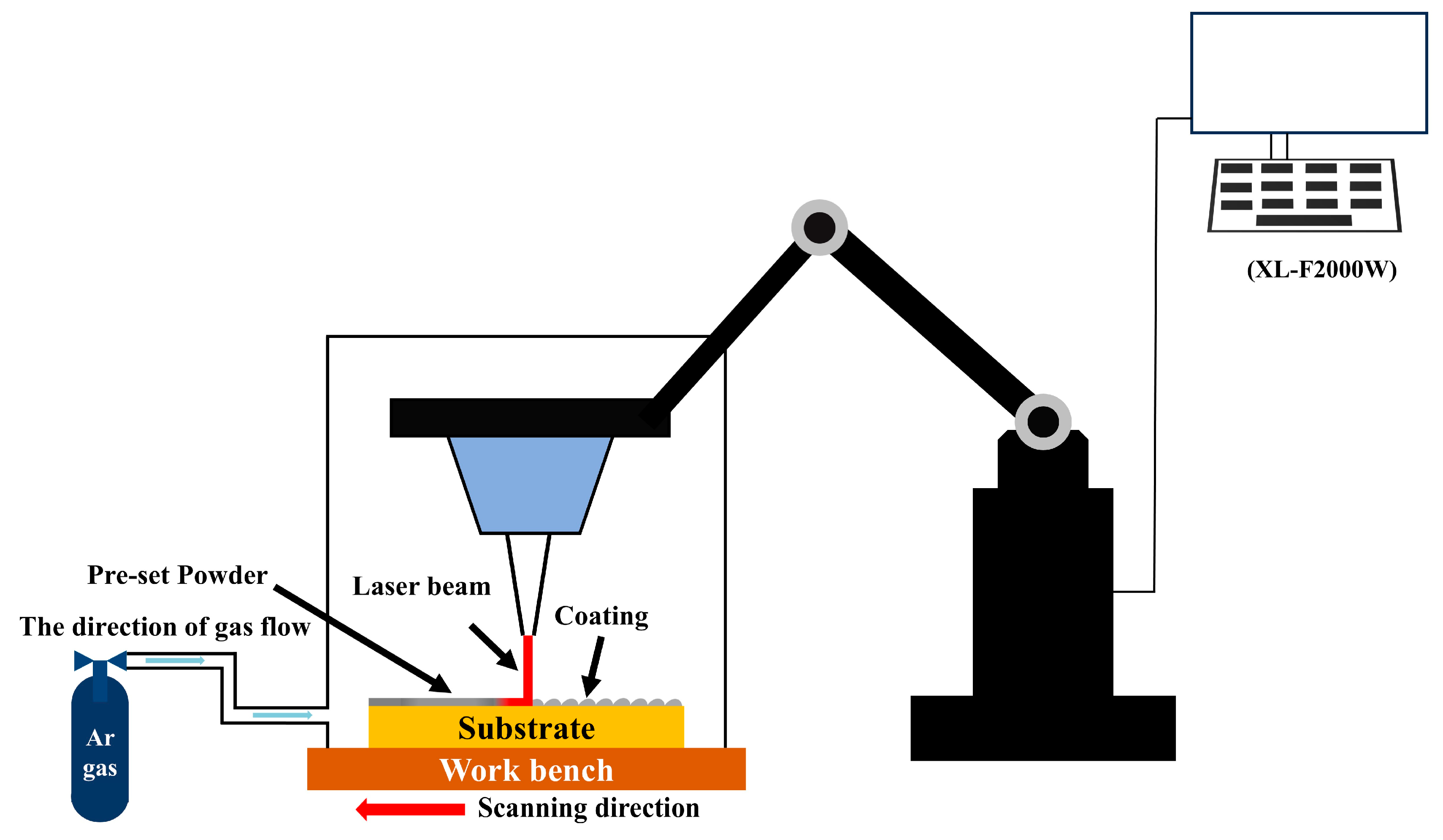
2. Experimental Procedures

In the experiment, Q235B with dimensions of 100 mm × 50 mm × 2 mm was selected as the substrate. Its surface was rust-removed with abrasive sandpaper and degreased with ethanol. Figure 1 is the SEM images of TiC (200 meshes) and CoCrFeNiMn (140–270 meshes) powders. Table 1 presents the chemical compositions of the CoCrFeNiMn HEA and Q235B.
An electronic balance was used to weigh the CoCrFeNiMn HEA and TiC powders with different contents. These powders were mechanically mixed in a ball mill at a rotational speed of 200 rpm for 3 h, and then dried in a desiccator for 24 h until dry. The pre-placed powder method was adopted. The preset powder is prepared with a 2 mm standard mold.
Processing was carried out using the XL-F2000W fiber continuous laser processing system, which is manufactured by Shenzhen Han’s Photonics Technology Co., Ltd., Shenzhen, China. The processing parameters were arranged as follows: laser power of 1200 W, defocusing amount of +5 mm, scanning speed of 700 mm/min, cladding length of 40 mm, 12 passes, 1.2 mm interval between each pass, and Ar shielding gas. The gas was first ventilated for 20 min and then kept flowing until the end of the experiment. The schematic diagram of the laser processing system is shown in Figure 2. Table 2 illustrates the naming method of samples.
The three samples were precisely trimmed to a cuboidal shape with dimensions of 10 mm × 10 mm × 2 mm. Subsequently, these trimmed samples were carefully embedded in a mold by means of a cold-mounting solution. A field-emission SEM (FEI, QUANT 250, Eindhoven) equipped with an energy-dispersive spectrometer (EDS, Noran System 7, Thermo Fisher Scientific, Waltham, MA, USA) was used to analyze the microstructure and elemental distribution. An X-ray diffractometer (Model: XRD-6100, Manufacturer: Shimadzu Corporation, Kyoto, Japan) was employed to measure the peak position and angle of the crystal. The diffraction angle ranged from 10° to 100° with a scanning speed of 4°/min. Based on experience and test results, we require an angle ranging from 10° to 90°.
A pin-disc-type friction wear tester, Model SFT—2M, manufactured by Lanzhou Zhongkehua Science and Technology Development Co., Ltd. in Lanzhou, China, and equipped with a displacement sensor, was utilized to determine the coefficient of friction (COF) and wear volume. The indenter is a Si3N4 steel ball with a diameter of 5 mm, the experimental load is 30 N, the rotational radius is 2 mm, the test duration is 60 min, and the rotational velocity is 200 rpm.
Electrochemical tests were conducted by the three-electrode method on the samples using an electrochemical workstation (CS350M, Corrtest, Wuhan, China) in a 3.5 wt% NaCl solution to analyze their corrosion resistance.
The open circuit potential (OCP) of the samples was measured for 3600 s. Subsequently, EIS was performed on the samples at a frequency range of 10−1–105 Hz. Finally, the potentiodynamic polarization curves were required in the scanning range of −0.5 V–1.5 V (vs. OCP), with a scanning rate set at 0.01 V/s.

3. Results and Analysis

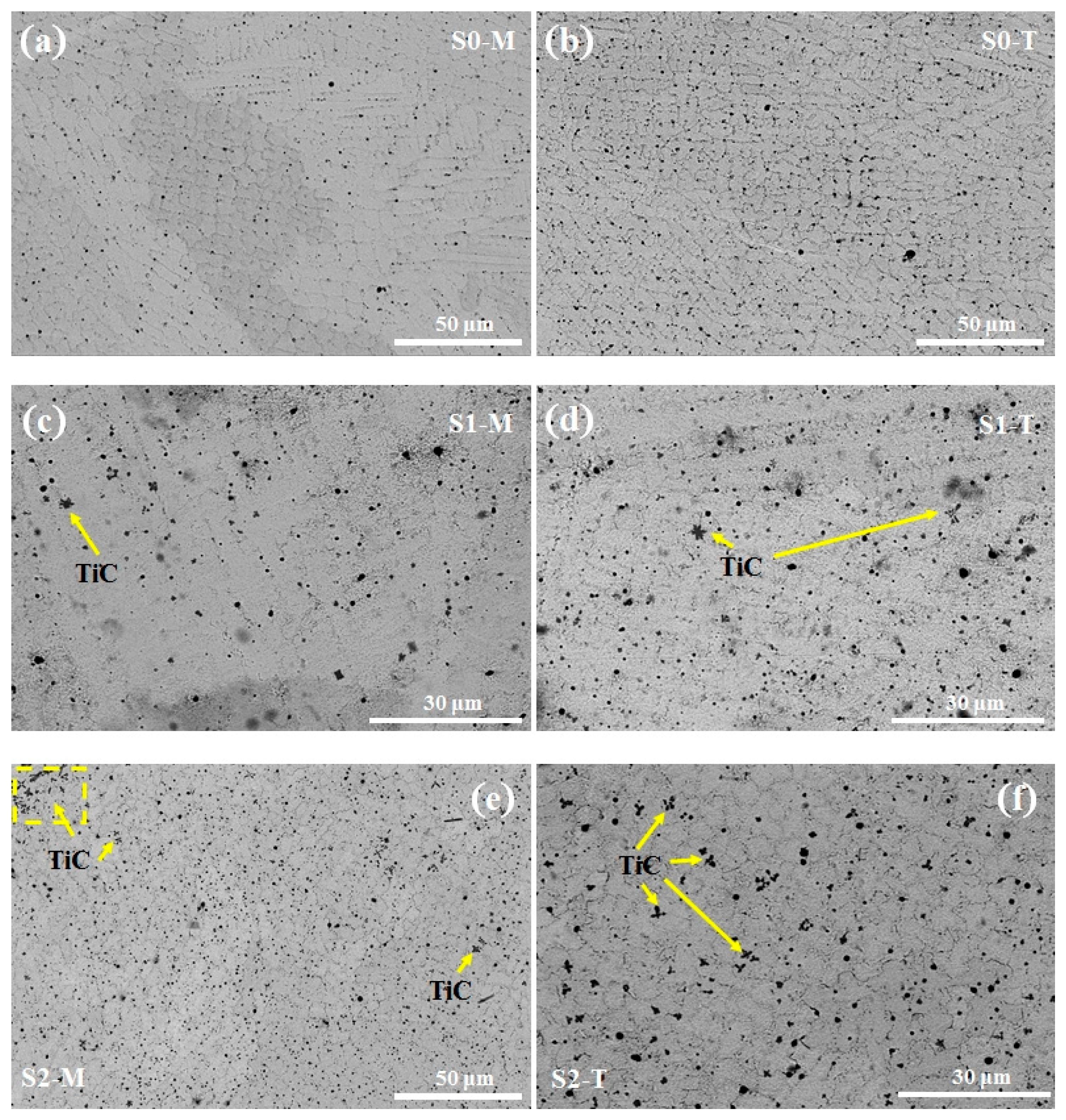
3.1. Metallographic Analysis

Figure 3a shows the phase constitutions of the S0, S1, and S2 coatings. One can see that the pure CoCrFeNiMn HEA without the addition of TiC is composed of a single FCC phase. As we know, the basic phase of CoCrFeNiMn HEA is FCC [21,22,23]. After adding TiC, the main peak of the coating is composed of the FCC phase, indicating that the addition of TiC does not cause a phase change in the main peak of the CoCrFeNiMn coating. First, one can observe the S1 sample. After adding 10% TiC, no new peaks appear in the coating. The main reason may be that the amount of additional TiC is too small [24]. The denser TiC moves to the bottom due to the influence of gravity, and thus there is less TiC at the top. In addition, the small amount of TiC may decompose due to the action of the laser, so there is less TiC in the coating, resulting in no obvious change in the XRD pattern. When the amount of additional TiC reaches 20%, the TiC and the M23C6 begin to appear. This indicates that part of the TiC remains unmelted in the coating. Part of the TiC melts and decomposes, and the decomposed C atoms form metal carbides. The M23C6 phase has a relatively high hardness. When it is dispersed in the alloy in the form of fine particles, it can play a role of dispersion strengthening, hindering the movement of dislocations, thus improving the hardness and strength of the alloy.
Based on Bragg’s law ( = 2dsinθ), when there is an increase in the lattice spacing, the main peak position shifts leftward [25,26]. During the LC cooling process, a large amount of residual tensile stress is likely to be generated, which will lead to an increase in the lattice spacing and cause the position of the main peak to shift to the left [27]. In addition, the atomic radius of TiC particles is relatively large, which can easily cause lattice distortion of the matrix [28]. Therefore, as the amount of additional TiC increases, the position of the main peak gradually shifts to the left. The microstress caused by lattice distortion does not have a certain direction and magnitude, which will lead to irregular changes in the interplanar spacing and ultimately cause the main peak to broaden [27]. From the comparison of the main peaks in Figure 3b–d, it is not difficult to find that the peak intensity of the XRD diffraction peak is weakened, and the width is increased, which is direct proof of the existence of microstress in the coating.

3.2. Microscopic Morphology

Figure 4 demonstrates the morphology of the samples, where all morphological transitions in different regions can be observed. The cooling rate of LC is very large. According to the constitutional supercooling criterion [29,30], the temperature gradient (G) and the solidification rate (R) have an important influence on the crystal growth of the coating. In the micro-molten pool, planar grains are formed, and simultaneously, cellular grains are formed in the middle part of the HEA coating. These laterally grown grains weaken the heat diffusion, thus reducing the G/R ratio. With the consumption of the heat, the surface layer of the molten pool begins to solidify, and the original grains become unstable and are turned into small columnar crystals, which is clearly shown in Figure 4a. Finally, the coating enters the solidification stage, and argon cooling on the surface is involved, which accelerates the solidification speed of the molten pool. The latent heat of crystallization of the liquid metal can be obtained from both the lower substrate and the upper cold argon, resulting in the smallest G/R ratio. The crystals are formed without directionality and become more fragmented, and the crystal size is smaller, which is clearly shown in Figure 4b. It is worth noting that there is only a small amount of TiC present in the middle and top regions of the coating with 10% TiC addition, as shown in Figure 4c,d. This also explains why no TiC phase was found in the XRD results. After the TiC addition amount reaches 20%, there are more slightly melted TiC particles in the top and middle regions of the coating, as seen in Figure 4e,f. The presence of more TiC hard phases in the top and middle regions of the S2 coating will improve the wear resistance of the coating.

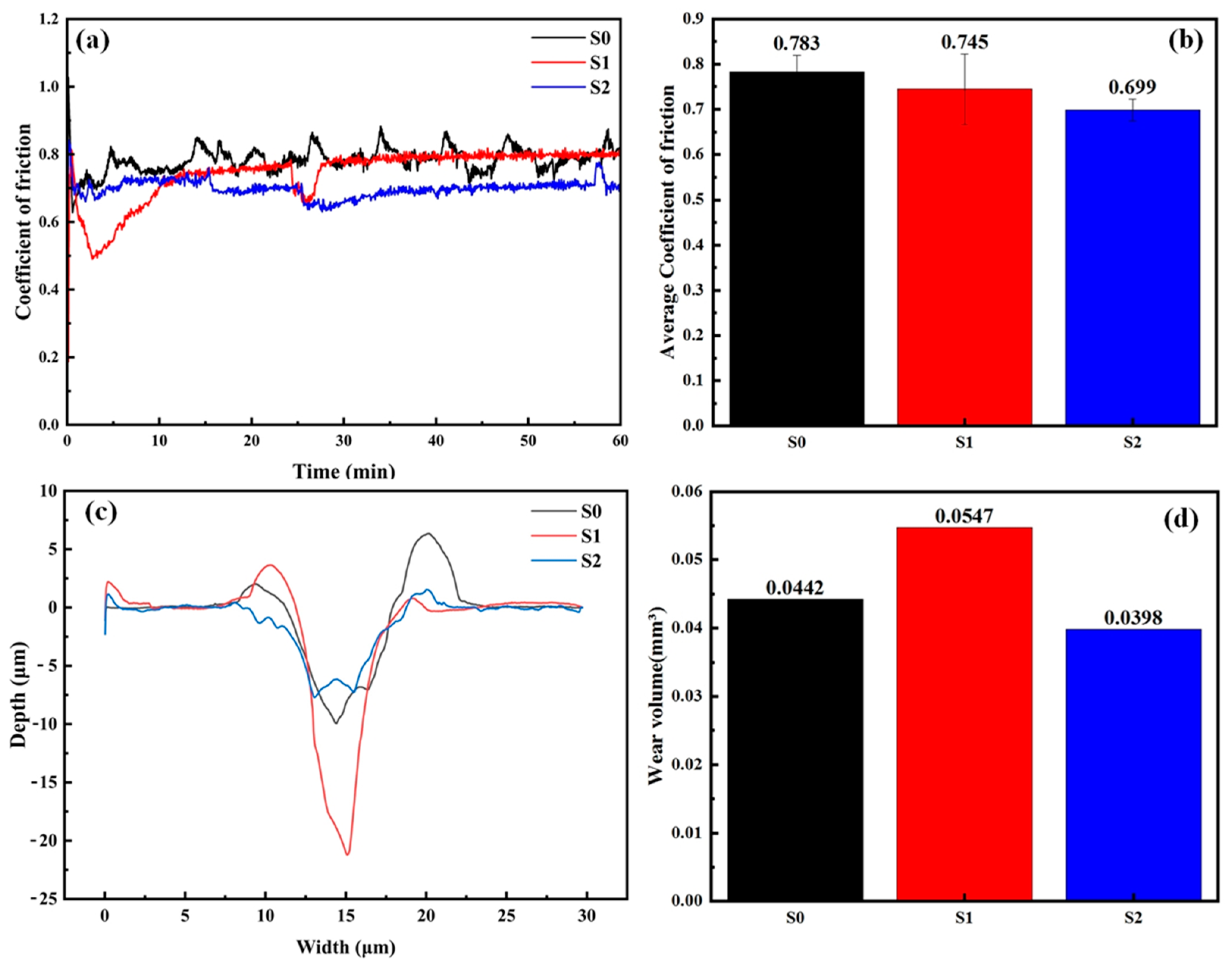
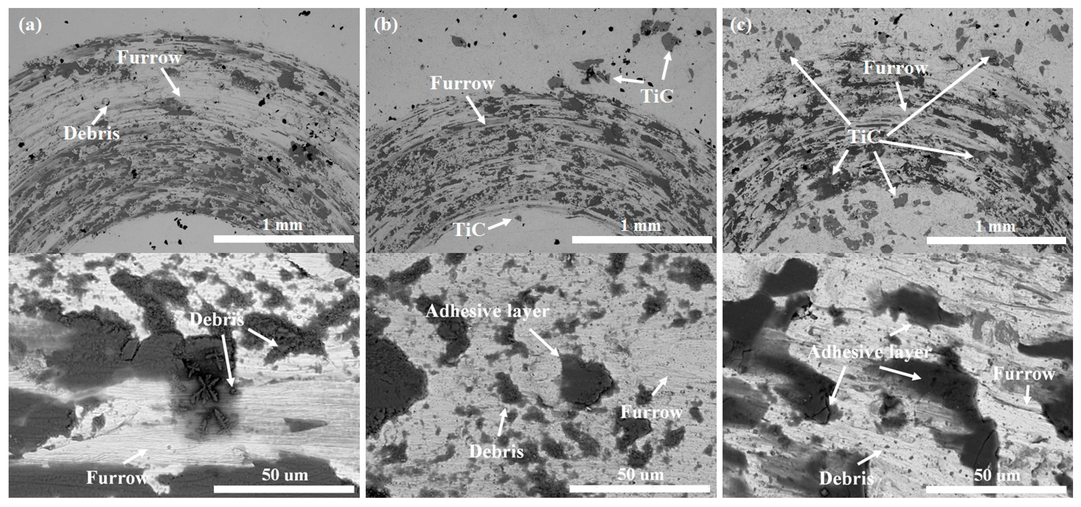
3.3. Wear Resistance

Figure 5a,b show the COF curves of the CoCrFeNiMn-(TiC)x HEA composite coatings when rubbed against Si3N4 steel balls. The COF first fluctuates significantly and then tends to be stable. It is generally believed that this effect is based on two factors: one is surface wearing, and the other is indenter sinking [31]. It can be seen that before the addition of TiC, the COF of the CoCrFeNiMn coating clearly fluctuates. After adding TiC, the COF of the coating begins to decrease and tends to be stable. When the amount of added TiC reaches 20%, the COF of the coating drops to its lowest at 0.699. By observing the wear profile of each coating in Figure 5c,d, it can be found that after adding TiC, the volume of the wear profile of the coating first increases and then decreases. Among them, the wear profile of sample S2 is the smallest, and the wear volume is 0.0398 mm3.
Combined with the COF coating results, it can be determined that sample S2 has the best wear resistance. The increase in the wear volume of sample S1 can be attributed to the fact that the small amount of hard phases leads to the lack of stress concentration in the coating during the wear process. During the wear process, a small amount of TiC hard phases accumulate in the middle and lower regions of the coating, causing the top of the coating to be worn away first. Subsequently, after the steel ball contacts the TiC hard phases in the middle and lower parts, it will wear away the hard phases from the surface of the coating and wear the coating together with the steel ball, resulting in an increase in the wear volume. The distribution of TiC in the middle and lower parts of the coating is also the main reason for the fluctuation of the COF of sample S1 at about 22 min. The main reason for the decrease in the wear volume of sample S2 is the increase in the TiC hard phases in the coating. There are more and more evenly distributed TiC hard phases in the middle part of the coating of sample S2 compared with sample S1. When the wear reaches the middle area of the coating, the stress imposed by the steel ball spreads uniformly among the TiC hard phases, reducing the wear loss of the coating. The decrease in the COF of sample S2 at 22 min indicates that the wear has reached the distribution area of TiC.
Figure 6 shows the SEM images of the wear tracks of the worn samples S0, S1, and S2. The low-magnification images on the top allow us to observe the complete wear profiles, while the images below are locally magnified high-magnification ones, enabling us to clearly see the details of the wear. These samples exhibit both abrasive wear and adhesive wear. As can be seen from Figure 6a, the wear of sample S0 is extremely severe, with deep furrows existing and some wear debris emerging simultaneously. In terms of the nature of the wear, this can be attributed to abrasive wear. The furrows of S1 and S2 are much shallower, and an adhesive layer appears at the same time, indicating that the addition of TiC can reduce abrasive wear while adhesive wear occurs. In addition, after adding TiC particles, the wear profiles of the coatings are significantly narrowed, as shown in Figure 6b,c. Among them, the wear profile of sample S2 is the narrowest and shallowest, and the delamination of the adhesive layer is quite obvious. This is consistent with the result shown in Figure 6c. It is worth noting that there is no TiC present in the wear profile of sample S1, which indicates that during the wear process, TiC is detached due to wear, aggravating the wear situation. However, TiC is distributed within the wear profile of sample S2, which reduces the stress concentration and enhances the wear properties of the coating. This is in line with the above analysis.

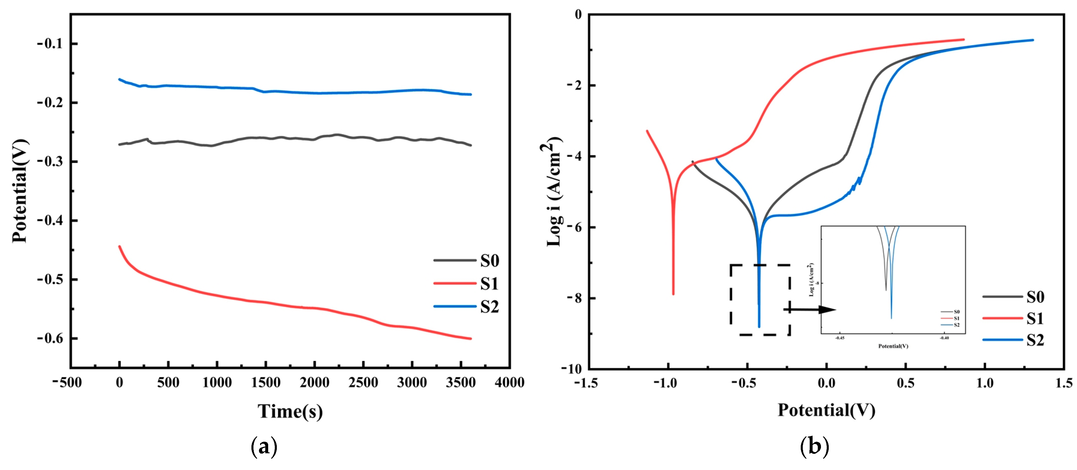
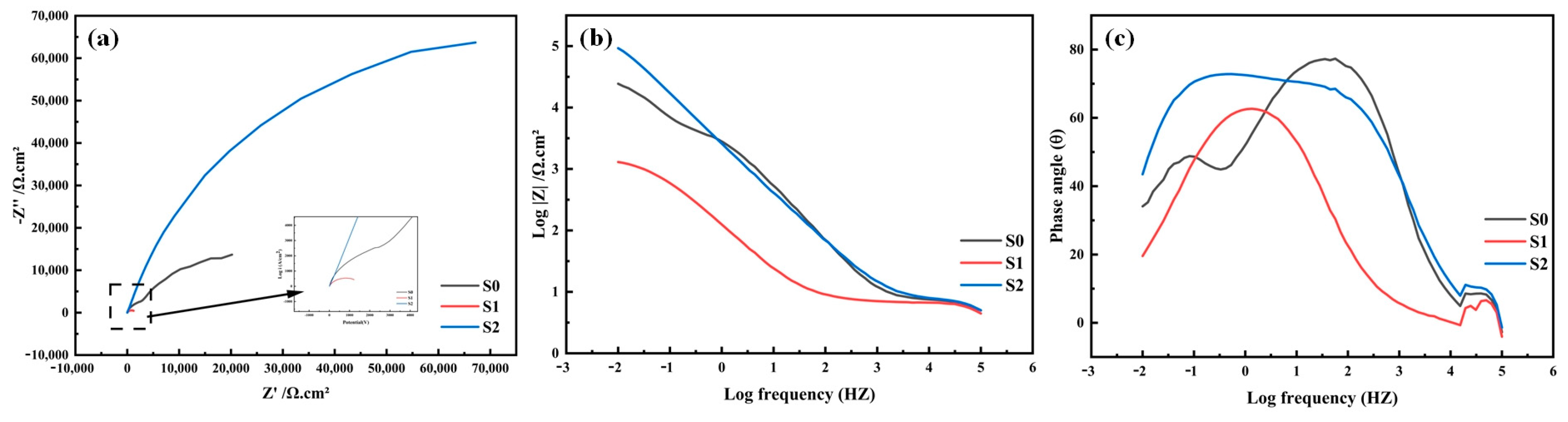
3.4. Corrosion Resistance

An OCP test for 3600 s was carried out on the samples that had been immersed in a 3.5% NaCl solution for 3 h to determine whether the samples formed a stable passivation film. Figure 7a presents the open-circuit potential curves of all the coatings. It can be observed that the open-circuit potential curves of the S0 and S2 coatings remained stable from the initial stage, which means that after 3 h of immersion treatment, one can successfully obtain stable passivation films. In contrast, the open-circuit potential curve of the S1 coating continued to decline. This indicates that samples S0 and S2 obtain more protective passivation films than sample S1. Among them, the test results of the open-circuit potential show that the S2 coating exhibits a higher open-circuit voltage, indicating its better steady-state response characteristics and stronger passivation tendency. It is capable of producing a passivation film that is more protective and stable, which effectively decreases the susceptibility to corrosion and decelerates the rate of the corrosion reaction [32,33]. In the 10 wt% TiC coating (S1), due to gravitational sedimentation and laser decomposition, the reinforcing phases, such as TiC, are unevenly distributed. This uneven distribution will lead to differences in composition and structure at different parts of the coating surface. As a result, in a corrosive environment, the reaction activities of various parts of the coating surface are different, making it easy to form local corrosion cells, accelerating the corrosion process, and further affecting the formation and stability of the passive film, thus resulting in poor passivation behavior.
Figure 7b shows the Tafel polarization curves of all the coatings. The anodic passivation region is a key indicator for evaluating the stability of the passivation film [34]. A wider and more stable passivation region means that there is a stable passivation film in the corrosion environment of the coating, indicating that these coatings have excellent corrosion resistance. In the anodic region, all three coatings enter the passivation region. This phenomenon indicates that it is possible for oxides and hydroxides to form on the surfaces of these three coatings, and then a passivation film is generated [33]. In the passivation region, with the increase in the voltage, the corrosion current of the S1 and S2 coatings remains almost unchanged, which indicates that the surfaces of these coatings are in a stable passivation state. In contrast, the corrosion current of the S0 coating keeps rising in the passivation region, which indicates that its passivation state is less stable compared with the other two coatings. In addition, the S2 coating has the lowest passivation current density and a larger passivation region, highlighting its strong surface passivation ability [35].
The self-corrosion potential (Ecorr) and self-corrosion current density (Icorr) obtained by the Tafel extrapolation method are significant parameters in assessing the corrosion resistance of the coating, with the outcomes depicted in Table 3. Ecorr is a concept within thermodynamics, signifying the probability of corrosion occurring, and the Icorr is a corrosion kinetic parameter, clearly reflecting the corrosion rate [36]. The S2 coating has the largest Ecorr and the smallest Icorr, followed by the S0 coating. The S1 coating has the smallest Ecorr and the largest Icorr. This indicates that, from the perspective of the thermodynamic and kinetic parameters of corrosion, the S2 coating has the best corrosion resistance, the S0 coating comes second, and the S1 coating has the worst corrosion resistance.
In order to more thoroughly explore the performance of the surface passivation films of the three coatings (S0, S1, and S2), as well as their kinetic characteristics during the corrosion process, EIS tests are carried out on all these samples. The Nyquist diagram is presented in Figure 8a. Scrutiny of this figure reveals that all the samples exhibit a nearly identical sunken capacitive semi-circular shape. This shape generally implies the existence of a charge transfer mechanism on the non-uniform surface, thus fully confirming the presence of the passivation film.
By analyzing the situation in the high-frequency region in depth, it can be found that the radii of the capacitive arcs have the following order: the radius of the capacitive arc of the S2 coating is larger than that of the S0 coating, and the S0 coating is larger than the S1 coating. The larger the radius of the capacitive loop, the higher the charge transfer resistance of the coating, the less likely the electron transfer is, the weaker the electrical conductivity is, the higher the impedance is, and correspondingly, the stronger the corrosion resistance is. Therefore, it can be concluded that among these three samples, the S2 coating has the best corrosion resistance, while the S1 coating has the worst corrosion resistance.
Figure 8b,c show the Bode diagrams of the three coatings. In the low-frequency region, the value of the impedance modulus can reflect the situation of the charge transfer resistance. Consequently, the overall corrosion resistance of the coating is able to be evaluated in an intuitive manner through the parameter of |Z|0.01Hz. Through analysis, it can be known that the order of the values of |Z|0.01Hz is S2 coating > S0 coating > S1 coating, and this order is consistent with the change trend of the radius of the capacitive arc in the Nyquist plot. Meanwhile, in the low-frequency region, the phase angle of S2 is also the largest. The increase in both the |Z|0.01Hz value and the phase angle further confirms that a thicker and denser passivation film has been formed in the S2 coating. Therefore, the protective performance of this coating has been significantly improved.
Above all, adding a small amount of TiC is not conducive to the improvement of the corrosion resistance of the CoCrFeNiMn coating. However, when the amount of TiC added reaches 20%, the corrosion resistance of the CoCrFeNiMn coating can be greatly improved.

4. Conclusions

In this work, CoCrFeNiMn high-entropy alloy-based composite coatings with diverse TiC contents (0, 10, 20 wt%) were successfully prepared using LC technology, and the synergistic regulation mechanism of TiC addition on the wear properties and corrosion resistance of the coatings was revealed. Experiments show that the 20 wt% TiC composite coating (S2) exhibits comprehensive performance advantages due to the uniformly distributed TiC hard phases, optimized stress dispersion ability, and stable passivation behavior. The cardinal research inferences are presented as follows:
(1)
In the coating (S2) with 20 wt% TiC addition, the TiC and M23C6 phases are uniformly distributed in the high-entropy alloy matrix, and lattice distortion occurs in the coating (broadening and leftward shift of the XRD peaks). In contrast, in the 10 wt% TiC coating (S1), due to gravitational sedimentation and laser decomposition, the reinforcing phase is locally enriched and unevenly distributed.
(2)
The S2 coating has the lowest coefficient of friction and wear volume because the uniformly distributed hard phases can disperse the stress. However, in the S1 coating, due to the detachment of TiC and stress concentration, the wear is aggravated.
(3)
In a 3.5% NaCl solution, compared with samples S0 and S1, sample S2 showed the most outstanding corrosion resistance because of the protective effect of the dense passivation film.

Author Contributions

Conceptualization, Q.Z. and C.L.; Methodology, F.L.; Software, J.H.; Investigation, Q.Z.; Resources, J.H., Z.W., B.M. and C.L.; Writing—original draft, Q.Z.; Writing—review & editing, F.L., Z.W., B.M. and C.L.; Supervision, Z.W., B.M. and C.L.; Funding acquisition, C.L. All authors have read and agreed to the published version of the manuscript.

Funding

This research was funded by the National Natural Science Foundation of China (12074398).

Data Availability Statement

The original contributions presented in this study are included in the article. Further inquiries can be directed to the corresponding author. The raw data supporting the conclusions of this article will be made available by the authors on request.

Conflicts of Interest

The authors declare no conflict of interest.

References

  1. Li, P.; Zhang, J.; Yang, T.; Zhang, T.; Zhang, J.; Lin, J.; Yan, Y.; Li, C.; Si, X.; Cao, J.; et al. Characteristics, applications and perspective of high entropy alloys for interfacial joining: A review. J. Manuf. Process. 2024, 110, 303–317. [Google Scholar] [CrossRef]
  2. Li, D.; Liaw, P.K.; Xie, L.; Zhang, Y.; Wang, W. Advanced high-entropy alloys breaking the property limits of current materials. J. Mater. Sci. Technol. 2024, 186, 219–230. [Google Scholar] [CrossRef]
  3. Abdullah, M.R.; Peng, Z. Review and perspective on additive manufacturing of refractory high entropy alloys. Mater. Today Adv. 2024, 22, 100497. [Google Scholar] [CrossRef]
  4. Liang, G.; Jin, G.; Cui, X.; Qiu, Z.; Wang, J. Synthesis and characterization of directional array TiN-reinforced AlCoCrCuNiTi high-entropy alloy coating by magnetic-field-assisted LC. J. Mater. Eng. Perform. 2021, 30, 3568–3576. [Google Scholar] [CrossRef]
  5. Sun, D.; Zhu, L.S.; Cai, Y.C.; Yan, Y.N.; Ge, F.Y.; Shan, M.D.; Tian, Y.B.; Han, J.; Jiang, Z.Y. Tribology comparison of laser-cladded CrMnFeCoNi coatings reinforced by three types of ceramic (TiC/NbC/B4C). Surf. Coat. Technol. 2022, 450, 129013. [Google Scholar] [CrossRef]
  6. Sun, D.; Cai, Y.C.; Zhu, L.S.; Gao, F.F.; Shan, M.D.; Manladan, S.M.; Geng, K.P.; Han, J.; Jiang, Z.Y. High-temperature oxidation and wear properties of TiC-reinforced CrMnFeCoNi high entropy alloy composite coatings produced by LC. Surf. Coat. Technol. 2022, 438, 128407. [Google Scholar] [CrossRef]
  7. Wei, Y.N.; Chen, Y.; Guo, B.B.; Zhu, L.H. The microstructure and mechanical properties of TiC-reinforced W-matrix composites prepared by spark plasma sintering. Int. J. Refract. Met. Hard Mater. 2023, 112, 106158. [Google Scholar] [CrossRef]
  8. Zhuang, D.D.; Tao, W.W.; Du, B.; Zhang, S.H.; Lian, X.L.; Wang, F. Microstructure and properties of TiC-enhanced CrMnFeCoNi high-entropy alloy coatings prepared by LC. Tribol. Int. 2023, 180, 108246. [Google Scholar] [CrossRef]
  9. Xiong, J.K.; Sun, D.; Dong, N.; Cai, Y.C.; Wang, D.Y.; Luo, Z. Oxidation mechanism of TiC reinforced CrMnFeCoNi composite coatings by LC at 600 °C/900 °C. Mater. Lett. 2022, 324, 132710. [Google Scholar] [CrossRef]
  10. Zhou, J.L.; Cheng, Y.H.; He, B.; Wan, Y.X.; Chen, H.; Wang, Y.F.; Yang, J.Y. Enhancement of high-entropy alloy coatings with multi-scale TiC ceramic particles via high-speed LC: Microstructure, wear and corrosion. Appl. Surf. Sci. 2025, 685, 162061. [Google Scholar] [CrossRef]
  11. Zhao, W.; Kedong, Y.; Ma, Q.I.; Song, C.; Xiao, G.; Zhang, H.; Lv, Y.; Guo, N.; Li, Z. Synergistic effects of Mo and in-situ TiC on the microstructure and wear resistance of AlCoCrFeNi high entropy alloy fabricated by LC. Tribol. Int. 2023, 188, 108827. [Google Scholar] [CrossRef]
  12. Zhang, X.R.; Cui, X.F.; Qi, M.; Zhang, Q.; Qi, Y.P.; Jin, G. Corrosion and passivation behavior of in-situ TiC reinforced Al 0.1 CrNbSi 0.1 TaTiV refractory high entropy alloy coatings via doping C. Corros. Sci. 2024, 227, 111736. [Google Scholar] [CrossRef]
  13. Shang, X.; Liu, Q.; Guo, Y.; Ding, K.; Liao, T.; Wang, F. Nano-TiC reinforced [Cr–Fe 4 4 4 ]Cr 3 high-entropy-alloy composite coating fabricated by LC. J. Mater. Res. Technol. 2022, 21, 2076–2088. [Google Scholar] [CrossRef]
  14. Wu, H.; Wang, L.; Zhang, S.; Wu, C.L.; Zhang, C.H.; Sun, X.Y. Corrosion and cavitation erosion behaviors of laser clad FeNiCoCr high-entropy alloy coatings with different types of TiC reinforcement. Surf. Coat. Technol. 2023, 471, 129910. [Google Scholar] [CrossRef]
  15. Zhang, J.; Jia, T.; Zhu, H.G.; Xie, Z.H. Microstructure and mechanical properties of in-situ TiC reinforced FeCoNiCu2.0 high entropy alloy matrix composites. Mater. Sci. Eng. A 2021, 822, 141671. [Google Scholar] [CrossRef]
  16. Wilson, J.M.; Shin, Y.C. Microstructure and wear properties of laser-deposited functionally graded Inconel 690 reinforced with TiC. Surf. Coat. Technol. 2012, 207, 517–522. [Google Scholar] [CrossRef]
  17. Yu, K.D.; Zhao, W.; Li, Z.; Guo, N.; Xiao, G.C.; Zhang, H. High–temperature oxidation behavior and corrosion resistance of in–situ TiC and Mo reinforced AlCoCrFeNi–based high entropy alloy coatings by LC. Ceram Int. 2023, 49, 10151–10164. [Google Scholar] [CrossRef]
  18. Wu, C.L.; Xu, T.Z.; Wang, Z.Y.; Zhang, C.H.; Zhang, S.; Ni, C.L. Laser surface alloying of FeCoCrAlNiTi high entropy alloy composite coatings reinforced with TiC on 304 stainless steel to enhance wear behavior. Ceram Int. 2022, 48, 20690–20698. [Google Scholar] [CrossRef]
  19. Liu, H.; Liu, J.; Chen, P.J.; Yang, H.F. Microstructure and high temperature wear behaviour of in–situ TiC reinforced AlCoCrFeNi–based high–entropy alloy composite coatings fabricated by LC. Opt. Laser Technol. 2019, 118, 140–150. [Google Scholar] [CrossRef]
  20. Jiang, D.; Hong, C.; Zhong, M.; Alkhayat, M.; Weisheit, A.; Gasser, A.; Zhang, H.; Kelbassa, I.; Poprawe, R. Fabrication of nano-TiCp reinforced Inconel 625 composite coatings by partial dissolution of micro-TiCp through LC energy input control. Surf. Coat. Technol. 2014, 249, 125–131. [Google Scholar] [CrossRef]
  21. Luo, F.Y.; Wang, S.S.; Shi, W.Q.; Xiong, Z.Y.; Huang, J. Wear behavior of single-layer graphene oxide reinforced CoCrFeNiMn HEA coating by LC. Intermetallics 2024, 175, 108512. [Google Scholar] [CrossRef]
  22. Yeh, J.; Chen, S.; Lin, S.; Gan, J.; Chin, T.; Shun, T.; Tsau, C.; Chang, S. Nanostructured high-entropy alloys with multiple principal elements: Novel alloy design concepts and outcomes. Adv. Eng. Mater. 2004, 6, 299–303. [Google Scholar] [CrossRef]
  23. Cantor, B.; Chang, I.T.H.; Knight, P.; Vincent, A.J.B. Microstructural development in equiatomic multicomponent alloys. Mater. Sci. Eng. A 2003, 3571, 257–264. [Google Scholar] [CrossRef]
  24. Wang, T.; Zhu, L.; Song, H.Y.; Wang, H. Effect of WC-17Co content on microstructure and properties of IN718 composites prepared by laser cladding. Opt. Laser Technol. 2022, 148, 107780. [Google Scholar] [CrossRef]
  25. Luo, F.Y.; Shi, W.Q.; Xiong, Z.Y.; Huang, J. Microstructure and properties analysis of AlCoCrFeNi high-entropy alloy/iron-based amorphous composite coatings prepared by LC. J. Non-Cryst. Solids 2024, 624, 122732. [Google Scholar] [CrossRef]
  26. Luo, F.Y.; Wang, S.S.; Shi, W.Q.; Zhao, Y.; Huang, J. Wear behavior and corrosion resistance of laser-clad Ni60-1% carbon nanotubes coating. Surf. Coat. Technol. 2024, 482, 130686. [Google Scholar] [CrossRef]
  27. Gu, Z.; Xi, S.Q.; Sun, C.F. Microstructure and properties of laser cladding and CoCr2.5FeNi2Tix high-entropy alloy composite coatings. J. Alloys Compd. 2020, 819, 152986. [Google Scholar] [CrossRef]
  28. Li, Y.T.; Fu, H.G.; Ma, T.J.; Wang, K.M.; Yang, X.J.; Lin, J. Microstructure and wear resistance of AlCoCrFeNi-WC/TiC composite coating by laser cladding. Mater. Charact. 2022, 194, 112479. [Google Scholar] [CrossRef]
  29. Ismail, H.; Vaclav, O.; Kornel, C.; Jeffthm, D. Microstructure and Phase Formation in a Rapidly Solidified Laser-Deposited Ni-Cr-B-Si-C Hardfacing Alloy. Metall. Mater. Trans. A 2014, 45A2, 878–892. [Google Scholar]
  30. Liu, X.M. Mechanism and control of the nick-based alloy WC laser cladded layer microstructure. Appl. Laser 2006, 5, 299–302. [Google Scholar]
  31. Li, Y.H.L.J.; Tao, Y.F.; Hu, L.F. High-temperature wear and oxidation behaviors of TiNi/Ti2Ni matrix composite coatings with TaC addition prepared on Ti6Al4V by laser cladding. Appl. Surf. Sci. 2017, 402, 478–494. [Google Scholar]
  32. Yuan, W.Y.; Li, R.F.; Zhu, Y.Y.; Zhao, Y.; Zhang, X.Q.; Liu, B.; Zhang, B.S. Structure and properties of nickel-plated CNTs/Fe-based amorphous composite coatings fabricated by high-speed LC. Surf. Coat. Technol. 2022, 438, 128363. [Google Scholar] [CrossRef]
  33. Shahriari, A.; Ghaffari, M.; Khaksar, L.; Nasiri, A.; Hadadzadeh, A.; Amirkhiz, B.S.; Mohammadi, M. Corrosion resistance of 13wt% Cr martensitic stainless steels: Additively manufactured CX versus wrought ni-containing AISI 420. Corros. Sci. 2021, 184, 109362. [Google Scholar] [CrossRef]
  34. Muangtong, P.; Rodchanarowan, A.; Chaysuwan, D.; Chanlek, N.; Goodall, R. The corrosion behaviour of CoCrFeNix x = Cu, Al, Sn) high entropy alloy systems in chloride solution. Corros. Sci. 2020, 172, 108740. [Google Scholar] [CrossRef]
  35. Zhou, Y.Q.; Kong, D.C.; Wang, L.; Li, R.X.; Ni, X.Q.; Cheng, M.; Dong, C.F.; Engelberg, D. Pit growth kinetics of additively manufactured MoNi over-alloyed type 316L stainless steel. J. Mater. Res. Technol. 2023, 27, 7532–7547. [Google Scholar] [CrossRef]
  36. Li, J.X.; Liu, Z.D.; Ma, H.R.; Liu, Q.B.; Mao, J.; Zhang, J.; Kong, Y. Comparative study on the corrosion behaviour of 1.4529 super austenitic stainless steel and laser-cladding 1.4529 coating in simulated desulfurized flue gas condensates. Corros. Sci. 2022, 209, 110794. [Google Scholar] [CrossRef]
Figure 1. SEM morphologies of different powders. (a) CoCrFeNiMn; (b) TiC.
Lubricants 13 00210 g001
Figure 2. Schematic of the laser cladding process system.
Lubricants 13 00210 g002
Figure 3. (a) XRD pattern of the sample; (bd) enlarged spectrum of the position of the main peak in XRD.
Lubricants 13 00210 g003
Figure 4. Cross-sectional SEM images of different samples. (a,b) S0 sample; (c,d) S1 sample; (e,f) S2 sample.
Lubricants 13 00210 g004
Figure 5. (a) COF; (b) average COF; (c) two-dimensional wear patterns; (d) wear volume.
Lubricants 13 00210 g005
Figure 6. The wear morphologies of the samples at high and low magnifications. (a) S0 sample; (b) S1 sample; (c) S2 sample.
Lubricants 13 00210 g006
Figure 7. (a) Open circuit potential curves of HEA coatings; (b) Tafel polarization plots of HEA coatings.
Lubricants 13 00210 g007
Figure 8. EIS spectra for samples. (a) Nyquist diagram; (b,c) Bode diagram.
Lubricants 13 00210 g008
Table 1. Chemical composition of primitive materials.
MaterialChemical Composition (Mass. %)
CSiMnFeCrNiCo
Q235B0.170.160.38Bal.---
CoCrFeNiMn0.025-19.3619.7618.7120.8121.24
Table 2. Names of coatings with various powder mass fractions.
Name of CoatingsMass Fractions/(Mass.%)
S0CoCrFeNiMn
S1CoCrFeNiMn + 10 wt% TiC
S2CoCrFeNiMn + 20 wt% TiC
Table 3. Electrochemical parameters derived from Tafel curves.
ParameterEcorr
(V)
Icorr
(A/cm2)
Sample
S0−0.428 2.669   × 10 6
S1−0.968 2.920   × 10 5
S2−0.425 1.119   × 10 7
Disclaimer/Publisher’s Note: The statements, opinions and data contained in all publications are solely those of the individual author(s) and contributor(s) and not of MDPI and/or the editor(s). MDPI and/or the editor(s) disclaim responsibility for any injury to people or property resulting from any ideas, methods, instructions or products referred to in the content.

