Corrosion Resistance of SAE 5160 Steel Deposited by Duplex Simultaneous Treatment with Hastelloy Cathodic Cage

 , , , ,
Abstract
1. Introduction
2. Materials and Methods
3. Results and Discussion
4. Conclusions
Author Contributions
Funding
Data Availability Statement
Conflicts of Interest
References
- Han, X.; Zhang, Z.; Hou, J.; Barber, G.C.; Qiu, F. Tribological Behavior of Shot Peened/Austempered AISI 5160 Steel. Tribol. Int. 2020, 145, 106197. [Google Scholar] [CrossRef]
- Perla, S.; Kulkarni, S.; Balachandran, G.; Balasubramanian, V. Influence of Section Size and Grain Size on the Microstructure Evolution and Mechanical Properties in Steel Grade AISI 5160. Trans. Indian Inst. Met. 2017, 70, 2449–2458. [Google Scholar] [CrossRef]
- Ruden, A.; Restrepo-Parra, E.; Paladines, A.U.; Sequeda, F. Corrosion Resistance of CrN Thin Films Produced by Dc Magnetron Sputtering. Appl. Surf. Sci. 2013, 270, 150–156. [Google Scholar] [CrossRef]
- Escobar, C.; Caicedo, J.C.; Aperador, W.; Delgado, A.; Prieto, P. Improve on Corrosion Resistant Surface for AISI 4140 Steel Coated with VN and HfN Single Layer Films. Int. J. Electrochem. Sci. 2013, 8, 7591–7607. [Google Scholar] [CrossRef]
- Asadian, K.; Samiee, M.; Mafi, M. Wear Mechanism and Electrochemical Properties of Different Interlayers on DLC Film Deposited by PECVD Technique. J. Bio. Tribo. Corros. 2024, 10, 30. [Google Scholar] [CrossRef]
- Pillis, M.F.; Geribola, G.A.; Scheidt, G.; De Araújo, E.G.; De Oliveira, M.C.L.; Antunes, R.A. Corrosion of Thin, Magnetron Sputtered Nb2O5 Films. Corros. Sci. 2016, 102, 317–325. [Google Scholar] [CrossRef]
- Kusmanov, S.A.; Smirnov, A.A.; Silkin, S.A.; Belkin, P.N. Increasing Wear and Corrosion Resistance of Low-Alloy Steel by Anode Plasma Electrolytic Nitriding. Surf. Coat. Technol. 2016, 307, 1350–1356. [Google Scholar] [CrossRef]
- Satbayeva, Z.; Maulit, A.; Ispulov, N.; Baizhan, D.; Rakhadilov, B.; Kusainov, R. Electrolytic Plasma Nitriding of Medium-Carbon Steel 45 for Performance Enhancement. Crystals 2024, 14, 895. [Google Scholar] [CrossRef]
- Belkin, P.N.; Yerokhin, A.; Kusmanov, S.A. Plasma Electrolytic Saturation of Steels with Nitrogen and Carbon. Surf. Coat. Technol. 2016, 307, 1194–1218. [Google Scholar] [CrossRef]
- Grigoriev, S.N.; Tambovskiy, I.; Mukhacheva, T.; Kusmanova, I.; Podrabinnik, P.; Khmelevsky, N.; Suminov, I.V.; Kusmanov, S. Influence of Electrophysical Parameters of Plasma Electrolytic Treatment on the Structure, Morphology and Tribological Properties of 90crsi Tool Steel Surface 2024. [CrossRef]
- Kusmanov, S.A.; Tambovskiy, I.V.; Korableva, S.S.; Dyakov, I.G.; Burov, S.V.; Belkin, P.N. Enhancement of Wear and Corrosion Resistance in Medium Carbon Steel by Plasma Electrolytic Nitriding and Polishing. J. Mater. Eng. Perform. 2019, 28, 5425–5432. [Google Scholar] [CrossRef]
- Kusmanov, S.A.; Smirnov, A.A.; Silkin, S.A.; Belkin, P.N. Modification of Low-Alloy Steel Surface by Plasma Electrolytic Nitriding. J. Mater. Eng. Perform. 2016, 25, 2576–2582. [Google Scholar] [CrossRef]
- Pereira, J.C.; Dos Santos, L.P.M.; Alcanfor, A.A.C.; De Sant’Ana, H.B.; Feitosa, F.X.; Campos, O.S.; Correia, A.N.; Casciano, P.N.S.; De Lima-Neto, P. Effects of Electrodeposition Parameters on Corrosion Resistance of ZnSn Coatings on Carbon Steel Obtained from Eutectic Mixture Based on Choline Chloride and Ethylene Glycol. J. Alloys Compd. 2021, 886, 161159. [Google Scholar] [CrossRef]
- Silva Filho, W.L.C.D.; Salgueiro, G.T.F.; Malta, M.I.C.; Silva, J.J.D.; Silva, R.G.C.D.; Urtiga Filho, S.L.; Vieira, M.R.S. Obtaining and Characterization of Super-Hydrophobic Nickel Coatings Applied on ASTM A36 Carbon Steel via Electrodeposition as an Alternative for Anticorrosive Protection. Mater. Res. 2024, 27, e20240061. [Google Scholar] [CrossRef]
- Yoo, B.Y.; Hernandez, S.C.; Park, D.-Y.; Myung, N.V. Electrodeposition of FeCoNi Thin Films for Magnetic-MEMS Devices. Electrochim. Acta 2006, 51, 6346–6352. [Google Scholar] [CrossRef]
- Demir, K.Ç. The Investigation of the Corrosion Behavior of CZTS Thin Films Prepared via Electrodeposition. Sci. Semicond. Process. 2021, 123, 105553. [Google Scholar] [CrossRef]
- Popescu, A.-M.J.; Branzoi, F.; Constantin, I.; Anastasescu, M.; Burada, M.; Mitrică, D.; Anasiei, I.; Olaru, M.-T.; Constantin, V. Electrodeposition, Characterization, and Corrosion Behavior of CoCrFeMnNi High-Entropy Alloy Thin Films. Coatings 2021, 11, 1367. [Google Scholar] [CrossRef]
- Sheffer, M.; Groysman, A.; Mandler, D. Electrodeposition of Sol–Gel Films on Al for Corrosion Protection. Corros. Sci. 2003, 45, 2893–2904. [Google Scholar] [CrossRef]
- Basu, A.; Majumdar, J.D.; Alphonsa, J.; Mukherjee, S.; Manna, I. Corrosion Resistance Improvement of High Carbon Low Alloy Steel by Plasma Nitriding. Mater. Lett. 2008, 62, 3117–3120. [Google Scholar] [CrossRef]
- Fonseca Oliveira, L.; Velho De Castro, V.; Zen Vasconcellos, M.A.; Klein Das Neves, J.C.; De Fraga Malfatti, C.; Da Silva Rocha, A. Effects of Gas Mixture on Active Screen Plasma Nitriding and Post-Oxidation of a 4140 Steel. Surf. Coat. Technol. 2024, 476, 130272. [Google Scholar] [CrossRef]
- Zhang, N.; Yang, Z.; Li, H.; Chen, B.; Song, S.; Qian, C.; Liu, C.; Yang, B. Effect of N2/Ar Ratio on Microstructure and Tribological Property of Arc Plasma-Assisted Nitrided 40CrNiMoA Steel. Trans. Indian Inst. Met. 2023, 76, 2735–2743. [Google Scholar] [CrossRef]
- Souza Dos Reis Junior, J.; Cristino De Sousa Brito, M.; Abreu De Oliveira, P.; Santana Libório, M.; Matos Monção, R.; Sousa Nunes, M.; Augusto Antônio Júnior, C.; Sgarbi Rossino, L.; Henrique De Carvalho Costa, T.; Ciqueira Feitor, M.; et al. Influence of Quenching and Tempering on the Tribological and Corrosion Behavior of Plasma-Nitrided Society of Automotive Engineers 52100. Steel Res. Int. 2024, 95, 2300512. [Google Scholar] [CrossRef]
- Costa, P.M.O.; Serra, P.L.C.; Monção, R.M.; Menezes, A.S.D.; Borges, F.M.R.; Costa, T.H.D.C.; Sousa, R.R.M.D. Influence of Hastelloy’s Cathodic Cage Plasma Deposition on Corrosion Resistance of AISI 304 Stainless Steel and of AISI D6 Tool Steel. Mat. Res. 2021, 24, e20200267. [Google Scholar] [CrossRef]
- Araújo, A.G.F.; Naeem, M.; Araújo, L.N.M.; Libório, M.S.; Danelon, M.R.; Monção, R.M.; Rossino, L.S.; Feitor, M.C.; Do Nascimento, R.M.; Costa, T.H.C.; et al. Duplex Treatment with Hastelloy Cage on AISI 5160 Steel Cutting Tools. Mater. Sci. Technol. 2022, 38, 499–506. [Google Scholar] [CrossRef]
- Nishimoto, A.; Nii, H.; Narita, R.; Akamatsu, K. Simultaneous Duplex Process of TiN Coating and Nitriding by Active Screen Plasma Nitriding. Surf. Coat. Technol. 2013, 228, S558–S562. [Google Scholar] [CrossRef]
- Kovács, D.; Dobránszky, J.; Fodor, T.; Takáts, V.; Bonyár, A. Investigation of the ASPN Process of Low Alloy Steel by Using Ni or Cr Coated Active Screens. Surf. Coat. Technol. 2020, 394, 125638. [Google Scholar] [CrossRef]
- Hamashima, S.; Nishimoto, A. Effects of Nickel Screen on Active Screen Plasma Nitriding. Mater. Trans. 2022, 63, 939–947. [Google Scholar] [CrossRef]
- Fernades, F.; Filho, E.R.; Souza, I.; Nascimento, I.; Sousa, R.; Almeida, E.; Feitor, M.; Costa, T.; Naeem, M.; Iqbal, J. Novel Synthesis of Copper Oxide on Fabric Samples by Cathodic Cage Plasma Deposition. Polym. Adv. Technol. 2020, 31, 520–526. [Google Scholar] [CrossRef]
- Silva, L.G.L.; Naeem, M.; Costa, T.H.C.; Libório, M.S.; Bandeira, R.M.; Ferreira, N.S.; Rossino, L.S.; Júnior, C.A.A.; Queiroz, J.C.A.; Neto, J.F.M.; et al. Wear and Corrosion of UNS S32750 Steel Subjected to Nitriding and Cathodic Cage Deposition. J. Mater. Eng. Perform. 2023, 32, 9011–9018. [Google Scholar] [CrossRef]
- Jette, E.R.; Foote, F. Precision Determination of Lattice Constants. J. Chem. Phys. 1935, 3, 605–616. [Google Scholar] [CrossRef]
- Jacobs, H.; Rechenbach, D.; Zachwieja, U. Structure Determination of Γ′-Fe4N and ϵ-Fe3N. J. Alloys Compd. 1995, 227, 10–17. [Google Scholar] [CrossRef]
- Jack, K.H. Binary and Ternary Interstitial Alloys, I. The Iron-Nitrogen System: The Structures of Fe4N and Fe2 N. Proc. R. Soc. Lond. A 1948, 195, 34–40. [Google Scholar] [CrossRef]
- Abe, F.; Tanabe, T. Change in Lattice Spacing of Nickel by Dissolved Chromium and Tungsten. Int. J. Mater. Res. 1985, 76, 420–425. [Google Scholar] [CrossRef]
- Eddine, M.N.; Bertaut, E.F.; Roubin, M.; Paris, J. Etude Cristallographique de Cr1−xVxN à Basse Temperature. Struct. Sci. 1977, 33, 3010–3013. [Google Scholar] [CrossRef]
- Muniz, F.T.L.; Miranda, M.A.R.; Morilla Dos Santos, C.; Sasaki, J.M. The Scherrer Equation and the Dynamical Theory of X-Ray Diffraction. Found. Crystallogr. 2016, 72, 385–390. [Google Scholar] [CrossRef] [PubMed]
- Naeem, M.; Fortaleza, V.C.; Serra, P.L.C.; Lima, C.L.; Costa, T.H.C.; Sousa, R.R.M.; Díaz-Guillén, J.C.; Iqbal, J. Enhanced Wear Resistance of AISI-316 Steel by Low-Temperature Molybdenum Cathodic Cage Plasma Deposition. J. Mater. Eng. Perform. 2021, 30, 8947–8955. [Google Scholar] [CrossRef]
- Lin, S.; Zhang, J.; Zhu, R.; Fu, S.; Yun, D. Effects of Sputtering Pressure on Microstructure and Mechanical Properties of ZrN Films Deposited by Magnetron Sputtering. Mater. Res. Bull. 2018, 105, 231–236. [Google Scholar] [CrossRef]
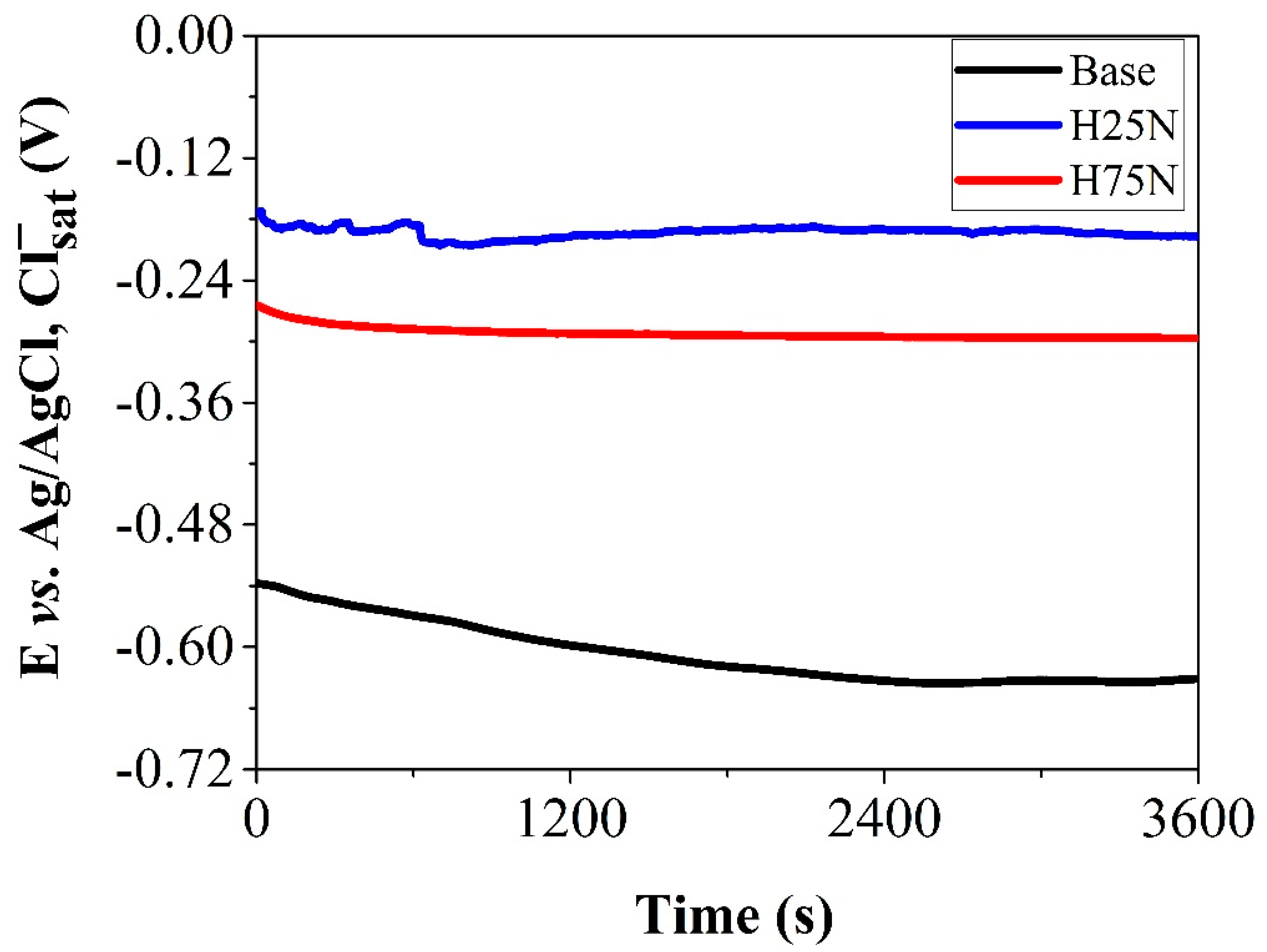
- Choudhary, S.; Garg, A.; Mondal, K. Relation Between Open Circuit Potential and Polarization Resistance with Rust and Corrosion Monitoring of Mild Steel. J. Mater. Eng. Perform. 2016, 25, 2969–2976. [Google Scholar] [CrossRef]
- Rossi, S.; Deflorian, F.; Zen, M.; Fedrizzi, L. Wear-Corrosion of Nitrided Steel: Corrosion Potential Monitoring to Evaluate the Effect of Test Parameters. Mater. Corros. 2000, 51, 552–556. [Google Scholar] [CrossRef]
- Borgioli, F.; Galvanetto, E.; Bacci, T. Corrosion Behaviour of Low Temperature Nitrided Nickel-Free, AISI 200 and AISI 300 Series Austenitic Stainless Steels in NaCl Solution. Corros. Sci. 2018, 136, 352–365. [Google Scholar] [CrossRef]
- Herrera Hernández, H.; Ruiz Reynoso, A.M.; Trinidad González, J.C.; González Morán, C.O.; Miranda Hernández, J.G.; Mandujano Ruiz, A.; Morales Hernández, J.; Orozco Cruz, R. Electrochemical Impedance Spectroscopy (EIS): A Review Study of Basic Aspects of the Corrosion Mechanism Applied to Steels. In Electrochemical Impedance Spectroscopy; El-Azazy, M., Min, M., Annus, P., Eds.; IntechOpen: London, UK, 2020; ISBN 978-1-78985-215-8. [Google Scholar]
- Boztepe, E.; Alves, A.C.; Ariza, E.; Rocha, L.A.; Cansever, N.; Toptan, F. A Comparative Investigation of the Corrosion and Tribocorrosion Behaviour of Nitrocarburized, Gas Nitrided, Fluidized-Bed Nitrided, and Plasma Nitrided Plastic Mould Steel. Surf. Coat. Technol. 2018, 334, 116–123. [Google Scholar] [CrossRef]
- Escobar, C.A.; Caicedo, J.C.; Aperador, W. Corrosion Resistant Surface for Vanadium Nitride and Hafnium Nitride Layers as Function of Grain Size. J. Phys. Chem. Solids 2014, 75, 23–30. [Google Scholar] [CrossRef]
- Brown, R.; Alias, M.N.; Fontana, R. Effect of Composition and Thickness on Corrosion Behavior of TiN and ZrN Thin Films. Surf. Coat. Technol. 1993, 62, 467–473. [Google Scholar] [CrossRef]
- McCafferty, E. Validation of Corrosion Rates Measured by the Tafel Extrapolation Method. Corros. Sci. 2005, 47, 3202–3215. [Google Scholar] [CrossRef]
- Esmailzadeh, S.; Aliofkhazraei, M.; Sarlak, H. Interpretation of Cyclic Potentiodynamic Polarization Test Results for Study of Corrosion Behavior of Metals: A Review. Prot. Met. Phys. Chem. Surf. 2018, 54, 976–989. [Google Scholar] [CrossRef]
- Schibicheski Kurelo, B.C.E.; De Souza, G.B.; Serbena, F.C.; Lepienski, C.M.; Borges, P.C. Mechanical Properties and Corrosion Resistance of αN-Rich Layers Produced by PIII on a Super Ferritic Stainless Steel. Surf. Coat. Technol. 2020, 403, 126388. [Google Scholar] [CrossRef]


| Sample | Temperature | Time | Gas Ratio | Pressure |
|---|---|---|---|---|
| H25N | 450 °C | 4 h | 25% N2 + 75% H2 | 260 Pa |
| H75N | 75% N2 + 25% H2 | 120 Pa |
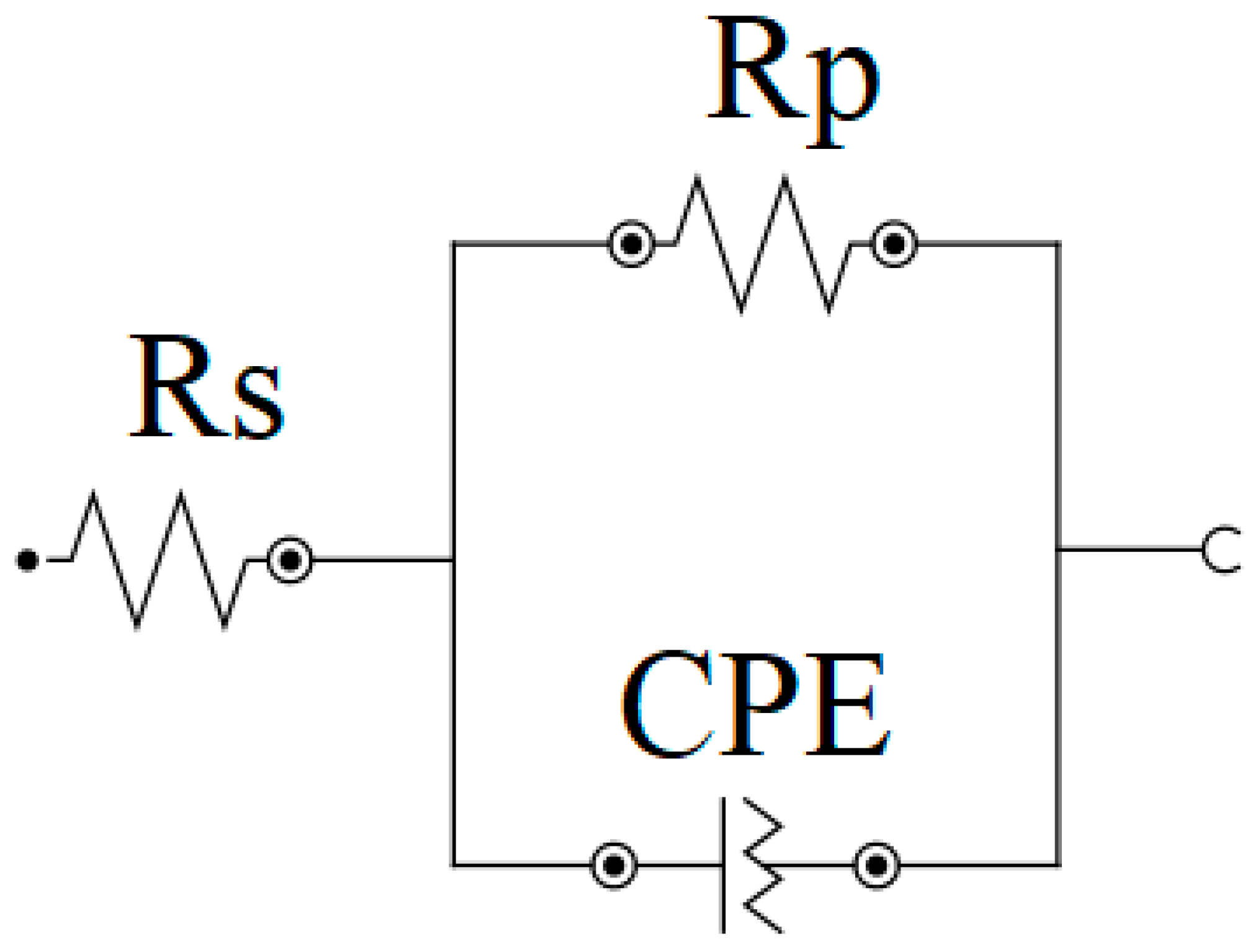
| Sample | Ecorr (mV) | Rs (Ω cm2) | CPE | Rp (kΩ cm2) | |
|---|---|---|---|---|---|
| Yo (µF cm−2 sn−1) | n | ||||
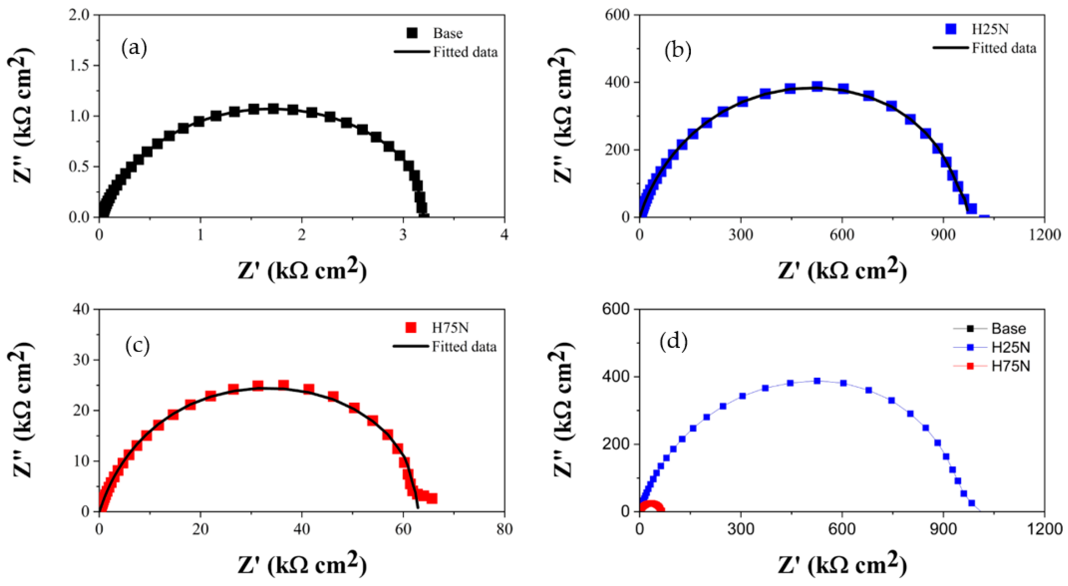
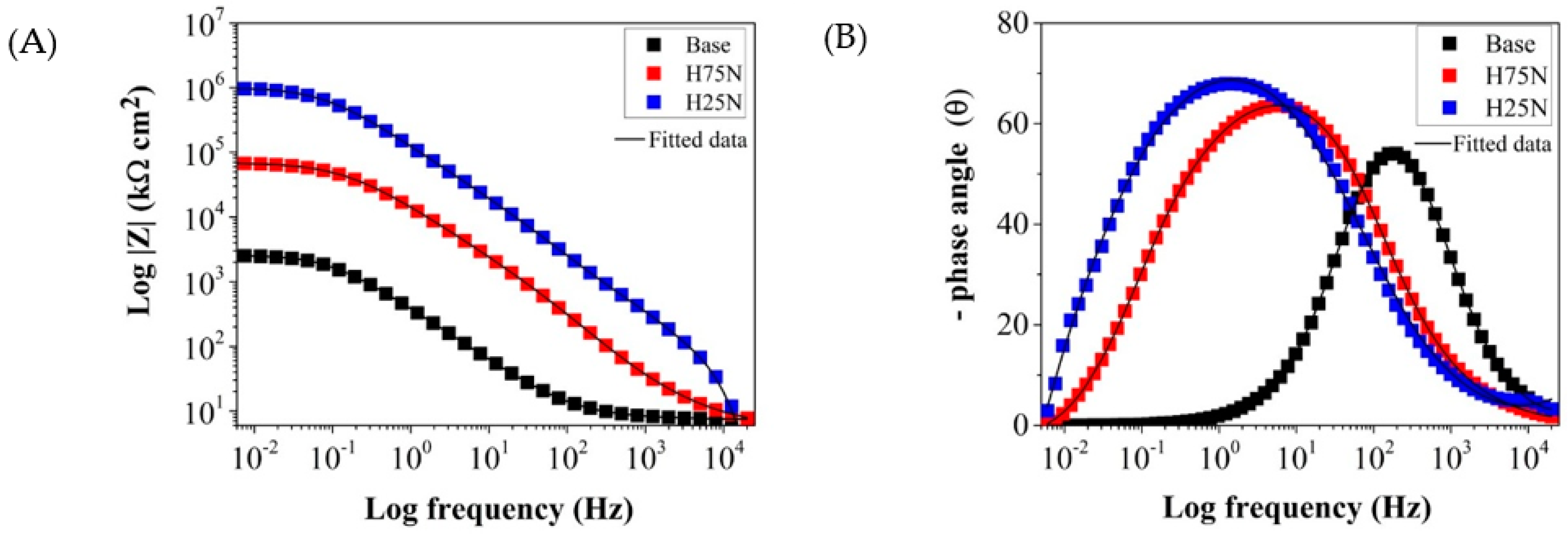
| Base | −630 ± 20 | 2.8 ± 2.1 | 42.75 ± 5.12 | 0.72 ± 0.02 | 3.28 ± 0.18 |
| H25N | −195 ± 15 | 2.5 ± 2.2 | 0.15 ± 0.06 | 0.88 ± 0.03 | 960.52 ± 0.34 |
| H75N | −295 ± 10 | 3.1 ± 2.3 | 0.43 ± 0.11 | 0.79 ± 0.02 | 62.02 ± 0.25 |
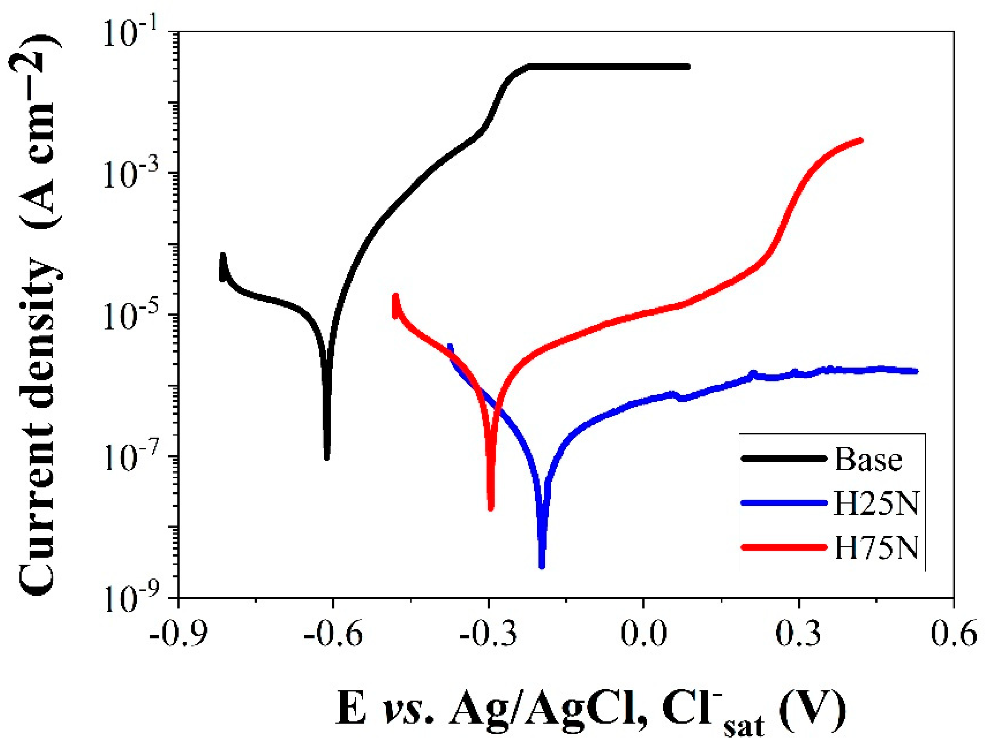
| Sample | Ecorr/mV | icorr/µA cm−2 |
|---|---|---|
| Base | −630 | 38.95 |
| H25N | −195 | 0.25 |
| H75N | −295 | 1.79 |
Disclaimer/Publisher’s Note: The statements, opinions and data contained in all publications are solely those of the individual author(s) and contributor(s) and not of MDPI and/or the editor(s). MDPI and/or the editor(s) disclaim responsibility for any injury to people or property resulting from any ideas, methods, instructions or products referred to in the content. |
© 2025 by the authors. Licensee MDPI, Basel, Switzerland. This article is an open access article distributed under the terms and conditions of the Creative Commons Attribution (CC BY) license (https://creativecommons.org/licenses/by/4.0/).
Share and Cite
Brito, M.C.d.S.; Pereira, J.C.; Silva, L.G.d.L.; Monção, R.M.; de Sousa, E.M.; Sampaio, W.R.V.; Nascimento, I.O.; de Araújo, A.Í.; Feitor, M.C.; Costa, T.H.d.C.; et al. Corrosion Resistance of SAE 5160 Steel Deposited by Duplex Simultaneous Treatment with Hastelloy Cathodic Cage. Lubricants 2025, 13, 177. https://doi.org/10.3390/lubricants13040177
Brito MCdS, Pereira JC, Silva LGdL, Monção RM, de Sousa EM, Sampaio WRV, Nascimento IO, de Araújo AÍ, Feitor MC, Costa THdC, et al. Corrosion Resistance of SAE 5160 Steel Deposited by Duplex Simultaneous Treatment with Hastelloy Cathodic Cage. Lubricants. 2025; 13(4):177. https://doi.org/10.3390/lubricants13040177
Chicago/Turabian StyleBrito, Marcos Cristino de Sousa, Juliermes Carvalho Pereira, Lauriene Gonçalves da Luz Silva, Renan Matos Monção, Ediones Maciel de Sousa, Weslley Rick Viana Sampaio, Igor Oliveira Nascimento, Anthunes Íkaro de Araújo, Michelle Cequeira Feitor, Thercio Henrique de Carvalho Costa, and et al. 2025. "Corrosion Resistance of SAE 5160 Steel Deposited by Duplex Simultaneous Treatment with Hastelloy Cathodic Cage" Lubricants 13, no. 4: 177. https://doi.org/10.3390/lubricants13040177
APA StyleBrito, M. C. d. S., Pereira, J. C., Silva, L. G. d. L., Monção, R. M., de Sousa, E. M., Sampaio, W. R. V., Nascimento, I. O., de Araújo, A. Í., Feitor, M. C., Costa, T. H. d. C., & de Sousa, R. R. M. (2025). Corrosion Resistance of SAE 5160 Steel Deposited by Duplex Simultaneous Treatment with Hastelloy Cathodic Cage. Lubricants, 13(4), 177. https://doi.org/10.3390/lubricants13040177