Article

Effect of Applied Current on Tribological Properties of Polyphenyl Ether

1
Graduate School of Science and Engineering, Kansai University, Osaka 564-8680, Japan
2
Faculty of Engineering Science, Kansai University, Osaka 564-8680, Japan
3
State Key Laboratory of Molecular Engineering of Polymers, Fudan University, Shanghai 200433, China
*
Author to whom correspondence should be addressed.
Lubricants 2025, 13(4), 173; https://doi.org/10.3390/lubricants13040173
Submission received: 25 March 2025 / Revised: 7 April 2025 / Accepted: 7 April 2025 / Published: 9 April 2025
(This article belongs to the Special Issue Synthetic Greases and Oils)

Abstract

:
The widespread adoption of electric vehicles (EVs) has introduced new challenges in drivetrain lubrication, particularly concerning electrical corrosion, frictional wear, and hydrogen embrittlement. While polyalphaolefin (PAO)-based lubricants are commonly used, they struggle under high-speed and high-torque conditions. In contrast, polyphenyl ether (PPE)-based lubricants offer superior wear resistance and effectively suppress hydrogen generation, making them promising for EV applications. This study examines the effects of current direction and magnitude on tribofilm formation and frictional behavior in a PPE-lubricated environment. The results show that PPE exhibits unique tribofilm adhesion characteristics influenced by electrical conditions, unlike PAO. Surface analysis reveals that the tribofilm mainly consists of amorphous carbon, and friction under an electrical bias induces PPE oxidation, with oxidation products forming more readily at the positive electrode. Tribofilm formation correlated with increased friction and wear, particularly under currents of 10 mA or higher. Although PPE is more sensitive to electrical influences than PAO, it exhibits excellent wear resistance and maintains a low coefficient of friction even under electrification. This suggests that PPE could be suitable for lubrication in electrical environments and may serve as a promising lubricant for EV drive systems and similar applications.

1. Introduction

With the rapid growth in EV usage, the lubrication conditions in drivetrains have become a significant challenge. In recent years, EV drivetrains have become increasingly miniaturized and integrated; the “E-Axle” system—an integrated unit combining the motor, inverter, and gearbox—is a representative example. The adoption of the E-Axle has led to the consolidation of lubrication systems as well. Traditionally, separate lubricants were used for each component (such as bearings and gears), but in an E-Axle the same lubricant is used to lubricate the bearings and gears and to cool the motor simultaneously [1,2,3]. As a result, the lubricant must perform both lubrication and protective functions while also providing cooling for the motor, all within a limited oil volume.
Under these integrated conditions, the lubricant is required to maintain stable tribological performance not only at high temperatures and pressures but also in the presence of electric fields [4,5,6,7,8]. Moreover, nascent (freshly exposed) steel surfaces led by surface wear are highly reactive and can induce the tribochemical decomposition of the lubricant [9,10,11]. In addition, hydrogen released from lubricant decomposition can accelerate hydrogen embrittlement in metal components, potentially reducing the rolling fatigue life of bearings [12,13,14,15]. These challenges impose performance requirements that conventional lubricants cannot fully meet, highlighting the need for new lubricants specifically designed for EV applications.
Currently, synthetic oils—particularly PAO-based lubricants—are widely used for EV drivetrain lubrication and cooling. PAO is favored as a drivetrain lubricant for its excellent resistance to thermal oxidation, good low-temperature fluidity, and high lubrication efficiency [16,17]. However, as EV technology advances, drivetrain systems are being subjected to higher rotational speeds and torques [18] along with further motor miniaturization and integration. These factors lead to phenomena such as shaft voltages and bearing currents that contribute to frictional wear and hydrogen embrittlement in bearings [19,20]. In particular, electrical discharge events (due to insulation breakdown in bearings) and lubricant degradation from electrical effects have become major concerns [21,22,23,24].
Recent research has therefore focused on developing new lubricants to meet these challenges. PPE-based lubricants, in particular, have demonstrated superior wear characteristics compared to PAO-based lubricants. Additionally, PPE maintains a stable performance at high temperatures while effectively suppressing hydrogen generation [25], making it a promising candidate for EV drivetrains. However, beyond polyol ester lubricants, researchers have also explored other alternative lubricants for electrified drivetrains. For instance, polyalkylene glycol (PAG) fluids and synthetic esters have been studied due to their high thermal stability and favorable dielectric properties [26]. Some formulations even incorporate silicone-based or phosphate ester oils as potential EV lubricants [27]. Additionally, ionic liquids have garnered attention as lubricant additives or replacements because of their non-flammability and tunable conductivity, though their compatibility and cost remain challenges [28]. Therefore, this study aims to comprehensively evaluate the performance of a PPE-based lubricant under harsh operating conditions with an applied electrical current. Specifically, reciprocating ball-on-disk friction tests were performed under various applied currents to examine the effects of current direction and magnitude on tribofilm formation and performance.

2. Materials and Methods

2.1. Lubricating Oil

PPE (polyphenyl ether) is an organic compound composed of multiple aromatic rings connected by oxygen atoms, and it is liquid at room temperature. Thanks to its excellent thermal stability and resistance to oxidation and radiation, PPE has been used as a base oil in lubricants and greases for high-temperature, high-radiation environments. However, PPE has the drawback of a low viscosity index. Nonetheless, the physical properties of PPE-based lubricants can be tuned by adjusting the length and number of alkyl chains attached to its molecular structure [29,30,31,32].
In this study, we used a monoalkyl tetraphenyl ether synthetic lubricant (MORESCO Corporation, Kobe, Japan) as the PPE-based oil. This lubricant’s molecule contains four benzene rings, three of which are connected by two ether linkages, and it has a single 16-carbon alkyl side chain. Based on this molecular configuration, it is designated as “R1-4P2E” in this work.
For comparison, a polyalphaolefin (PAO30, MORESCO Corporation, Kobe, Japan) base oil was also evaluated. PAO has a chemical composition similar to mineral oil but offers a high viscosity index and a low pour point, making it suitable for a broad temperature range. Furthermore, PAO can be formulated with conventional additives used in mineral oils, allowing for its use without modifications to existing lubrication systems or seal materials. PAO is also relatively cost-effective among synthetic lubricants, and as a result it is widely used in high-performance engine oils and various industrial lubricants.
Figure 1 illustrates the chemical structure of lubricants, and Table 1 presents their physical properties.

2.2. Tribological Tests

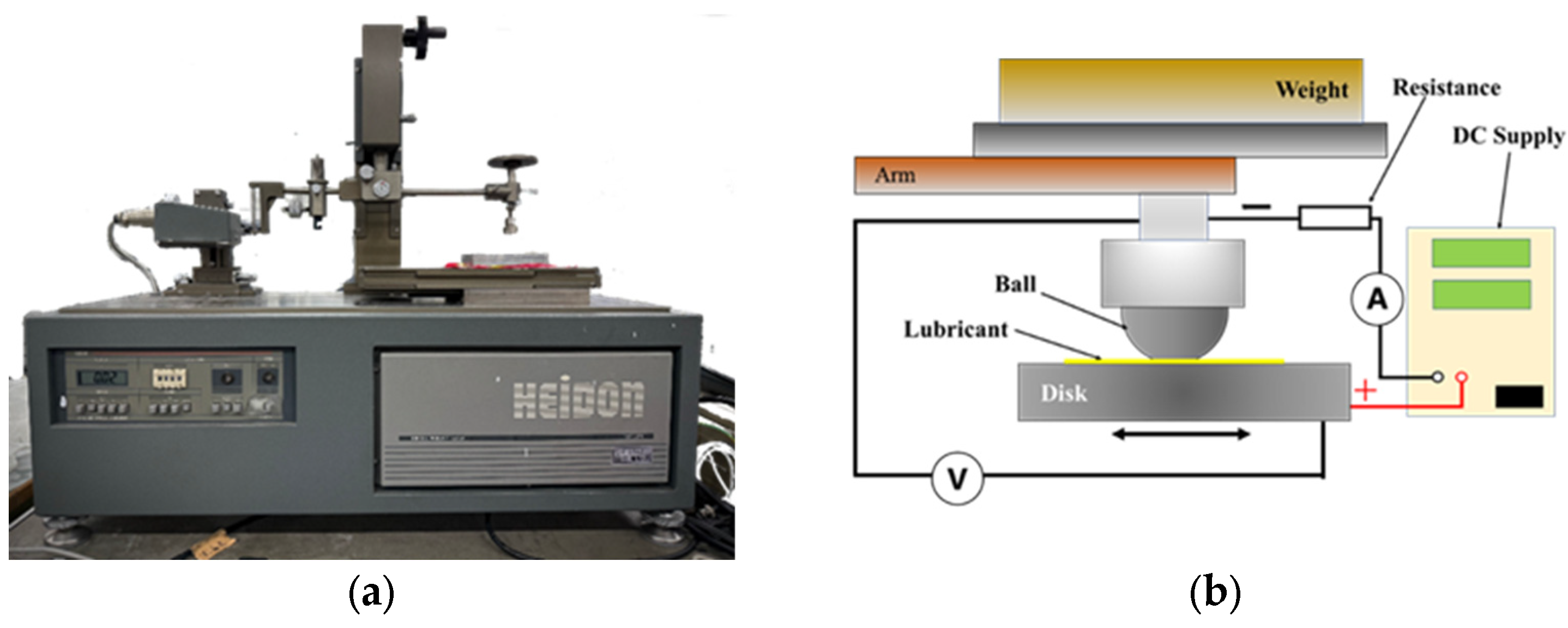
The coefficient of friction (COF) was measured using a reciprocating ball-on-disk tribometer (Heidon-14DR, Shinto Scientific Co., Ltd., Tokyo, Japan), as shown in Figure 2a. The ball used in the experiments was an AISI 52100 steel ball (diameter 6.35 mm, hardness HRC 65). An AISI 52100 steel disk (hardness HRC 63, surface roughness Ra 0.015 µm) was used as the mating specimen.
The test conditions were as follows: applied load, 5 N; reciprocating sliding speed, 8.0 mm/s; stroke length, 4 mm; and test duration, 1 h. These parameters were selected to mimic severe boundary lubrication conditions in EV drivetrain contacts, ensuring observable wear and tribofilm formation within a one-hour test. All tests were conducted at room temperature (23 ± 2 °C), 45–55% relative humidity, and repeated three times. During testing, a DC stabilized power supply provided the electrical current (with applied current levels varying from −80 mA to +80 mA in different tests), and measures were taken to electrically isolate the test rig. A polyimide insulating film was placed under the specimen holder base to prevent current from flowing to any part of the apparatus other than the sample specimens. Additionally, the shaft holding the ball was wrapped with an insulating film to ensure the ball was electrically isolated from the rest of the machine.

2.3. Characterization

After completing the friction tests, the ball and disk specimens were cleaned with hexane to remove excess lubricant. The resulting wear scars on both specimens were observed using a confocal laser scanning microscope (OLS5000, Olympus, Tokyo, Japan) to evaluate wear size and appearance.
Furthermore, the tribofilms on the wear scars were analyzed by micro-Raman spectroscopy (XploRA, Horiba Ltd., Kyoto, Japan). The measurements utilized a 532 nm wavelength laser with a 1% optical filter (neutral density) to avoid damaging the sample.
For compositional analysis, time-of-flight secondary ion mass spectrometry (ToF-SIMS 5, IONTOF GmbH, Münster, Germany) was performed. Spectra were acquired using a Bi3++ primary ion source, scanning a 50 µm × 50 µm area at a 256 × 256 pixel resolution, and accumulated over 32 scans. No sputtering/etching was applied before or during the ToF-SIMS analysis to ensure the natural tribofilm chemistry was preserved.
Additionally, X-ray photoelectron spectroscopy (XPS) was conducted on the worn disk surface to examine the chemical state of the tribofilm. A PHI X-tool scanning X-ray microprobe (ULVAC-PHI, Kanagawa, Japan) was used with monochromatic Al Kα radiation (26 W, 15 kV) to excite photoelectrons for high-resolution spectra.

3. Results and Discussion

3.1. Friction Test Results

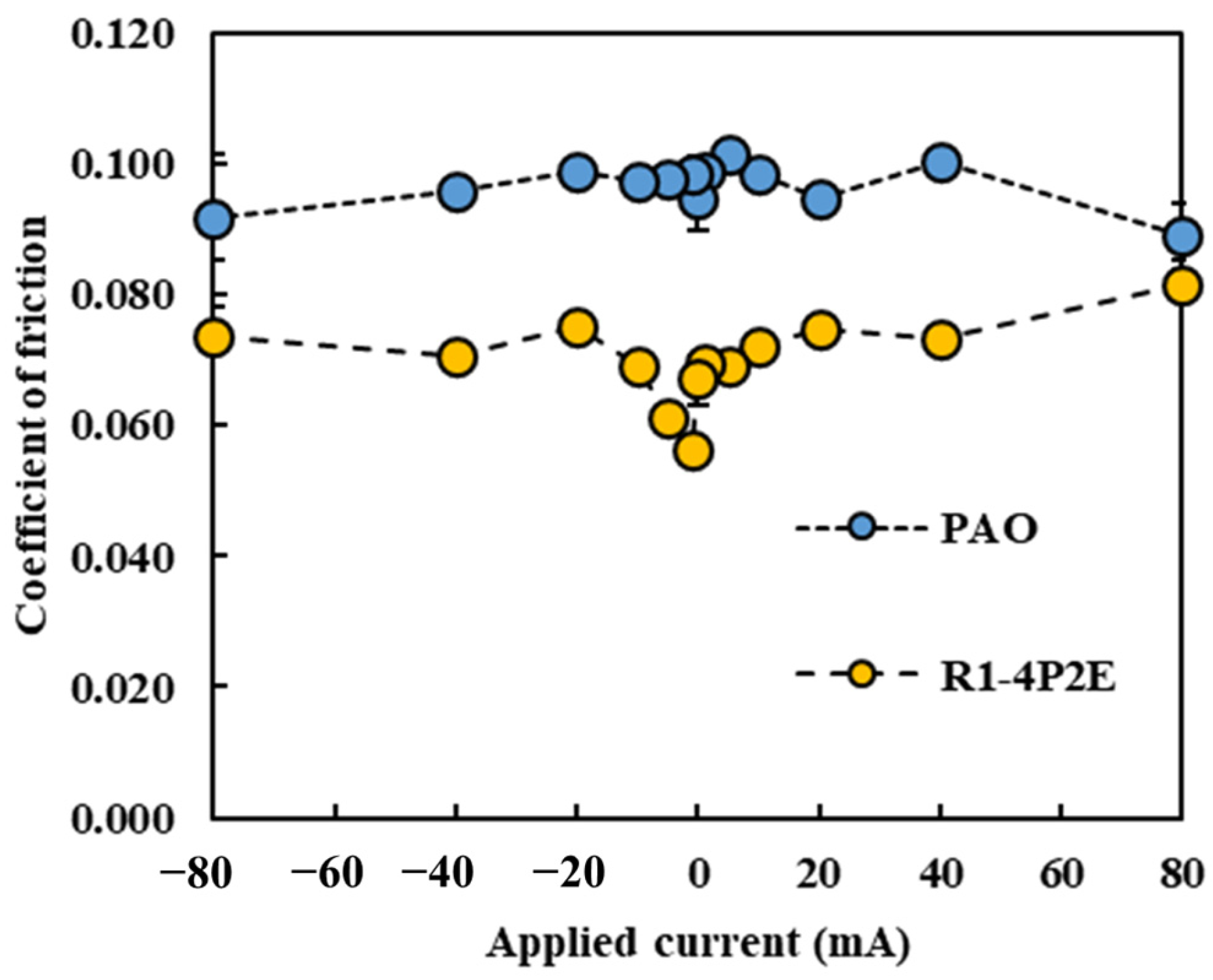
As shown in Figure 3, the effect of current direction and magnitude on the average COF was evaluated. The COF values reported are steady-state values, obtained by averaging the data from the last 10 min of each test (after the running-in period). In all cases, the sign of the applied current is defined from the perspective of the ball (i.e., a “+” current means the ball is the positive electrode).
Under all the tested current conditions, the PPE-based lubricant (R1-4P2E) exhibited a lower COF than the PAO. This trend is consistent with previous findings [25] reporting that PPE-based lubricants significantly reduce friction compared to PAO. Within the current range of approximately −10 mA to +10 mA, R1-4P2E maintained a COF of about 0.06–0.07, which was 30–40% lower than that of the PAO (~0.10). However, for current values exceeding 10 mA, a notable increase in COF was observed for R1-4P2E. For example, at +20 mA the COF increased by approximately 10% relative to the 0 mA (non-electrified) condition, and at +80 mA it increased by roughly 25%. Furthermore, the rise in COF was more pronounced when the ball was the positive electrode. At +20 mA, the COF with the ball being positive was higher than the COF with the ball being negative, suggesting that current polarity has a significant influence on friction behavior.
These effects became evident at around a 10 mA threshold. Below ~10 mA, R1-4P2E retained its low-friction performance, whereas above ~10 mA the influence of current on friction became significant. By contrast, the PAO lubricant showed minimal variation in COF across all tested current conditions, maintaining a stable COF of approximately 0.10 regardless of whether a current was applied. These observations suggest that PAO’s frictional behavior was essentially unaffected by electrical current, whereas R1-4P2E’s frictional behavior changed significantly with the magnitude and direction of the current. It is evident that PPE-based lubricants are more susceptible to applied electrical current than PAO. Still, within the ±10 mA range, R1-4P2E consistently showed low friction coefficients.
Previous studies have suggested that PPE molecules can form polymeric tribofilms during friction, which helps to reduce friction [25]. The findings of this study support this hypothesis: under moderate current conditions, a thin tribofilm derived from PPE forms on the contact surfaces, which contributes to lubrication and helps maintain a low friction coefficient. However, once the applied current exceeded roughly 10 mA, the excessive formation and accumulation of tribofilm began to adversely affect friction, causing the COF to rise beyond the baseline. (This aspect is further discussed in Section 3.3.)
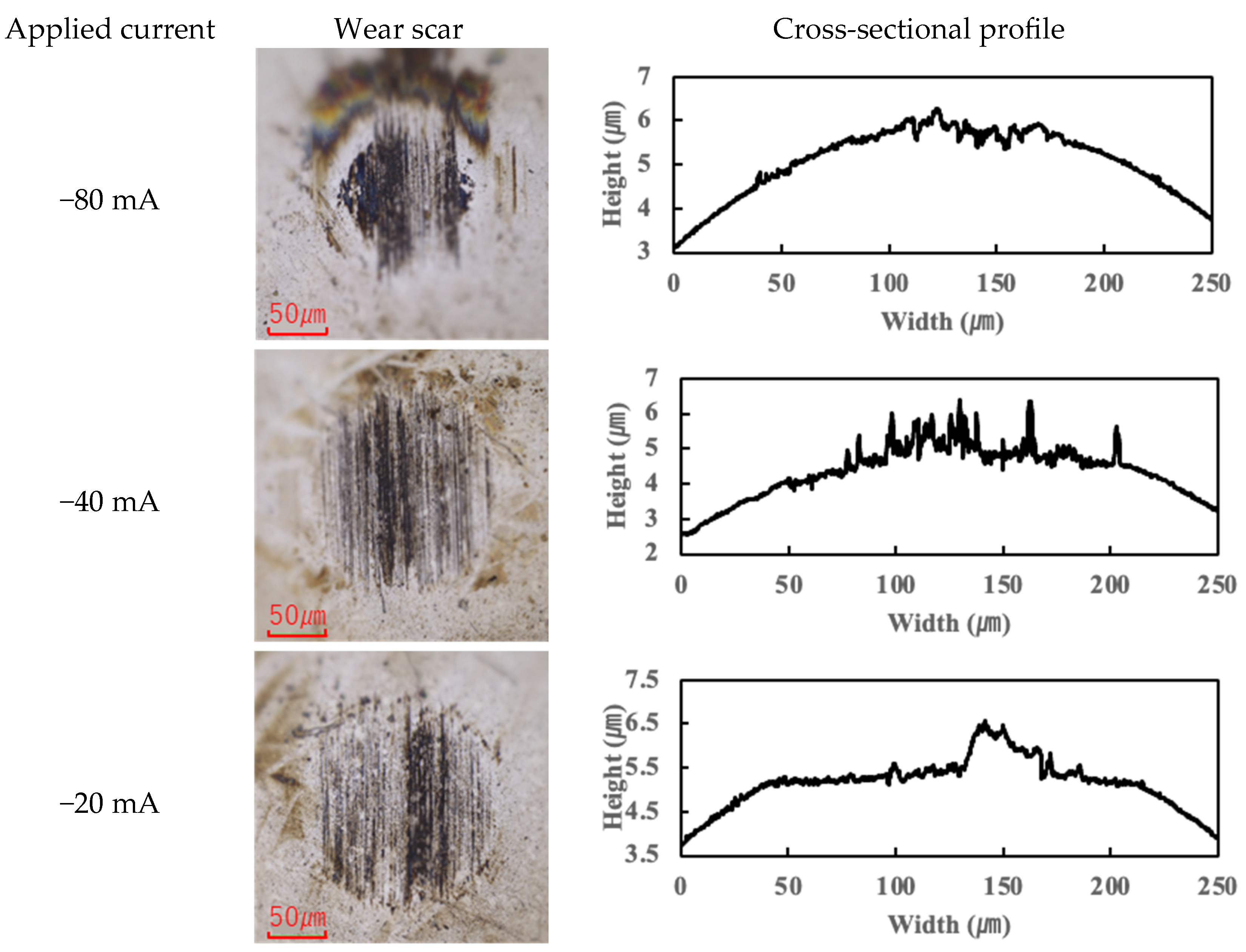
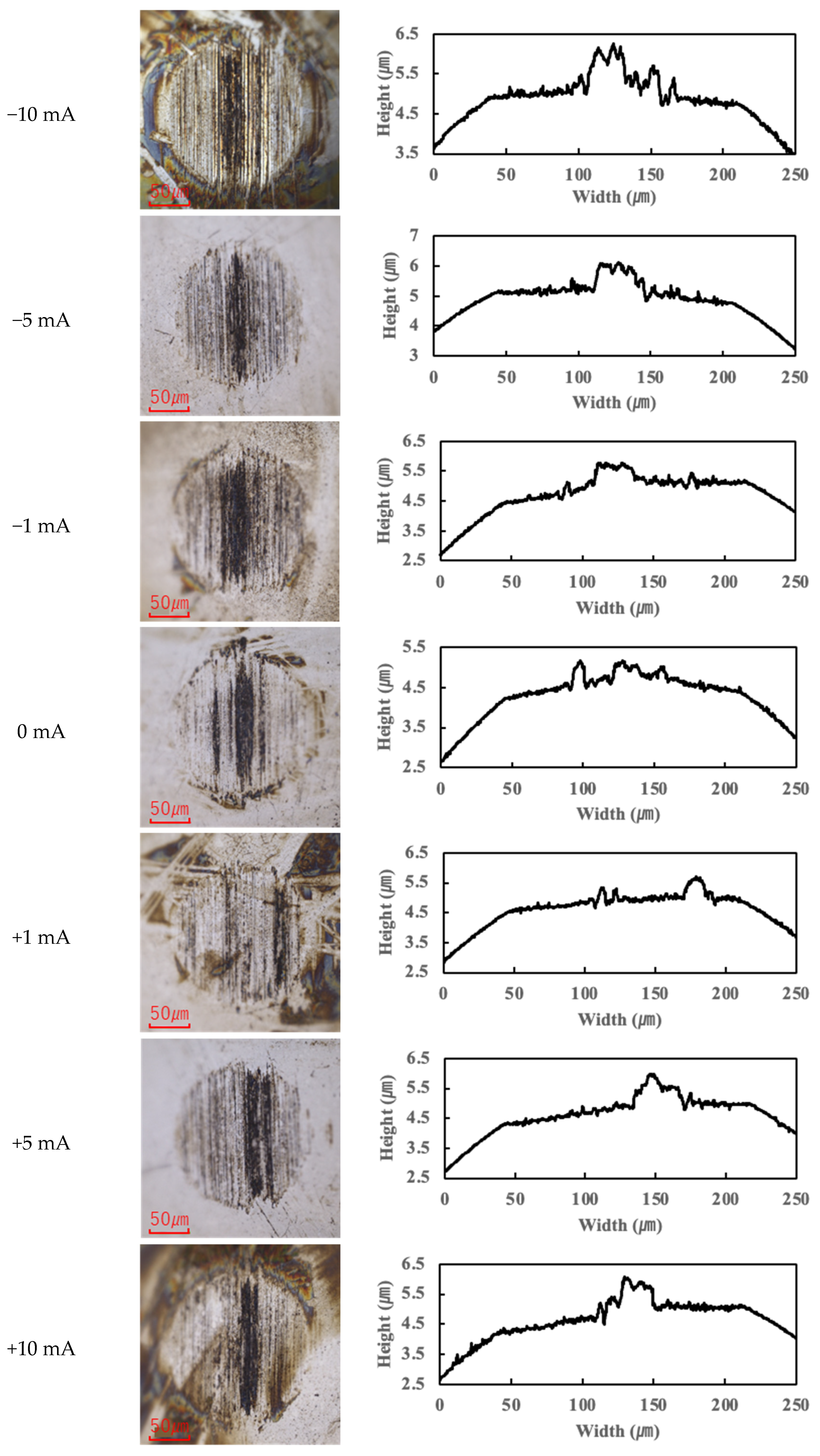
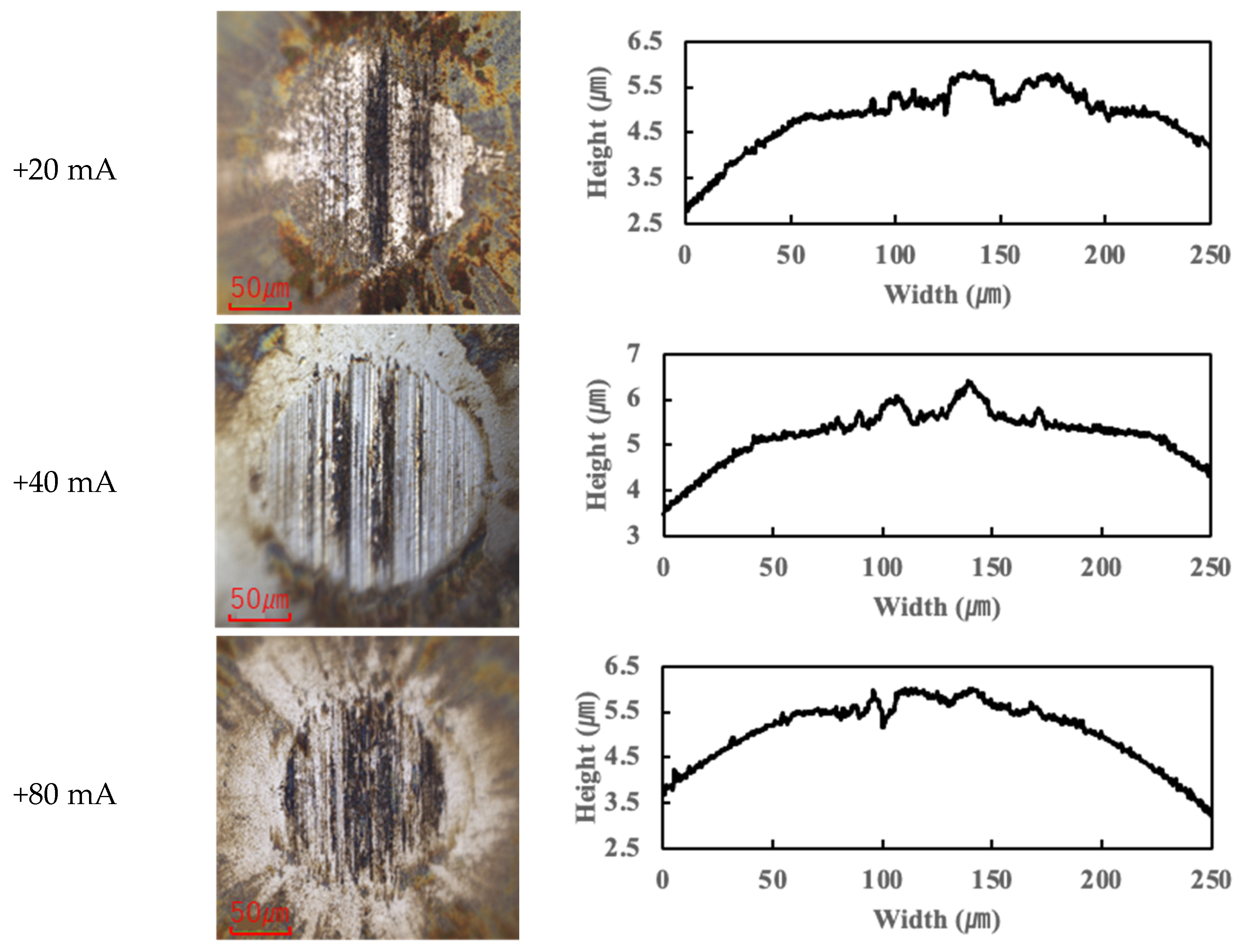
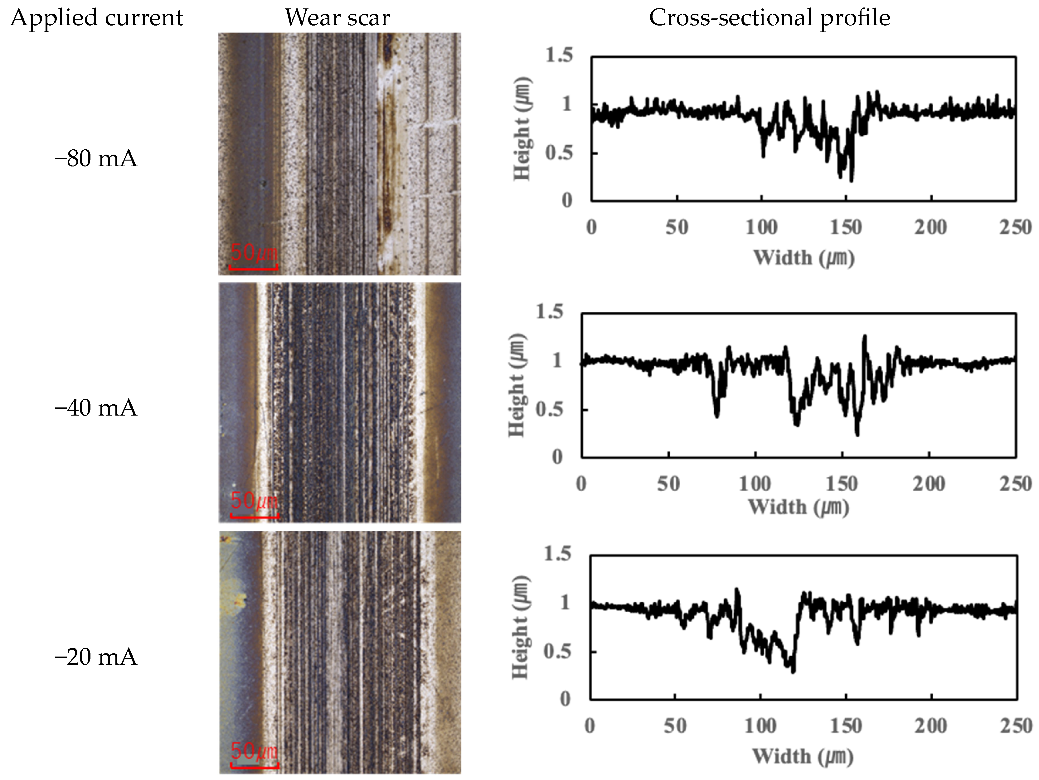
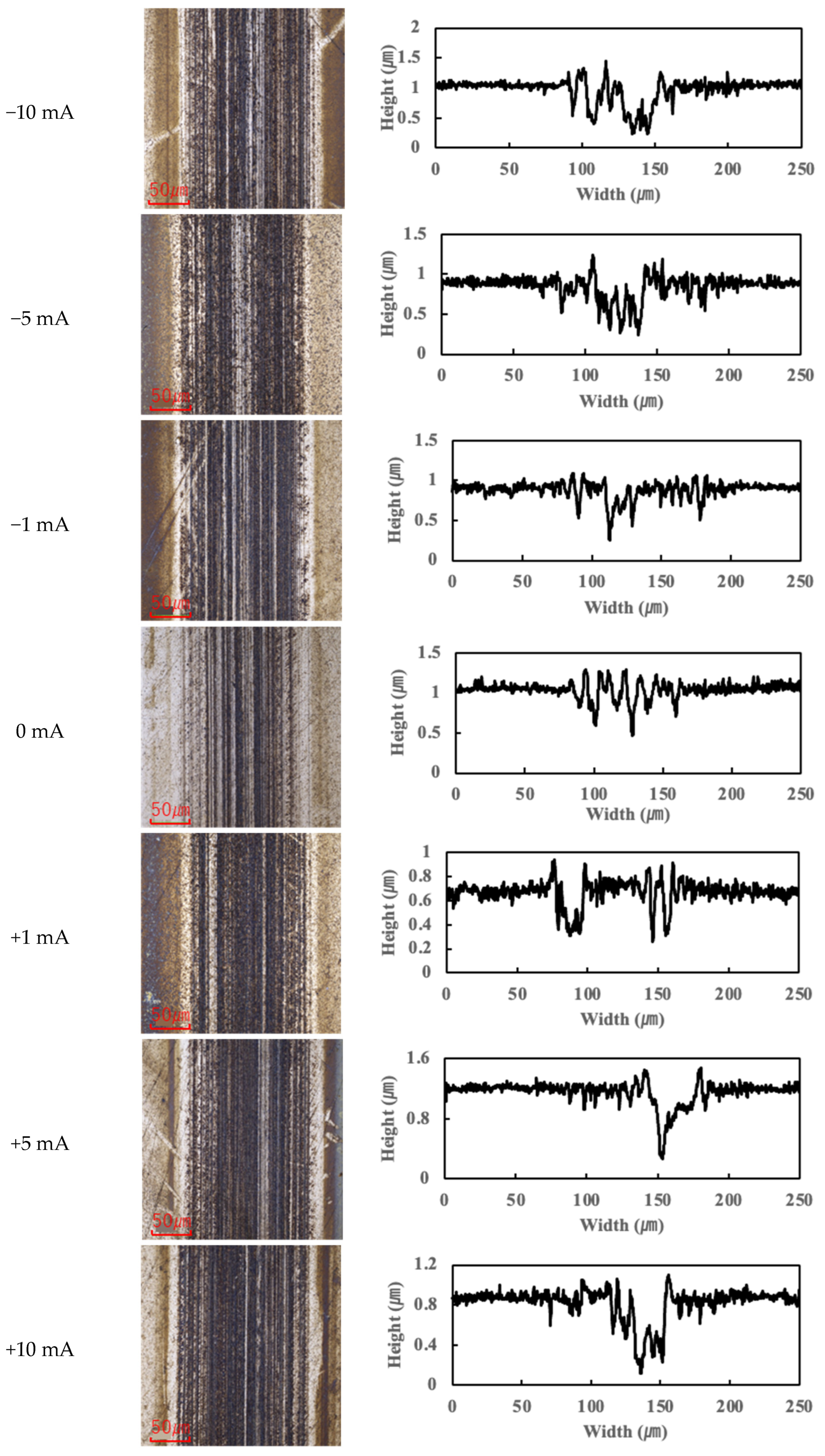
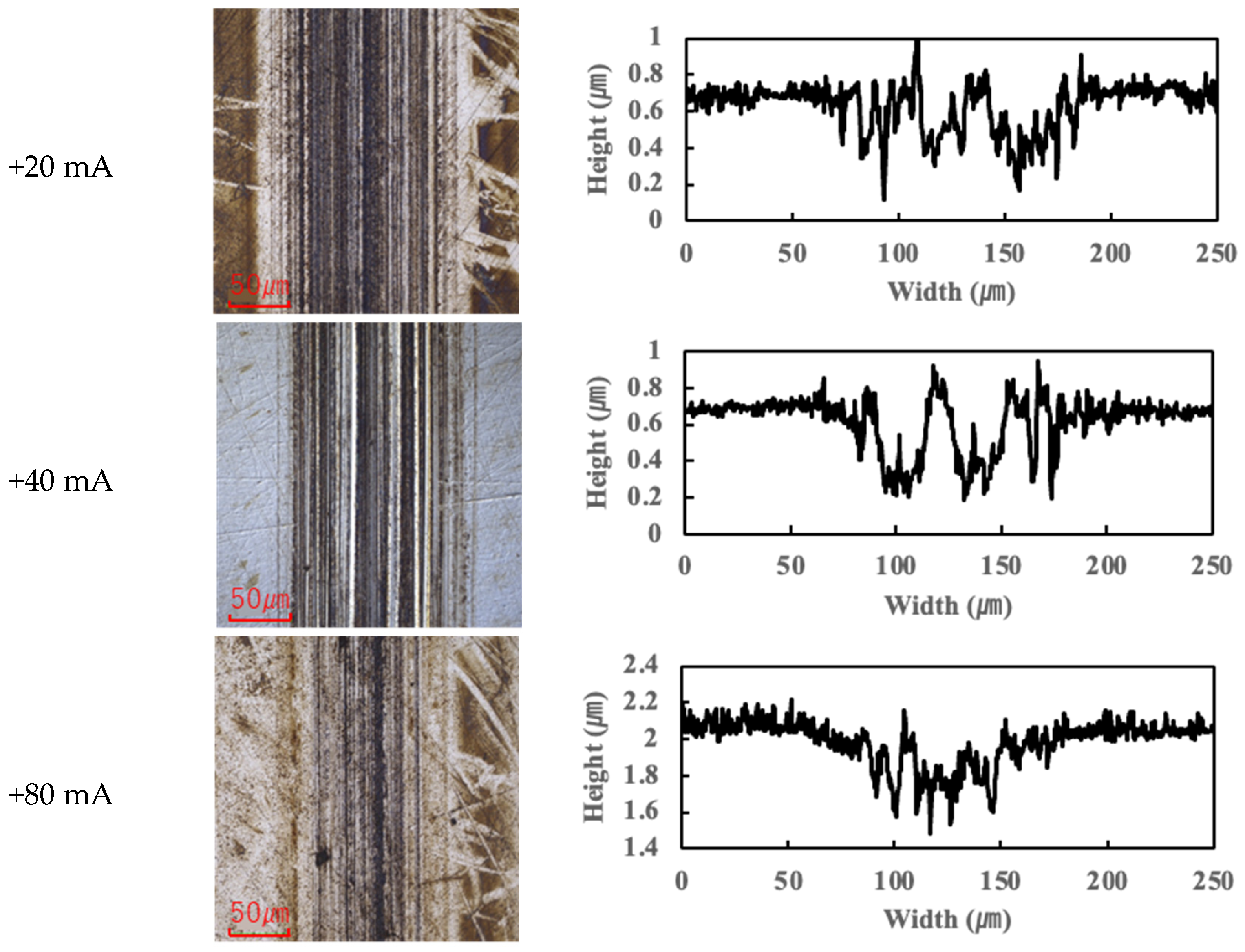
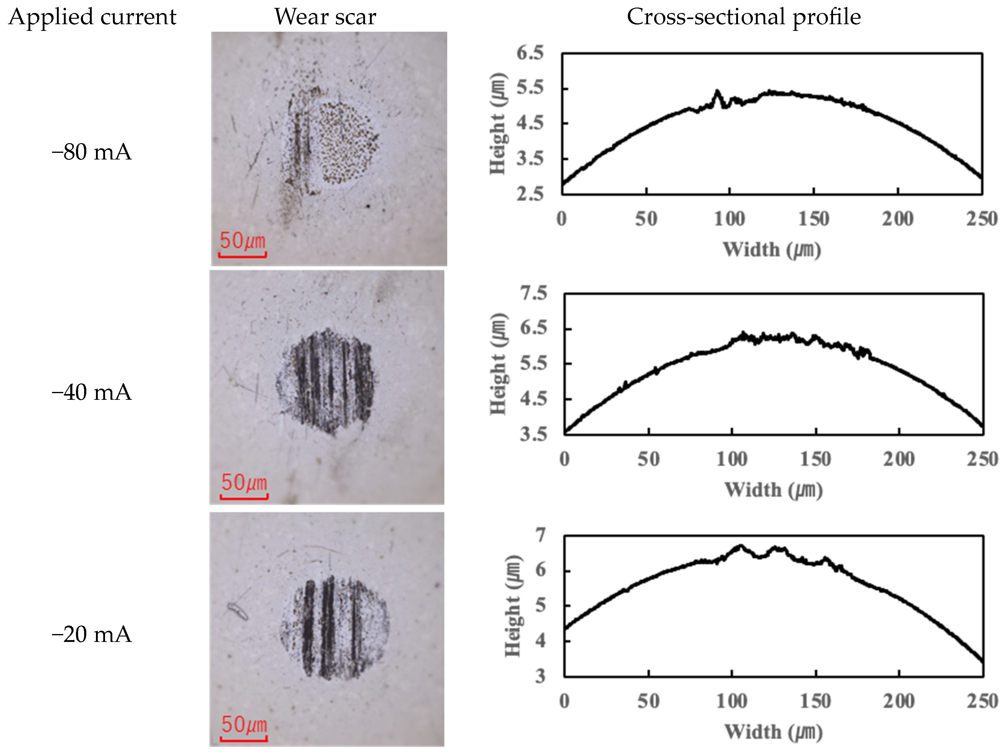
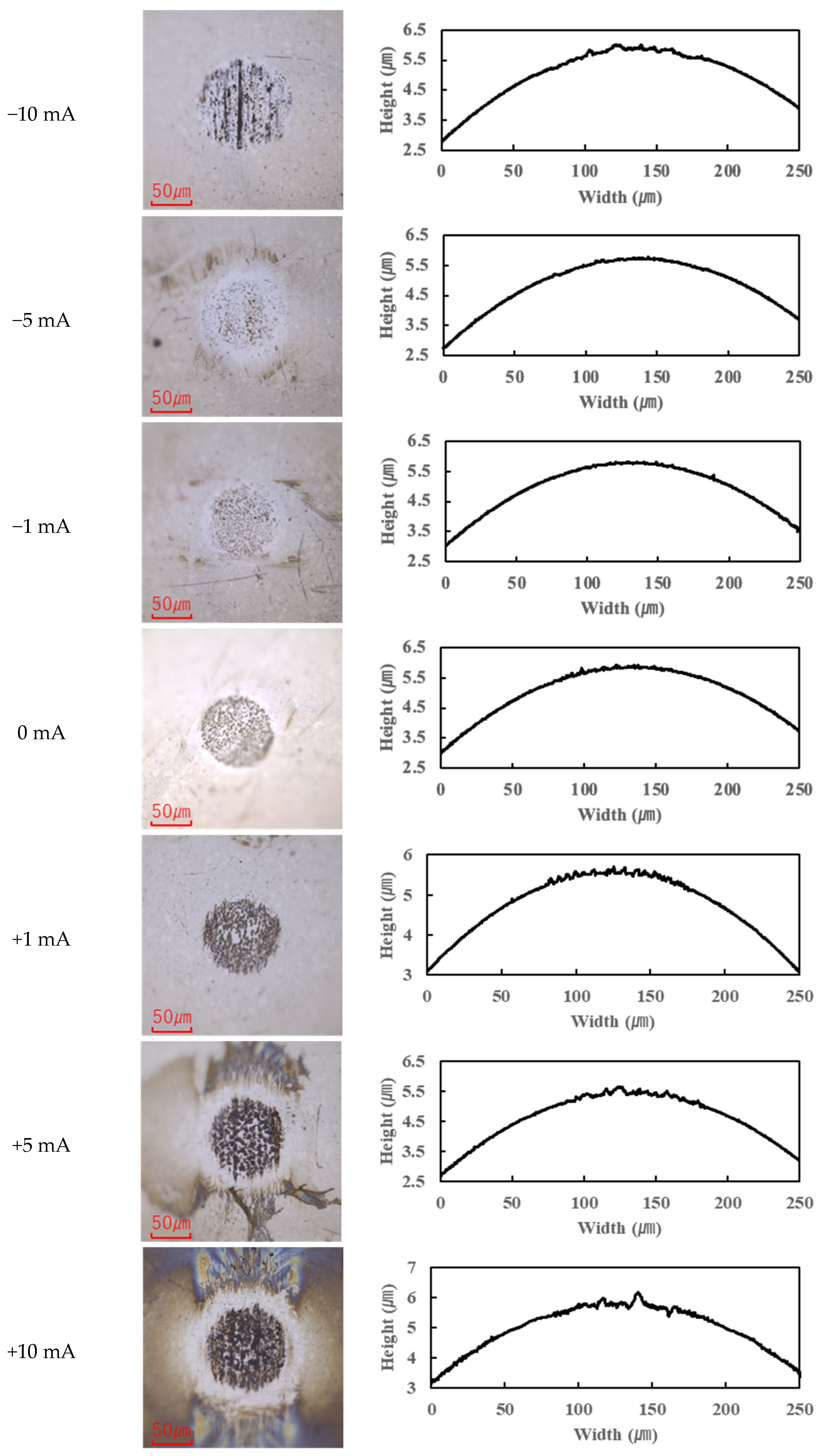
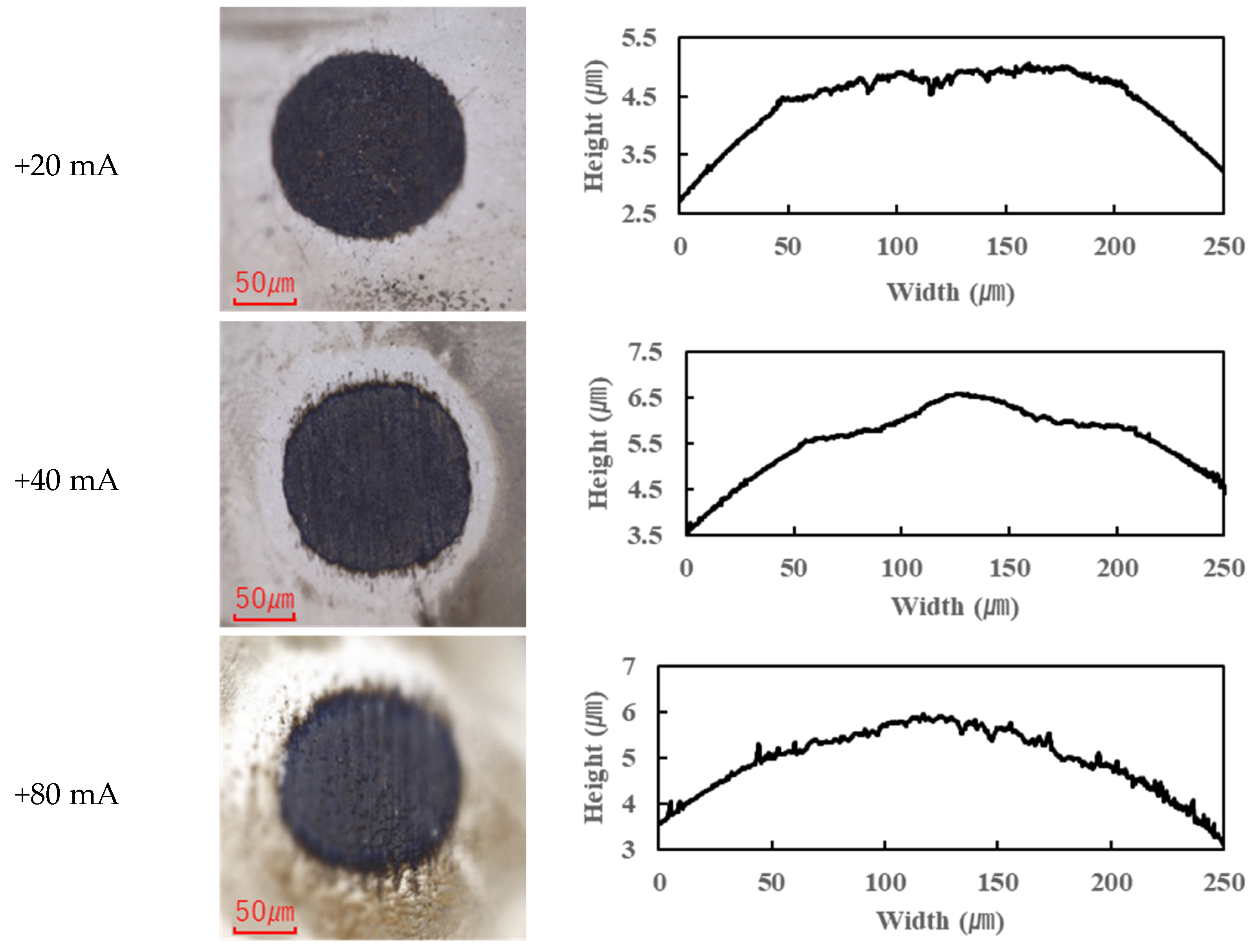
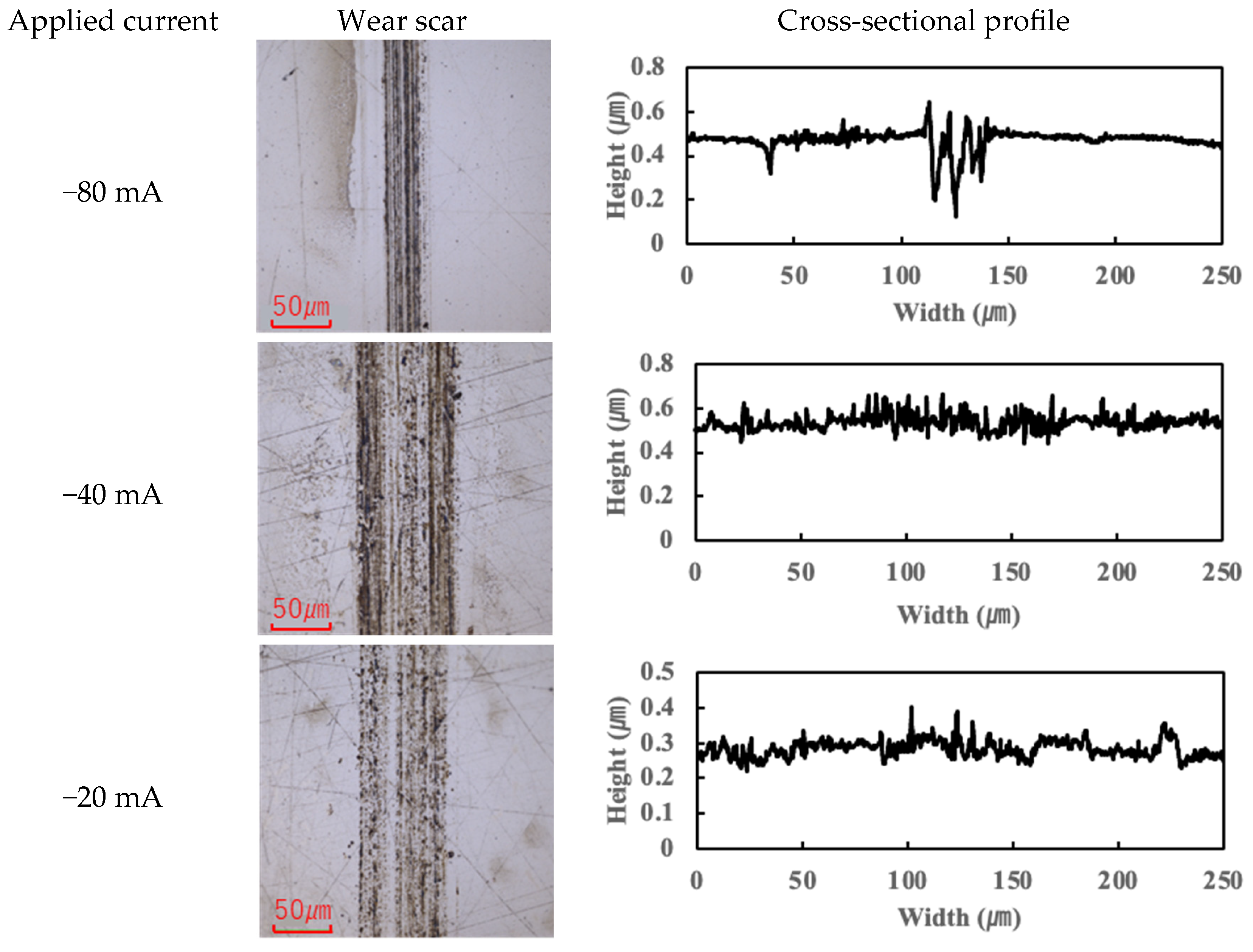
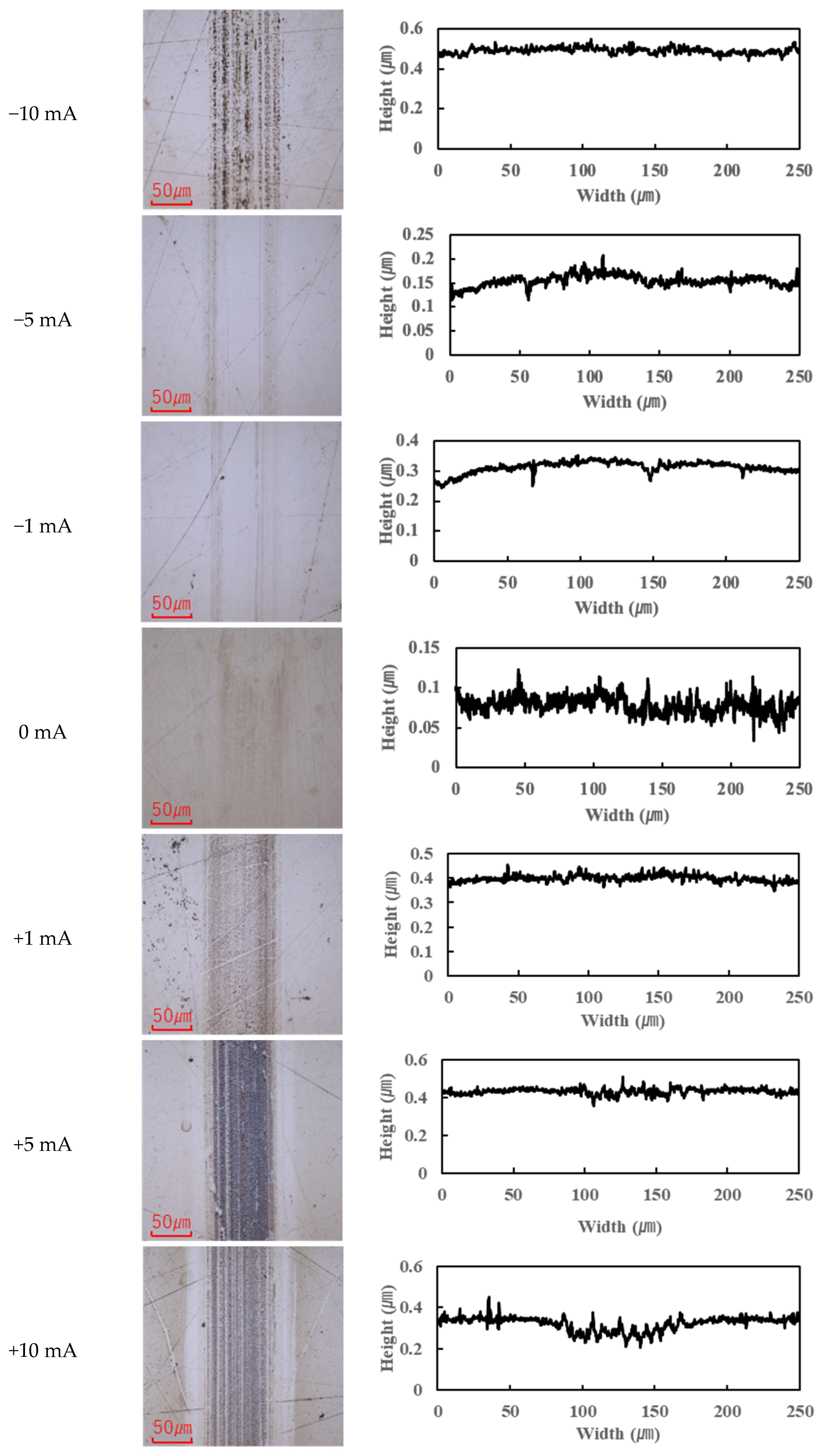
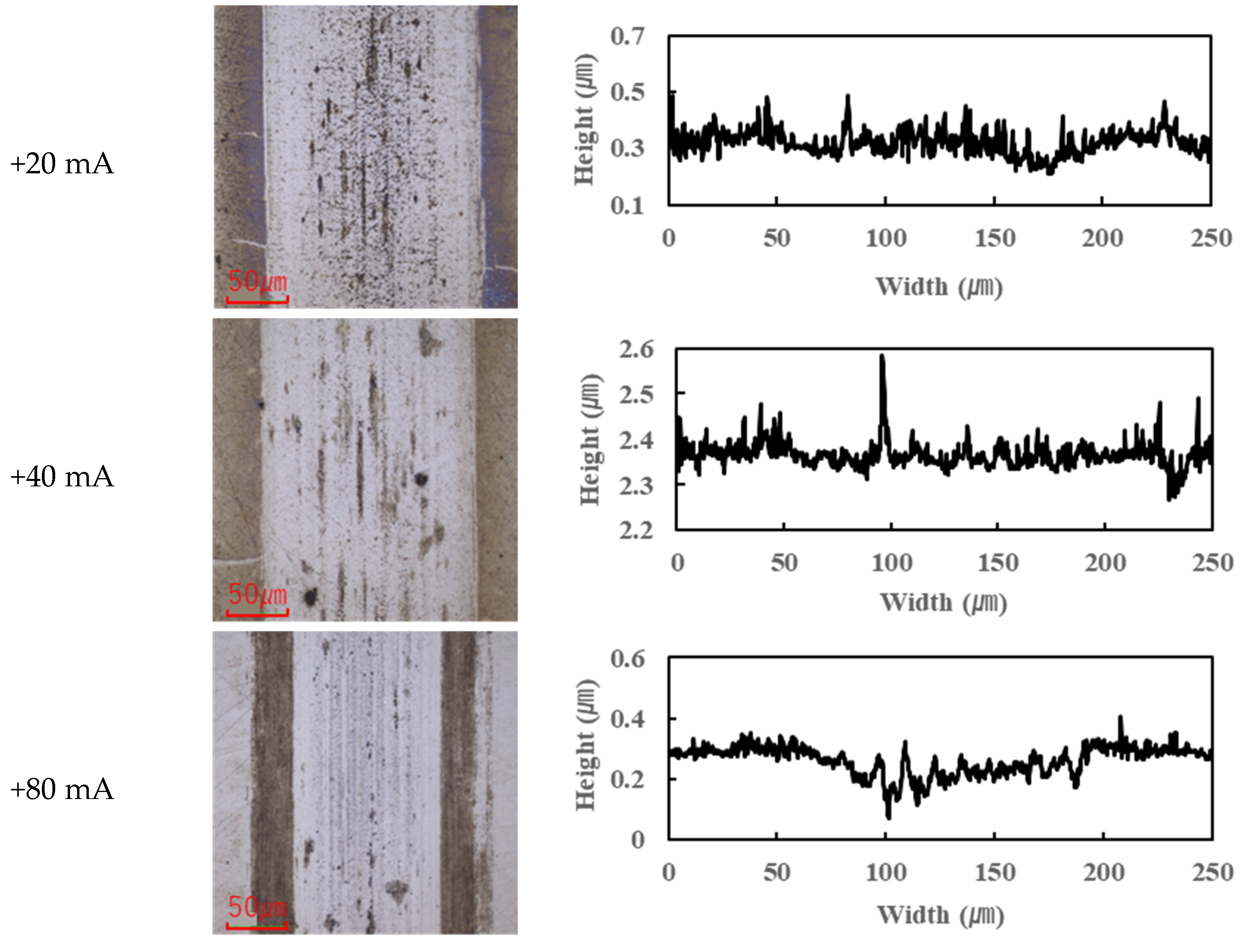
The application of current also affected wear. Figure 4, Figure 5, Figure 6 and Figure 7 present the wear scars and surface profiles of the ball and disk under different current conditions. The PAO tests showed almost no change in wear scar appearance across the range of currents. The wear scars with PAO lubrication remained bright and metallic in appearance, with only the minor localized attachment of wear debris. As seen in Figure 4 and Figure 5 (PAO and ball and disk, respectively), varying the current direction or magnitude did not produce any significant difference in scar color or condition, and no distinct tribofilm layer was evident (apart from a small amount of scattered debris).
In contrast, the PPE-based lubricant (R1-4P2E) resulted in smaller wear scars than the PAO, confirming its superior wear resistance, but it also produced noticeable black tribofilms on the wear surfaces. The extent of tribofilm adhesion with R1-4P2E varied markedly with the applied current. When using R1-4P2E, a black tribofilm formed on the ball’s wear scar under certain conditions, and its amount and coverage depended on current magnitude and polarity. Notably, tribofilm adhesion was much more pronounced on the positively charged surface. Under high-current conditions (approximately +20 mA to +80 mA) with the ball as the positive electrode, the entire wear scar on the ball was covered by a thick black tribofilm (Figure 6). This adhesive layer was substantial enough to be visible to the naked eye, forming a coating over the ball’s contact area. In the same +20 to +80 mA tests, the opposing disk (which was negative in this scenario) showed almost no adhesion; its wear track remained shiny and metallic with little to no black film (Figure 7).
For the reverse polarity (ball negative, disk positive) at high currents, the tribofilm distribution flipped: only a very thin film appeared on the ball’s wear scar (with the ball now being the negative electrode—see Figure 6), while a much thicker tribofilm adhered to the disk’s wear scar (Figure 7). These results clearly indicate that tribofilm formation is strongly biased towards the positively charged surface and suppressed on the negatively charged side. Under no-current or low-current (≤10 mA) conditions, any tribofilm formed with R1-4P2E was extremely thin; the wear scars in those cases remained largely clean metal with minimal visible film.
The presence or absence of tribofilm had a direct impact on wear volume. Figure 8 summarizes the wear scar size as a function of current for both lubricants (here represented by the ball wear scar diameter, which correlates with wear volume). Under no-current and ball-negative conditions, R1-4P2E consistently produced very small wear scars, demonstrating excellent wear resistance. This can be attributed to R1-4P2E’s ability to form a high-viscosity lubricating film that maintains a stable separation between the sliding surfaces, thereby suppressing wear. However, when the ball was positive under high current, the excessive accumulation of black tribofilm led to a significant increase in wear scar diameter—nearly approaching the wear size observed with PAO. In cases where the disk was positive (ball-negative), tribofilm built up preferentially on the disk; since the disk’s contact with the ball is intermittent (as the ball reciprocates), the tribofilm growth in that scenario was less extensive than in the ball-positive case. In general, excessive tribofilm formation created a thick, wide interfacial layer that increased the effective contact area and accelerated wear. This corresponds with the increase in COF observed in the +20 mA to +80 mA range, as a heavier tribofilm can disrupt smooth sliding and contribute to higher friction.

3.2. Surface Analysis

After the tribological tests, various surface analytical techniques were employed to elucidate the tribofilms’ composition and formation mechanisms. The analyses focused on characterizing the chemical species present in the tribofilms for R1-4P2E, especially under electrified conditions.

3.2.1. Raman Analysis

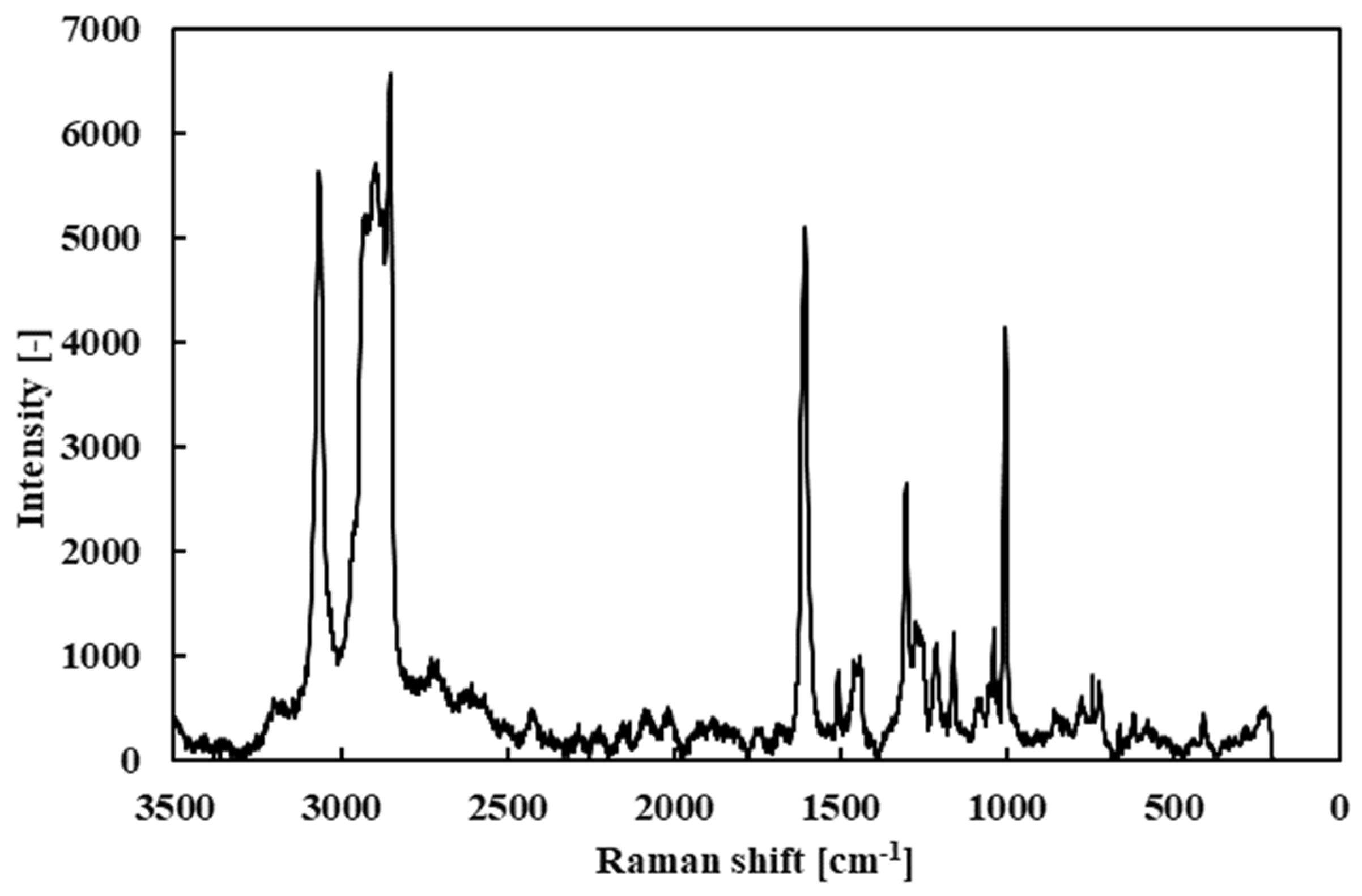
First, the Raman spectrum of the fresh R1-4P2E lubricant (liquid) was measured as a baseline (Figure 9). The spectrum showed prominent peaks near 3000 cm−1 (attributed to C–H stretching vibrations of alkyl groups), around 1600 cm−1 (C=C stretching vibrations from the aromatic rings), and near 1000 cm−1 (C–H bending vibrations). These peaks confirm the presence of vibrational modes characteristic of PPE’s molecular structure.
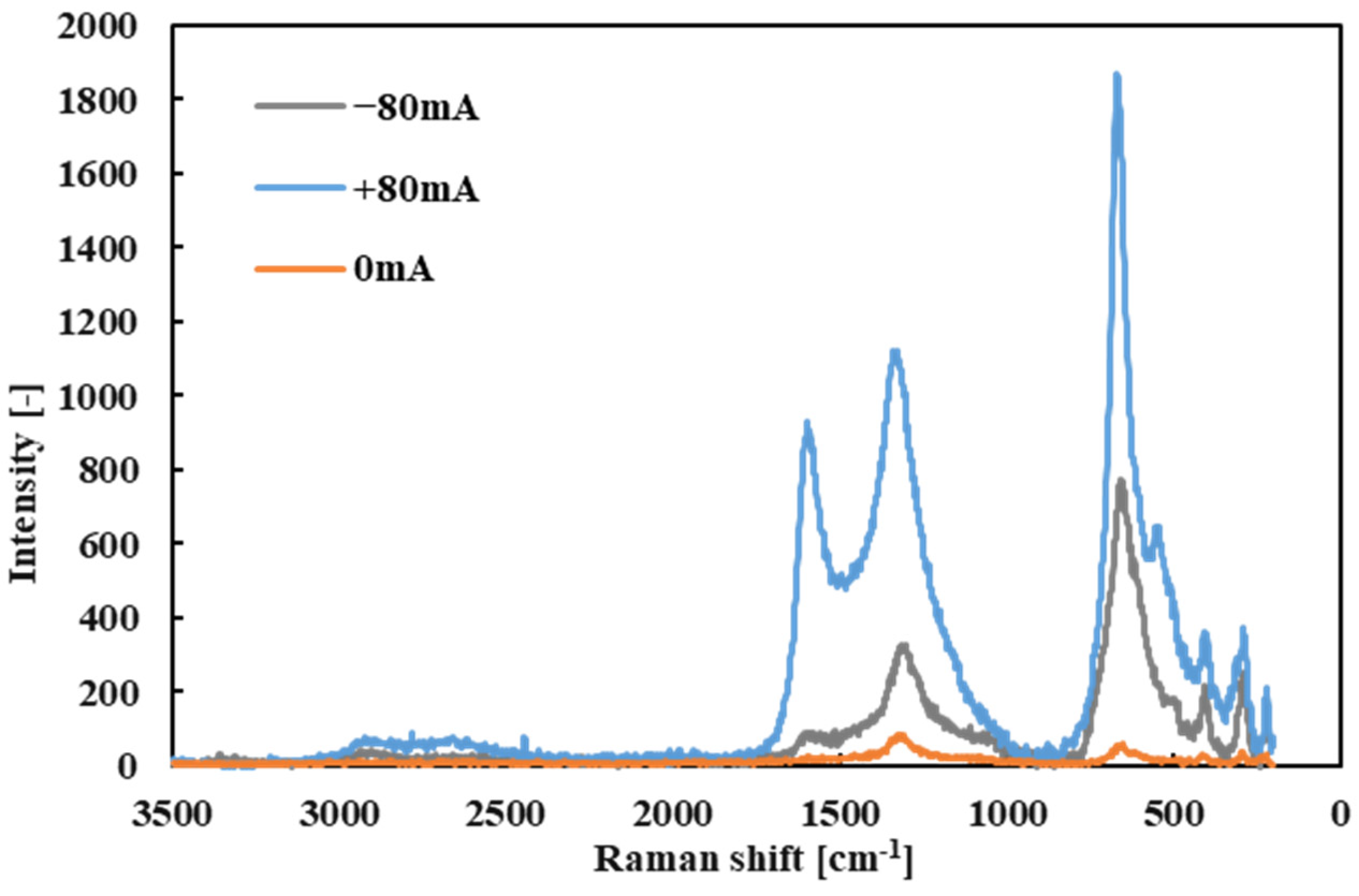
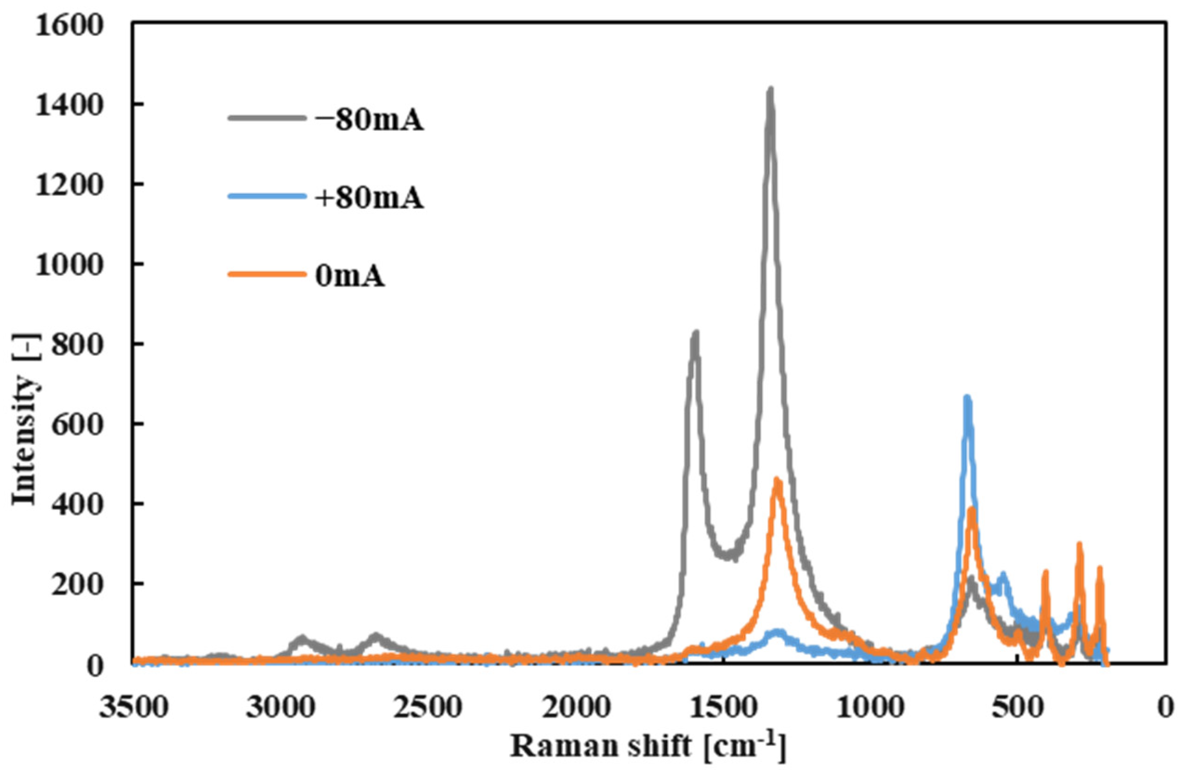
Subsequently, point Raman analyses were performed on the black tribofilms that formed on the wear scars of both the ball and the disk after testing with R1-4P2E (Figure 10 and Figure 11). Several distinct Raman bands were detected in the tribofilm spectra, with prominent peaks at approximately 222, 290, 408, 541, 666, and 1330 cm−1. These peaks correspond to characteristic Raman signals of hematite (α-Fe2O3)—an iron oxide—indicating that iron oxide particles are present in the tribofilm. In particular, the peaks at 222, 290, 408, 541, and 666 cm−1 match known modes of α-Fe2O3 [33,34]. Additionally, a broad band around 1330 cm−1 was observed; this was the D-band, characteristic of disordered (amorphous) carbon [25,35]. The presence of a strong D-band suggests that a carbonaceous component (from the thermal-/pressure-induced decomposition of the PPE lubricant) is a major part of the tribofilm.
Under certain conditions, an additional peak appeared near 1590 cm−1 in the tribofilm spectrum. This peak corresponds to the G-band, indicative of graphitic carbon structures [25,35]. Notably, the G-band was most evident in tribofilms formed when the electrode was positive on that specimen (for example, the ball at +80 mA vs. disk at −80 mA scenario). The appearance of the G-band implies that, under those high-current conditions, the tribofilm contained a degree of graphitized carbon in addition to amorphous carbon.
These Raman results indicate that the tribofilm formed in PPE lubrication consists of a mixture of iron oxides (hematite) and carbonaceous materials derived from the lubricant (predominantly amorphous carbon, with some graphitic carbon under specific conditions). Moreover, the spatial distribution of Raman intensity revealed a strong polarity effect. During tests with applied current, Raman signals for iron oxide and carbon were significantly stronger on the positively charged specimen surface. This confirms that the tribofilm formed preferentially on the positive electrode surface and accumulated there. This observation is consistent with the visual analysis of the wear scars: thick black tribofilms were observed on the positively charged ball, whereas very little deposition was found on the negatively charged disk (even at +80 mA). In summary, the Raman spectroscopy findings demonstrate a clear polarity dependence of tribofilm formation; in electrified conditions, lubricant decomposition products (carbon) and iron oxide debris preferentially accumulate on the positively charged surface. An important consideration is whether the iron oxide (identified as hematite, α-Fe2O3) in the tribofilm might act as a catalyst in PPE’s degradation. Iron oxides and iron wear debris are known to catalyze the oxidative decomposition of organic compounds [36]. In our context, the presence of Fe2O3 on the worn surfaces could accelerate PPE breakdown by providing sites for oxidation reactions, thereby generating more carbonaceous decomposition products that build up the tribofilm. This catalytic effect could explain why thicker tribofilms form at higher currents: once some Fe2O3 is produced (from steel surface oxidation/wear), it may promote further lubricant decomposition. On the other hand, if excessive, Fe2O3 particles might also increase abrasive wear. Further investigation (for example, adding iron oxide particles in controlled tests) would be needed to isolate and confirm the catalytic influence of Fe2O3 on PPE degradation.

3.2.2. ToF-SIMS Analysis

To analyze the detailed composition of the tribofilm, we performed time-of-flight secondary ion mass spectrometry (ToF-SIMS). This analysis focused on detecting carbonaceous fragments that indicate the polymerization or graphitization of the lubricant. In particular, we examined fragments at mass numbers that were multiples of 72 (denoted as IC6n), which served as indicators of graphite-like carbon clusters. The intensities of these IC6n fragments were normalized to the total ion count (TIC) in order to compare their relative abundance under different conditions. Similarly, hydrocarbon-related fragments of the form ICnH2n+1 (originating from aliphatic chains) were analyzed, and the results for both types of fragments are presented in Figure 12 and Figure 13.
The ToF-SIMS spectra confirmed the presence of IC6n fragments in the tribofilm, indicating the formation of graphite-like (graphitic) structures within the film. Importantly, these graphitic carbon fragments were detected in the tribofilm regardless of whether a current was applied. In both the non-electrified and ±80 mA conditions, IC6n species appeared, suggesting that some degree of carbon clustering/graphitization occurred from the PPE decomposition even in purely mechanical rubbing. This finding aligns with the Raman results, where the ~1590 cm−1 G-band of graphitic carbon was observed, reinforcing that graphitic structures are indeed present in the tribofilm.
However, in contrast to the Raman observations of stronger carbon signals on the positive side, the ToF-SIMS analysis did not show a clear dependence of the IC6n fragment abundance on the presence or direction of current. In other words, the amount of graphitic carbon fragments detected was fairly similar with or without electrical current. This suggests that while graphitic carbon is generated in the tribofilm, its overall concentration is not strongly influenced by the electrical conditions (within the range tested). The formation of graphitic structures appears to occur as part of the tribochemical process in PPE, rather than being significantly driven by the electric field.
On the other hand, the hydrocarbon-related fragments (ICnH2n+1) showed a noticeable increase in intensity in the lower-molecular-weight range under electrified conditions. This implies that an electrified environment enhances the breakdown of hydrocarbon chains in the lubricant, producing more low-mass hydrocarbon fragments. In practical terms, the electric current seems to promote the further decomposition of the lubricant’s alkyl side chains.
Combining the Raman and ToF-SIMS findings, we conclude that the tribofilm contains graphitic carbon materials and that the decomposition of the PPE lubricant is accelerated by electrical current, leading to the increased generation of carbonaceous tribofilm components. A graphitic carbon presence is confirmed, but the distribution of those graphitic components does not drastically change with polarity in the ToF-SIMS results. In contrast, the overall level of decomposition (as evidenced by smaller hydrocarbon fragments) is higher with a high electrical current, pointing to a more aggressive breakdown of the lubricant in electrified tribological environments.

3.2.3. XPS Analysis

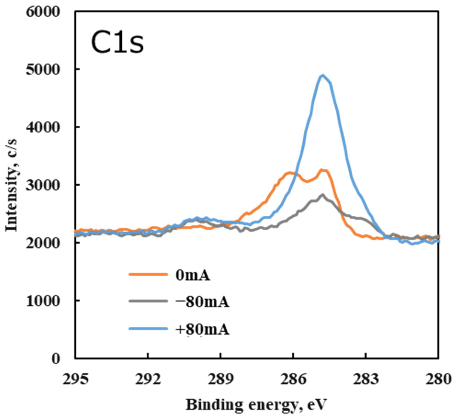
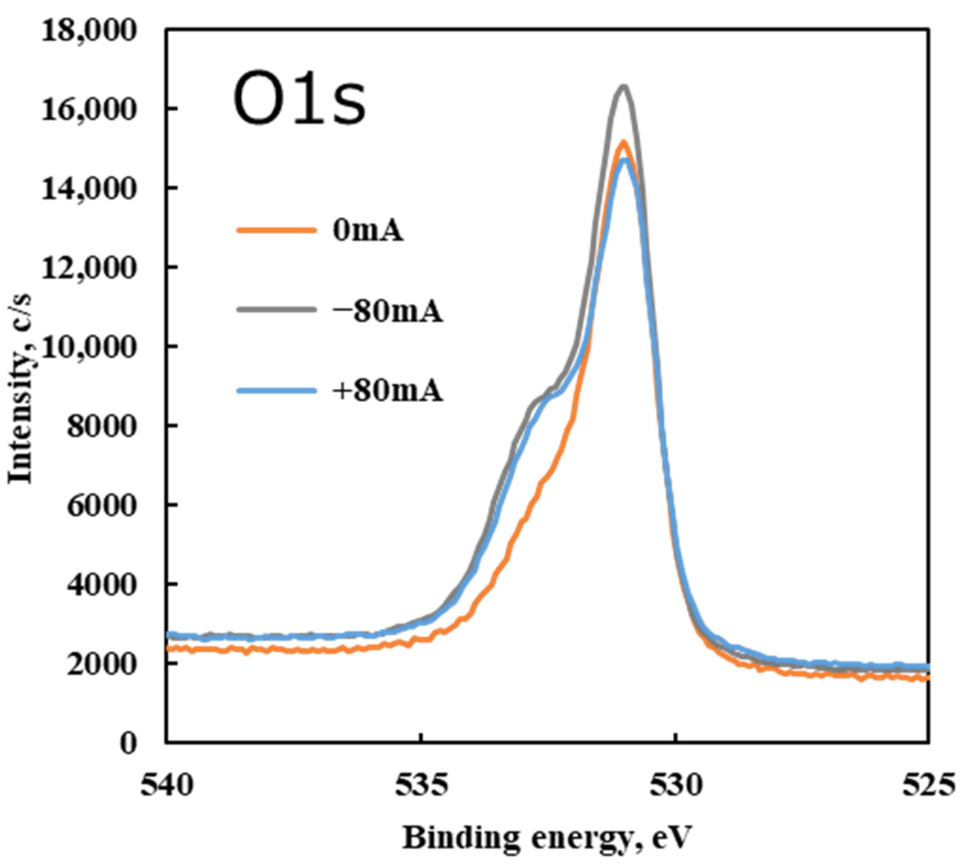
To further investigate the chemical states of the elements in the tribofilm, XPS was performed on the disk’s worn surface for different test conditions. Figure 14 shows the C 1s spectra and Figure 15 shows the O 1s spectra of the disk surface under non-electrified and electrified conditions.
In the C 1s spectrum, a primary peak was observed at approximately 284.5 eV under all conditions. This peak corresponds to carbon in C–C bonds, which is attributed to the hydrocarbon backbone of the lubricant and carbonaceous tribofilm. Under the non-electrified condition (0 mA), an additional C 1s peak appeared near 286 eV. The 286 eV component is associated with C–O bonds (ethers/alcohols). This indicates that some PPE lubricant residue (likely intact or partially decomposed molecules with ether linkages) remained adsorbed on the surface after the test without current. In other words, without an electrical current, a small amount of lubricant decomposition occurred due to friction, leaving behind species with C–O (ether) groups on the steel surface.
Under electrified conditions (+80 mA or −80 mA tests), the 286 eV C 1s peak (C–O) disappeared, and a new peak emerged around 290 eV in the C 1s spectrum. The 290 eV region corresponds to O=C–O (carboxyl) and related carbonate species [37]. The appearance of this 290 eV peak under electrical bias suggests that carbon from the PPE lubricant underwent further oxidation when a current was applied. Specifically, the applied electric current likely caused the cleavage of PPE’s ether bonds and facilitated the formation of highly oxidized carbon species (such as carboxylates or carbonates). These species are indicative of a higher oxidation state of carbon than the original lubricant molecules. In essence, friction plus current led to more oxidative reactions on the carbonaceous tribofilm. Moreover, under the ±80 mA conditions a subtle C 1s shoulder became evident at ~283 eV. This low binding energy signal is attributed to carbidic carbon (carbon bonded to metal, e.g., an iron carbide species) [37], implying that at a high current some decomposed carbon species bonded directly with the steel surface.
The O 1s spectra support this interpretation. Across all conditions, the O 1s spectra had their main peak at ~531 eV, which can be attributed to oxygen in metal oxides, primarily Fe–O (consistent with iron oxides like Fe2O3 identified by Raman). Under electrified conditions, a shoulder peak arose around 532.5 eV in the O 1s spectrum. Signals in the 532–533 eV range are generally associated with oxygen in hydroxides (OH) and in organic/inorganic carbonates [37]. The emergence of the 532.5 eV O 1s component with current indicates that oxidation reactions progressed further on the surface, producing hydroxide species and/or carbonate compounds. These could come from moisture traces (hydroxides) or from the oxidation of organic fragments of the lubricant (forming carboxylate/carbonate groups).
Collectively, the XPS findings suggest that the combination of frictional heating/mechanical action and the presence of an electric current greatly promotes the decomposition and oxidation of the PPE lubricant on the steel surface. The PPE’s ether bonds were cleaved, and the carbon in the tribofilm became bonded to oxygen in new functional groups (like carbonyl, carboxyl, hydroxyl). This observation is consistent with the Raman analysis, which indicated a tribofilm composed of carbon (from decomposed lubricant) and iron oxide. XPS adds that, under electrical conditions, those carbonaceous components are more oxidized (forming polar oxygen-containing species). These results reinforce the conclusion that electrical currents accelerate tribochemical reactions, resulting in a tribofilm that contains both carbonaceous material and oxidized compounds (including iron oxides and oxidized carbon fragments).

3.3. Discussion

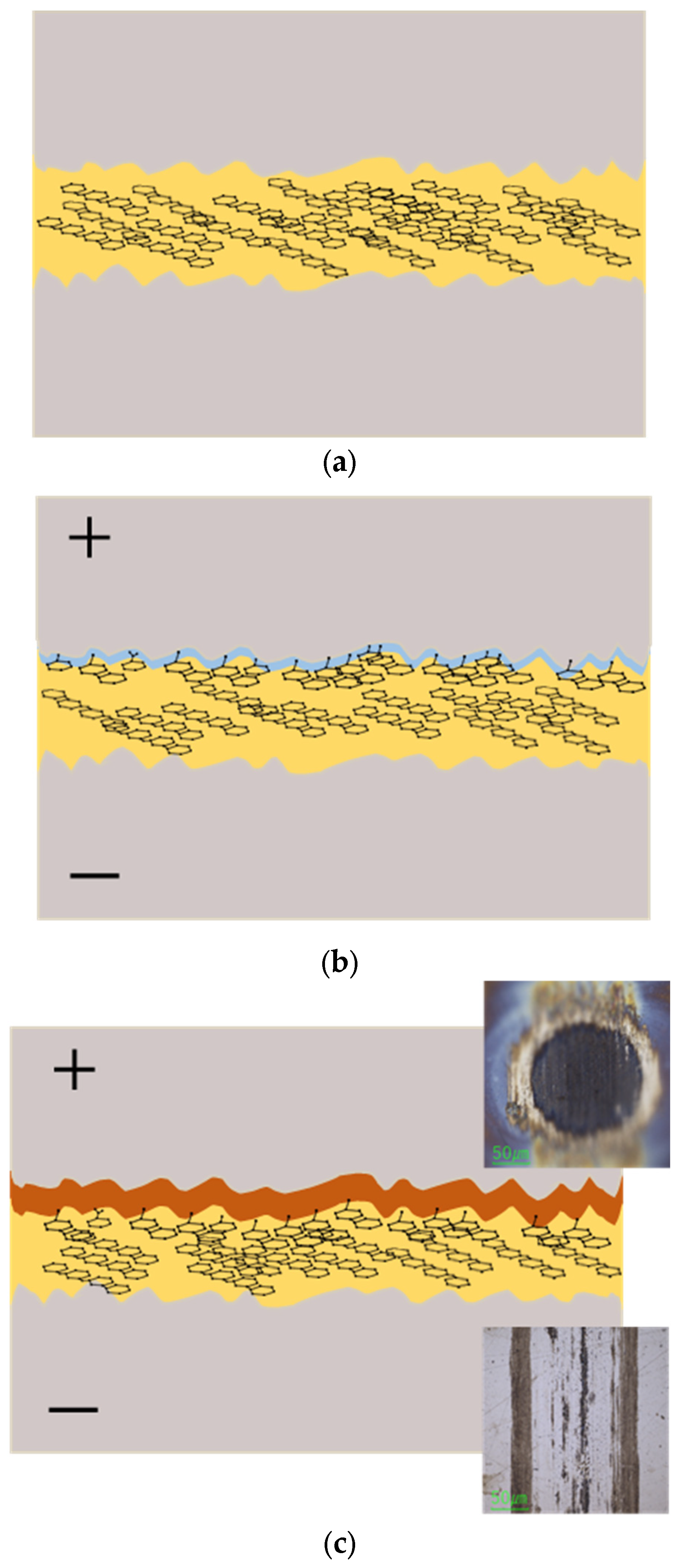
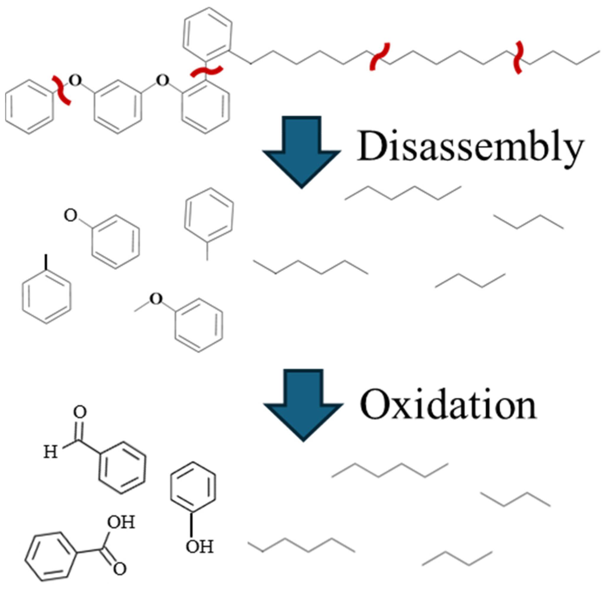
Based on the above results, we propose a mechanism for tribofilm formation in PPE-lubricated systems, illustrated schematically in Figure 16. Under non-electrified conditions, PPE molecules have a plate-like structure that allows them to adsorb parallel to the steel surface, forming a protective film that reduces friction (Figure 16a). This adsorption and alignment help minimize direct metal-to-metal contact. However, when friction generates nascent metal surfaces or significantly raises the local temperature, PPE molecules become more susceptible to decomposition (Figure 17). The breaking of molecular bonds (particularly the ether linkages) can occur due to the high surface energy of freshly exposed metal and the heat of friction.
In an electrified environment, these decomposition reactions are further accelerated by the presence of electrons and electric fields. The electrical current provides additional energy and can drive electrochemical reactions. Our XPS analysis revealed that an applied current leads to the cleavage of PPE’s ether bonds and the oxidation of the resulting fragments into polar functional groups (such as carbonyls and hydroxyls). Originally, PPE molecules are largely non-polar. Once decomposed and oxidized, they generate polar species.
These polar decomposition products are influenced by the electric field in the contact. They tend to migrate toward the positive electrode (the positively charged surface) under the field’s influence. Experimentally, we observed this effect: a thick carbonaceous deposit accumulated on the ball when the ball was the positive electrode, whereas almost no deposit formed on the ball when it was negative. This strongly supports the idea that the tribochemically generated products carry charge or dipoles that make them drift in the electric field, concentrating on the anode side (positive surface).
Through this process, a continuous supply of decomposition products (both carbonaceous fragments from the lubricant and iron oxide wear debris from the steel) is generated by ongoing friction. Simultaneously, the electric field drives these products onto the positive electrode surface and helps them adhere there. The tribofilm thus begins to form on the positive side. Initially, this tribofilm may be an ultrathin layer. As the test continues (and as long as current flows and friction generates more debris), the carbonaceous material and oxides accumulate, and the tribofilm grows progressively thicker (Figure 16b,c). In our experiments, after approximately 1 h of testing at +80 mA, a visibly thick tribofilm had developed on the positive (ball) surface.
A thin tribofilm is generally beneficial: it can fill in microscopic asperities and smooth the surface, thereby reducing friction. However, if the tribofilm grows too thick or extensive, it can become detrimental. An excessively thick tribofilm may be soft or abrasive and can increase effective contact area, disrupt the lubrication film, or break off in chunks—all of which can increase friction and wear. Indeed, we found that in the low-current range (up to ±10 mA), the tribofilm remained very thin and maintained the low-friction, low-wear benefits of PPE. In the high-current range (>10 mA), however, the tribofilm built up much more, which corresponded with a rise in friction and accelerated wear. Thus, there appears to be a threshold of electrical current (around 10 mA in our setup) below which tribofilm formation is mild and beneficial, and above which tribofilm accumulation becomes excessive and harmful to tribological performance.
Previous studies have reported that PPE lubricants can form polymeric films on surfaces during rubbing, which help reduce friction and also suppress hydrogen generation in steel [25]. The present study adds nuance to those findings by showing that the behavior of PPE’s tribofilm is strongly influenced by electrical current. We observed that the direction and magnitude of an applied current significantly affect the tribofilm’s growth and distribution (preferentially forming on the positive side). This is a notable new insight: tribofilms predominantly forming on the positively charged surface in an electric field is a phenomenon that needs to be considered in EV drivetrain applications. In summary, our proposed mechanism is that, under electrified conditions, PPE’s decomposition products, being polar, are drawn to the positive electrode, where they accumulate into a tribofilm. While a small amount of such film can be protective, too much leads to higher friction and wear. This understanding can guide the design of lubricants and additives for electrified systems to balance these effects.

4. Conclusions

In this study, the frictional behavior of a PPE-based lubricant under electrified conditions was evaluated using a reciprocating ball-on-disk test apparatus, with an emphasis on its low friction and superior wear resistance relative to a conventional PAO-based lubricant. The results demonstrated that, under PPE lubrication, the tribofilm’s adhesion characteristics varied significantly with the direction and magnitude of the applied current, whereas under PAO lubrication no significant changes were observed with current.
Furthermore, Raman, ToF-SIMS, and XPS analyses revealed that the tribofilm formed on the wear scars with PPE lubrication consisted of decomposition/oxidation products of PPE, with amorphous carbon identified as the primary component. This tribofilm preferentially formed on the positively charged surface, growing thicker when the ball specimen was at positive potential. The development of the tribofilm was accompanied by increases in friction and wear, becoming prominent at an applied current threshold of roughly 10 mA. Specifically, at currents of ±10 mA or below, the COF under PPE lubrication remained around 0.06–0.07, significantly lower than the ~0.10 observed with PAO. However, in the high-current region (>10 mA), the COF with PPE increased substantially; +20 mA resulted in approximately a 10% higher COF compared to the 0 mA condition and +80 mA caused roughly a 25% increase. In contrast, the PAO lubricant’s friction coefficient remained about 0.10 and showed almost no variation under all the tested conditions.
These findings indicate that, while PPE-based lubricants are more susceptible to electrical currents than PAO, they maintain excellent wear resistance and a low friction coefficient under moderate electrification (up to ±10 mA). Beyond this range, electrical effects lead to tribofilm over-growth which can negate the friction advantages. Therefore, PPE-based lubricants (such as R1-4P2E) are a promising candidate for use in electrified lubrication environments (e.g., EV drivetrains and other systems with electrical currents in contacts), provided that operating conditions are controlled to mitigate excessive tribofilm accumulation. This insight is valuable for the development of next-generation lubricants for electric vehicles, as it underlines the importance of considering electrical factors in tribological performance.

Author Contributions

Conceptualization, R.L.; methodology, C.W. and R.L.; validation, C.W. and R.L.; formal analysis, C.W. and R.L.; investigation, C.W., R.L., H.T., S.K., X.L. and P.C.; writing—original draft preparation, C.W. and R.L.; writing—review and editing, C.W. and R.L.; supervision, R.L.; project administration, X.L. and P.C.; funding acquisition, R.L., X.L. and P.C. All authors have read and agreed to the published version of the manuscript.

Funding

This research was partially funded by a Senior Visiting Scholarship from Fudan University, grant number 2024FGJ03.

Data Availability Statement

The data presented in this study are available upon request from the corresponding author.

Acknowledgments

The authors thank the MORESCO Corporation for supplying the lubricants.

Conflicts of Interest

The authors declare no conflicts of interest.

References

  1. Beyer, M.; Brown, G.; Gahagan, M.; Higuchi, T.; Hunt, G.; Huston, M.; Jayne, D.; McFadden, C.; Newcomb, T.; Patterson, S.; et al. Lubricant Concepts for Electrified Vehicle Transmissions and Axles. Tribol. Online 2019, 14, 428–437. [Google Scholar] [CrossRef]
  2. Matsumori, H. Electrical and Mechanical Technology from the Perspective of EV Drive System, e-Axle. J. Jpn. Soc. Appl. Electromagn. Mech. 2022, 30, 33–38. [Google Scholar] [CrossRef]
  3. Uemura, K. Development of Meiden’s e-Axle Traction Motor System. Meidensha Tech. Rev. 2021, 182, 28–33. [Google Scholar]
  4. Chen, S.T.; Lipo, T.A. Circulating type motor bearing current in inverter drives. IEEE Ind. Appl. Mag. 1998, 4, 32–38. [Google Scholar] [CrossRef]
  5. Plazenet, T.; Boileau, T.; Caironi, C.; Nahid-Mobarakeh, B. A comprehensive study on shaft voltages and bearing currents in rotating machines. IEEE Trans. Ind. Appl. 2018, 54, 3749–3759. [Google Scholar] [CrossRef]
  6. Willwerth, A.; Roman, M. Electrical Bearing Damage—A Lurking Problem in Inverter-Driven Traction Motors. In Proceedings of the 2013 IEEE Transportation Electrification Conference and Expo (ITEC), Detroit, MI, USA; 2013; pp. 1–5. [Google Scholar] [CrossRef]
  7. Romanenko, A.; Mütze, A.; Ahola, J. Effects of Electrostatic Discharges on Bearing Grease Electric Properties. In Proceedings of the 2015 IEEE International Electric Machines & Drives Conference (IEMDC), San Diego, CA, USA, 10–13 May 2015; pp. 1904–1910. [Google Scholar] [CrossRef]
  8. Romanenko, A.; Mütze, A.; Ahola, J. Effects of Electrostatic Discharges on Bearing Grease Dielectric Strength and Composition. IEEE Trans. Ind. Appl. 2016, 52, 4835–4842. [Google Scholar] [CrossRef]
  9. Stopher, M.A.; Rivera-Diaz-del-Castillo, P.E.J. Hydrogen Embrittlement in Bearing Steels. Mater. Sci. Technol. 2016, 32, 1184–1193. [Google Scholar] [CrossRef]
  10. Lu, R.; Minami, I.; Nanao, H.; Mori, S. Investigation of Decomposition of Hydrocarbon Oil on the Nascent Surface of Steel. Tribol. Lett. 2007, 27, 25–30. [Google Scholar] [CrossRef]
  11. Shimotomai, N.; Nanao, H.; Mori, S. Tribochemical Reaction of Benzene on Nascent Steel Surface and Effect of Temperature. Tribol. Online 2012, 7, 54–59. [Google Scholar] [CrossRef]
  12. Tanimoto, H.; Tanaka, H.; Sugimura, J. Observation of Hydrogen Permeation into Fresh Bearing Steel Surface by Thermal Desorption Spectroscopy. Tribol. Online 2011, 6, 291–296. [Google Scholar] [CrossRef]
  13. Nagumo, M. Hydrogen Related Failure of Steels—A New Aspect. Mater. Sci. Technol. 2004, 20, 940–950. [Google Scholar] [CrossRef]
  14. Kürten, D.; Khader, I.; Raga, R.; Casajús, P.; Winzer, N.; Kailer, A.; Spallek, R.; Scherge, M. Hydrogen Assisted Rolling Contact Fatigue Due to Lubricant Degradation and Formation of White Etching Areas. Eng. Fail. Anal. 2019, 99, 330–342. [Google Scholar] [CrossRef]
  15. Tanaka, H.; Ratoi, M.; Sugimura, J. The Role of Synthetic Oils in Controlling Hydrogen Permeation of Rolling/Sliding Contacts. RSC Adv. 2021, 11, 726–738. [Google Scholar] [CrossRef]
  16. Hope, K.J.L. PAO Contributions to Energy Efficiency in 0W-20 Passenger Car Engine Oils. Lubricants 2018, 6, 73. [Google Scholar] [CrossRef]
  17. Kwak, Y.; Cleveland, C.; Adhvaryu, A.; Fang, X.; Hurley, S.; Adachi, T. Understanding Base Oils and Lubricants for Electric Drivetrain Applications; SAE Technical Paper 2019-01-2337; SAE International: Warrendale, PA, USA, 2019. [Google Scholar] [CrossRef]
  18. Cai, W.; Wu, X.; Zhou, M.; Liang, Y.; Wang, Y. Review and Development of Electric Motor Systems and Electric Powertrains for New Energy Vehicles. Automot. Innov. 2021, 4, 3–22. [Google Scholar] [CrossRef]
  19. Esfahani, E.A.; Soltanahmadi, S.; Morina, A.; Han, B.; Nedelcu, I.; van Eijk, M.C.P.; Neville, A. The Multiple Roles of a Chemical Tribofilm in Hydrogen Uptake from Lubricated Rubbing Contacts. Tribol. Int. 2020, 146, 106023. [Google Scholar] [CrossRef]
  20. Kürten, D.; Khader, I.; Kailer, A. Tribochemical Degradation of Vacuum-Stable Lubricants: A Comparative Study between Multialkylated Cyclopentane and Perfluoropolyether in a Vacuum Ball-on-Disc and Full-Bearing Tests. Lubr. Sci. 2020, 32, 183–191. [Google Scholar] [CrossRef]
  21. Bhattacharya, S.; Resta, L.; Divan, D.M.; Novotny, D.W. Experimental Comparison of Motor Bearing currents with PWM hard- and soft-switched voltage-source inverters. IEEE Trans. Power Electron. 1999, 14, 552–562. [Google Scholar] [CrossRef]
  22. Muetze, A.; Binder, A. Techniques for Measurement of Parameters Related to Inverter-Induced Bearing Currents. IEEE Trans. Ind. Appl. 2007, 43, 1274–1283. [Google Scholar] [CrossRef]
  23. Xie, G.; Luo, J.; Guo, D.; Liu, S.; Li, G. Damages on the Lubricated Surfaces in Bearings under the Influence of Weak Electrical Currents. Sci. China Technol. Sci. 2013, 56, 2979–2987. [Google Scholar] [CrossRef]
  24. Gao, Z.; Salvi, L.; Flores-Torres, S. High Conductivity Lubricating Oils for Electric and Hybrid Vehicles. U.S. Patent 2018/0100115 A1, 12 April 2018. [Google Scholar]
  25. Lu, R.; Tani, H.; Koganezawa, S.; Hata, M. Alkylated Polyphenyl Ethers as High-Performance Synthetic Lubricants. Lubricants 2022, 10, 275. [Google Scholar] [CrossRef]
  26. Lee, P.M.; Uy, D.; Liang, H.; Null, V. Editorial: Fluids and Greases for Electrified Vehicles. Front. Mech. Eng. 2025, 11, 1569500. [Google Scholar] [CrossRef]
  27. Chen, Y.; Jha, S.; Raut, A.; Zhang, W.; Liang, H. Performance Characteristics of Lubricants in Electric and Hybrid Vehicles: A Review of Current and Future Needs. Front. Mech. Eng. 2020, 6, 571464. [Google Scholar] [CrossRef]
  28. Minami, I. Ionic Liquids in Tribology. Molecules 2009, 14, 2286–2305. [Google Scholar] [CrossRef]
  29. Bair, S.; Liu, Y.; Wang, Q.J. The Pressure-Viscosity Coefficient for Newtonian EHL Film Thickness with General Piezoviscous Response. J. Tribol. 2006, 128, 624–631. [Google Scholar] [CrossRef]
  30. Ferrari, M.; Zenoni, A.; Lee, Y.; Hayashi, Y. Characterization of a Polyphenyl Ether Oil Irradiated at High Doses in a TRIGA Mark II Nuclear Reactor. Nucl. Instrum. Methods Phys. Res. Sect. B Beam Interact. Mater. At. 2021, 497, 1–9. [Google Scholar] [CrossRef]
  31. Galmiche, B.; Ponjavic, A.; Wong, J.S.S. Flow Measurements of a Polyphenyl Ether Oil in an Elastohydrodynamic Contact. J. Phys. Condens. Matter 2016, 28, 134005. [Google Scholar] [CrossRef] [PubMed]
  32. Hata, M.; Maeda, T.; Hayashi, M. Structure and Properties of Phenylether Lubricants. J. Jpn. Soc. Tribol. 2020, 65, 165. [Google Scholar] [CrossRef]
  33. Mirzaei, A.; Janghorban, K.; Hashemi, B.; Hosseini, S.R.; Bonyani, M.; Leonardi, S.G.; Bonavita, A.; Neri, G. Synthesis and Characterization of Mesoporous α-Fe2O3 Nanoparticles and Investigation of Electrical Properties of Fabricated Thick Films. Process. Appl. Ceram. 2016, 10, 209–217. [Google Scholar] [CrossRef]
  34. Pathak, D.K.; Thakur, D.O.P.; Kumar, R. Raman Area- and Thermal- Mapping Studies of Faceted Nano-crystalline α-Fe2O3 Thin Films Deposited by Spray Pyrolysis. Can. J. Chem. 2022, 100, 507–511. [Google Scholar] [CrossRef]
  35. Sheng, H.; Xiong, W.; Zheng, S.; Chen, C.; He, S.; Cheng, Q. Evaluation of the sp3/sp2 ratio of DLC films by RFPECVD and its quantitative relationship with optical band gap. Carbon Lett. 2021, 31, 929–939. [Google Scholar] [CrossRef]
  36. Song, H.; Casey, A.; Tory, J.; Rogers, N.J.; Coultas, D. Biodiesel Promotes Iron-Catalyzed Oxidation of Engine Lubricating Oil. Ind. Eng. Chem. Res. 2023, 62, 8711–8720. [Google Scholar] [CrossRef]
  37. Moulder, J.F.; Stickle, W.F.; Sobol, P.E.; Bomben, K.D. Handbook of X-Ray Photoelectron Spectroscopy; Physical Electronics USA, Inc.: Chanhassen, MN, USA, 1995. [Google Scholar]
Figure 1. Chemical structure of lubricants. (a) PAO (b) R1-4P2E.
Lubricants 13 00173 g001
Figure 2. (a) Photograph of reciprocating friction tester and (b) schematic diagram.
Lubricants 13 00173 g002
Figure 3. Effect of applied electric current on coefficient of friction.
Lubricants 13 00173 g003
Figure 4. Wear scars on ball (PAO, −80 mA to +80 mA).
Lubricants 13 00173 g004aLubricants 13 00173 g004bLubricants 13 00173 g004c
Figure 5. Wear scars on disk (PAO, −80 mA to +80 mA).
Lubricants 13 00173 g005aLubricants 13 00173 g005bLubricants 13 00173 g005c
Figure 6. Wear scars on ball (R1-4P2E, −80 mA to +80 mA).
Lubricants 13 00173 g006aLubricants 13 00173 g006bLubricants 13 00173 g006c
Figure 7. Wear scars on disk (R1-4P2E, −80 mA to +80 mA).
Lubricants 13 00173 g007aLubricants 13 00173 g007bLubricants 13 00173 g007c
Figure 8. Effect of applied current on wear scar size (ball wear scar diameter).
Lubricants 13 00173 g008
Figure 9. Raman spectrum of R1-4P2E.
Lubricants 13 00173 g009
Figure 10. Raman spectra of wear scars on ball.
Lubricants 13 00173 g010
Figure 11. Raman spectra of wear scars on disk.
Lubricants 13 00173 g011
Figure 12. Normalized intensity of graphitic carbon fragments (IC6n) in tribofilm.
Lubricants 13 00173 g012
Figure 13. Normalized intensity of hydrocarbon fragments (ICnH2n+1) in tribofilm.
Lubricants 13 00173 g013
Figure 14. XPS analysis of wear scars on disk (C1s).
Lubricants 13 00173 g014
Figure 15. XPS analysis of wear scars on disk (O1s).
Lubricants 13 00173 g015
Figure 16. Proposed model of tribofilm formation mechanism under electrical current: (a) initial state with no film; (b) thin tribofilm forming at positive surface; (c) thick tribofilm accumulating at positive surface over time.
Lubricants 13 00173 g016
Figure 17. Schematic illustration of R1-4P2E decomposition and oxidation processes.
Lubricants 13 00173 g017
Table 1. Physical properties of lubricants evaluated in this work.
ProductPAOR1-4P2E
Density (g/cm3)0.8261.014
Viscosity
(40 °C, mm2/s)
30.5240
Viscosity index13532
Flash point (°C)238308
Pour point (°C)−65−15
Disclaimer/Publisher’s Note: The statements, opinions and data contained in all publications are solely those of the individual author(s) and contributor(s) and not of MDPI and/or the editor(s). MDPI and/or the editor(s) disclaim responsibility for any injury to people or property resulting from any ideas, methods, instructions or products referred to in the content.