Abstract
The lubrication behavior and mechanical characteristics of the main bearing area of an aero-engine main shaft bearing determine the reliability and life of the main shaft bearing. In aero-engine main shaft bearings, the lubricant not only plays the role of lubrication but also affects the dynamic characteristics of the bearing; therefore, if the lubricant drag force is insufficient, it will lead to rolling body slipping. Slipping not only affects the reliability of the bearing operation but also will make the temperature of the contact area instantaneously increase, leading to the occurrence of gluing, scraping and other lubrication failure phenomena in the main bearing area. A lubricant under the shear conditions of traction characteristics is actually the external manifestation of rheological properties. Rheological properties are one of the elastic fluid power lubrication theories and are an important part of the study. Elasto-hydrodynamic lubrication theory of the oil film pressure, film thickness and temperature and solid domains interact to form a thermal–fluid–solid coupling relationship; this coupling relationship affects the main bearing area of the lubrication behavior and mechanical properties, thus affecting the lubrication state of the bearings and dynamic characteristics. With the continuous improvement of aero-engine performance requirements for main shaft bearings, it is of great significance to carry out a coupling study of the lubrication behavior and mechanical properties of the bearing contact zone under heavy load, high speed and high temperature conditions to improve the service performance, reliability and life of the bearings.
1. Introduction
Under high-speed and heavy-load conditions, an aero-engine’s main shaft roller bearings may tilt and skew, which will change the lubrication state of the main contact area and the stress–strain of the raceway, and then lead to lubrication failures such as gluing and scratching on the surface of the raceway. If the roller tilts or skews greatly, it may also lead to a violent collision between the roller and the cage, which will affect the reliability and life of the roller bearing [1,2]. Thus, it is necessary to study the lubrication state and stress–strain of the contact area when the roller tilts and skews.
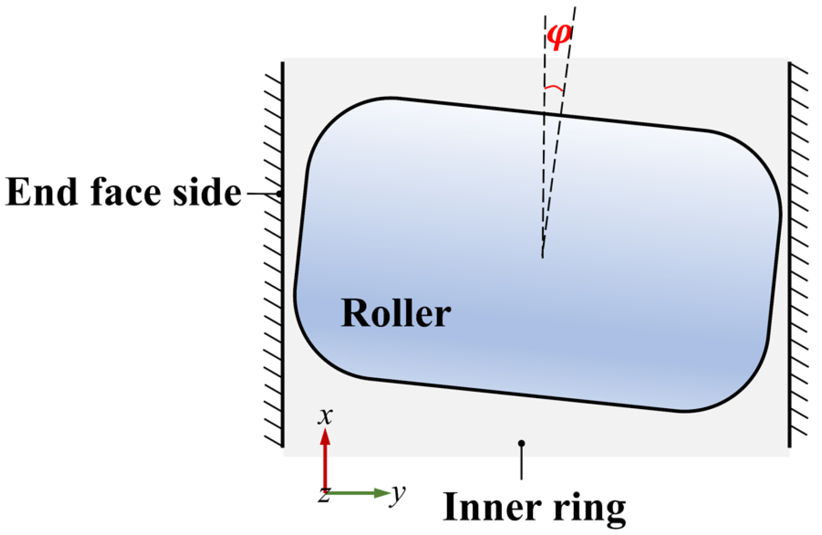
Previous pieces of literature have studied the influence of a roller’s tilt and skew on oil film pressure and oil film thickness based on the finite difference method (FDM); however, most of them only focus on the film thickness, pressure and temperature in elasto-hydrodynamic lubrication (EHL), and most do not consider the fluid–structure interaction of the EHL with the contact surface. Qiu et al. established a finite line contact EHL model of the roller bearings based on FDM and the Finite Element Method (FEM) and studied the effect of the roller’s tilt on the oil film thickness and oil film pressure [3]. Chen et al. established the lubrication model of finite line contact roller bearings and studied the influence of entrainment speed on EHL [4]. Based on FDM, Xu et al. and Ma et al. established a finite length roller EHL model of roller bearings and obtained the EHL numerical solutions of different roller shapes [5,6]. Sun et al. studied the EHL characteristics of Lundberg logarithmic roller bearings and crown rollers based on FDM and the multi-grid integration method [7,8]. Based on the finite-length elastic space theory, Luo used the composite iterative method to solve the oil film pressure and the fast Fourier transform to solve the elastic deformation to establish the finite-length roller line contact thermal EHL model [9]. Based on FDM, Bai and Huang used the multi-grid method to study the effects of the roller’s tilt and skew on the oil film pressure, oil film thickness and temperature, respectively [10,11]. Wu et al. studied the influence of geometric modification on the mixed lubrication of cylindrical roller bearings based on FDM and FEM. Although a few references combine the finite-length contact EHL with the stress–strain in the elastic mechanics, FDM and FEM are used separately in them, and the results of the two numerical methods iteratively study EHL and the stress–strain of the substrate [2,12]. Figure 1 is a schematic diagram of a roller bearing and its main bearing area.
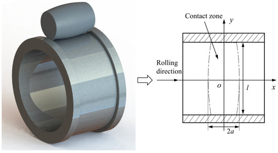
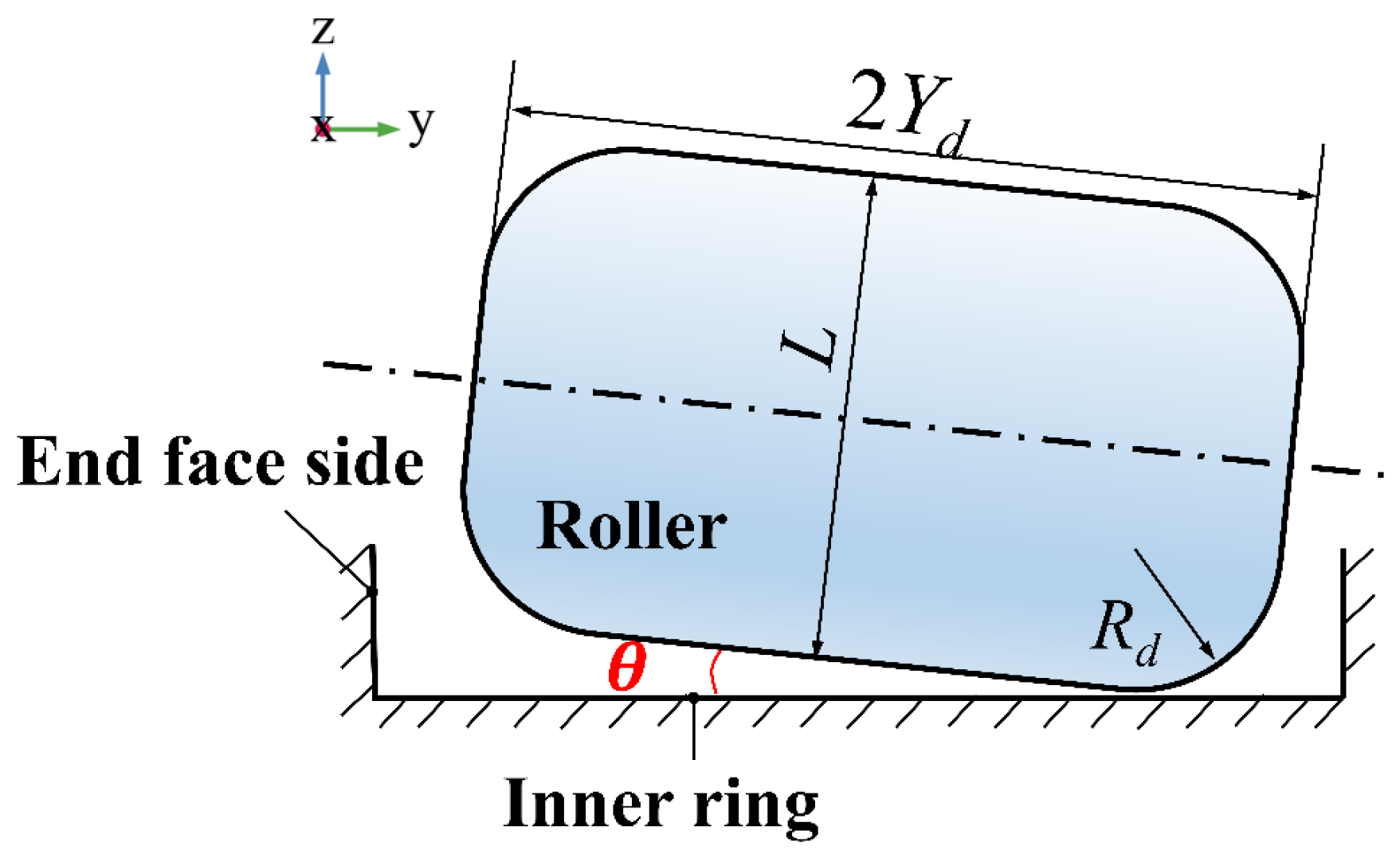
Figure 1.
Geometry of finite line contact of the roller bearings.
The finite element Full-system approach of EHL can not only study the oil film thickness, pressure and temperature in the EHL of point/line contact but also obtain the solid stress–strain and temperature in the contact area at the same time. It not only solves the problem of the low convergence rate of EHL under heavy load conditions but also expands the research scope of EHL. Based on the finite element Full-system approach, Hultqvist et al. established the transient EHL solution model of three-dimensional finite linear contact of roller bearings [13]. Habchi established an EHL model of finite-length three-dimensional linear contact roller bearings based on the finite element Full-system approach and studied the effect of roller morphology on oil film thickness, oil film pressure and oil film temperature [14,15]. Mounayer and Habchi used static reduction to reduce the size of the linear elastic part of the whole matrix system based on the Full-system approach and used the splitting algorithm to avoid the burden of solving the semi-dense matrix system. The results revealed the accuracy of the proposed method [16]. Schmid et al. studied the scale effect of the gear contact radius on film thickness, temperature rise and friction based on the Full-system approach [17]. Higashitani et al. optimized the calculation area of the elasto-hydrodynamic lubrication inlet so that accurate oil film thickness and oil film pressure can still be obtained under the condition of inlet length change [18].
The Full-system approach has been demonstrated to be a more efficient solution than the traditional relaxation iteration method in solving the elastic deformation equation, the hydrodynamic lubrication equation and the load balance equation. In comparison with the traditional relaxation iteration method, the Full-system approach has the capacity to update all variables concurrently within a single iteration process, thereby circumventing the oscillation problem that arises from repeated iterations in the semi-coupled method. This not only reduces the calculation time but also improves the stability of the numerical solution. In conditions of high load, high speed or when considering the characteristics of non-Newtonian fluid, the thickness of the lubricating film changes drastically and the pressure gradient is large. The Full-system approach was shown to offer a more stable solution to these complex problems and to circumvent the issues of non-convergence and reduced solution accuracy that are often associated with traditional methods due to nonlinear enhancement.
Based on the finite element Full-system approach, there are few reports on the influence of the roller’s tilt and skew on the lubrication state and stress–strain of the contact area. Therefore, based on the finite element Full-system approach, this paper establishes a fluid–structure interaction model of three-dimensional finite line contact EHL of the roller bearings. The effects of the roller’s tilt and skew on the lubrication state and stress–strain of the contact area are studied under the working conditions of aero-engine main shaft bearings. This provides a theoretical basis for the subsequent study about the effect of subsurface inclusions on the lubrication condition and fatigue life when the roller tilts and skews.
2. Materials and Methods
In this section, oriented to the high-speed and heavy-load working conditions of aero-engine main shaft bearings, a research model of EHL and stress–strain coupling in the main bearing zone of three-dimensional finite-length linear contact roller bearings is established to study the effects of roller deflection and skewing on the lubrication state of the contact zone and the rings subjected to stress–strain. Firstly, the theoretical equations of Full-system approach of infinite-length elastic half-space theory are corrected, and a three-dimensional finite-length line contact roller bearing elasto-fluid lubrication model is established; secondly, the influence of heavy-loaded and high-speed working conditions on the lubrication of the roller bearings is investigated for the working conditions of aero-engine main shaft bearings; thirdly, the influences of radial deflection and tangential skewing of the roller on the lubrication status and stress–strain are investigated; lastly, the effect of roller morphology on the lubrication state and stress–strain is studied to provide more theoretical basis for analyzing the lubrication state of roller bearings and the design of roller bearings.
In this paper, firstly, the coupling analysis model based on Full-system approach is modified, and a three-dimensional finite-length linear contact roller bearing lubrication behavior and stress–strain coupling analysis model is established; secondly, the lubrication research needs of roller bearings under heavy load conditions are met by introducing artificial convection steady state term in Reynolds equation; finally, the oil film thickness equation is modified, and the roller’s influence on the lubrication state and stress–strain in the radial deflection and tangential skew as well as roller morphology are investigated. Finally, the oil film thickness equation is modified to study the effect of roller in radial skew and tangential skew as well as roller morphology on the lubrication state and stress–strain.
The Reynolds equation, load balance equation, lubricating oil viscosity–pressure equation and lubricating oil density–pressure equation in the finite element Full-system approach are consistent with EHL numerical method of the finite difference method. However, the Boussinesq equation is no longer used to solve the elastic deformation in the oil film thickness equation. Instead, based on the generalized Hooke’s law, the fluid domain and the solid domain are coupled by taking the oil film pressure and the load of the elastic body as the medium to solve the stress and strain of the elastic body, and then the surface deformation of the elastic body is obtained, thereby obtaining the oil film thickness. The relationship between stress and strain in generalized Hooke’s law is expressed using elastic modulus and Poisson’s ratio as follows [19]:
where , , .
In the above expressions, i represents the direction of the component and j represents the direction of elastic deformation, so , let:
Expression (1) can be rewritten as:
In the fluid–structure interaction EHL model of roller bearings with finite length three-dimensional line contact, the above expression should be written as shown in Equation (3).
where , bH is the width of Hertz contact radius, L is the length of roller.
The dimensionless form of Reynolds equation is shown in Equation (4):
where .
—Entrainment speed, m/s;
—Lubricating oil viscosity, Pa·s;
—Lubricating oil density, kg/m3;
—Oil film thickness, m;
P—Dimensionless contact pressure acting on the boundary ;
—Test function used in FEM solving process;
—Coefficient of penalty term [20];
H—Dimensionless oil film thickness;
X—Dimensionless x coordinate on the boundary .
In this work, only the above weak form is used to solve the Reynolds equation, and the maximum Hertz contact stress can be only less than 0.5 GPa, with low convergence rate. Therefore, the artificial diffusion term is introduced in references [21,22,23].
Different from two-dimensional line contact and three-dimensional point contact, the oil film equation needs to be modified in the three-dimensional finite line contact EHL model, as shown in Equation (5) [14].
Compared with the film thickness equation of two-dimensional infinite line contact and three-dimensional point contact, Equation (5) has an additional term , which is a correction term for the shape of both end faces of the roller.
There are various expressions for the end morphology of roller bearings [24]:
- (1)
- Lundberg rollers (Lundberg profile)
An alternative mathematical expression for the roller morphology in dimensionless form is given in the literature [14] as
where the expression for Rd is
As shown in Figure 2, when K2 < 1, the roller morphology is a linear busbar roller; when K2 = 1, the roller morphology is a circular logarithmic busbar roller. Therefore, the value of K2 and the radius of curvature of the roller chamfer Rd as well as the edge length zm on both sides of the roller determine the roller morphology.
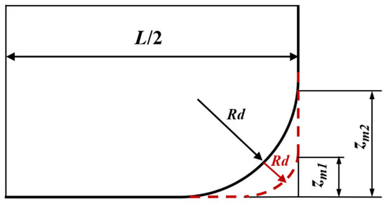
Figure 2.
The diagram of roller profile.
- (2)
- Straight rollers
- (3)
- Circular arc logarithmic busbar roller
When the roller tilts in the radial direction, as shown in Figure 3, the film thickness equation is written in Equation (15) [12]:
where .
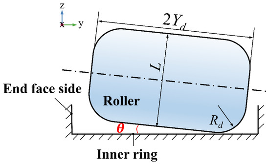
Figure 3.
Schematic diagram of roller’s tilt.
When the roller skews in the tangential direction, as shown in Figure 4, the film thickness equation can be written as Equation (16) [10]:

Figure 4.
Schematic diagram of roller’s skew (Top view).
Other equations used in this paper: WLF equation of viscosity–pressure equation of lubricating oil is Equation (17) and the parameters are in Table 1.

Table 1.
Parameters of WLF equation [13].
The density–pressure equation of lubricating oil is Dowson–Higginson equation [24]:
Load balance equation:
Hertz contact radius width bH and Maximum Hertz contact stress ph:
where F is the external load, and E′ is the equivalent elastic modulus. Table 2 shows the roller geometry and material parameters.
Table 2.
Roller geometry and material parameters and the coefficient in the term.
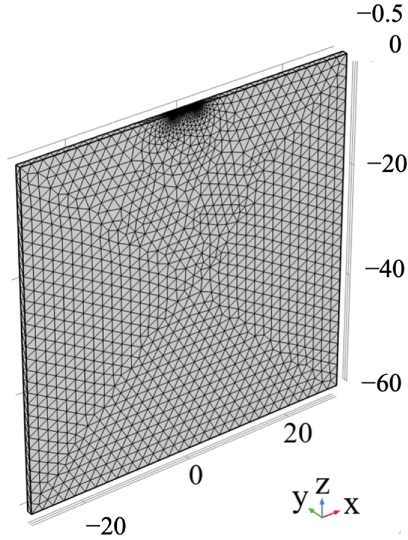
Here, the dimensionless form is used for modeling and solving, in the geometry module in COMSOL Multiphysics 5.4, a solid domain of 60 (length) × 60 (height) × 1 (depth) is created with coordinates −30 ≤ X ≤ 30, −1 ≤ Y ≤ 0, −60 ≤ Z ≤ 0. A region of −3 ≤ X ≤ 1.5 is defined to be divided in the x–y plane at z = 0, which is defined as the contact surface, as shown in Figure 5. In order to ensure the accuracy of the calculation results, the contact area in the solid domain is extended downward by a distance of 3 units, and a cubic subdomain is divided for mesh encryption. The 60, 30 and 15 discrete points are set in the x, y and z directions, respectively, which are mapped to the opposite edge local encryption using the mapping conditions in the mesh module, and the mesh in the model has a total of 52,362 units.
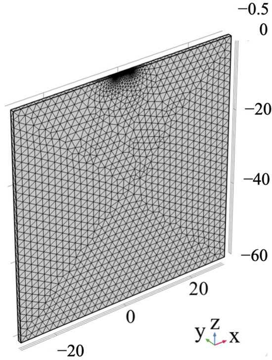
Figure 5.
Geometric model and mesh generation of 3D finite line contact roller bearing.
In the structural mechanics module, define the x–z section with y = 0 as a symmetric boundary condition, the bottom surface is defined as a fixed constraint, the contact zone is defined as the pressure p of the oil film, and the other parameters are kept as default. The weak form of the Reynolds equation with a steady state term given above is entered in the Partial Differentiation in Weak Form module, and the definition of the initial values can be found in the literature [25]. The solver setup is the same as in the 2D line contact and 3D point contact models in the previous chapter. The MUMPS (Multifrontal Massively Parallel Direct Solver) in the COMSOL Multiphysics 5.4 is selected as the solver, and the Newton–Raphson solution method is used. The convergence residual is defined as 0.001, and the number of iterations reaches 1000 steps to terminate the calculation.
On a desktop computer with a CPU of Intel(R) Core(TM) i5-6500, CPU 3.2 GHz, RAM of 16 GB, and a graphics card of Intel(R) HD Graphics 530 (Intel, Santa Clara, CA, USA), the computation takes 52 min 35 s under the working conditions of a maximum Hertz contact stress of 1.7 GPa, and a coiling suction speed of 0.5 m/s.
3. Results and Discussion
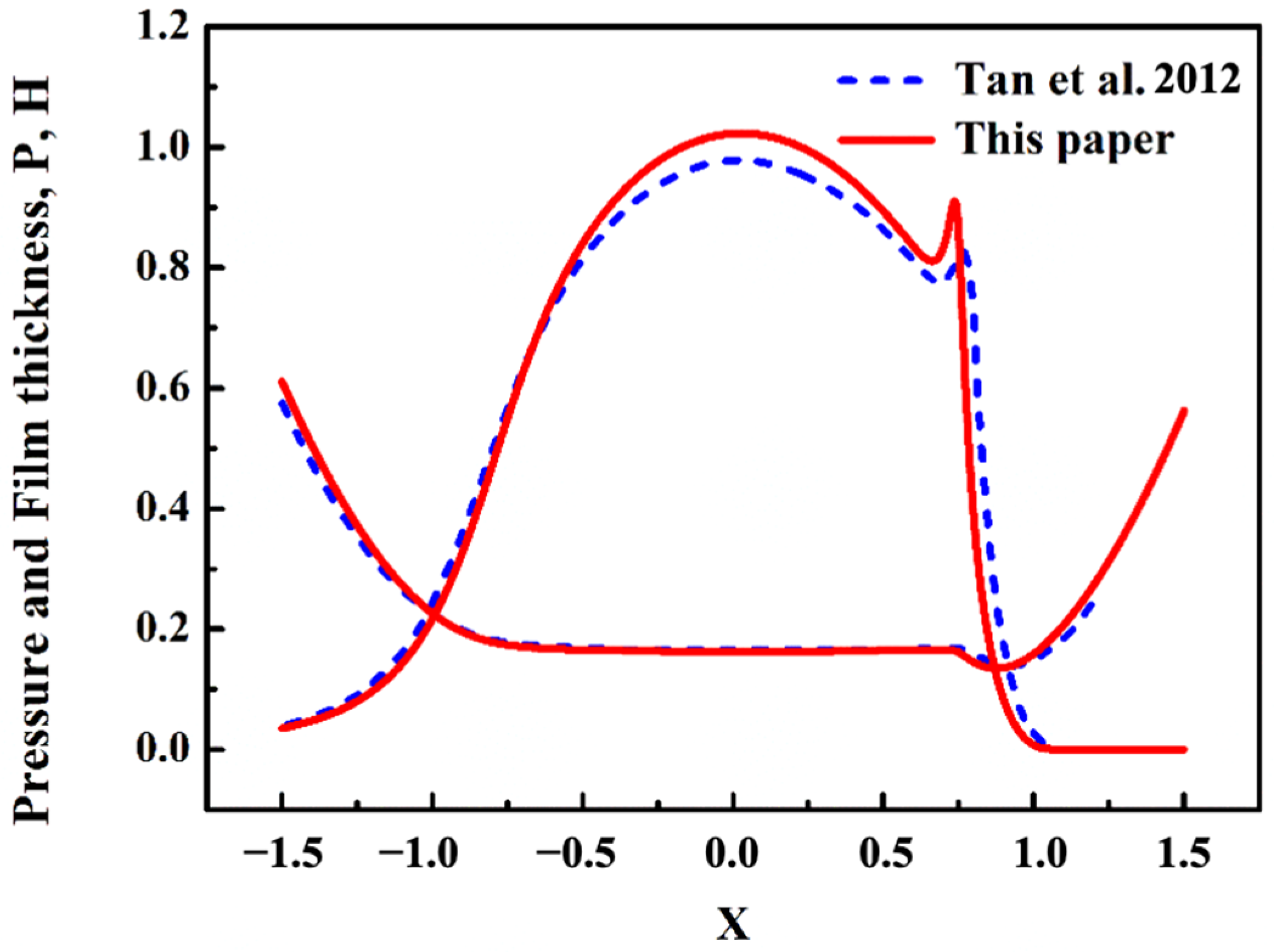
To verify the correctness of solving EHL with a multi-physical field model, the oil film thickness and oil film pressure were calculated under the working conditions of a load of 0.37 GPa and an entrainment speed of 0.2 m/s. The solution of oil film thickness and oil film pressure calculated by the line contact coupling model in this paper is the same as that in reference [26]. The same solution shows that the model established in this paper is correct (see Figure 6).
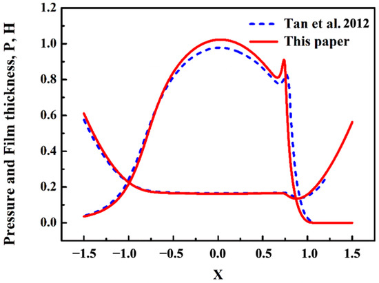
Figure 6.
Comparison of results between this paper and reference [26].
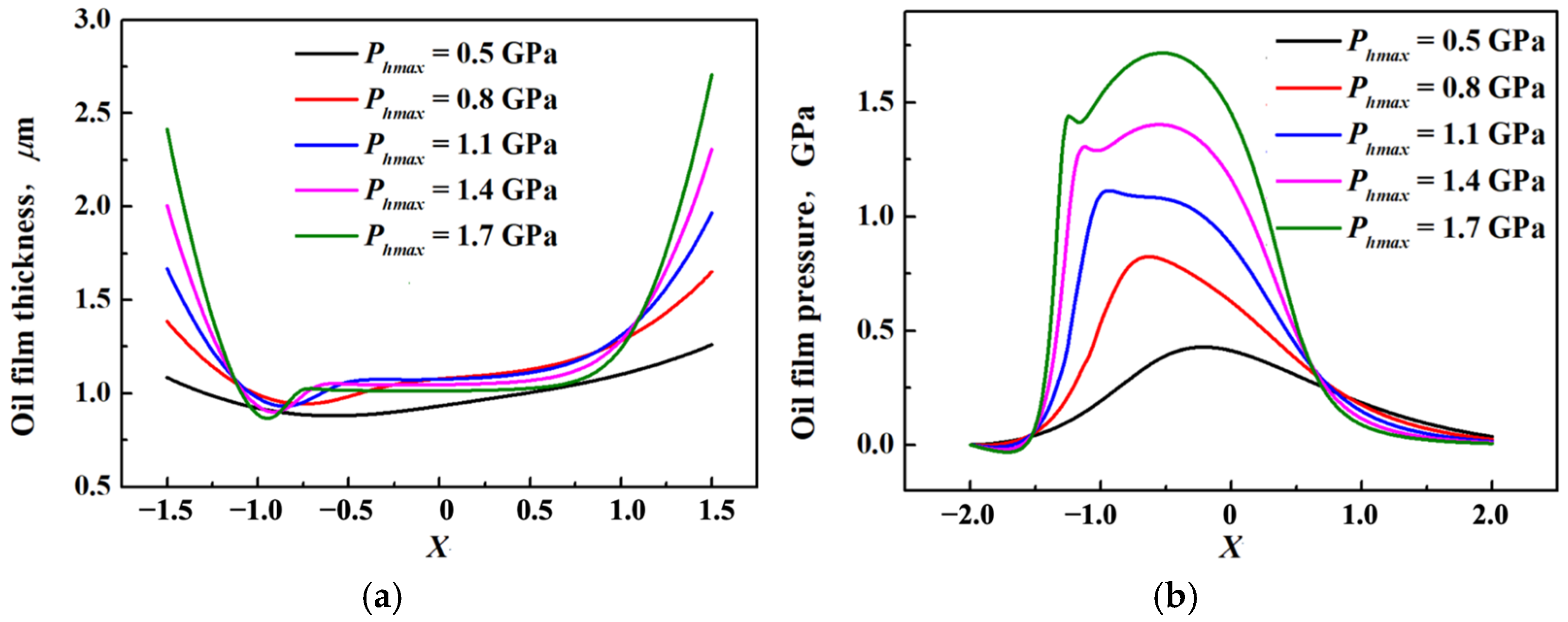
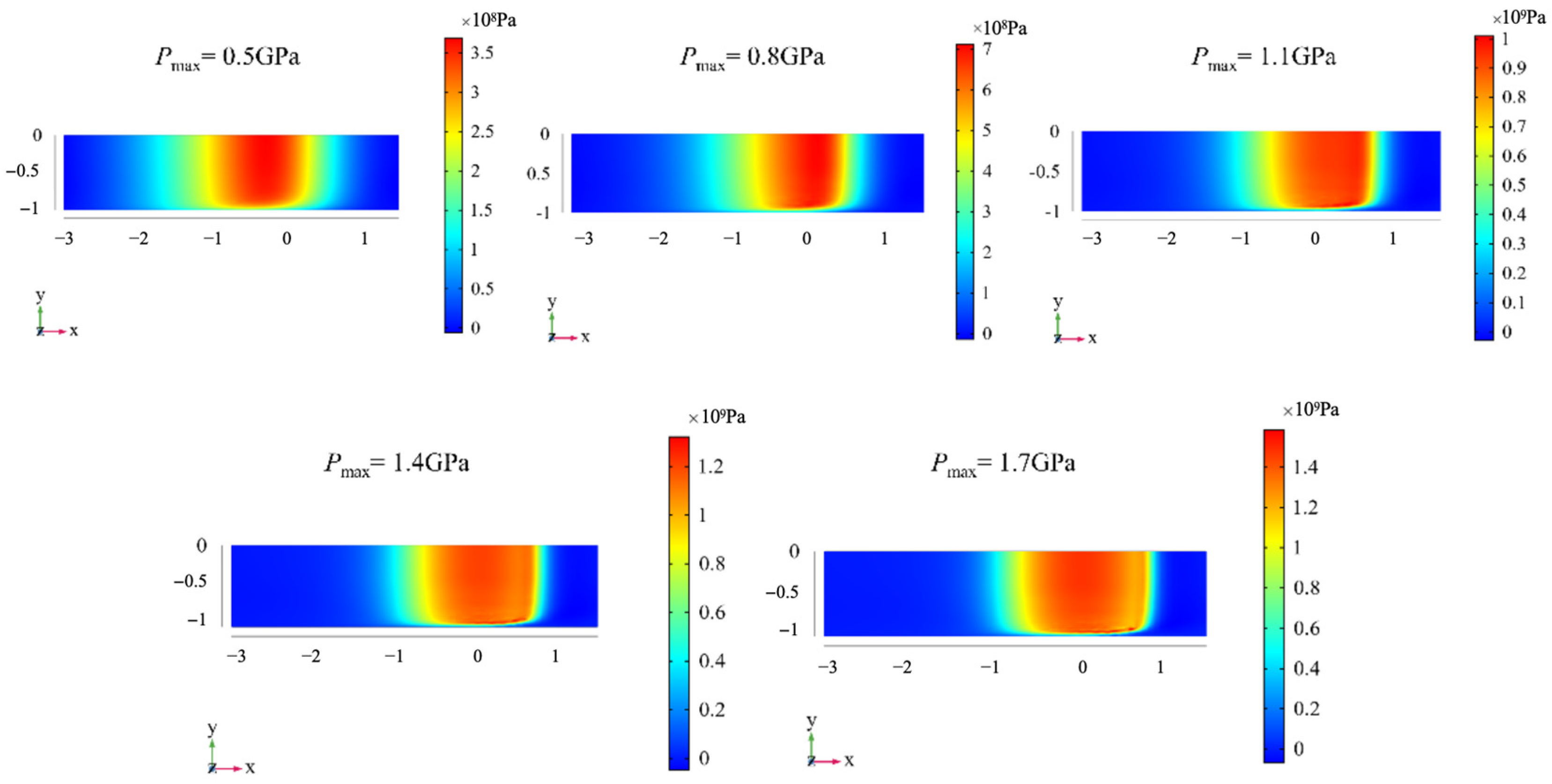
In the case of constant roll suction speed, the effects of different loads on the lubrication state and mechanical properties of the middle and end of the roller are investigated. The entrainment velocity is set to 0.5 m/s, and the effect of load increasing from 0.5 GPa to 1.7 GPa on the lubrication state and stress of the contact area is studied. Figure 7 shows the oil film thickness and pressure in the middle of the roller under different loads. With the increase in load, the necking of elastic hydrodynamic lubrication oil film becomes more and more obvious, and the necking position moves backward. The pressure of the oil film increases gradually, and the secondary pressure peak is more and more obvious. From the three-dimensional view of oil film pressure, with the increase in load, the oil film pressure of the end face is increasing, and the stress on the raceway surface is also increasing.
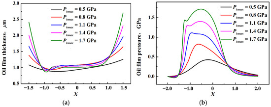
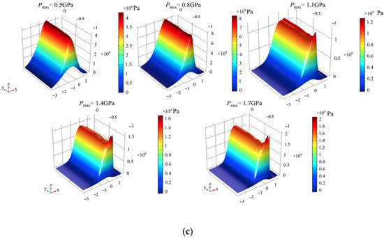
Figure 7.
Oil film pressure and oil film thickness under different loads: (a) oil film thickness in the contact area; (b) oil film pressure in the contact area; (c) 3D oil film pressure in the contact area.
Figure 8 shows that the stress on the raceway surface is smaller than the oil film pressure. With the increase in load, the width of the Hertz contact radius increases, and the stress concentration at the end of the ring becomes more and more obvious.

Figure 8.
Normal stress on the surface in the top view under different loads.
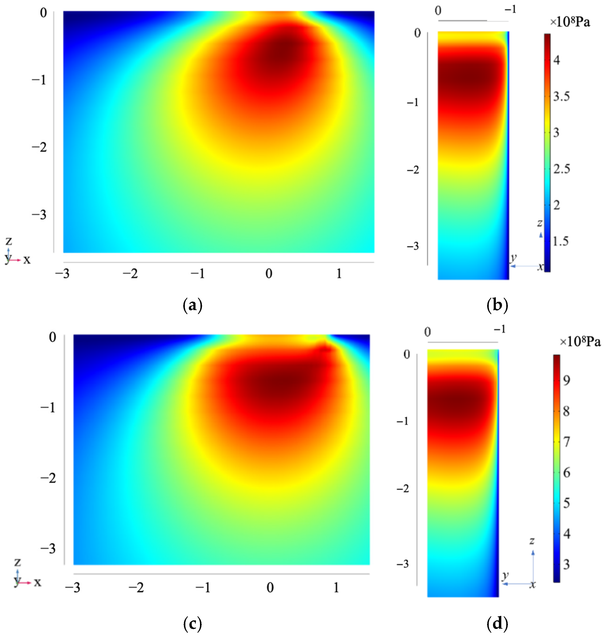
Taking the maximum Hertz contact stress of 0.8 GPa and 1.7 GPa as examples, the von Mises stress inside the raceway is given, as shown in Figure 9. Figure 9a,c show the view of the roller end face, the x–z direction view, and Figure 9b,d show the view of the roller motion direction, the y–z direction view. Although the loads are different, the von Mises stress distribution is almost the same, and the maximum stress is about 0.7 times the Hertz contact half-width below the surface.
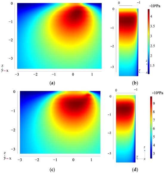
Figure 9.
The von Mises stress of the raceway in x–z and y–z views under different loads: (a) von Mises stress of raceway in x–z view with the max Hertzian pressure 0.8 GPa; (b) von Mises stress of raceway in y–z view with the max Hertzian pressure 0.8 GPa; (c) von Mises stress of raceway in x–z view with the max Hertzian pressure 1.7 GPa; (d) von Mises stress of raceway in y–z view with the max Hertzian pressure 1.7 GPa.
Under the condition of constant load of 1.7 GPa, the suction speed was gradually increased from 0.5 m/s to 2.5 m/s to study the effect of changing suction speed on the lubrication status and mechanical properties of the collar. Figure 10 shows the size and distribution of the oil film in the contact area under different suction speeds. As can be seen from the figure, in the x–x cross-section direction, it is observed that with the increase in the coiling suction speed, the oil film thickness gradually increases from about 1 μm to about 3 μm, and all of them form a necking at the same position down-stream, and the minimum oil film thickness is slightly smaller than the center oil film thickness. The secondary pressure peak of the oil film also increases gradually, but the coiling speed does not affect the primary pressure of the oil film. From the three-dimensional pressure distribution of the oil film, it can also be observed that the secondary pressure peak of the oil film becomes stronger and stronger with the increase in the coiling and suction speed, but the coiling and suction speed does not affect the size of the pressure of the oil film at the end, and the pressure of the oil film at the end is gradually concentrated to one place with the increase in the coiling and suction speed.
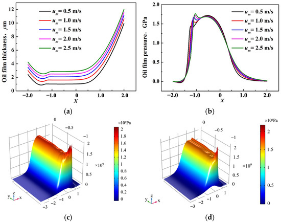
Figure 10.
Distribution of oil film in contact area under different entrainment speeds: (a) thickness of the oil film in the contact area within the x–x section in the middle of the roller; (b) oil film pressure in the contact area within the x–x section in the middle of the roller; (c) um = 0.5 m/s; (d) um = 2.5 m/s.
3.1. The Effects of the Roller’s Tilt on the Fluid–Structure Interaction of EHL
Under the working conditions of the maximum Hertz contact stress of 1.5 GPa and the entrainment speed of 1 m/s, the roller tilts 0.04° and 0.06°, the influence of the roller’s tilt on the lubrication state and stress–strain of the contact area is studied. Figure 11 shows the oil film pressure and thickness in the middle of the roller. The roller’s tilt hardly changes the oil film pressure and thickness.
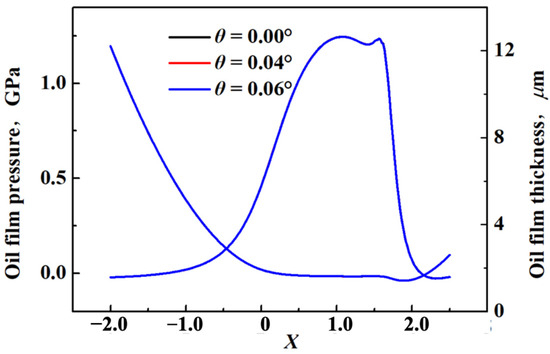
Figure 11.
Oil film thickness and oil film pressure in the middle of the roller when the roller tilts.
Table 3 shows the minimum oil film thickness and the maximum elastic deformation in the main bearing area. With the increase in the tilt angle, the minimum oil film thickness decreases and the maximum elastic deformation increases, but the change is very small and can be ignored.
Table 3.
Minimum oil film thickness and maximum elastic deformation in main contact zone when the roller tilts.
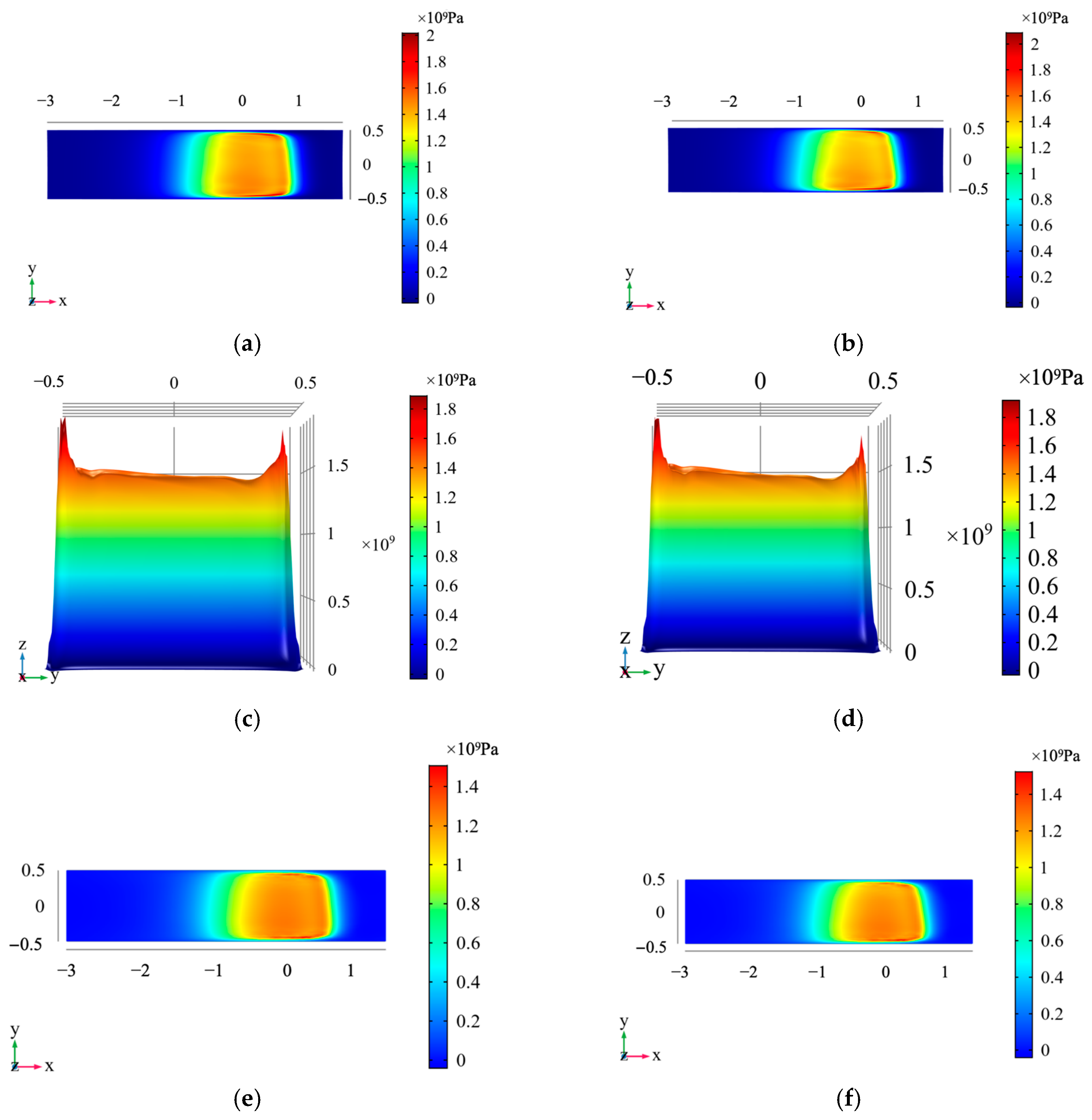
Figure 12 shows that the greater the roller’s tilt angle, the more asymmetric the oil film pressure distribution and the stress distribution of the raceway. When the tilt angle is 0.04°, as shown in Figure 12a,c,e, the oil film pressure on both sides of the roller is 1.89 GPa and 2.01 GPa, respectively, and the maximum pressure on the raceway surface is 1.35 GPa and 1.79 GPa, respectively. When the tilt angle is 0.06°, as shown in Figure 12b,d,f, the oil film pressure on both sides of the roller is 1.84 GPa and 2.02 GPa, respectively, and the maximum stress on the raceway surface is 1.29 GPa and 1.74 GPa, respectively. After the roller tilts, the maximum stress difference on the raceway surface can reach hundreds of MPa.
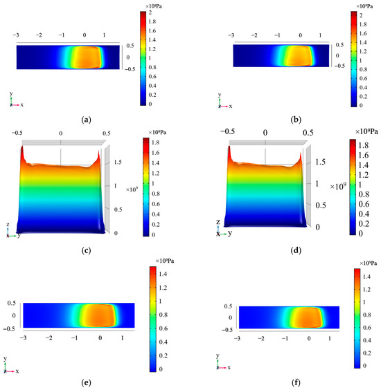
Figure 12.
Oil film thickness and oil film pressure in the contact area between the roller and the raceway. (a,c,e) The roller tilts 0.04°, (b,d,f) the roller tilts 0.06°.
3.2. The Effects of the Roller’s Skew on the Fluid–Structure Interaction of EHL
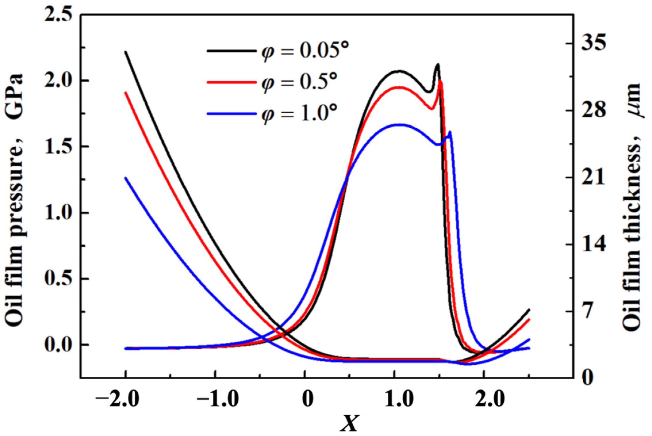
Under the working conditions of the maximum Hertz contact stress of 1.7 GPa and the entrainment speed of 2 m/s, the influence of the roller’s skew on the lubrication state and stress–strain is studied when the roller skews 0.05°, 0.5° and 1°. Figure 13 shows the oil film pressure and thickness in the middle of the roller. The oil film thickness almost does not change with the change of skew angle. The minimum oil film thickness is about 1.67 μm, and the central oil film thickness is about 2.0 μm. The oil film pressure decreases with the increase in skew angle, from about 2.2 GPa to about 1.6 GPa.
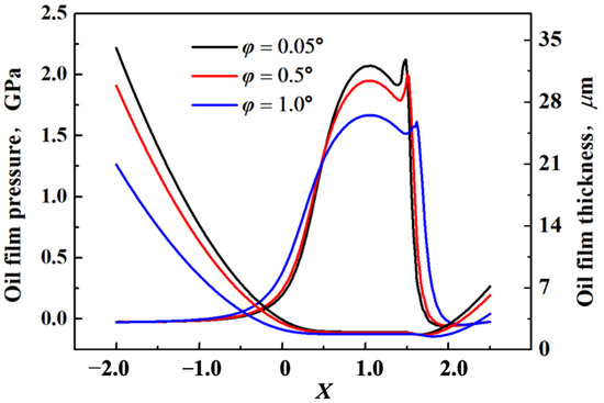
Figure 13.
Oil film thickness and oil film pressure in middle of the roller when the roller skews.
The minimum oil film thickness and the elastic deformation of the raceway decrease with the increase in the roller skew angle, as shown in Table 4.
Table 4.
Minimum oil film thickness and maximum elastic deformation in main contact zone when the roller skews.
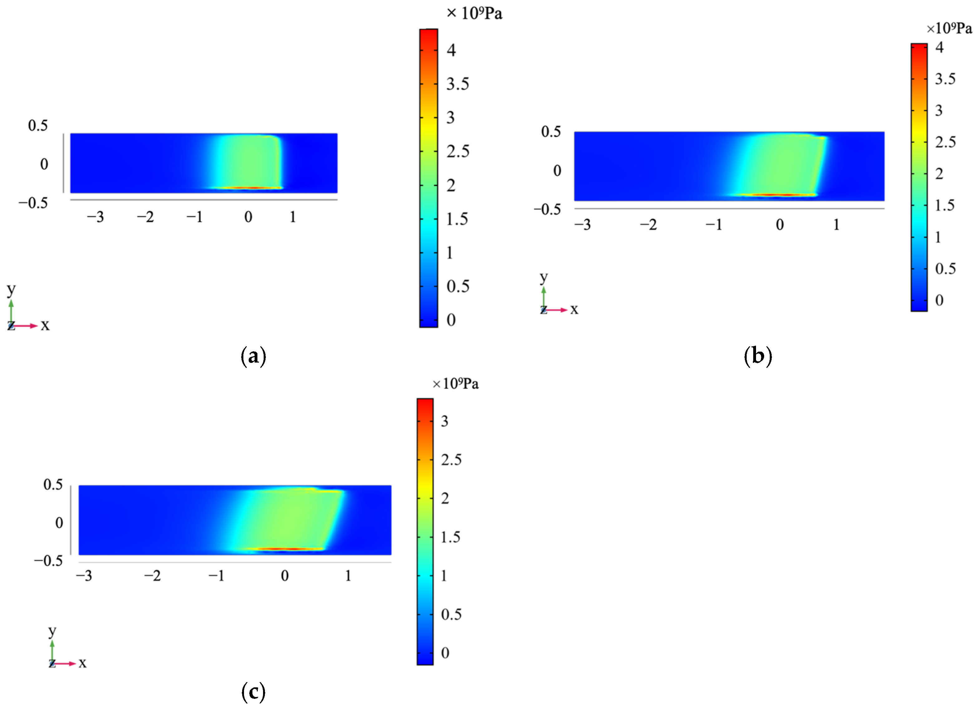
Figure 14 and Figure 15 show the oil film pressure overlooking and three-dimensional views of the rollers with the skew angles of 0.05°, 0.5° and 1.0°. When the roller skews, the oil film pressure tends to one side, the oil film pressure on one side is much larger than that on the other side, and the pressure difference can reach 2~3 GPa. The oil film pressure decreases with the increase in the skew angle. In establishing the geometric model, the dimensionless distance in the y direction is set to 1, and the spatial coordinate value in the y direction is ranged from −0.5 to 0.5.
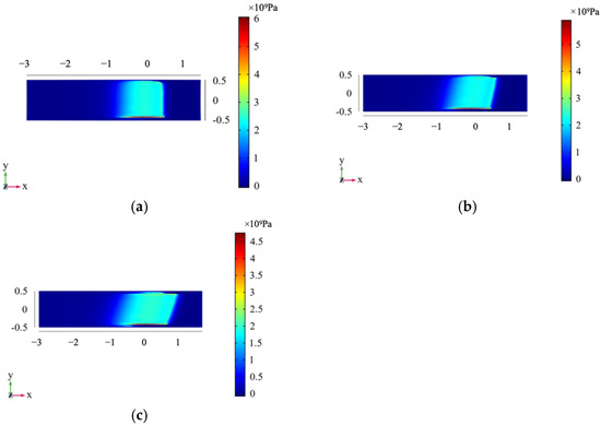
Figure 14.
Oil film pressure in top view when the roller skews different angles: (a) oil film pressure in top (x–y) view when roller skews 0.05°; (b) oil film pressure in top (x–y) view when roller skews 0.5°; (c) oil film pressure in top (x–y) view when roller skews 1.0°.
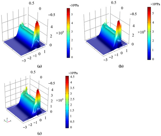
Figure 15.
Oil film pressure in 3D view when the roller skews different angles: (a) 3D oil film pressure when the roller skews 0.05°; (b) 3D oil film pressure when the roller skews 0.5°; (c) 3D oil film pressure when the roller skews 1.0°.
Figure 16 shows the stress on the raceway surface when the roller skews 0.05°, 0.5° and 1.0°. As the roller skew angle increases, the surface stress gradually decreases. The stress on the raceway surface is about 1 GPa smaller than the oil film pressure, and the maximum stress difference on both raceway sides can reach about 2 GPa.
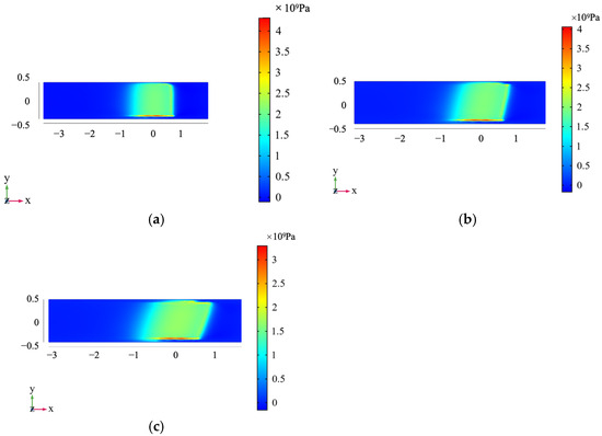
Figure 16.
Stress on the surface after the roller’s skew: (a) the pressure on the surface in the x–y view after the roller skews 0.05° horizontally; (b) the pressure on the surface in the x–y view after the roller skews 0.5° horizontally; (c) the pressure on the surface in the x–y view after the roller skews 1.0° horizontally.
4. Conclusions
This study employs the finite element Full-system approach to develop a three-dimensional fluid–structure interaction (FSI) model for EHL. This model is developed for use with roller bearings. The research examines the coupling effects of surface stress, oil film thickness, and oil film pressure under different operating conditions, focusing on the impact of roller tilt and skew on lubrication performance and stress distribution.
The findings indicate that with a tilt of 0.04° or 0.06°, oil film pressure and thickness in the central region remain stable, while at the large end, pressure and raceway stress increase significantly, resulting in a pressure difference of approximately 0.2 GPa. Conversely, with skew values of 0.05°, 0.5°, or 1.0°, the pressure and thickness in the central region decrease as skew increases. However, one end experiences a sharp pressure rise, while the other end experiences a drop, resulting in a maximum pressure difference of 2.0 GPa.
These results underscore the significance of even slight misalignments in tilt or skew, which can induce asymmetric lubrication conditions, thereby accelerating fatigue wear and reducing the lifespan of bearings. Consequently, precise alignment control and optimised lubrication strategies are imperative for ensuring the reliability and performance of bearings, particularly in high-load, high-speed applications such as aerospace, automotive, and precision machinery.
Author Contributions
Conceptualization, Z.L. (Zhigang Luo); methodology, L.Z.; software, Z.L. (Zhen Li); validation, J.Z.; formal analysis, J.Z.; investigation, X.W.; resources, L.Z.; data curation, L.Z.; writing—original draft preparation, L.Z.; writing—review and editing, X.Y. All authors have read and agreed to the published version of the manuscript.
Funding
This research was funded by the Industry-University-Research Cooperation Project of China Aero-Engine Group, grant number HFZL2022CXY016 and the State Key Laboratory of Robotics and System (HIT), grant number SKLRS202203C.
Data Availability Statement
The original data of this work are available from the authors upon reasonable request.
Acknowledgments
Zhen Li sincerely appreciates Karsten Stahl and Thomas Lohner, who extended such a precious invitation to visit the Gear Research Center (FZG), Technical University of Munich, Germany. He would also like to express his gratitude to Andreas Ziegltrum and Thomas Lohner for their kind guidance and help with COMSOL Multiphysics.
Conflicts of Interest
Authors Lina Zhou, Zhigang Luo, Jingjing Zhang and Zhen li are employed by AECC Harbin Bearing Co., Ltd. Author Xiaodong Wang are employed by Aero Engine Corporation of China. The remaining authors declare no conflicts of interest.
Abbreviations
The following abbreviations are used in this manuscript:
| EHL | Elasto-Hydroynamic Lubrication |
| FDM | Finite Difference Method |
| FEM | Finite Element Method |
References
- Wang, L.Q. Design and Numerical Analysis of Rolling Element Bearing for Extreme Applications; Harbin Institute of Technology: Harbin, China, 2013; pp. 306–335. [Google Scholar]
- Wu, J.Q.; Wang, L.Q.; Lu, Y.F.; Gu, L.; Zhang, C. Geometric modification on mixed lubrication performance of low-speed cylindrical roller bearing. Tribology 2019, 39, 470–478. (In Chinese) [Google Scholar]
- Qiu, L.; Liu, S.; Chen, X.; Wang, Z. Lubrication and loading characteristics of cylindrical roller bearings with misalignment and roller modifications. Tribol. Int. 2022, 165, 107291. [Google Scholar] [CrossRef]
- Chen, X.Y.; Shen, X.J.; Liu, Y.; Xu, W.; Ma, J.J. The analysis of the effect of roller velocity on logarithmic profile roller lubrication condition. In Proceedings of the Sixth National Tribology Conference, Lanzhou, China, 19–22 August 2011; Volume 3. (In Chinese). [Google Scholar]
- Xu, W.; Ma, J.J.; Chen, X.Y. Elastohydrodynamic Lubrication of Finite Line Contacts Part I: A Numerical Analysis of EHL for Finite Cylindrical Roller Contacts. Tribology 1998, 105, 40–45. (In Chinese) [Google Scholar]
- Ma, J.J.; Xu, W.; Chen, X.Y. EHL Properties of Roller Contacts and its Application Part Ⅱ: A Numerical Analysis of EHL for Engineering Logarithmic Roller. Tribology 2000, 1, 65–68. (In Chinese) [Google Scholar]
- Sun, H.Y.; Chen, X.Y.; Liu, C.H.; Yang, P.R. Study of thermal EHL performance of Lundberg profile rollers and the modification of its crowning value. Tribology 2008, 28, 68–72. (In Chinese) [Google Scholar]
- Sun, H.Y.; Chen, X.Y.; Yang, P.R. Thermal elastohydrodynamic lubrication of cylindrical rollers with crown profiled ends at heavy load. Chin. J. Mech. Eng. 2004, 40, 99–104. (In Chinese) [Google Scholar] [CrossRef]
- Luo, B. Quasi-Statics and Transient Thermal EHL Analysis on Tilting Roller Bearing. Master’s Dissertation, Chongqing University, Chongqing, China, 2018. (In Chinese). [Google Scholar]
- Bai, X.R. Analysis of Thermal Elastohydrodynamic Lubrication for Roller Skew in Rolling Bearings. Master’s Dissertation, Qingdao Technology University, Qingdao, China, 2013. (In Chinese). [Google Scholar]
- Huang, H. Study on the Lubrication of Tilting Rollers in Rolling Bearings. Master’s Dissertation, Qingdao Technology University, Qingdao, China, 2012. (In Chinese). [Google Scholar]
- Wu, J.; Wang, L.; He, T.; Gu, L.; Zhang, C.; Lu, Y. Investigation on the angular contact ball bearings under low speed and heavy load with coupled mixed lubrication and quasi-dynamic analysis. Lubr. Sci. 2020, 32, 108–120. [Google Scholar]
- Shirzadegan, M.; Almqvist, A.; Larsson, R. Fully coupled EHL model for simulation of finite length line cam-roller follower contacts. Tribol. Int. 2016, 103, 584–598. [Google Scholar]
- Habchi, W. On the negative influence of roller-end axial profiling on friction in thermal elastohydrodynamic lubricated finite line contacts. ASME J. Tribol. 2020, 142, 111601. [Google Scholar] [CrossRef]
- Habchi, W. Influence of roller-end axial profiling type on lubrication performance in thermal elastohydrodynamic finite line contacts. ASME J. Tribol. 2021, 144, 011601. [Google Scholar]
- Mounayer, J.; Habchi, W. Exact model order reduction for the full-system finite element solution of thermal elastohydrodynamic lubrication problems. Lubricants 2023, 11, 61. [Google Scholar] [CrossRef]
- Schmid, F.; Paschold, C.; Lohner, T.; Stahl, K. Characteristics in hard conformal EHL line contacts. Ind. Lubr. Tribol. 2023, 75, 730–740. [Google Scholar] [CrossRef]
- Higashitani, Y.; Kawabata, S.; Björling, M.; Almqvist, A. An inlet computation zone optimization for EHL line contacts. Tribol. Lett. 2022, 70, 86. [Google Scholar] [CrossRef]
- Habchi, W. A Full-System Finite Element Approach to Elastohydrodynamic Lubrication Problems: Application to Ultra-Low-Viscosity Fluids; Institut National des Sciences Appliquées de Lyon: Lyon, France, 2008; pp. 63–65. [Google Scholar]
- Lohner, T.; Ziegltrum, A.; Stemplinger, J.-P.; Stahl, K. Engineering software solution for thermal elastohydrodynamic lubrication using multiphysics software. Adv. Tribol. 2016, 2016, 6507203. [Google Scholar]
- Alakhramsing, S.S.; de Rooij, M.B.; Schipper, D.J.; van Drogen, M. Elastohydrodynamic lubrication of coated finite line contacts. Proc. Inst. Mech. Eng. Part J J. Eng. Tribol. 2018, 232, 1077–1092. [Google Scholar] [CrossRef]
- Galeao, A.; Almeida, R.; Malta, S.; Loula, A.F.D. Finite element analysis of convection dominated reaction–diffusion problems. Appl. Numer. Math. 2004, 48, 205–222. [Google Scholar]
- Habchi, W.; Eyheramendy, D.; Vergne, P.; Morales-Espejel, G. A Full-system approach of the elastohydrodynamic line/point contact problem. ASME J. Tribol. 2008, 130, 021501. [Google Scholar]
- Dowson, D.; Higginson, G.R. Elasto-Hydrodynamic Lubrication: International Series on Materials Science and Technology; Elsevier: Amsterdam, The Netherlands, 2014. [Google Scholar]
- Marra, V. Simulation Apps Advance Tribology Research. 2018. Available online: https://www.comsol.com/story/simulation-apps-advance-tribology-research-65571 (accessed on 21 March 2025).
- Tan, X.; Goodyer, C.E.; Jimack, P.K.; Taylor, R.I. Computational approaches for modelling elastohydrodynamic lubrication using multiphysics software. Proc. Inst. Mech. Eng. Part J J. Eng. Tribol. 2012, 226, 463–480. [Google Scholar]


Disclaimer/Publisher’s Note: The statements, opinions and data contained in all publications are solely those of the individual author(s) and contributor(s) and not of MDPI and/or the editor(s). MDPI and/or the editor(s) disclaim responsibility for any injury to people or property resulting from any ideas, methods, instructions or products referred to in the content. |
© 2025 by the authors. Licensee MDPI, Basel, Switzerland. This article is an open access article distributed under the terms and conditions of the Creative Commons Attribution (CC BY) license (https://creativecommons.org/licenses/by/4.0/).