Article

Tailored Cage Shapes on Lubricant Migration and Friction Behaviours in Both Ball-Cage and EHL Contacts

1
School of Mechanical and Automotive Engineering, Qingdao University of Technology, 777 Jialingjiang Road, Qingdao 266520, China
2
College of Civil Engineering, Qingdao University of Technology, 777 Jialingjiang Road, Qingdao 266520, China
3
Puyang Xinye Special Lubricating Oil and Grease Co., Ltd., Puyang 457531, China
4
Shanghai Bearing Technology Research Institute Co., Ltd., Shanghai 201801, China
*
Authors to whom correspondence should be addressed.
Lubricants 2025, 13(11), 501; https://doi.org/10.3390/lubricants13110501 (registering DOI)
Submission received: 19 September 2025 / Revised: 8 November 2025 / Accepted: 15 November 2025 / Published: 17 November 2025
(This article belongs to the Special Issue Advances in Lubricated Bearings, 2nd Edition)

Abstract

The cage shape plays a critical role in controlling lubricant distribution and replenishment and enhancing lubrication performance within rolling bearings. This study investigates the effect of four tailored cage shapes on lubricant migration and frictional characteristics at both Ball-Cage (B-C) and Ball-Disc (B-D) contacts. Utilizing a bearing cage friction and lubrication test rig (BCFL), adapted from an optical elastohydrodynamic lubrication (EHL) apparatus, the variation in grease films and friction forces was examined under varying entrainment speeds, grease properties, and grease quantities. Cage-induced lubricant redistribution on the ball surface, replenishment at the B-D contact, and the formation mechanism of thicker film thickness were recognized. The influence of cage design for four distinct shapes on mechanisms enhancing grease lubrication efficiency and friction reduction was examined. The findings provide critical insights for designing next-generation self-aligning cage structures with improved lubrication performance and reduced friction force.

1. Introduction

The majority of bearing failures can be attributed to poor lubrication, leading to unplanned equipment downtime and consequent economic losses [1]. The lubrication state of the contacts between rolling elements and the raceway is largely dependent on the lubricant available on the rolling tracks [2,3]. Specifically, inadequate lubricant supply or insufficient replenishment to the rolling tracks can lead to lubrication failure. To quantitatively correlate lubricant replenishment with film formation ability, a typical ball-on-disc model test method is employed. Previous studies have demonstrated that lubrication states can be significantly improved through strategies such as surface texturing [4,5], application of protective coatings, incorporation of lubricant additives [6], and optimization of contact geometries [7,8,9,10]. These approaches enhance lubricant migration and retention, thereby promoting effective film regeneration during operation. Among the previous studies, enhanced lubricant migration under tailored wettability gradients has been acknowledged. Although the effectiveness of spontaneous lubricant replenishment under surface tension is limited under high-speed conditions, it nonetheless indicates the significant contribution of even a small amount of lubricant to alleviating the lubrication state. In practice, the bearing itself plays an important role in improving lubricant replenishment by regulating lubricant flow, whereas the simple ball-on-disc model contact is unable to fully reproduce this effect. For example, the cage plays a significant role in lubricant redistribution within the bearing. It not only performs the basic function of keeping the position and guiding the motion of the rolling elements but also determines the flow and distribution of lubricants [11]. Thus, a rational design of the cage pocket is beneficial for enhancing lubrication and reducing friction in both ball-cage contact and EHL contact.
Many studies related to cage behaviors have been conducted to investigate their impact on bearing performance. Typical research focuses on collisions and friction under various challenging conditions, such as non-steady operations involving acceleration and deceleration [12], high-speed rotations accompanied by vibrations and high temperatures [13], as well as oscillating conditions [14], and potential issues arising from improper installation [15]. To address these challenges, numerous models have been developed to analyze and discuss friction forces, cage dynamics, and fatigue fracture mechanisms, primarily relying on dynamic analysis methods and computational fluid dynamics (CFD) models [16,17,18,19]. There has been relatively little effort devoted to exploring the effects of lubricant distribution induced by bearing lubrication. In practical operation, effective lubrication plays a crucial role in suppressing friction-induced temperature increases. Ensuring the efficient delivery of lubricant to the rolling track can help to reduce the overall friction. Improving the design of cage structures and materials is an effective way to enhance bearing performance. To achieve this, factors such as friction forces, slip rates, cage stability (centroid trajectories), and stress distribution between the rolling element and the cage must be considered. Particularly, in terms of rolling element-cage contacts, previous studies [20,21,22,23,24] have considered how cage clearance, pocket shape, radius, pocket area, and inertia influence the distribution and migration behaviors of lubricants. In the design and selection of cage materials, traditional choices such as steel and copper are preferred due to their high strength and hardness; however, their influence on the lubrication behavior between the cage and the ball is relatively limited. In contrast, porous polyimide (PPI) has emerged as a promising candidate for cage materials. Its intrinsic microporous structure enables the storage and subsequent release of lubricating oil, thereby maintaining a continuous lubricant supply to the critical contact interfaces [24,25]. Efforts are directed toward employing various methods to enhance oil content, retention, wettability, and the lubricant’s capacity for release and reabsorption under high pressure, temperature, and centrifugal forces [26].
Studies on lubrication dynamics in rolling bearings, particularly in the rolling element-cage contacts, have been explored through various experimental and numerical approaches. The previous dynamic analysis methods have provided critical insights into the friction forces and dynamic behaviors between the cage and rolling element. Meanwhile, experimental approaches have also made significant contributions by enabling direct visualization and measurement of oil flow and friction forces within the ball-cage contact [27]. These experimental methods have elucidated the complex lubrication mechanisms essential for the efficient functioning of rolling bearings. Notably, Li et al. developed an innovative double-contact test rig that simulates friction and surface wear mechanisms simultaneously in both ball-cage (B-C) and ball-disc (B-D) contacts [28]. This dual focus facilitates a more integrated understanding of tribological interactions within the bearing system, acknowledging the interdependence among various contacts. Building on this experimental foundation, Russell et al. designed an advanced experimental apparatus to replicate the dynamic motion of the cage relative to the ball using a transparent glass cage pocket [29]. This setup enhanced the visualization of lubricant movement and elucidated the kinematic influences of cage motion on lubricant distribution. Research undertaken by Liang et al. investigated the relationship between the shape of cage pockets and the corresponding oil distribution pattern within the overall bearing assembly [30]. In their study, the outer ring was replaced by a glass cylinder without a grooved raceway. The principal focus of the experimental setup utilized by Liang et al. was the lubricant behavior in the ball-cage (B-C) contact. However, the obtained results also provided valuable information on the lubrication conditions within the ball-raceway (B-D) contact, as influenced by the cage’s operation. These results consistently identify the cage as a key determinant in the allocation and resupply of lubricants to the critical contact region in the B-D contact.
The shape of the cage pocket impacts the dynamics of angular contact ball bearings [21,22]. For instance, ring-guided cages generally feature nearly cylindrical pockets, whereas ball-guided cages are designed to closely conform to the balls. This close conformity is beneficial as it ensures sufficient contact area for guiding lubricant flow across the ball surface and enhances replenishment in B-C contacts [21,31]. Existing studies indicate the crucial role of the cage in influencing lubricant distribution and replenishment in B-D contacts. Furthermore, specific geometric modifications on the inner surface of the pocket can yield a positive effect. Jin et al. demonstrated that incorporating grooves within the cage pocket walls improves lubricant distribution [32]. Collectively, these findings emphasize the importance of cage pocket design, including both overall pocket shape and local texture, in regulating lubricant flow within the bearing.
This study highlights the pivotal influence of bearing cage geometry on lubricant distribution and frictional behavior in both ball-cage and ball-disc contacts. Unlike previous works mainly focused on grease composition or contact mechanics, the present research emphasizes the structural role of cage design, an aspect rarely explored in bearing lubrication studies. An innovative Bearing Cage Friction and Lubrication (BCFL) rig was developed by integrating a functional cage unit into an optical EHL apparatus [33], enabling simultaneous visualization of grease film behavior and direct friction measurement. Four tailored cage pocket shapes were examined under varied speeds, greases, and lubricant amounts. The results reveal that cage geometry significantly alters grease replenishment and frictional response. These findings establish a clear link between cage structure and lubrication efficiency, offering a novel insight and design strategy for reducing friction and extending bearing life in advanced mechanical systems.

2. Experimental

2.1. Test Apparatus and Scheme

To replicate the contact condition present at the B-D and B-C contacts within a rolling bearing, the BCFL test rig was designed specifically for measuring cage friction and investigating lubrication state transitions. Figure 1 illustrates the structure of the apparatus and the measurement scheme. This setup permits the measurement of both B-D and B-C contact friction, the observation of lubricant interference images, and the acquisition of film thickness data using Dichromatic Interference Intensity Modulation (DIIM) software Ver 1.0 [34]. The experimental apparatus incorporates high-precision servo motors and sensitive sensors, enabling accurate control over the relative positioning and dynamic behavior of the ball and cage components. In the setup, a glass disc coated with Cr and SiO2, along with a ball, is individually driven by servo motors. A charge-coupled device (CCD) camera is used to capture interferograms, images of oil reservoirs surrounding the region, and the rolling track. A comprehensive technical description of this instrumentation is detailed in the referenced work by Jin et al. [33].
Figure 2 compares the variation in storage modulus (G′), loss modulus (G″), and shear stress using an Anton Paar MCR 302 Rheometer with plate-to-plate geometry. The results indicate that the grease samples behave as elastic solids when (G′ >> G″) in the Linear Viscoelastic (LVE) phase, and as elastic-plastic materials with an increase in shear rate beyond the crossover point (yield point). The values of the yield points reflect the viscoelastic properties of the greases. An increase in base oil viscosity corresponds to elevated yield shear stress values.

2.2. Design of Cage Pockets

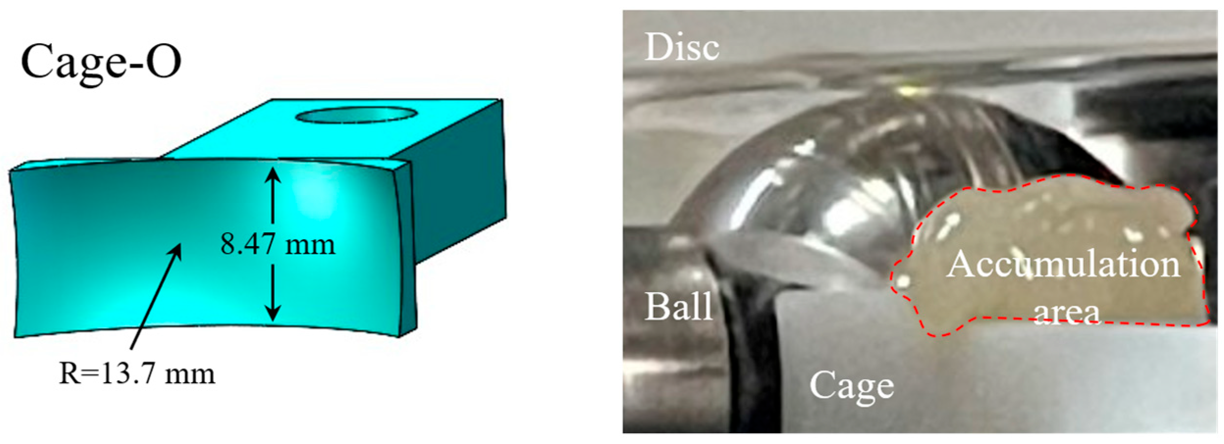
Model cages used in the tests were fabricated via 3D printing method using DSM-8000 photosensitive resin the material. The main focus of this study is to investigate the effect of cage structure on lubricant distribution. The influence of material properties and other related factors lies beyond the scope of the present paper and will be systematically addressed in future work. One quadrant of the complete cage was manufactured in terms of the dimensions of the cage prototype. In previous investigations, it was found that a large amount of grease accumulation occurred on the cage end surface (the pocket shoulders) [33], as shown in Figure 3. This indicates that the grease scraped from the ball surface cannot be effectively re-entrained into the ball-cage clearance. Moreover, the amount of spontaneous lubricant replenishment from the pocket shoulders is insufficient to maintain an acceptable film formation, resulting in starvation in both B-C and B-D contacts. Therefore, it is necessary to overcome the limitations of conventional cages by guiding the migration of the accumulated grease into the B-C contacts through cage shape design.
To investigate the influence of cage shapes on grease migration and distribution, four tailored cage designs were developed. Their configurations are illustrated schematically in Figure 4. The design purpose of Cage-A, which features an additional concave on the inner surface of the pocket, is to examine the grease-scraping behavior from the ball surface and the effect of grease storage on lubrication. To guide lubricant reflow into the ball-cage clearance, Cage-B, Cage-C and Cage-D were developed. The structure of Cage-B is expected to reduce grease scraping and improve grease migration. Cage-C introduces a chamfered structure at the pocket shoulders, primarily aimed at reducing grease accumulation and enhancing reflow. Cage-D further refines this concept by adding channel structures to direct grease flow, facilitating more efficient lubricant replenishment.

2.3. Lubricants and Experimental Procedure

Three model test greases were used, designated G-A, G-B, and G-C. These grease samples were prepared with the same lithium soap thickener and additive-free. The base oil is Polyalphaolefin (PAO) with different viscosities. The main physicochemical properties of these test greases are presented in Table 1. A detailed description of their rheological properties has been given in [33].
The experimental conditions are listed in Table 2. It should be noted that the fixed ball-cage contact gap used in the present test rig is a simplification, as actual bearings experience dynamically varying gaps due to cage motion and load fluctuations. All tests were performed at a constant slide-to-roll ratio (SRR), defined as ξ = 2(ubud)/ue, where ub and ud are the speeds of the ball and disc, respectively, and ue is the entrainment speed. Given that the SRR in rolling bearings typically varies between 0 and 0.1, a representative value of ξ = 0.05 was selected for this study. Table 3 presents various ub and ud values at ξ = 0.05. Prior to each test, a fixed amount of 2.0 g fresh grease was applied to the glass disc surface. Film thickness and friction in B-D contacts, along with the time-resolved friction in B-C contacts, were recorded to identify the influence of cage shape on lubrication state transitions.

3. Results and Discussion

3.1. Effect of Entrainment Speed on Lubrication and Friction

In this section, the evolution of grease film and friction over time in the B-C and B-D contacts with different cage pocket shapes were investigated with Grease-B. The lubrication state transitions from fully flooded to different levels of starvation were recognized. To intuitively indicate the lubrication state, the corresponding film thicknesses at λ = 1.0 and λ = 3.0 were calculated based on the surface roughness of the steel balls and glass discs shown in Table 2, and these have been marked in the following figures.
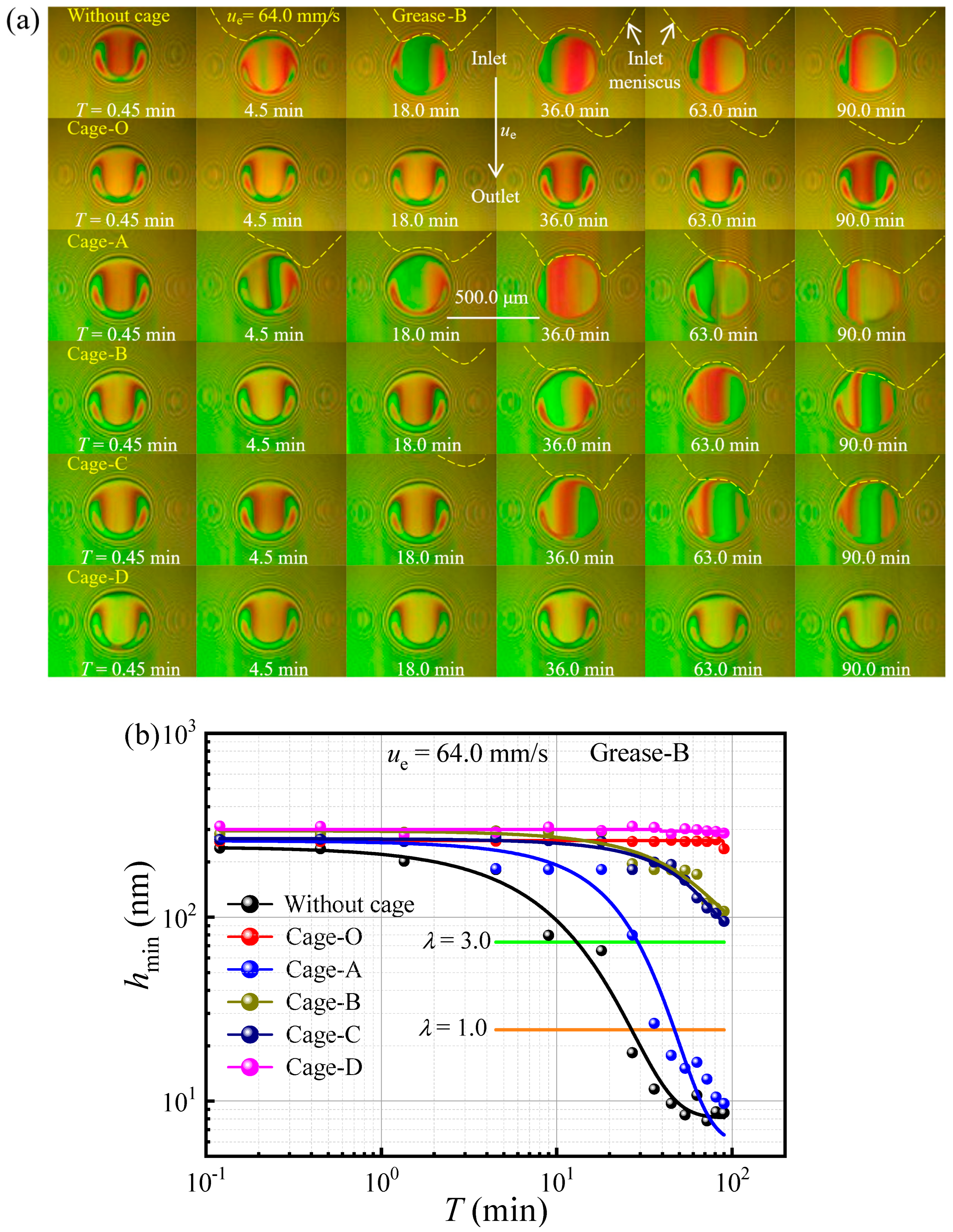
Figure 5 compares the variation in interference images and minimum film thickness (hmin) against time with different cage pocket shapes at ue = 64.0 mm/s. As depicted in Figure 5a, in the absence of a cage, the inlet oil-air boundary (marked by a yellow dotted line) has reached the contact edges within a short running period of 4.5 min, causing starvation. As the operation progresses, the contacts gradually deteriorate and ultimately result in a depleted contact state. The location of this meniscus is governed by the balance achieved between the rate of lubricant loss to the track sides and the rate of replenishment supplied by the oil ridges [35]. In contrast, the inlet lubricant supply is improved in different trends as the tailored cages are used. The imposition of a conventional cage (Cage-O) significantly impacts both the inlet lubricant supply and film formation; notably, the inlet meniscus does not appear until T = 36.0 min. For Cage-A, the inlet meniscus is observed to rapidly approach the contact edge, eventually depleting the inlet and resulting in severe starvation. Cage-B and Cage-C alleviate starvation by slightly enhancing the lubricant supply, which leads to partial film recovery. Unlike other cage geometries, Cage-D exhibited no inlet meniscus during the entire test, evidencing superior film formation and a fully flooded lubrication regime with a typical EHL profile. The results indicate that an improper cage shape is detrimental to lubricant replenishment, leading to severe starvation. The underlying mechanisms contributing to these observations will be further investigated in subsequent sections.
The corresponding minimum film thickness (hmin) over time (T) is also shown in Figure 5b. For both the without cage and Cage-A conditions, film thickness exhibited a pronounced decline over time, indicating severe lubrication degradation and suggesting a gradual progression toward grease starvation. A slight improvement is observed with Cages B and C, which effectively mitigate the sharp decline in film thickness. Although these designs still result in a gradual decrease in film thickness over time, they demonstrate substantially enhanced replenishment, thereby sustaining the lubrication film higher than Cage-A. In contrast, Cage-O and Cage-D maintained the film thickness at a consistently high level throughout the test, indicating that these cage geometries significantly enhanced lubricant replenishment and sustained a stable lubricating film. This demonstrates the proper cage shape can provide a continuous and sufficient lubricant supply, thereby maintaining a fully flooded lubrication state.
Figure 6 presents the evolution of friction forces (FF) in both B-D and B-C contacts over time for different cage pocket shapes, tested with Grease B at ue = 64.0 mm/s. The results reveal distinct friction behaviors in B-D for different cage pocket shapes in Figure 6a. The results show that, in the absence of a cage, the friction force increases sharply due to lubricant starvation, indicating a transition from fully flooded to mixed or boundary lubrication conditions. Conversely, the imposition of a cage significantly reduces the friction force. Although friction for these tailored cage geometries continues to increase gradually, both the rate and magnitude are dictated by the lubrication regime characteristic of each design. Among the tested cage shapes, Cage-D exhibits superior performance by maintaining a remarkably low and stable coefficient of friction throughout the test duration. This exceptionally stable frictional response directly correlates with the sustained and high minimum film thickness observed for Cage-D, as shown in Figure 5.
In contrast to the B-D contacts, the evolution of friction behavior in B-C contacts exhibits a different trend in Figure 6b. Cage-A exhibits the lowest friction force, suggesting an optimized lubricant feed-loss balance in B-C contact, although the curve presents significant fluctuations, especially in the final running phase, potentially due to stick-slip phenomena induced by localized lubricant starvation. Cage-B, Cage-C, and Cage-D demonstrate moderate friction forces, with relatively stable behavior over the initial stages, followed by increased fluctuations towards the end of the test, possibly indicating the occurrence of mixed lubrication due to the film thickness decay. Cage-O presents the highest friction force due to insufficient dynamic pressure in B-C contact. The fluctuations observed across several curves during the final running phase suggest a common underlying mechanism, such as grease degradation, oil starvation, or changes in contact conditions, leading to increased friction and unstable lubrication behavior.
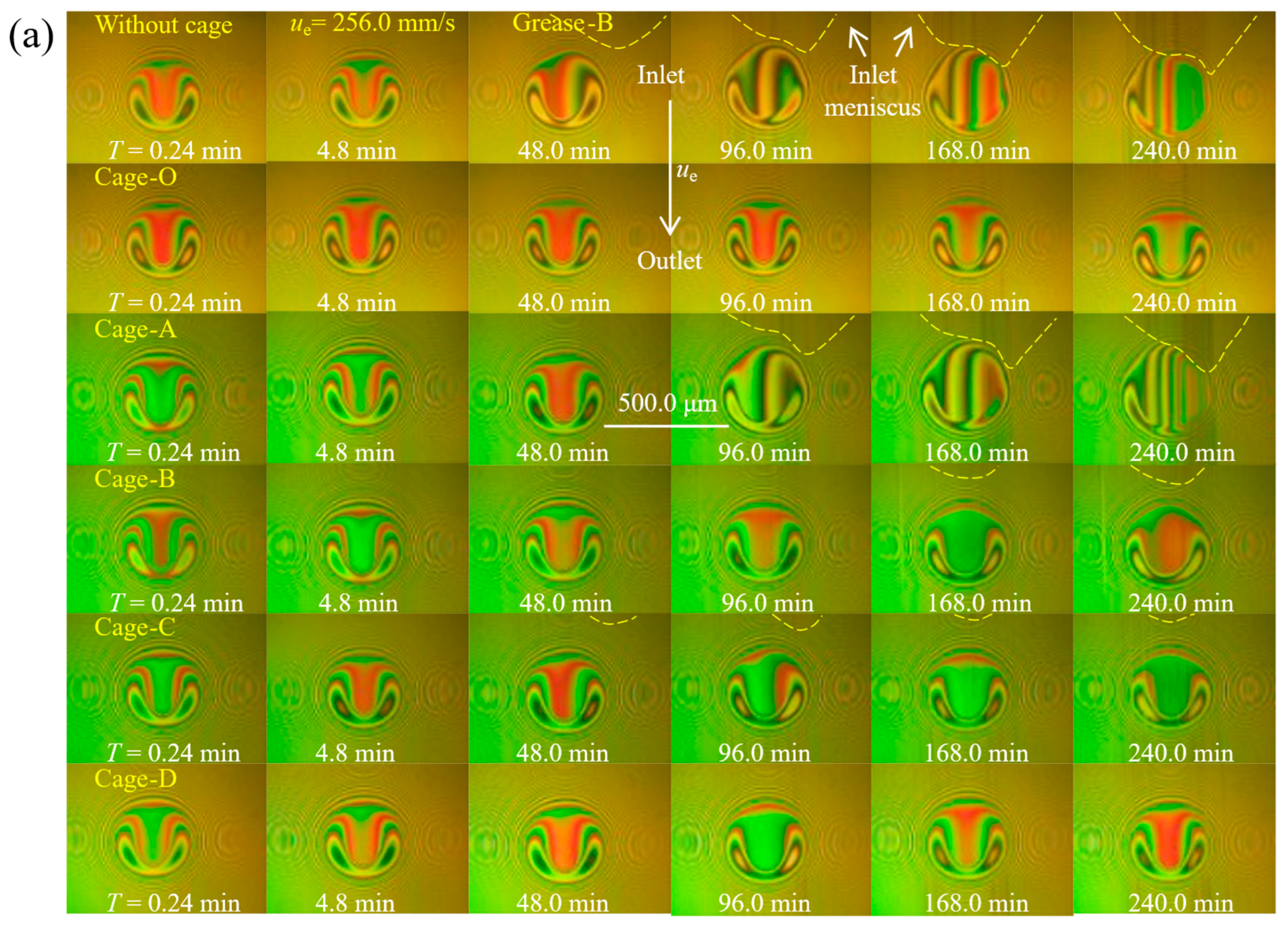
To investigate the impact of entrainment speed on film thickness and friction force, the experiment was conducted at a higher entrainment speed at ue = 256.0 mm/s. Figure 7 presents the evolution of the interference images and the corresponding minimum film thickness over time. At this higher speed, the increased shear rate within the contact zone promotes grease degradation, releasing more bleeding oil and improving lubrication. As illustrated in Figure 5, this enhancement is particularly evident in the absence of a cage, especially when compared with the performance observed at lower speeds. While the tailored cages generally improve lubricant supply and film formation, their effectiveness depends on the cage shapes. For Cages-O, B, C and D provide an enhancement inlet supply that effectively mitigates starvation. In the case of Cage-A, the rapid progression of the inlet meniscus to the contact edge induces a significant distortion in the film profile. Figure 7b shows that Cage-A and the no-cage configuration follow a similar film thickness trend: it remains stable at the beginning, then drops abruptly as a result of lubricant starvation. The other cage shapes consistently maintain a relatively high and stable film thickness, with only a slight decrease throughout the duration of the test.
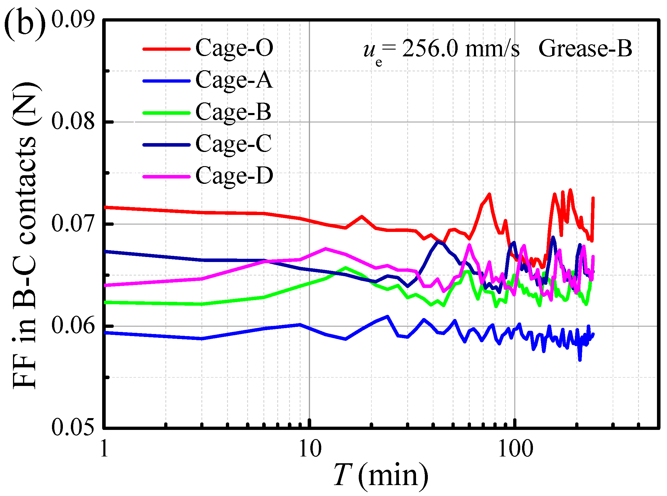
Figure 8 presents the friction force curves for both B-D and B-C contacts over time at ue = 256.0 mm/s. In the absence of a cage, exhibits the highest friction due to inadequate lubricant replenishment, consistent with the results in Figure 6. In the tailored designs, Cage-A shows a consistently higher B-D friction force than the others, owing to insufficient oil film formation. In contrast, the other tailored cages maintain low and stable friction throughout the testing period, and a slight increase in the final phase due to starvation. Figure 8b depicts the friction force in B-C contact at ue = 256.0 mm/s. Consistent with trends at lower speeds, Cage-A exhibits the lowest friction force, as the severe starvation at the B-D contact corresponds to a lower lubricant film in the B-C contact. Following this, the moderately higher friction in Cages B, C, and D is attributable to their enhanced lubricant replenishment, which increases lubricant reflow into the B-C contact and thereby generates greater viscous drag. Consequently, Cage-O exhibits the highest friction, a result of its larger B-C contact area. The increasingly pronounced friction fluctuations observed for all cages in the latter half of the test are attributed to the combined effects of lubricant degradation and instabilities distribution due to starvation.
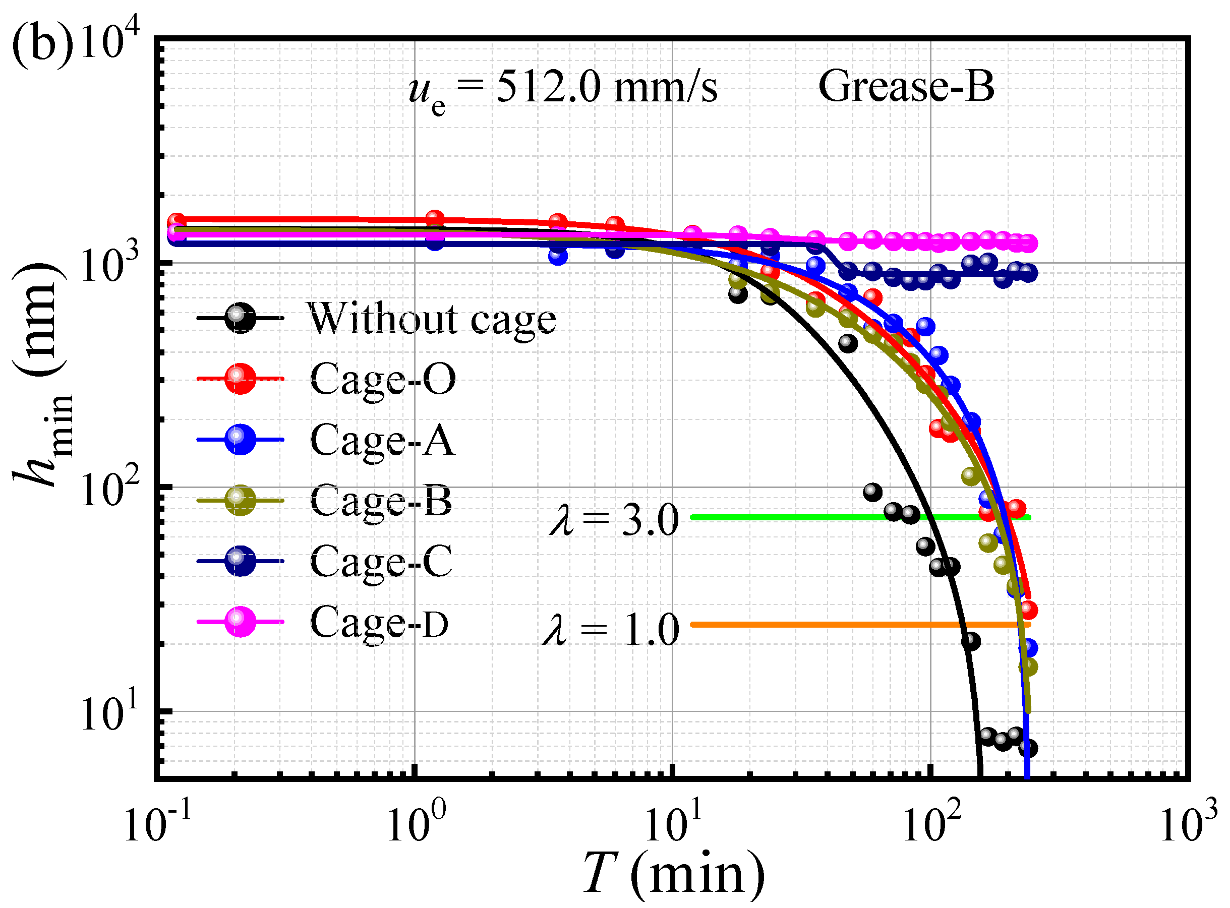
As the entrainment speed increases to ue = 512.0 mm/s, maintaining adequate lubricant replenishment becomes more challenging due to centrifugal forces. Figure 9 depicts the evolution of interferometry images and hmin over time for various cage shapes. The results indicate that the contacts initially display a typical elastohydrodynamic (EHL) film distribution. During the test, an inlet meniscus develops, the extent of which depends on the level of lubricant starvation. As shown in Figure 9b, Cage-D maintains a stable, fully flooded film and a high hmin throughout the test. In contrast, for the other cage shapes, the inlet meniscus gradually approaches the contact edge, causing film distortion, an asymmetrical inlet, and a subsequent rapid decay in film thickness.
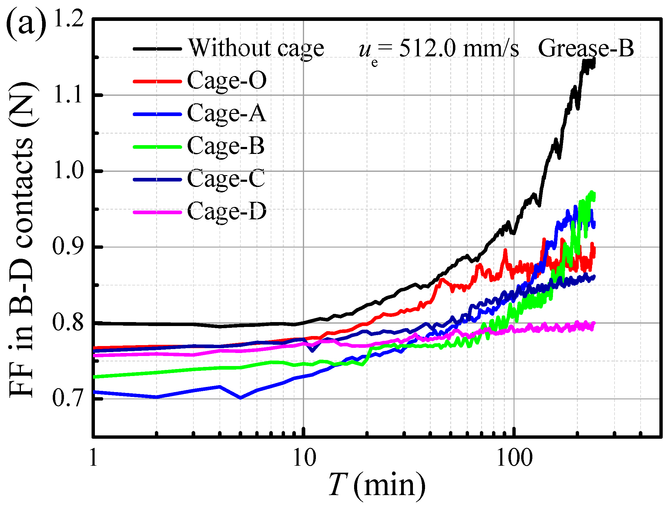
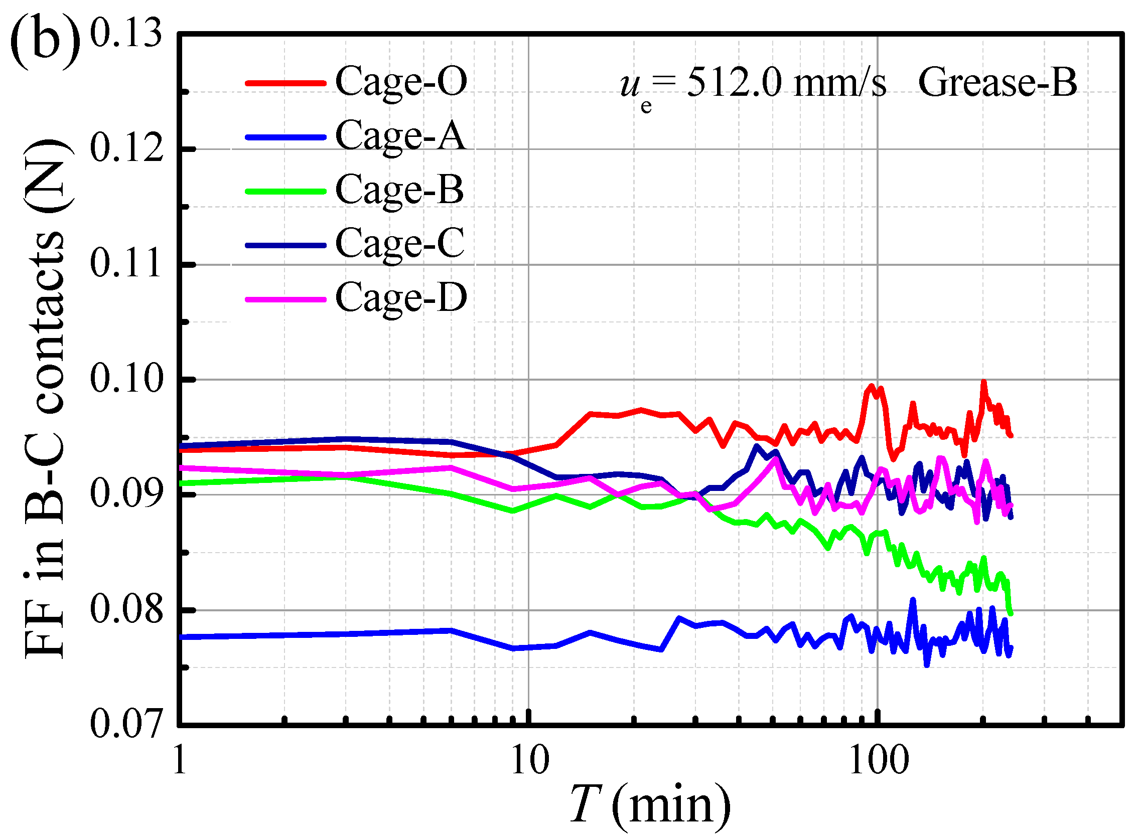
Figure 10 shows the corresponding friction force at ue = 512.0 mm/s. The irregular increase and subsequent stable process can be attributed to factors including entrainment speed, grease degradation, starvation (inlet meniscus), and the lubrication state. The results suggest an initial stable and increasing phase in the B-D contact, where the curve variation depends on the lubrication state shown in Figure 9. As shown in Figure 10b and consistent with the trends observed at lower speeds (Figure 6 and Figure 8).

3.2. Effect of Base Oil Viscosity on Evolutions of Film and Friction

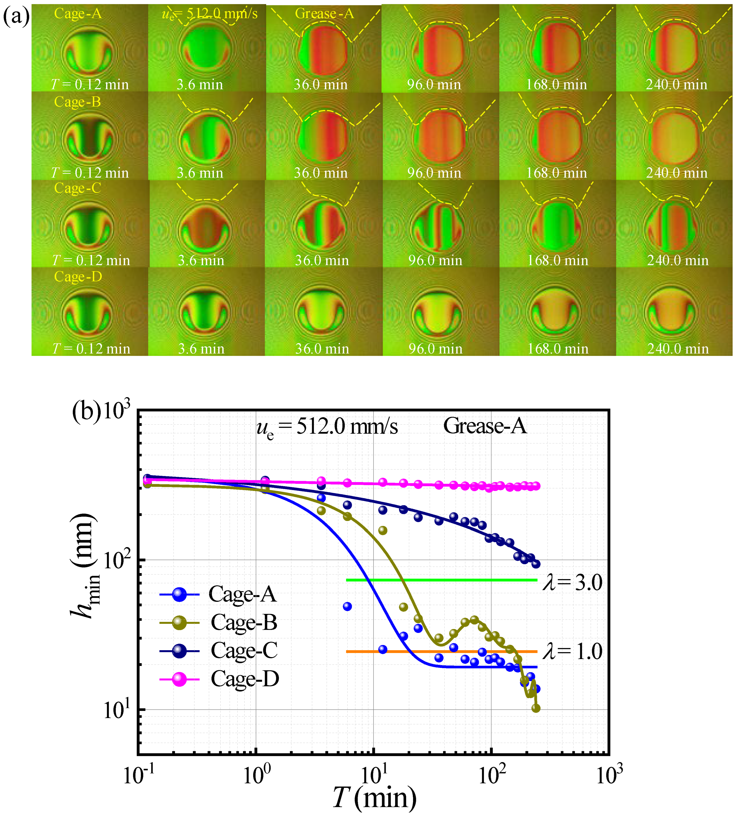
The base oil viscosity influences lubricant flow within the B-C contact clearance as well as replenishment in both the B-C and B-D contacts. To compare the effect of base-oil viscosity on lubricant replenishment and friction for different cage shapes, Figure 11 shows the evolution of interferometric images and the corresponding film-thickness profile over time. The measurements were obtained using Grease A, which contains a lower-viscosity base oil. Compared to the results shown in Figure 9, which were obtained using a grease B with a higher base oil viscosity, the degree of starvation is observed to be more severe. This phenomenon is primarily governed by the balance between lubricant replenishment, which is related to the grease’s yield stress, and lubricant loss due to shearing. This interplay impacts the distinct distribution of grease within the contacts. Although Grease A has the lowest yield shear stress, it releases less oil through bleeding in the ball-disc contact and, as a result, is more easily displaced to the sides of the rolling track by the contact pressure. For instance, with Cage-C, a stable inlet meniscus forms within 3.6 min when using Grease A, whereas Grease B exhibits slight starvation under the same conditions. Furthermore, the images confirm that Cage-D significantly improves lubricant replenishment, enabling the formation of a fully flooded EHL film. For the other tailored cage pocket shapes, the inlet meniscus gradually appears, and the degree of starvation decreases progressively from Cage-A to Cage-C. Figure 11b illustrates the variation in film thickness for the four tailored cage shapes. The film thickness is observed to increase progressively from Cage-A to Cage-D. In the case of Cage-D, the film thickness remains stable at its highest level. This shape effectively maintains a sufficient lubricant supply at the inlet under various lubricating conditions, owing to enhanced replenishment.
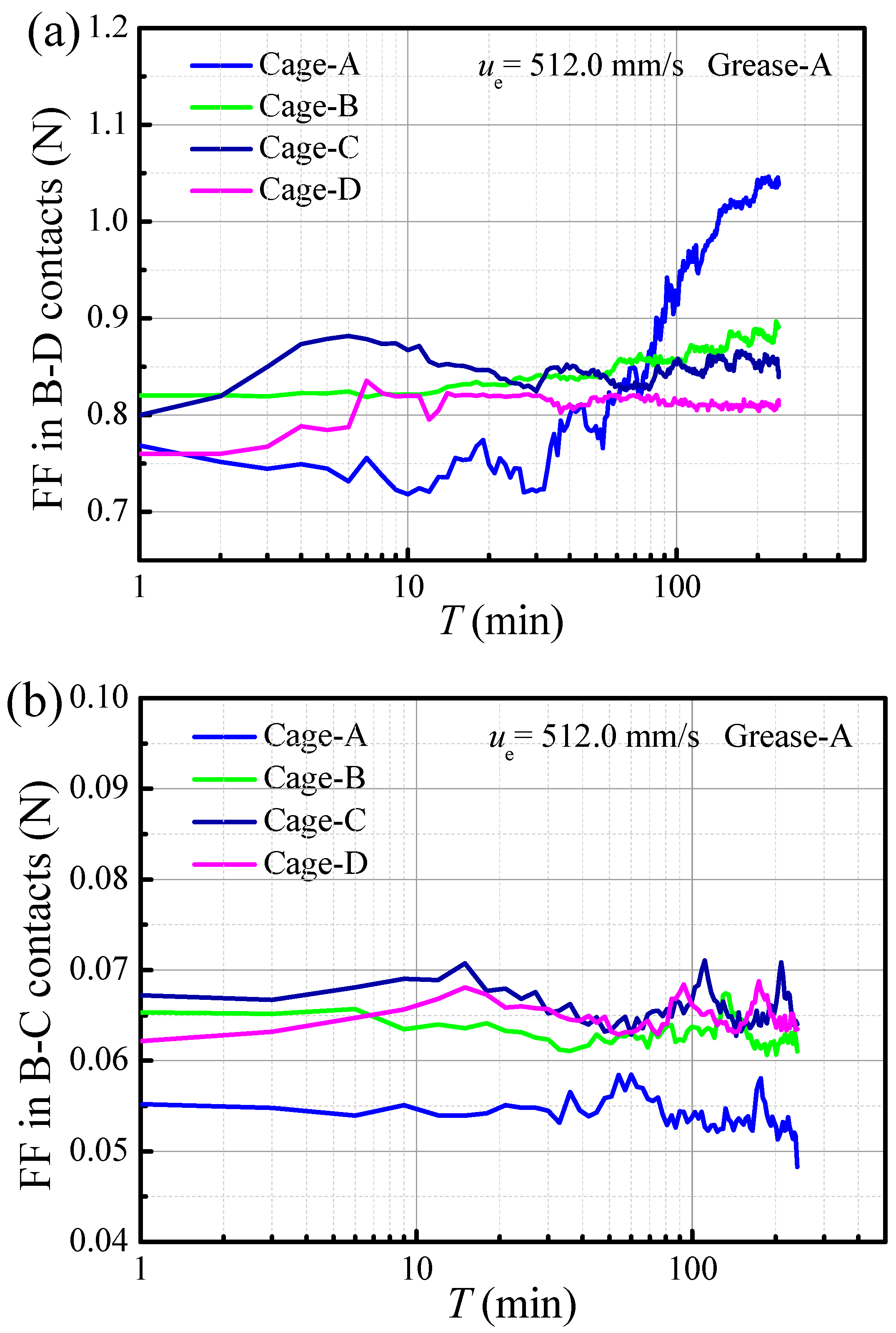
Figure 12 presents the corresponding evolution of the friction forces. Consistent with the film thickness results presented in Figure 11, the relative performance trends among the various cage shapes are maintained. For example, Cages A, B, and C continue to exhibit severe starvation; Cage A again exhibits the highest friction in the B-D contact but the lowest friction in the B-C contact. These results demonstrate that base oil viscosity has a significant impact on both replenishment and film formation. While the qualitative friction trends are similar, the friction values measured with Grease A are distinctly lower than those recorded for Grease B. This is attributed to the lower base oil viscosity of Grease A, which leads to reduced viscous drag.
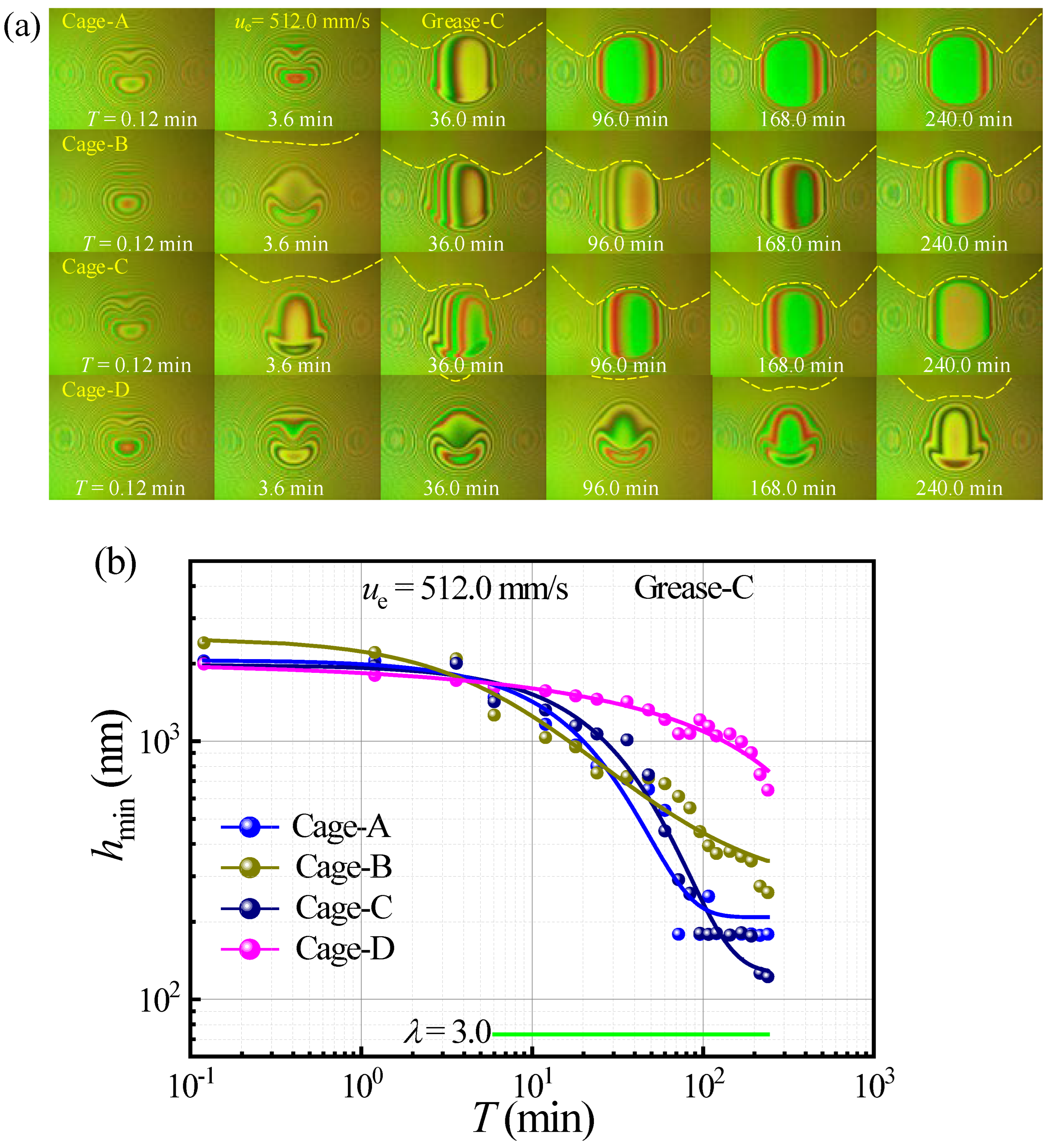
Nevertheless, when using Grease-C, which features a higher base oil viscosity, the evolution of the images and its thickness changes, as depicted in Figure 13. The images for Cage-A to Cage-C reveal that the inlet meniscus forms and approaches the contact zone, leading to distortion of the EHL film. Interestingly, while an inlet meniscus also emerges and impacts the film shape for Cage-D, the lubrication state transitions over time from fully flooded to slightly or mildly starved [31,35]. These results indicate that even for the most effective tailored design, Cage-D, the combination of high speed and the high base-oil viscosity of Grease-C (along with its corresponding high yield shear stress) hinders lubricant replenishment. This effect occurs at both the rolling track (B-D contact) and the cage shoulder (B-C contact). This results in rapid film decay and starvation, as illustrated in Figure 13b. This observed behavior can be attributed to the balance between the shear-induced expulsion of lubricant from the track and a replenishment mechanism that is controlled by the yield shear stress of the bulk grease [35]. The higher base oil viscosity in Grease-C results in a higher yield shear stress, which hinders replenishment and leads to improper distribution.
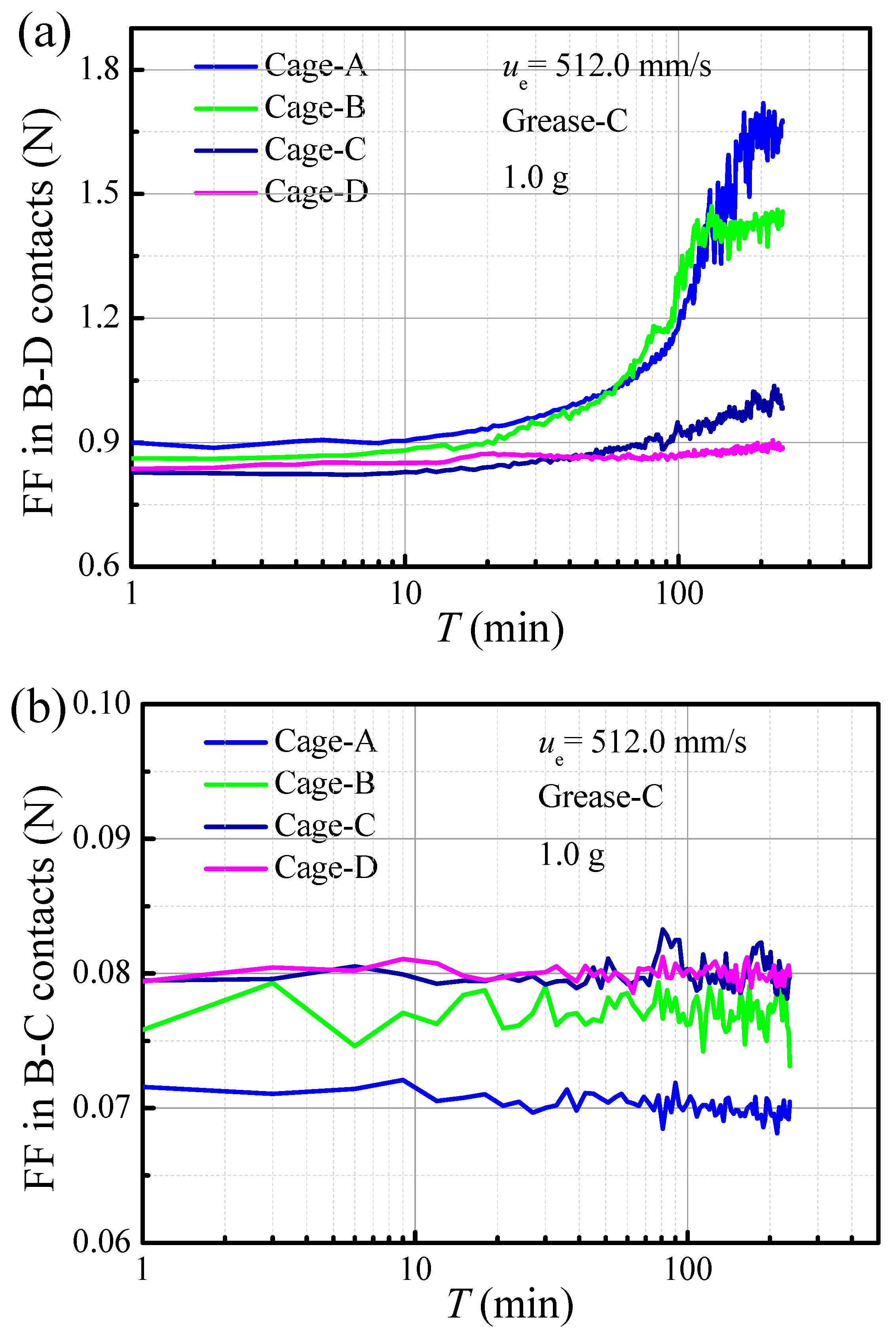
Figure 14 illustrates the evolution of friction forces when using Grease-C at ue = 512.0 mm/s. The observed friction behavior differs from that shown in Figure 10 and Figure 12. In this case, the friction forces are initially stable but subsequently increase, with the rate of increase depending on the level of starvation associated with four tailored cage shapes. This behavior is primarily attributed to the lubricant replenishment states in the B-D contact, as previously detailed in the discussion of Figure 13. The friction trend directly corresponds with the film thickness variations, resulting in Cage-A exhibiting the highest friction in the B-D contact, followed by Cage-B, Cage-C, and Cage-D, respectively. These results indicated that the friction force and film thickness in B-D contact is not significantly impact the friction force in B-C contact.

3.3. Effect of Supply Grease Amount on Film Evolution and Friction

The quantity of grease supplied is known to influence lubricant distribution and replenishment in the B-D and B-C contacts [21,30,32]. To investigate the specific effect of a limited lubricant supply on EHL film formation, experiments were conducted by applying a small quantity (1.0 g) of Grease-C to the glass surface. Figure 15 presents the evolution of the images and grease film in the B-C and B-D contacts using a limited 1.0 g at ue = 512.0 mm/s. As observed in Figure 15a, the reduced quantity of grease causes significantly more severe starvation compared to the 2.0 g supply shown in Figure 13. The images confirm that a smaller grease amount reduces replenishment, causing the inlet meniscus to appear earlier and promoting a rapid transition to severe starvation. Specifically, the contact zone operates under EHL regime, in contrast to the hydrodynamic lubrication shown in Figure 13. These results suggest that a limited grease supply not only affects the lubrication state by accelerating the transition from fully flooded to starved conditions, but also influences the effective viscosity of the lubricant entering the contact. The latter effect arises from increased shear within the inlet region, which alters the lubricant’s rheological behaviour [36]. Furthermore, direct observation images confirm that the Cage-D design promotes greater lubricant reflow into the rolling track compared to other cage shapes [2]. However, even for the optimal shape of Cage-D, an inlet meniscus gradually forms after 36.0 min, leading to a corresponding distortion of the film shape.
Figure 15b displays the evolution of film thickness over time, showing a general decline for all tested cage designs. For Cage-A, the film thickness is initially stable before undergoing a rapid decay, a trend consistent with the findings in Figure 13. In contrast, the other cage shapes exhibit more gradual decreases in film thickness, with the rate of decline depending on the degree of starvation. The cage shapes exhibit a distinct performance ranking based on their replenishment performances, which directly determines their effectiveness in maintaining film thickness in ascending order from Cage-A to Cage-D. These results highlight the critical influence of cage shapes on lubricant replenishment, which is essential for ensuring adequate film formation within the EHL contact, particularly under starved conditions.
Figure 16 compares the friction forces in the B-D and B-C contacts for the tailored cage shapes. For Cage-A and Cage-B, the friction force increases rapidly due to a growing degree of lubricant starvation. In contrast, Cage-C and Cage-D only show a slight increase in friction toward the end of the test, which is attributed to their excellent replenishment capabilities. Figure 16b illustrates the influence of cage shapes on the B-C contact friction force when using a 1.0 g grease. The trend, characterized by an initial stable period followed by fluctuations, is similar to that shown in Figure 14. However, the value of the friction force is lower compared to the case with a 2.0 g grease supply. This reduction is primarily attributed to the decreased quantity and effective viscosity of the lubricant within the B-C contact. These findings demonstrate that the initial quantity of supplied grease is a critical factor governing lubricant replenishment, which in turn impacts the tribological performance of both the B-C and B-D contacts.

4. Discussion and Mechanisms

The above results indicate that entrainment speed, viscosity of base oil, and the amount of grease supplied, particularly in contact with different cage pocket shapes, significantly influence the evolution of the grease film and the friction behavior in B-D and B-C contacts. This section is dedicated to elucidating the fundamental mechanisms that govern the observed lubrication phenomena.

4.1. Effect of Cage on Lubrication State Transition

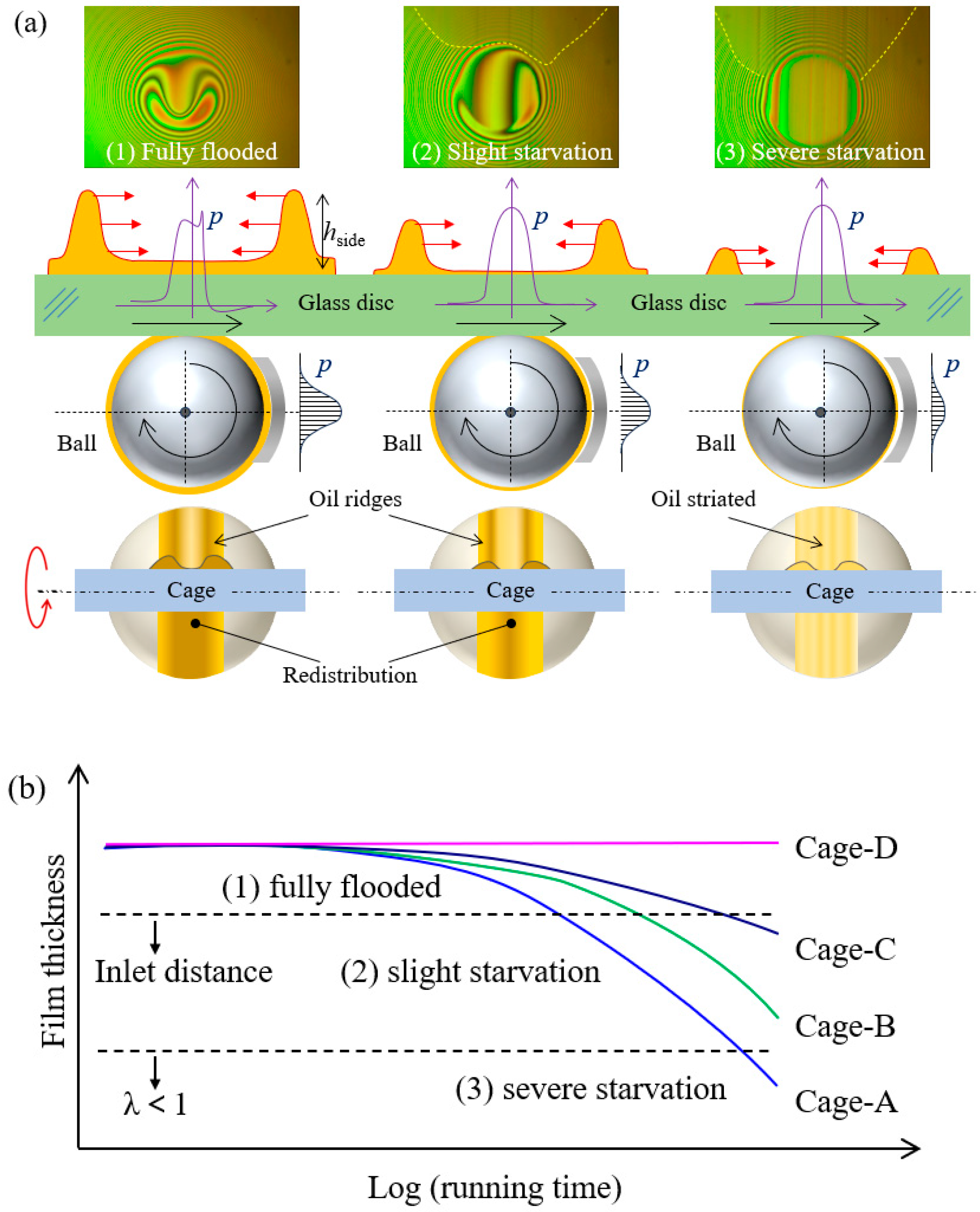
Above observations reveal that the evolution of grease film and friction force exhibits variations in the inlet meniscus distance, leading to differing degrees of starvation depending on the cage pocket shapes. Based on experimental results, three lubrication states can be distinguished over time, depending on lubricant distribution, replenishment, and starvation: (1) fully flooded, (2) slight starvation, and (3) severe starvation. Figure 17 presents schematic diagrams illustrating the evolution of grease film and lubricant distribution in the B-C and B-D contacts. The forces between ball-cage are transmitted through the oil film in the gap by the hydrodynamic pressure (p) generated [37]. The red arrows represent the tendency of the lubricant on the track surface to migrate toward the central region of the track.
During the initial fully flooded phase, the grease entering the contact zone exhibits shear-thinning behaviour. This process disperses the thickener particles and facilitates the development of a thick lubricating film [35]. This initial phase represents a transient, fully flooded condition independent of replenishment, rapidly transitions to a channeled state in a process governed by grease properties, shear rate, and loading [38]. Once these channels are established, the lubrication mechanism transitions to a bleed-dominated phase, where the rolling track is replenished by bleeding oil released from residual layers on the surfaces and from the grease reservoir within the cage [35,38]. An enhanced flow of bleed oil into the rolling track maintains a typical fully flooded EHL film, leading to reduced friction and a stable film shape. Compared to the absence of cage conditions, this duration is extended by replenishment from the cage, indicating its significant contribution to this process [32]. Furthermore, the cage also governs lubricant distribution. During the “fully flooded” phase, a large volume of grease is forced onto the cage surface and into the B-C contacts. Subsequently, bulk grease flow happens as the moving balls push grease across the cage, forming the channels [38]. However, in practical applications of rolling bearings, the churning and bleeding phases of grease lubrication can have a considerable duration, typically lasting from several to more than ten hours. This period is determined by several factors, including grease properties, contact geometry, cage design, and ball dynamics.
Next, the lubrication state transitions to the slight starvation phase due to starvation. To quantitatively assess the onset and the degree of starvation, different criteria have been defined to correlate the inlet conditions with the film thickness [39,40]. During this stage, an increasing amount of grease is pushed into sides of the rolling track. Concurrently, a significant amount of lubricant becomes immobilized within the cage, and it reflows to the B-C contact is restricted, leading to starvation. The degree of starvation is determined by factors including entrainment speed, grease properties, lubricant quantity, and cage pocket geometry [41]. A key characteristic of this starved lubrication state is the inlet meniscus approach to the contact edge distorting the film shape. However, despite under the starvation, a higher film thickness is still maintained in B-D contact. During this phase, the pressure gradient pushes amount of bleeding oil into the side bands adjacent to the contact track. Simultaneously, the lubricant depletion rate exceeds the replenishment rate, which relies primarily on lubricant transfer from the cage to the ball surface.
When the reflow of bleeding oil to the rolling track is insufficient (λ < 1), the residual layer undergoes severe disruption, result in rapid film decay and the transition into the severe starvation phase. The lubricant at the inlet originates from two sources: (1) track replenishment, which provides only a minor contribution, and (2) lubricant carried by the ball, primarily supplied by the cage, which forms oil striations on the ball surface. The formation of these striations on the ball surface is governed by surface tension, while their shape is indicative of the degree of starvation [29,33].

4.2. Effect of Cage on the Film Formation and Replenishment

The enhanced inlet supply and increased film thickness observed in Figure 5 and Figure 7, a finding corroborated by previous research [31,32,34], beneficial impact of the cage effect on lubrication performance. In the absence of cage, lubricant replenishment depends on transfer from side reservoirs and oil ridges into the rolling track. In contrast, the imposition of a cage enhances the replenishment mechanism, leading to maintain stability and a thicker lubricant film. As illustrated in Figure 18, the presence of a cage facilitates the accumulation of grease on its surface, which forms distinct deposits that connect with the oil ridges on the ball. This phenomenon, driven by the cage, contributes to thicker film lubrication through two primary mechanisms: (1) enhanced reservoir capacity: the cage indirectly increases the oil ridge volume, effectively enlarging the lubricant reservoirs and ensuring more lubricant for replenishment on B-D contact; (2) direct lubricant redistribution: the cage facilitates direct lubricant transfer onto the ball surface through B-C contact clearance. This direct delivery of lubricant facilitates abundant lubricant flow into the B-D contact, thereby promoting the formation of a thicker and more stable lubricating film. These mechanisms indicate the critical role of the cage, which not only enhances lubricant replenishment but also facilitates the formation of a thicker lubricating film within the EHL contact, thereby reducing friction force.
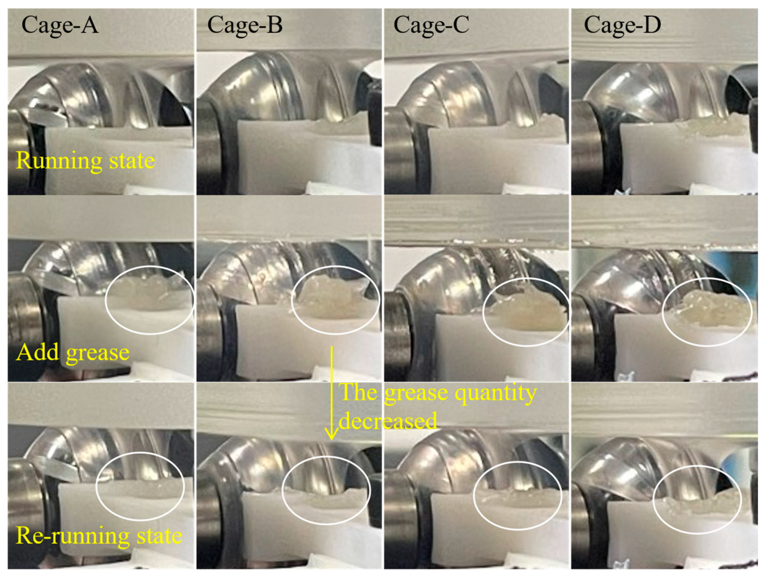
Notably, the lubrication states of B-D contact (EHL) differ significantly from B-C contact (HL) [33]. As analysis of the lubricant flow at the B-C contact is fundamental to understanding the lubricant dynamics and distribution between cage and ball contact clearance. To observe the evolution of lubricant distribution, 0.2 g of grease was applied to a fixed location on the cage. Figure 19 compares the grease distribution in B-C contact with running and re-running. It can be observed that the grease applied to the cage adheres to and redistributes on the surface of the ball, subsequently influencing its distribution on the disc surface. The rapidity of this transfer indicates the entrainment effect enhance more grease onto the ball surface. This mechanism can be employed to enhance lubrication by ensuring more effective grease replenishment to the rolling track.

4.3. Comparisons of Replenishment and Distribution with Four Cage Pocket Shapes

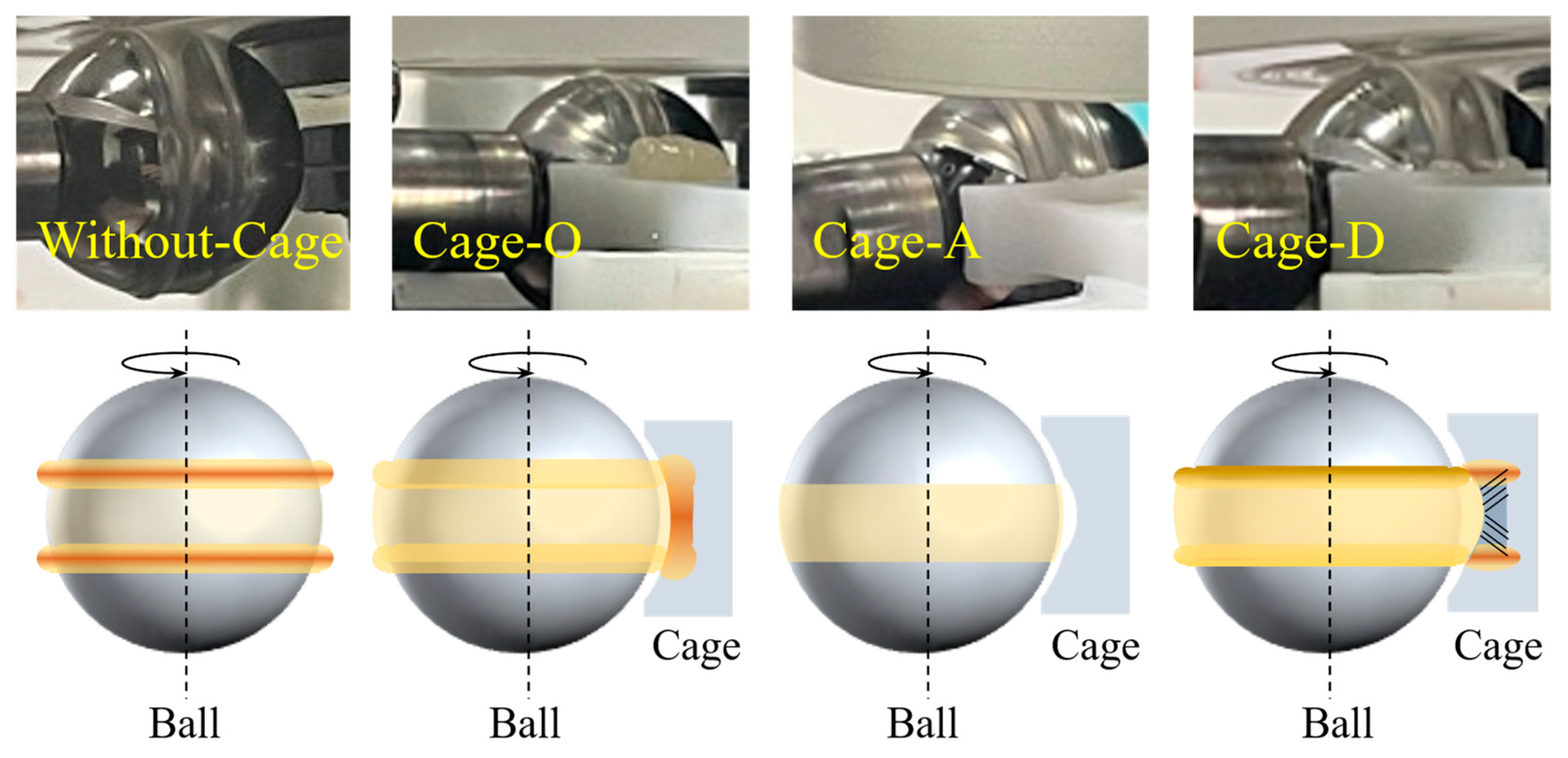
The differing lubrication behaviors in both B-D and B-C contacts can be attributed to the cage pocket shapes, which influence the flow and lubrication states in the B-C contact, as well as differences in grease distribution and replenishment [21,33]. Under starved conditions, the replenishment is primarily determined by the cage, depending on the shape and distribution of oil ridges on the cage. Figure 20 illustrates the different lubricant distribution in the B-C contact with different cage pocket shapes. Notably, a larger amount of grease accumulates in the cage pocket of the Cage-O, exhibiting a lower oil ridge, which enhances replenishment. Conversely, the decreased amount of grease in the cage pocket and the absence of a significant oil ridge in the Cage-A contact indicated insufficient lubricant reflow to the ball surface, leading to a lower film thickness compared to Cage-O, as shown in Figure 5 and Figure 7. In this lubricant distribution condition, the rapid flow of grease through the large clearance prevents its effective retained and displacement on the cage, thereby degrading lubrication performance. For Cage-D, characterized by larger oil ridges, facilitates fully flooded conditions and improves grease displacement towards the B-C contact, as depicted in Figure 18. This is primarily attributed to the induction of grease from the “unswept” area into the “swept” contact, which allows for increased lubricant amount in the B-C contact [38]. Consequently, incorporating a grooved design to induce more grease from the cage surface into the B-C contact is beneficial for improving grease flow.
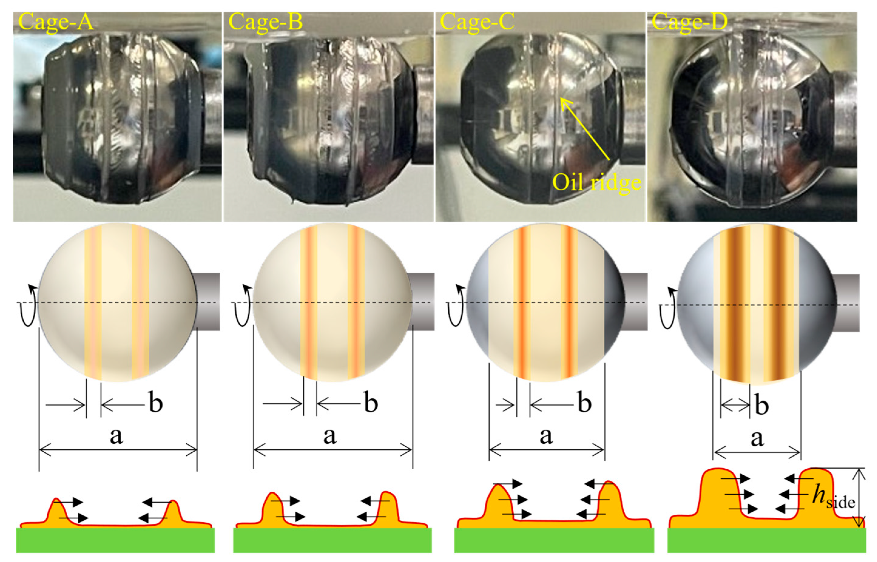
The cage facilitates grease transfer from its pockets to the ball surface, primarily determining the grease distribution and, in turn, governing replenishment efficiency and lubricating film thickness. Figure 21 shows the grease distribution on the ball surface for four tailored cage shapes with Grease C after operation at ue = 512.0 mm/s, using 1.0 g of grease. It can be observed that Cage-A exhibits a wider lubricant distribution area (distance a) and narrower oil ridges (distance b), while Cage-D shows the opposite trend: a narrower distribution area and wider oil ridges. Data presented in Figure 5, Figure 7 and Figure 9 indicate that Cage-D maintains a fully flooded lubrication condition or exhibits only slight starvation across a range of operating parameters. This is attributed to its ability to promote grease reflow into the rolling track, leading to enhanced replenishment and a thicker lubricant film. The tailored shape of Cage-D facilitates the formation of wider oil ridges or side bands on the ball surface, which are crucial for efficient grease transport. Therefore, these results provide direct evidence that tailored cage shapes can significantly improve lubrication performance by optimizing lubricant distribution on the ball surface.
The lubricant distribution on the ball surface determines the film thickness in the B-D contact and the friction in both B-C and B-D contacts. The shapes of the cage pockets impact the variations in film thickness and friction [42]. Figure 22 presents the influence of tailored cage shapes on lubrication behaviors, specifically film thickness, friction force both in B-D and B-C contacts at ue = 512.0 mm/s. As shown in Figure 22a for Grease-A, the film thickness increases from Cage-A to Cage-D, correlating with a decrease in B-D friction force and an increase in B-C friction force. A similar trend in film thickness with tailored cage shapes is observed for Greases B and C, indicating that their lubrication performance is also primarily governed by grease distribution on the ball surface, which depends on the grease flow rate driven by grease induction from the cage shoulder. Cage-A pushes more grease to the side of the rolling track, resulting in less grease on the ball surface and starvation in the B-D contact, as shown in Figure 22. This causes lower friction due to reduced viscosity and contact area in the B-C contact. Cage-B enhances grease replenishment, promoting flow and retention in the B-C contact to form side bands and flow channels. Cage-C and Cage-D exhibit an increased channel effect, resulting in thicker film thickness. Grooved surface textures on Cage-D further improve lubrication by facilitating grease migration from the cage shoulder, ensuring a consistent lubricant supply. These findings suggest that cage shapes significantly impact lubricant distribution within the bearing, influencing lubricant film formation [32,42]. Further investigation should be conducted to elucidate the underlying mechanisms governing these interactions and to optimize cage design for enhanced lubrication performance.
Friction in the B-C contact is fundamentally dependent on the film thickness. The film thickness is primarily governed by the lubricant replenishment process facilitated by the cage. This relationship can be quantified as τ = ηeff γ = ηeff (Δu/hc) = ηeff (ueξ/hc), where ηeff is the effective viscosity of the grease and hc is the central film thickness. Assuming constant values for ue and ξ, variations in effective viscosity (ηeff) arise primarily from two sources: shear within the B-C contact [33] and the thermomechanical conditions within the B-D contact. Consequently, the central film thickness (hc) depends not only on ηeff but is also heavily influenced by the degree of starvation.
To elucidate the lubrication characteristics of the ball-cage contact, with particular emphasis on frictional forces. For the friction in B-C contact can be given [41]:
F = 2 τ R d x d θ + F C
where τ is the shear stress in the B-C contact, which is given by:
τ = η u h h 2 p x
Here, R represents the radius of the steel ball and Fc is the drag contribution in the striated or cavitated regions. Based on the underlying principle from Equation (1), a reduction in the effective contact area (dx) is beneficial for decreasing the friction force within the B-C contact. The experimental results align with this principle, showing that Cage-A, which has the lowest contact area, exhibits the lowest friction. Following this, Cage-B has the second-lowest contact area and friction, while Cage-C and Cage-D have similar, larger contact areas and correspondingly higher friction.
In addition, the efficacy of lubricant replenishment from the cage governs the lubricant amount in B-C contact, which is related with Fc. This relationship is confirmed by optical imaging of the contact inlet in B-D contact. The images reveal that Cage-D, exhibiting the highest replenishment rate, maintains an abundant lubricant supply and causes a higher Fc. Conversely, Cage-A, with the lowest replenishment rate, experiences lubricant starvation, resulting in a significantly lower Fc.
The BCFL test demonstrates that a tailored cage geometry enhances lubricant film thickness and reduces friction in the B-D contact. However, the fixed B-C contact clearance, a simplification of the dynamic clearance variations in a full bearing, necessitates further validation of these designs under realistic operating conditions. Consequently, further research is required to validate the performance of these tailored cage shapes under full bearing operating conditions. Furthermore, future work should focus on the design and optimization of more advanced cage shapes, specifically to enhance lubricant replenishment, reduce friction forces, and improve fault-diagnosis capabilities for the cage [43].

5. Conclusions

This study investigated the impact of the four tailored cage shapes on lubricant mechanisms in B-D (EHL) and B-C (HL) contacts using the BCFL test. The influence of entrainment speed, base oil viscosity and grease amount on film thickness and friction force were analyzed. The present findings demonstrate the pivotal role of the cage shape in governing the lubricant distribution on the ball surface, facilitating its replenishment, and promoting the formation of an oil ridge. The following conclusions were drawn:
(1)
The cage critically modulates lubrication evolution by defining three regimes: fully flooded, slight starvation, and severe starvation. Acting as a lubricant reservoir, it governs the replenishment rate that determines starvation severity: sufficient supply sustains mild starvation, while inadequate supply accelerates severe starvation and increases friction.
(2)
In the ball-cage (B-C) contact, the cage enhances lubrication by enlarging the oil ridge, thus expanding the local lubricant reservoir and facilitating flow toward the ball-disc (B-D) contact. The coupled replenishment mechanism consistently delivers grease to the raceway, producing a thicker, more stable lubricating film and thereby reducing friction, as confirmed by BCFL measurements.
(3)
Comparative evaluation of four cage designs demonstrated that pocket geometry plays a decisive role in lubricant redistribution efficiency; the grooved design (Cage-D), in particular, effectively guided grease flow to form the widest oil ridges on the ball surface and sustained a superior lubrication regime with thicker films and lower friction levels.

Author Contributions

K.Z.: Data curation, Investigation, Writing—Original Draft. X.J.: Writing—review and editing, Supervision, Conceptualization. X.L.: Writing—review and editing. Q.B.: Writing—review and editing, Supervision. X.H.: Supervision, Data curation. H.J.: Data curation, Investigation. F.G.: Methodology, Supervision. G.Z.: Supervision, Data curation. C.L.: Data curation. J.L.: Data curation. All authors have read and agreed to the published version of the manuscript.

Funding

This research was funded by Natural Science Foundation of China (Project No. 52275196 and 52205201).

Data Availability Statement

The original contributions presented in this study are included in the article. Further inquiries can be directed to the corresponding authors.

Conflicts of Interest

Authors Xuyang Jin, Xinming Li, Guohui Zhang were employed by the company Puyang Xinye Special Lubricating Oil and Grease Co., Ltd. and Xiongrong Huang was employed by Shanghai Bearing Technology Research Institute Co., Ltd. The remaining authors declare that the research was conducted in the absence of any commercial or financial relationships that could be construed as a potential conflict of interest.

References

  1. Holmberg, K.; Erdemir, A. Influence of tribology on global energy consumption, costs and emissions. Friction 2017, 5, 263–284. [Google Scholar] [CrossRef]
  2. Zhou, Y.Q.; Peng, X.; Chen, Y. An approach for predicting the vibro-impact behavior of angular contact ball bearing considering variable clearance. Lubricants 2025, 13, 216. [Google Scholar] [CrossRef]
  3. Cojocaru, D.; Ianuș, G.; Cârlescu, V.; Chiriac, B.; Olaru, D. Grease Film Behavior in Ball Bearings. Lubricants 2025, 13, 429. [Google Scholar] [CrossRef]
  4. Yu, C.; Cheng, R.; Zhang, H.; Ma, C.; Yu, S. The Influences of Surface Texture Topography and Orientation on Point-Contact Mixed Lubrication. Lubricants 2025, 13, 409. [Google Scholar] [CrossRef]
  5. Pei, X. Scale Effects of Surface-Texture Distribution on Lubrication and Friction. Tribol. Lett. 2025, 73, 86. [Google Scholar] [CrossRef]
  6. Yue, L.; Cao, H.; Meng, Y.; Wei, P.; Zhao, H.; Xu, W.; Bai, P.P.; Meng, Y.G.; Tian, Y. Frictional mechanisms of a novel base lubricant material: Optimizing tribological performance through viscosity-wear design. Friction 2025, accepted. [Google Scholar] [CrossRef]
  7. Gu, T.; Jane Wang, Q.; Xiong, S.; Liu, Z.; Gangopadhyay, A.; Liu, Z. Profile design for misaligned journal bearings subjected to transient mixed lubrication. J. Tribol. 2019, 141, 071701. [Google Scholar] [CrossRef]
  8. Sperka, P.; Krupka, I.; Hartl, M. Lubricant flow in thin-film elastohydrodynamic contact under extreme conditions. Friction 2016, 4, 380–390. [Google Scholar] [CrossRef]
  9. Okal, M.; Kostal, D.; Sperka, P.; Krupka, I.; Hartl, M. Effect of contact conformity on grease lubrication. Lubricants 2022, 10, 289. [Google Scholar] [CrossRef]
  10. Qiang, H.; Anling, L.; Yangming, Z.; Liu, S.; Yachen, G. Experimental study of tribological properties of lithium-based grease with Cu nanoparticle additive. Tribol.-Mater. Surf. Interfaces 2017, 11, 75–82. [Google Scholar] [CrossRef]
  11. Wen, C.W.; Meng, X.H.; Gu, J.M.; Xiao, L.; Jiang, S.; Bi, H.B. Starved lubrication analysis of angular contact ball bearing based on a multi-degree-of-freedom tribo-dynamic model. Friction 2023, 11, 1395–1418. [Google Scholar] [CrossRef]
  12. Liu, Y.Q.; Chen, Z.G.; Tang, L.; Zhai, W.M. Skidding dynamic performance of rolling bearing with cage flexibility under accelerating conditions. Mech. Syst. Signal Process. 2021, 150, 107257. [Google Scholar] [CrossRef]
  13. Su, B.; Li, H.; Zhang, G.T.; Liu, F.B.; Cui, Y.C. Study on cage stability of solid-lubricated angular contact ball bearings in an ultra-low temperature environment. Lubricants 2024, 12, 124. [Google Scholar] [CrossRef]
  14. Guerzoni, F. Lubricants’ role in blade performance. Renew. Energy Focus 2014, 15, 28–29. [Google Scholar] [CrossRef]
  15. Zhang, Y.F.; Fang, B.; Kong, L.F.; Li, Y. Effect of the ring misalignment on the service characteristics of ball bearing and rotor system. Mech. Mach. Theory 2020, 151, 103889. [Google Scholar] [CrossRef]
  16. Chen, H.B.; Liang, H.; Wang, W.Z.; Zhang, S.G. Investigation on the oil transfer behaviors and the air-oil interfacial flow patterns in a ball bearing under different capillary conditions. Friction 2023, 11, 228–245. [Google Scholar] [CrossRef]
  17. Gao, S.; Han, Q.H.; Pennacchi, P.; Chatterton, S.; Chu, F.L. Dynamic, thermal, and vibrational analysis of ball bearings with over-skidding behavior. Friction 2022, 11, 580–601. [Google Scholar] [CrossRef]
  18. Sadeghi, F.; Arya, U.; Aamer, S.; Meinel, A. A review of computational fluid dynamics approaches used to investigate lubrication of rolling element bearings. J. Tribol. 2024, 146, 100801. [Google Scholar] [CrossRef]
  19. Wang, P.F.; Yang, Y.; Ma, H.; Xu, H.Y.; Li, X.; Luo, Z.; Wen, B.C. Vibration characteristics of rotor-bearing system with angular misalignment and cage fracture: Simulation and experiment. Mech. Syst. Signal Process. 2023, 182, 109545. [Google Scholar] [CrossRef]
  20. You, J.Y.; Ma, X.Q.; Liu, C.Y.; Zuo, M.J.; Jin, D.L.; Zhang, H. Measurement and dynamic analysis of the centroid trajectories of angular-contact ball bearing cages. Lubricants 2024, 12, 379. [Google Scholar] [CrossRef]
  21. Yang, Y.; Qi, X.Y.; Wang, Y.J.; Wang, M.L.; Wen, B.G.; Zhai, J.Y. Dynamic characteristics of a cylindrical roller bearing with cage cracks. Lubricants 2025, 13, 25. [Google Scholar] [CrossRef]
  22. Yuan, D.; Wang, R.; Chen, S.; Chen, X. Experimental research on cage motion with different pocket shapes in angular contact ball bearing. Proc. Inst. Mech. Eng. Part J J. Eng. Tribol. 2022, 236, 1325–1335. [Google Scholar] [CrossRef]
  23. Zhang, G.; Shi, Y.; Li, C.; Xu, M.; Yin, Y. Unsteady seepage behavior of lubricant on loaded porous surface. Phys. Fluids 2022, 34, 072110. [Google Scholar] [CrossRef]
  24. Chen, W.; Wang, W.; Liang, H.; Zhu, P. Study on lubricant release-recycle performance of porous polyimide retainer materials. Langmuir 2022, 38, 11440–11450. [Google Scholar] [CrossRef]
  25. Zhao, H.; Prieto- López, L.O.; Zhou, X.; Deng, X.; Cui, J. Multistimuli responsive liquid-release in dynamic polymer coatings for controlling surface slipperiness and optical performance. Adv. Mater. Interfaces 2019, 6, 1901028. [Google Scholar] [CrossRef]
  26. Zhang, D.; Wang, T.M.; Wang, Q.H.; Wang, C. Selectively enhanced oil retention of porous polyimide bearing materials by direct chemical modification. J. Appl. Polym. Sci. 2017, 134, 45106. [Google Scholar] [CrossRef]
  27. Maccioni, L.; Chernoray, V.G.; Concli, F. Investigating lubricant behavior in a partially flooded tapered roller bearing: Validation of a multiphase CFD solver for aerated oil sump via particle image velocimetry studies and high-speed camera acquisitions. Tribol. Int. 2025, 201, 110274. [Google Scholar] [CrossRef]
  28. Li, J.B.; Liu, J.Y.; Li, K.; Zhou, N.N.; Liu, Y.; Hu, X.D.; Yin, S.L.; Wang, G.R. Tribological properties of oil-impregnated polyimide in double-contact friction under micro-oil lubrication conditions. Friction 2023, 11, 1493–1504. [Google Scholar] [CrossRef]
  29. Russell, T.; Sadeghi, F.; Peterson, W.; Aamer, S.; Arya, U. A novel test rig for the investigation of ball bearing cage friction. Tribol. Trans. 2021, 64, 943–955. [Google Scholar] [CrossRef]
  30. Liang, H.; Zhang, Y.; Wang, W.Z. Influence of the cage on the migration and distribution of lubricating oil inside a ball bearing. Friction 2021, 10, 1035–1045. [Google Scholar] [CrossRef]
  31. Damiens, B.; Lubrecht, A.; Cann, P.M. Influence of cage clearance on bearing lubrication. Tribol. Trans. 2004, 47, 2–6. [Google Scholar] [CrossRef]
  32. Jin, X.Y.; Li, X.M.; Liu, Y.; Gao, J.B.; Bai, L.Q. Experimental study of lubricant distribution and lubrication enhancement induced by ball bearing cage. J. Tribol. 2024, 146, 074103. [Google Scholar] [CrossRef]
  33. Jin, X.Y.; Wang, Y.H.; Bai, Q.H.; Li, X.M.; Jiang, H.; Guo, F.; Bai, X.Y.; Poll, G. Cage parameters on friction within cage-pockets contacts and lubrication behaviors in ball-raceway contacts. Tribol. Int. 2025, 209, 110747. [Google Scholar] [CrossRef]
  34. Liu, H.C.; Guo, F.; Guo, L.; Wong, P.L. A dichromatic interference intensity modulation approach to measurement of lubricating film thickness. Tribol. Lett. 2015, 58, 15–25. [Google Scholar] [CrossRef]
  35. Li, X.M.; Guo, F.; Poll, G.; Fei, Y.; Yang, P. Grease film evolution in rolling elastohydrodynamic lubrication contacts. Friction 2021, 9, 179–190. [Google Scholar] [CrossRef]
  36. Gershuni, L.; Larson, M.G.; Lugt, P.M. Lubricant replenishment in rolling bearing contact. Tribol. Trans. 2008, 51, 643–651. [Google Scholar] [CrossRef]
  37. Molina, M.; Gohar, R. Hydrodynamic lubrication of ball-bearing cage pockets. Arch. J. Mech. Eng. Sci. 1978, 20, 11–20. [Google Scholar] [CrossRef]
  38. Sathwik, C.K.R.; Osara, J.A.; Lugt, P.M. Impact of grease churning on grease leakage, oil bleeding, and grease rheology. Tribol. Int. 2022, 176, 107926. [Google Scholar] [CrossRef]
  39. Wedeven, L.; Evans, D.; Cameron, A. Optical analysis of ball bearing starvation. J. Tribol. 1971, 93, 349–361. [Google Scholar] [CrossRef]
  40. Chiu, Y. An analysis and prediction of lubricant film starvation in rolling contact systems. ASLE Trans. 1973, 17, 22–35. [Google Scholar] [CrossRef]
  41. Molina, M.; Gohar, R. Hydrodynamic design of ball bearing cage pockets. Tribol. Int. 1979, 12, 15–20. [Google Scholar] [CrossRef]
  42. Russell, T.; Sadeghi, F.; Kang, Y.S.; Mazzitelli, I. The influence of cage pocket lubrication on the simulation of deep groove ball bearing cage motion. J. Tribol. 2024, 146, 022201. [Google Scholar] [CrossRef]
  43. Shao, X.Y.; Cai, B.P.; Zou, Z.X.; Shao, H.D.; Yang, C.; Liu, Y.H. Artificial intelligence enhanced fault prediction with industrial incomplete information. Mech. Syst. Signal Process. 2025, 224, 112063. [Google Scholar] [CrossRef]
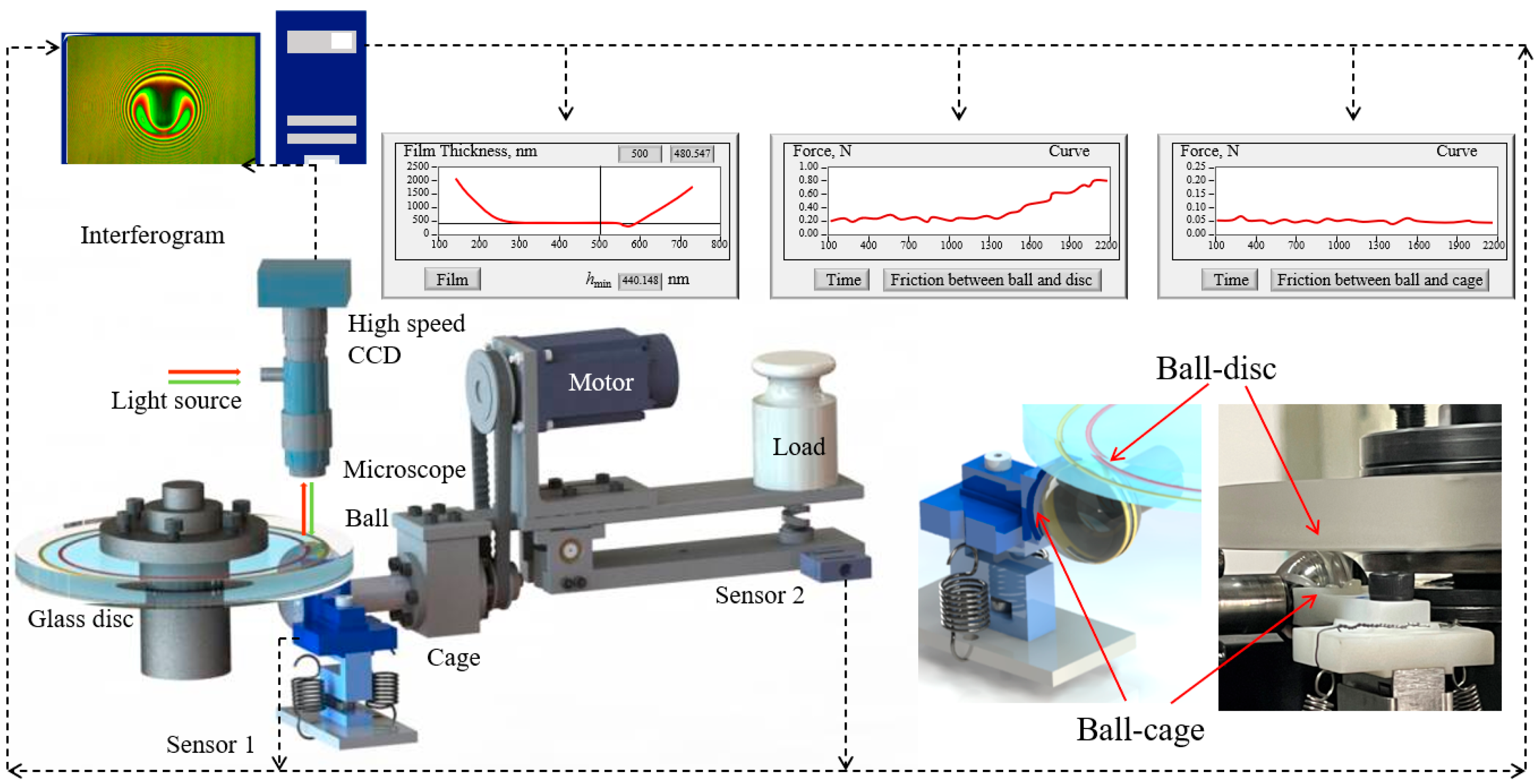
Figure 1. Structure of apparatus and measurement scheme.
Lubricants 13 00501 g001
Figure 2. Grease loss modulus, storage modulus and shear stress used in the experiment.
Lubricants 13 00501 g002
Figure 3. The grease distribution under the effect of cage.
Lubricants 13 00501 g003
Figure 4. Schematic of cage types.
Lubricants 13 00501 g004
Figure 5. Evolution of EHL films against time with the different cage shapes and without cage, ue = 64.0 mm/s, Grease-B. (a) Interference images; (b) Variations in film thickness over time.
Lubricants 13 00501 g005
Figure 6. Friction forces against time with the different cage shapes and without a cage, ue = 64.0 mm/s, Grease-B. (a) Friction force in ball-disc contacts over time; (b) Friction force in ball-cage contacts over time.
Lubricants 13 00501 g006
Figure 7. Evolution of EHL films against time with the different cage shapes and without cage, ue = 256.0 mm/s, Grease-B. (a) Interference images; (b) Variations in film thickness over time.
Lubricants 13 00501 g007aLubricants 13 00501 g007b
Figure 8. Friction forces against time with the different cage shapes and without a cage, ue = 256.0 mm/s, Grease-B. (a) Friction force in ball-disc contacts over time; (b) Friction force in ball-cage contacts over time.
Lubricants 13 00501 g008aLubricants 13 00501 g008b
Figure 9. Evolution of EHL films against time with the different cage shapes and without a cage, ue = 512.0 mm/s, Grease-B. (a) Interference images; (b) Variations in film thickness over time.
Lubricants 13 00501 g009aLubricants 13 00501 g009b
Figure 10. Friction forces against time with the different cage shapes and without a cage, ue = 512.0 mm/s, Grease-B. (a) Friction force in ball-disc contacts over time; (b) Friction force in ball-cage contacts over time.
Lubricants 13 00501 g010aLubricants 13 00501 g010b
Figure 11. Evolution of EHL films against time with the different cage shapes, ue = 512.0 mm/s, Grease-A. (a) Interference images; (b) Variations in film thickness over time.
Lubricants 13 00501 g011
Figure 12. Friction forces against time with the different cage shapes, ue = 512.0 mm/s, Grease-A. (a) Friction force in ball-disc contacts over time; (b) Friction force in ball-cage contacts over time.
Lubricants 13 00501 g012
Figure 13. Evolution of EHL films against time with the different cage shapes, ue = 512.0 mm/s, Grease-C. (a) Interference images; (b) Variations in film thickness over time.
Lubricants 13 00501 g013
Figure 14. Friction forces against time with the different cage shapes, ue = 512.0 mm/s, Grease-C. (a) Friction force in ball-disc contacts over time; (b) Friction force in ball-cage contacts over time.
Lubricants 13 00501 g014
Figure 15. Evolution of EHL films against time with the different cage shapes, ue = 512.0 mm/s, Grease-C, 1.0 g. (a) Interference images; (b) Variations in film thickness over time.
Lubricants 13 00501 g015
Figure 16. Friction forces against time with the different cage shapes, ue = 512.0 mm/s, Grease-C, 1.0 g. (a) Friction force in ball-disc contacts over time; (b) Friction force in ball-cage contacts over time.
Lubricants 13 00501 g016
Figure 17. Schematic diagram of lubricant distribution mechanism under the effect of cage. (a) three lubrication states; (b) master curve for different cage types.
Lubricants 13 00501 g017
Figure 18. Comparison of lubricant distribution and replenishment sources with and without a cage.
Lubricants 13 00501 g018
Figure 19. The lubricant migration and distribution mechanism under the effect of cage.
Lubricants 13 00501 g019
Figure 20. Observed effects of different cage types on lubricant distribution on the ball surface and the cage.
Lubricants 13 00501 g020
Figure 21. Comparison of lubricant distribution on the ball surface for different cage types.
Lubricants 13 00501 g021
Figure 22. Comparison of film thickness and friction forces for different grease types and cage shapes. (a) Grease-A; (b) Grease-B; (c) Grease-C.
Lubricants 13 00501 g022
Table 1. Properties of test greases.
Grease SamplesViscosity of Base Oil (mm2/s)Cone Penetration
(0.1 mm)
Grease A66 ± 0.66281 ± 1
Grease B614 ± 6.14293 ± 1
Grease C1240 ± 12.4284 ± 1
Table 2. Test conditions.
ParameterValues
Entrainment speed (mm/s), ue64.0 ± 0.5, 256.0 ± 0.5, 512.0 ± 0.5
Load (N)30.0
SRR0.05
Ball diameter, (mm) 25.4
Ball surface roughness (Ra), nm14 ± 1
Disc diameter, (mm)150
Disc surface roughness (Ra), nm20 ± 1
Grease amount (g)
Temperature (°C)
2.0, 1.0
22.0 ± 1
Grease typesG-A, G-B, G-C
X axis-clearance (mm)0.2
Y axis-height (mm)0.0
Cage type
Cage pocket radius (mm)
Cage-A, Cage-B Cage-C Cage-D
13.7
Cage height (mm)8.47
Table 3. The disc and ball speeds at different entrainment speeds, ξ = 0.05.
ue, mm/s64.0 ± 0.5256.0 ± 0.5512.0 ± 0.5
ud, mm/s65.6 ± 0.5262.4 ± 0.5524.8 ± 0.5
ub, mm/s62.4 ± 0.5249.6 ± 0.5499.2 ± 0.5
Disclaimer/Publisher’s Note: The statements, opinions and data contained in all publications are solely those of the individual author(s) and contributor(s) and not of MDPI and/or the editor(s). MDPI and/or the editor(s) disclaim responsibility for any injury to people or property resulting from any ideas, methods, instructions or products referred to in the content.