Article

Fretting Friction and Wear Characteristics of the Internal Spiral Contact Steel Wires in the Hoisting Wire Rope Under Different Service Conditions

1
National Key Laboratory of Intelligent Mining Equipment Technology, School of Mechanical and Electrical Engineering, China University of Mining and Technology, Xuzhou 221116, China
2
Key Laboratory of Intelligent Operation and Maintenance of High-Parameter Lifts, State Administration for Market Regulation, Suzhou 215031, China
3
Jiangsu Special Equipment Safety Supervision and Inspection Institute, Nanjing 210036, China
*
Author to whom correspondence should be addressed.
Lubricants 2025, 13(10), 453; https://doi.org/10.3390/lubricants13100453
Submission received: 16 September 2025 / Revised: 8 October 2025 / Accepted: 14 October 2025 / Published: 17 October 2025
(This article belongs to the Special Issue Tribological Behavior of Wire Rope)

Abstract

As a critical load-bearing component in mine hoisting systems, the service performance and lifespan of wire ropes are limited by the fretting wear behavior among their internal wires and strands. To investigate the effect of fretting parameters on the wear mechanisms in wire ropes, this paper systematically conducts fretting wear experiments on multi-wire contact pairs under varying fretting frequencies and tensile loads. The results show that as the fretting frequency increases from 0.5 Hz to 3.0 Hz, the coefficient of friction (COF) rises, with its steady-state value reaching approximately 0.65. Conversely, as the tension decreases from 150 N to 90 N, the COF increases, attaining a steady-state value of 0.71. The slip regime between the steel wires evolves from gross slip to partial slip with increasing frequency. With an increase in tensile load, the slip regime transitions from gross slip to partial slip and finally to adhesion. Higher fretting frequencies and greater tensile loads exacerbate both the wear rate and the severity of damage on the spiral contact wires inside the hoisting rope. The highest wear rate, 27.2 × 10⁻⁶ mm3/N·m, is observed at 3.0 Hz, while the maximum wear rate under tension is 39.6 × 10⁻⁶ mm3/N·m at 150 N. The dominant wear mechanisms at higher frequencies are abrasive wear, tribochemical reaction, and surface fatigue. Under greater tension, the primary wear mechanisms are abrasive wear, surface fatigue, and tribochemical reaction.

1. Introduction

Hoisting rope is the “lifeline” of the mine, which is responsible for lifting and lowering personnel, coal, equipment, and so on under extremely harsh conditions [1]. The wire rope consists of core strand and multiple strand ropes, each of which is itself composed of numerous steel wires, as shown in Figure 1a. The complex spatial spiral structure gives the hoisting rope excellent flexibility and bearing capacity but also produces a large number of internal contact wire contacts, as shown in Figure 1b. During the hoisting process, the tension fluctuation of the wire rope can cause extrusion, torsion and relative displacement between the internal wires, which will cause fretting wear between the wires and reduce the mechanical properties of the hoisting rope [2,3]. Moreover, due to the complex service conditions of the mine hoisting wire rope, different fretting frequencies and tension levels will affect the friction and wear behavior between the wires in wire rope, which affects the service performance of the hoisting rope [4]. Therefore, investigating the fretting wear of spiral contact steel wire inside the mine hoisting rope under different service conditions (fretting frequency and tension) can provide a theoretical foundation for safe and efficient operation of the mine hoisting, and provide a data basis for the service life prediction of the hoisting rope.
The hoisting rope is continuously deteriorated under the action of various factors such as wear, corrosion, tension, fatigue and bending [5]. Among them, wear is the main reason for the decrease in strength and service life of steel wire rope. Based on the semi-analytical method, Chen et al. [6,7] established a solution model for the evolution of wear, taking into account the influence of wear damage on the contact behavior of the rope strands. Hu et al. [8] calculated the micro-movement parameters of the steel wire in typical contact areas and used the finite element method to simulate the wear evolution process under tensile loads under different stress ratios. Urchegui et al. [9] proposed a method for measuring the depth of wear marks and the volume of wear on worn steel wires. Zhang et al. [10,11] established a wear test system for hoisting rope under vibration conditions and explored the damage evolution law under different vibration frequencies and vibration amplitudes. Furthermore, considering the influence of temperature, Peng et al. [12] and Ma et al. [13] investigated the effect on different service temperatures on the sliding wear of wire rope. Fretting wear between internal steel wires is a key factor for the decrease in service performance of hoisting rope. Experimental investigations by Harris et al. [14,15] revealed that wear loss in steel wires is significantly influenced by contact stress, and they identified both wear and bending stress as the primary factors leading to crack initiation. Cruzado et al. [16,17,18,19,20] explored the COF and wear rate of fine steel wire under different contact stress and cross angle conditions under laboratory conditions and verified the wear evolution process by finite element simulation. Zhang et al. [21,22,23] used 2–3 steel wires to simulate the contact between internal steel wires, explored the fretting behavior under different strain ratios and crossing angles, and further explored the crack propagation behavior of steel wires after fretting damage. Furthermore, Wang et al. [24,25] conducted friction and wear tests between steel wires under different contact conditions based on the calculation of the internal tensile force, relative slip and contact force of the steel wire rope and explored the crack initiation and propagation mechanism of the steel wires. Considering the failure problem caused by the decrease in the strength of the hoisting rope, Torkar et al. [26] investigated the failure causes of multi-strand steel wire ropes for lifting purposes and found that there were numerous decarburization cracks on the surface of the broken wire ropes, with decarburization cracks being the initiation points of fatigue crack propagation. Moradi et al. [27] studied the failure of multi-strand steel wire ropes used in drilling rig hooks through metallographic examination and finite element analysis and concluded that excessive loading-induced high tensile stress and large bending curvature were the main reasons for the failure and damage of the wire ropes. Lin et al. [28] explored the strength degradation behavior of steel wire rope under the interactive effect of corrosion and wear. Shi et al. [29] carried out tensile, torsion and bending strength tests on old and new steel wire ropes and rusted steel wire ropes and studied the loss of tensile strength and toughness of steel wire ropes. In addition, Vukelic et al. [30] simulated the progressive damage process of steel wire ropes by changing the cross-sectional area of steel wire ropes to numerically predict the corresponding stress level and residual fatigue life. Tijani et al. [31] evaluated the impact of steel wire rope degradation based on accelerated corrosion and mechanical damage caused by broken steel wires, using a damage model that takes into account resistance loss. To more accurately assess the safety of the steel wire rope, Slesarev et al. [32] proposed a method for determining probability characteristics, which is used to detect existing damages in heterogeneous steel wire rope structures. In the existing research, the main research is the sliding wear between the wire ropes and the use of 2–3 steel wires to simulate the contact between wires in wire rope. The service conditions of the wire rope are complex and changeable, and the fretting frequency and wire tension conditions between internal spiral wires will affect the fretting damage behavior between the wires.
Therefore, this study aims to explore the fretting wear behavior of spiral contact wires under different service conditions. The fretting wear behavior under different fretting frequencies and different wire tensions were compared and analyzed by a fretting friction and wear test apparatus. The COF under different service conditions was obtained, and the wear parameters and microstructure of the test wires were measured by confocal profilometer, digital microscope and scanning microscope. This paper is to reveal the fretting wear evolution law of spiral contact wires under different service conditions, which is important to grasp the relationship between the service condition parameters and the friction damage of steel wire, so as to realize the safety and reliable operation of mine hoisting rope.

2. Materials and Methods

2.1. Materials

In this study, steel wire used to manufacture 18 × 7 + IWS wire rope were chosen as the test object. The wires were new carbon steel wires that had undergone cold drawing. Each group of test samples was six 1 mm side wires and one 1.1 mm core wire. The selection standard of steel wire conforms to the national standard GB/T33955-2017 [33] of the People’s Republic of China for mine hoisting wire rope. The physical properties and chemical composition of the steel wire are shown in Table 1 and Table 2. Before the start of the test, the steel wire was wiped with alcohol to remove the surface rust-proof oil and pollutants.

2.2. Testing Apparatus and Procedures

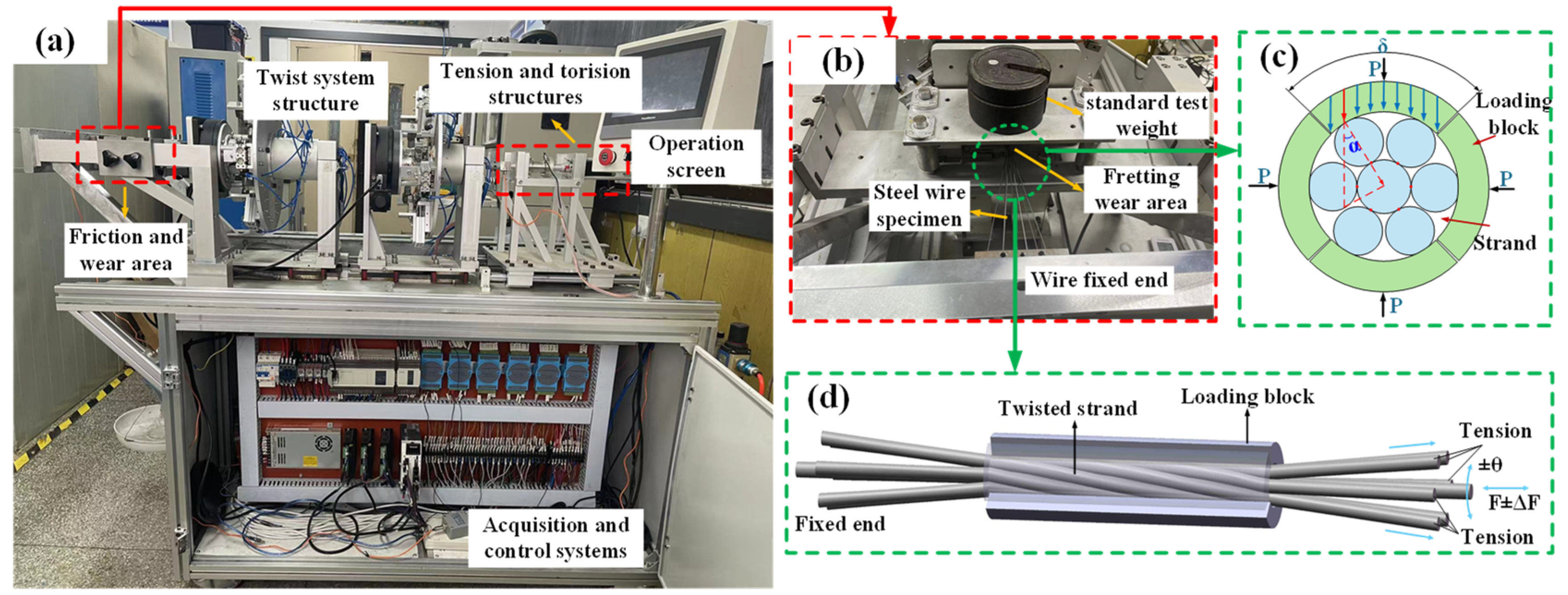
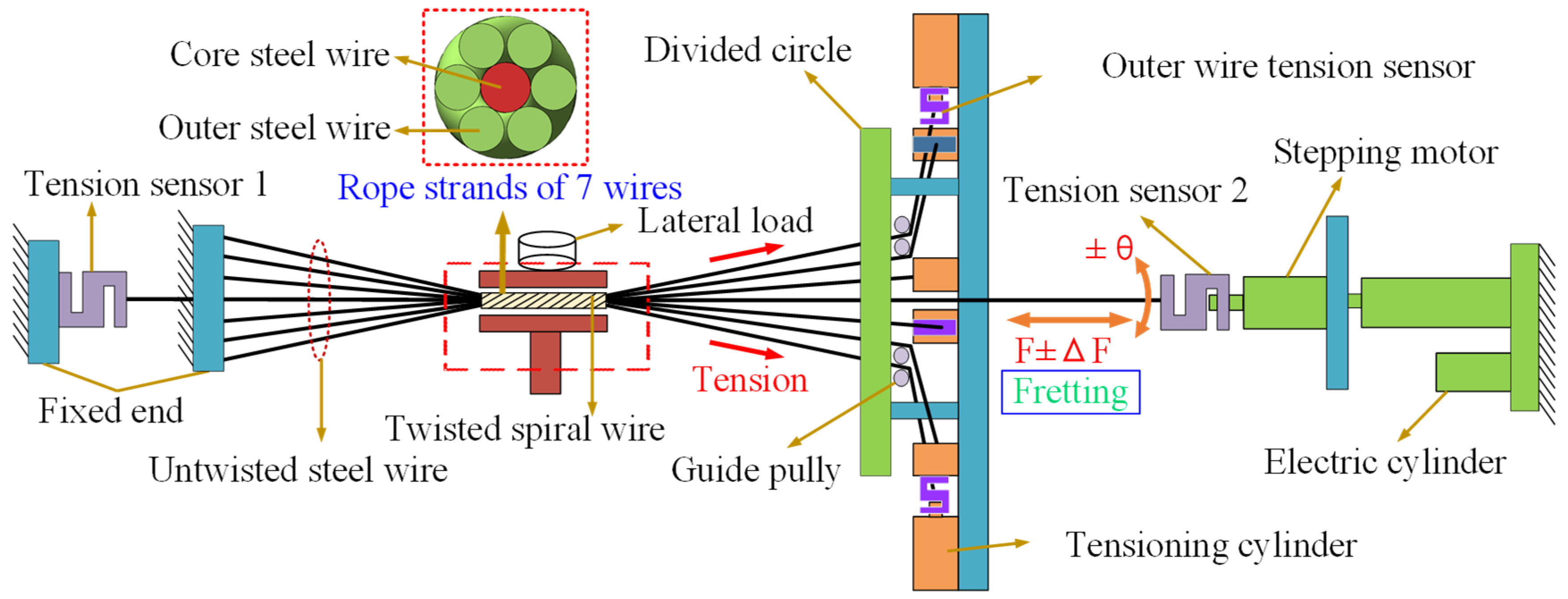
The fretting friction and wear behavior of spiral contact steel wire under different service conditions was studied by using the self-developed multi-wire spiral contact fretting friction and wear test apparatus. Figure 2 and Figure 3 are the overall structure diagram and working principal diagram of the fretting test apparatus, respectively. The apparatus mainly comprises the following parts: the core wire tension–torsion structure, twisting and tensioning structure of outer steel wire, the lateral force loading structure and the data acquisition system.
The test apparatus fixes one end of each steel wire through a steel wire fixing plate. The other end of the core wire is clamped by the center wire fixed end fixture. The electric cylinder can slide along a linear guide rail, thereby providing tension for the core wire and achieving fretting slip, while the torsion of core wire is controlled by the stepper motor. Six loading cylinders are evenly arranged on the turntable along the circumference. One end of the six side wires is fastened to the corresponding cylinder, and the other end is fixed to the side wire fixing block through the guide wheel. The electric dividing disk drives the rotating disk through the connecting rod, so that six side wires are twisted around the core wire with set parameters to form a strand structure. A closed-loop control system is implemented to precisely regulate the tension of the side wire. This system comprises three key components: a tension sensor, a controller and an air cylinder. The operational workflow is as follows: The tension sensor continuously monitors the actual tension value in the side wire and sends this data to the controller. The controller compares the measured tension with a predefined target value. If a discrepancy (error) is detected, the controller calculates and sends a command signal to the air cylinder. Accordingly, the air cylinder extends or retracts to adjust the wire tension, thereby minimizing the error and maintaining the tension at the desired level. This feedback loop ensures stable and accurate tension control throughout the operation. The transverse force loading is used to apply transverse load to the twisted wire rope strand to simulate the extrusion effect of outer steel wire or side strand on the rope strand in actual service conditions. Compared with professional twisting equipment, the test device has the functions of independent control of tension and torsion of each wire, data acquisition, reciprocating micro-motion and lateral loading. The design of the test device refers to the mechanical industry standard JB/T11174-2011 [34] of the People ‘s Republic of China.
To simulate actual working conditions, the twisting parameters of rope strands in the test are consistent with the actual wire rope structure parameters. In the process of mine hoisting, wire rope can be affected by many factors such as tension fluctuation, load change, hoisting speed and vibration, which leads to the dynamic change in its loading, displacement amplitude, torsion angle and fretting frequency [4]. The fretting parameters used in this test are selected according to the above actual working conditions. The specific test parameters are shown in Table 3.

2.3. Analysis Method

To facilitate the analysis under the same standard [35], this study defines the fretting state according to the fretting parameters. In this test, the semi-major axis of the nominal contact ellipse between the steel wires is 16.8 mm, which is much larger than the fretting amplitude of 400 μm, so it can be judged that the test is in the fretting range.
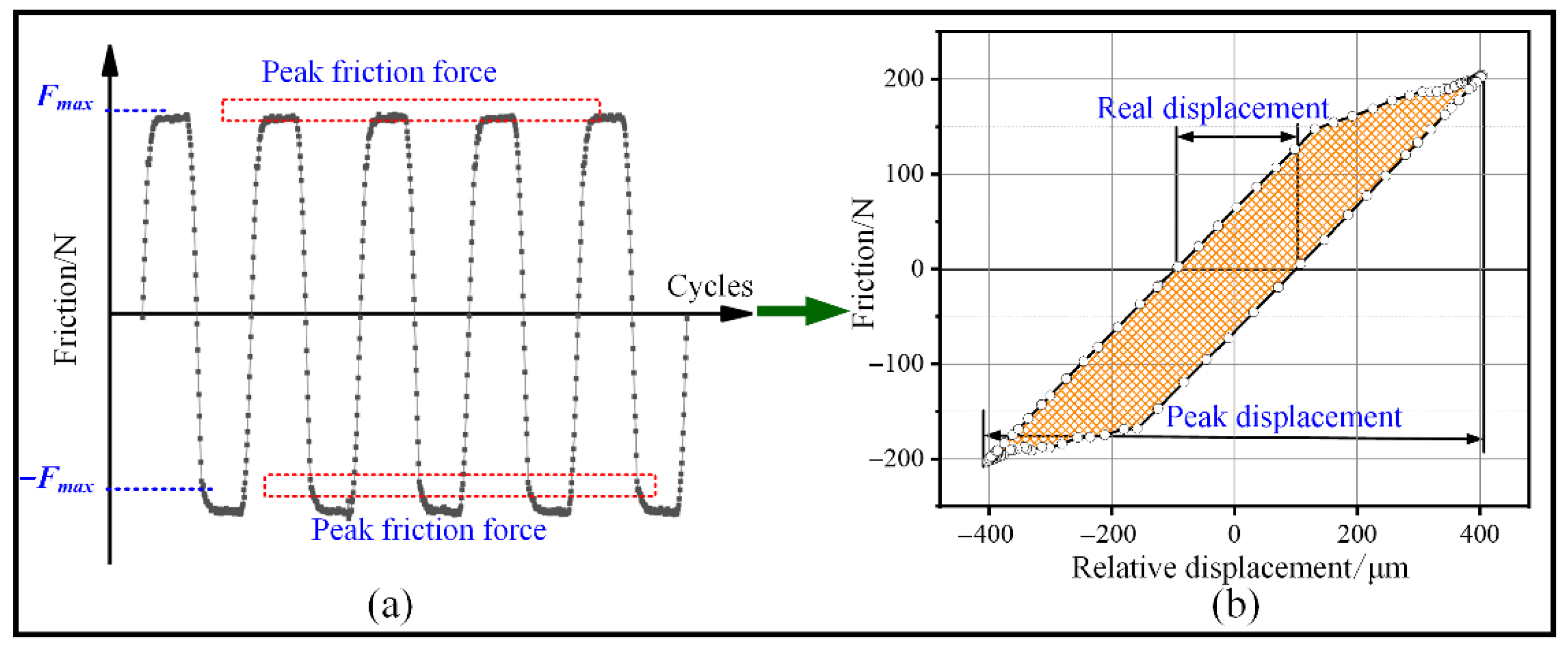
COF is one of the key parameters to study the fretting friction and wear behavior between spiral contact steel wires. By obtaining the contact pressure and friction data between the steel wires, the COF between the core wire and side wires can be calculated. Among them, the contact pressure value is determined by force analysis, as shown in Figure 2c. The friction of the core wire is obtained by the difference between the tension sensors. Figure 4a shows friction curves in several cycles. The COF can be calculated by Equations (1)–(3) [35]:
F n = 4 0 δ P δ c o s α d α
  F a v = i = 1 k F f i m
f a v = ( F a v m a x F a v m i n ) 2 · F n F l m a x ( F m a x F l m a x )
where δ is the coating angle of the loading block in °, α is the angle between the load per unit length and the center of the rope strand in °, Fav is the average friction force of a single cycle in N, Ffi is the friction force value of a single point acquisition in N, m is the number of acquisition points in a cycle, fav is the COF of a single cycle, Fn is the normal load in N, Favmax is the average friction force of the push stroke in N, Favmin is the average friction force of the return stroke in N, Flmax is the peak friction force when no transverse load is applied in N, and Fmax is the peak friction force when transverse load is applied in N.
During the fretting process, steel wire exhibits obvious hysteresis characteristics. According to the measured friction and slip data, the corresponding hysteresis curve can be drawn, as shown in Figure 4b. The slip is calculated by loading force and steel wire material properties. According to the different fretting states, the hysteresis curves have three typical types: gross slip state corresponds to the parallelogram, the partial slip state presents a quasi-parallelogram and the adhesion state is linear [23].
After the fretting fatigue test, the wear parameters including wear depth, wear volume and wear rate are analyzed. As shown in Figure 5a, the wear surface of the steel wire is measured by the non-contact measurement method of the confocal laser scanning microscope (SM-1000, Sixian Optoelectronic Technology Co., LTD, Shanghai, China), and the wear characteristic parameters of the steel wire are extracted by the post-processing software. In addition, the wear rate can be obtained by the amount of wear and slip. It can be expressed as Equation (4) [35]:
k = W v 2 · X r e a l · n · F n
where Wv is the total wear volume in μm3, and k is the wear rate in mm3/(N·m).
Furthermore, the microscopic surface morphology of worn samples was obtained using a scanning electron microscope (Sigma 300, ZEISS, Oberkochen, Germany) and a digital optical microscope (DSX1000, OLYMPUS, Tokyo, Japan) (in Figure 5b).

3. Results

3.1. COF

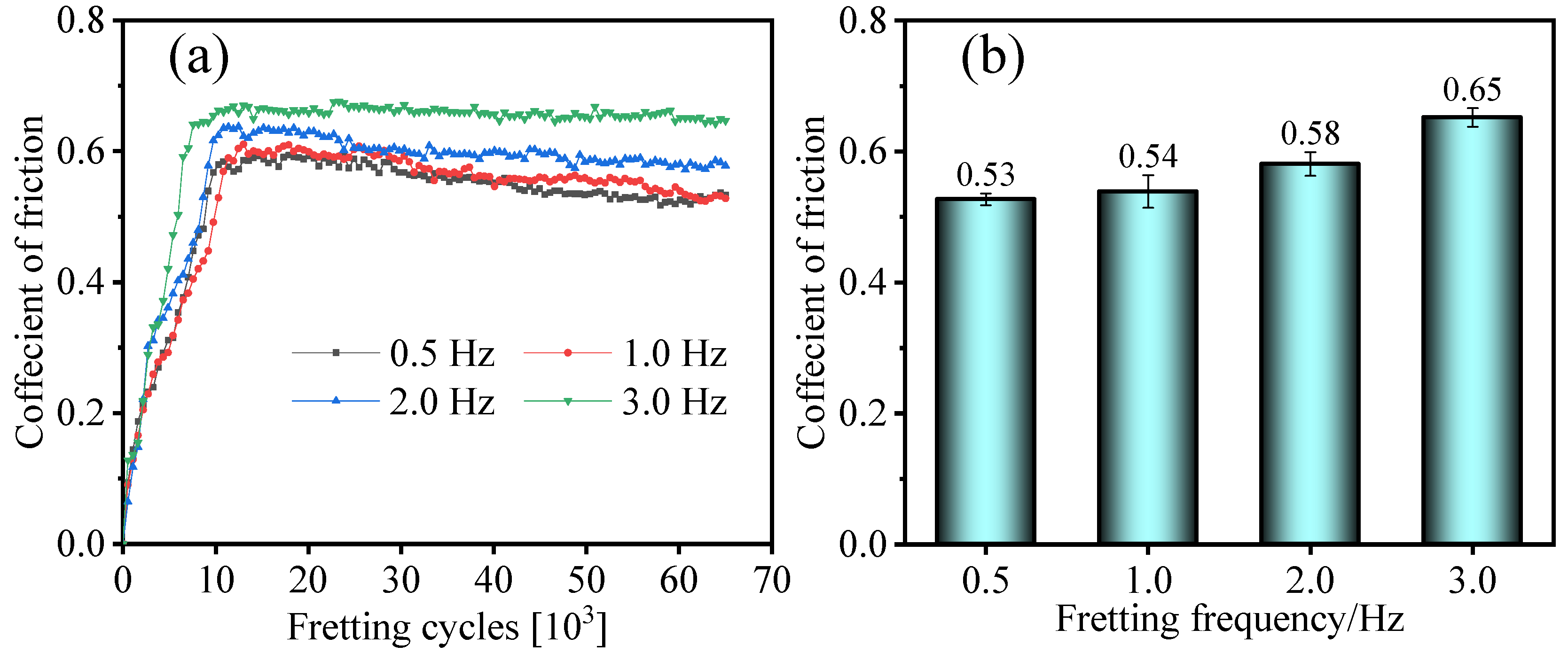
Figure 6 shows the evolution of the COF and its steady-state values at different fretting frequencies. The evolution trend under different fretting speeds was consistent: first, it rises rapidly, then enters the stable stage. It was observed that the COF of the wires with low fretting frequency needed more cycles to enter the stable wear stage at the beginning stage, which is due to the faster reciprocating speed of the steel wire with high fretting frequency. The higher speed caused the instantaneous high temperature on the surface of the steel wire and accelerated the damage of the contact surface. As shown in Figure 6b, the COF of steel wire at 0.5 Hz fretting frequency is 0.53, and the COF at 3.0 Hz fretting frequency is 0.65. Obviously, the steady-state value with higher fretting frequency is higher. This is due to the instantaneous high temperature between the steel wires caused by the high fretting frequency, which causes the local plastic deformation and adhesion between the friction contact surfaces, and increases the adhesion between the concave and convex peaks, so that the sliding resistance between the steel wires increases, thereby increasing the COF.
Figure 7 shows the evolution curve and steady-state value of COF between steel wires under different tension conditions. It increases rapidly first and then tends to stabilize. When the tension is 60 N, it takes about 15,000 cycles for the COF to grow to a stable stage, and when the tension increases, the cycles required decreases. When the tension is 150 N, the COF decreases after about 60,000 cycles. This is attributed to severe damage leading to the failure of the friction pair structure, resulting in reduced contact force and friction. From the steady-state value shown in Figure 7b, the COF between the steel wires decreases with the increase in tension, from 0.71 at 60 N to 0.64 at 150 N.
The upward trend of the friction coefficient is comparable to the evolution pattern of the friction coefficient in the research of Xu [27] and Wang [36], and the steady-state value also differs little from theirs (with the same material properties).

3.2. Hysteretic Characteristics

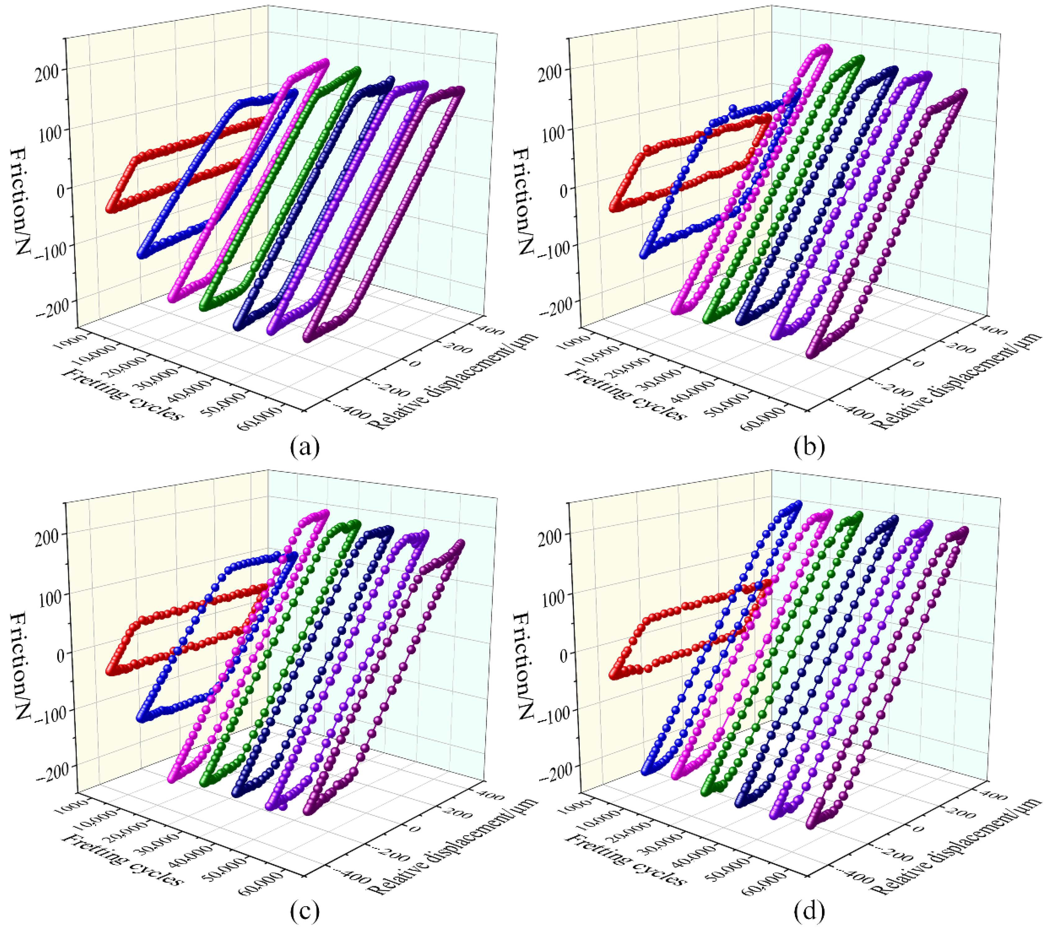
Figure 8 shows the evolution of hysteresis loops at different fretting frequencies. The evolution law of the hysteresis curve is roughly similar: they all evolve from the parallelogram representing the gross slip to the quasi-parallelogram representing the partial slip. The difference is that in the test groups with fretting frequencies of 0.5 Hz, 1.0 Hz and 2.0 Hz, the steel wire is still in gross slip at about 10,000 cycles and evolves into partial slip after 20,000 cycles. In the test group with a fretting frequency of 3, the fretting state evolved into partial slip after about 10,000 cycles. This indicates that a higher fretting frequency will have a faster fretting state evolution speed. At the same time, the hysteresis characteristics of steel wire are slightly different under different fretting speeds. The hysteresis curve of low frequency has larger slip and lower friction, and the hysteresis curve of high frequency has smaller slip and higher friction. This is because as fretting wear progresses, the surface topography of the contact area undergoes significant changes. The wear process may increase the root mean square (RMS) slope of the surface roughness [37,38]. According to recent research, due to the enhanced mechanical interlocking and plastic deformation at the rough contact points, this inevitably leads to an increase in the effective coefficient of friction. Concurrently, the wear debris generated (oxides and metallic particles) accumulates in the contact interface, forming a third-body layer. With cyclic compaction, this layer fills the valleys between asperities, effectively reducing the surface separation. This phenomenon, combined with the increased RMS slope, results in a pronounced mechanical interlocking effect that restricts tangential motion, thereby explaining the observed reduction in relative displacement. Meanwhile, the instantaneous temperature at high fretting frequencies is relatively high. The micro-ridges at the contact interface are more prone to undergo plastic deformation and adhesion, thereby increasing the frictional resistance of the steel wire and reducing the slip amplitude.
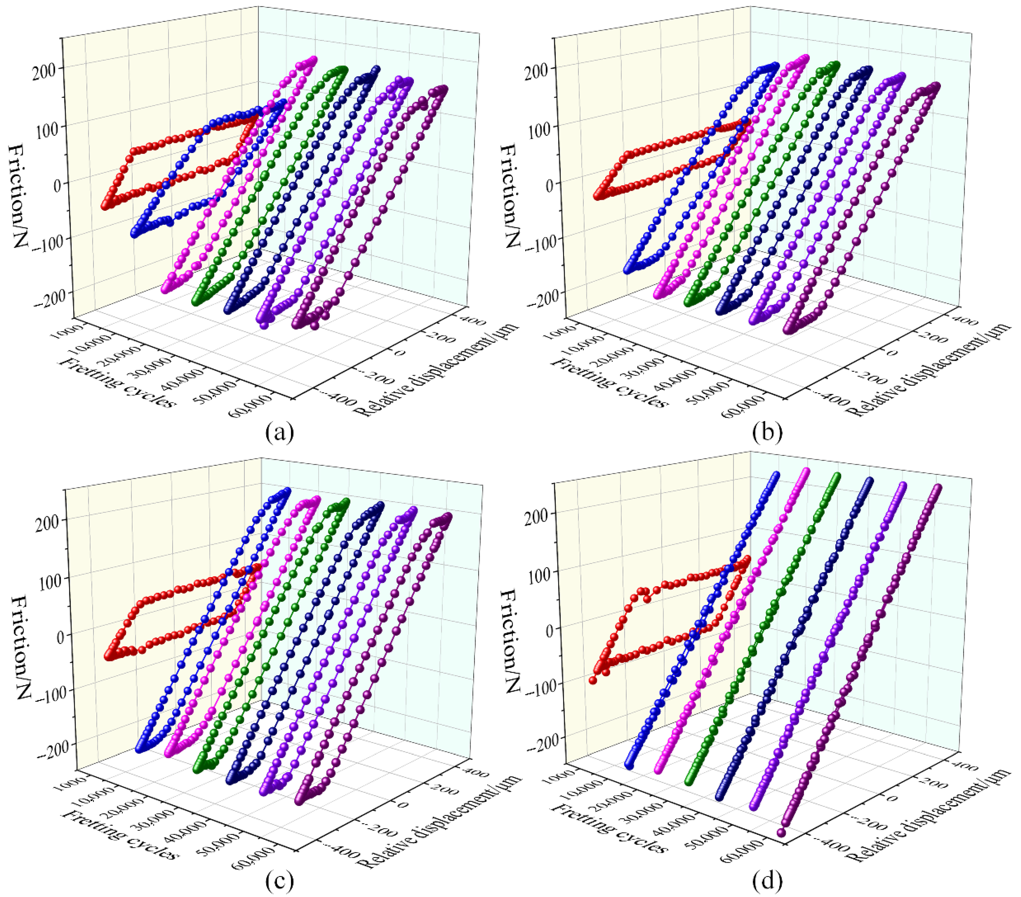
Figure 9 shows the hysteresis curve evolution under different tension conditions. When the tension was 60 N, 90 N and 120 N, the hysteresis loops evolved from a parallelogram (gross slip) to a quasi-parallelogram (partial slip). With the increase in tension, the friction is increasing, while the relative slip is decreasing. When the tension is 150 N, the hysteresis curve evolves from a parallelogram to a line. This means that the fretting state evolves from a gross slip state to a partial slip state to an adhesive state. In addition, the larger the tension, the faster the hysteresis curve evolves. The greater tension makes the contact force increase, which accelerates the damage of the steel wire surface and changes the fretting state between the steel wires.

3.3. Wear Characteristics

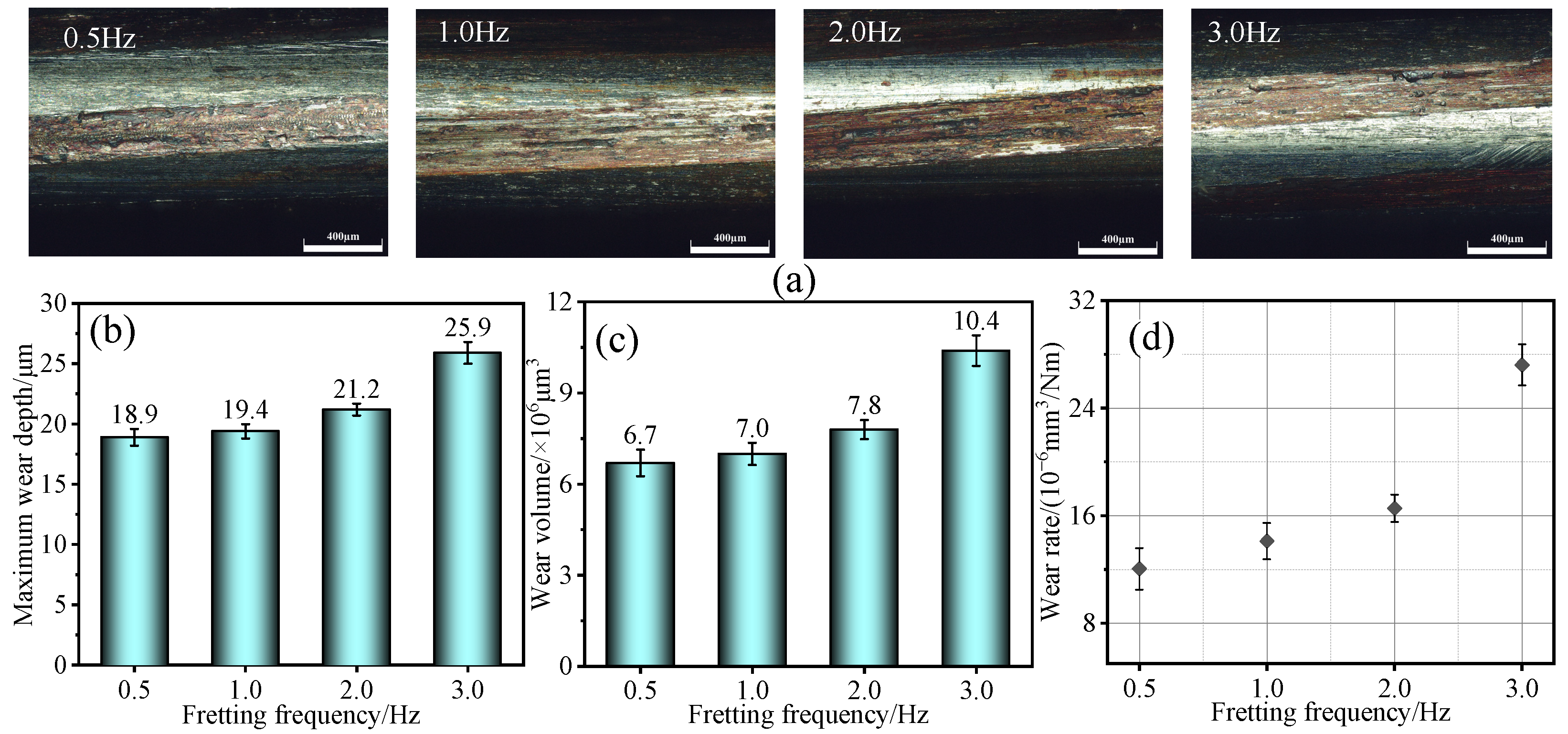
Figure 10a is the macroscopic image of the wear surface at different fretting frequencies. The wear scar width with lower fretting frequency is smaller, and the wear scar width with higher frequency is larger. In addition, there are still a large number of dark red oxides in the wear scar, which give rise to oxidation and accumulation of particles and debris in contact with air during the wear process. The maximum wear depth, wear volume and wear rate of the steel wire at different fretting frequencies are shown in Figure 10b–d. When the fretting frequency is 0.5 Hz, the maximum wear depth and wear volume are 18.9 μm and 6.7 × 106 μm3, respectively. When the fretting frequency increases to 3.0 Hz, the maximum wear depth and wear volume increase to 25.9 μm and 10.4 × 106 μm3, respectively. This indicates that the maximum wear depth and volume increase with fretting frequency, with a significant increase observed at 3.0 Hz. This is due to the instantaneous local high temperature caused by the high fretting frequency, which causes plastic deformation and surface spalling of the surface material. Moreover, high-frequency fretting causes an increase in stress cycle frequency and a faster accumulation of fatigue damage. Even if the stress amplitude of a single cycle is constant, the initiation and propagation rate of fatigue cracks will be accelerated. From the wear rate shown in Figure 10d, the wear rates of wires at low fretting frequencies (0.5 Hz, 1.0 Hz and 2.0 Hz) are low, which are about 12.1 × 10⁻⁶ mm3/Nm, 14.1 × 10⁻⁶ mm3/Nm and 16.6 × 10⁻⁶ mm3/Nm, respectively. At the high frequency of 3.0 Hz, the wear rate increased significantly to about 27.2 × 10⁻⁶ mm3/(N·m). This indicates that the wear rate not only increases with fretting frequency but also shows a marked difference between high and low frequencies.
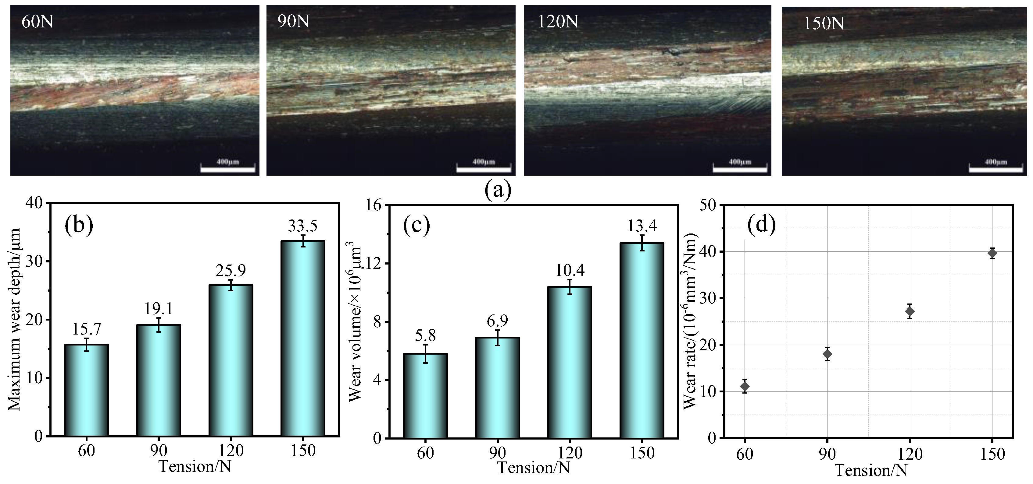
Figure 11a shows the macroscopic wear surface under different tension conditions. The width of the banded wear scars on the surface increases with tension. There are more dark red oxides inside the wear scar. Furthermore, the wear scars are measured and analyzed. Figure 11b–d show the wear parameters under different load conditions. The maximum wear depth and volume of the wires increased with tension. At 60 N, the wear depth is 15.7 μm and the volume was 5.8 × 106 μm3. When the tension increased to 150 N, these values rose to 33.5 μm and 13.4 × 106 μm3, respectively. This is because higher tension increases the contact stress between wires, accelerating the removal of surface material. From the wear rate shown in Figure 11d, as the tension increases from 60 N to 150 N, the wear rate of the steel wire increases from about 11.1 × 10⁻⁶ mm3/Nm to about 39.6 × 10⁻⁶ mm3/Nm. This indicates that the wear rate of steel wire increases significantly with the increase in tension. The higher tension will aggravate the wear damage rate and degree of the spiral contact steel wire.
The wear rate obtained in this study (on the order of 10−5 to 10−6 mm3/N·m) falls within the range reported in the literature [19,36] for fretting wear of high-strength steel wires, confirming the reliability of our quantitative wear assessment.

3.4. Wear Mechanism

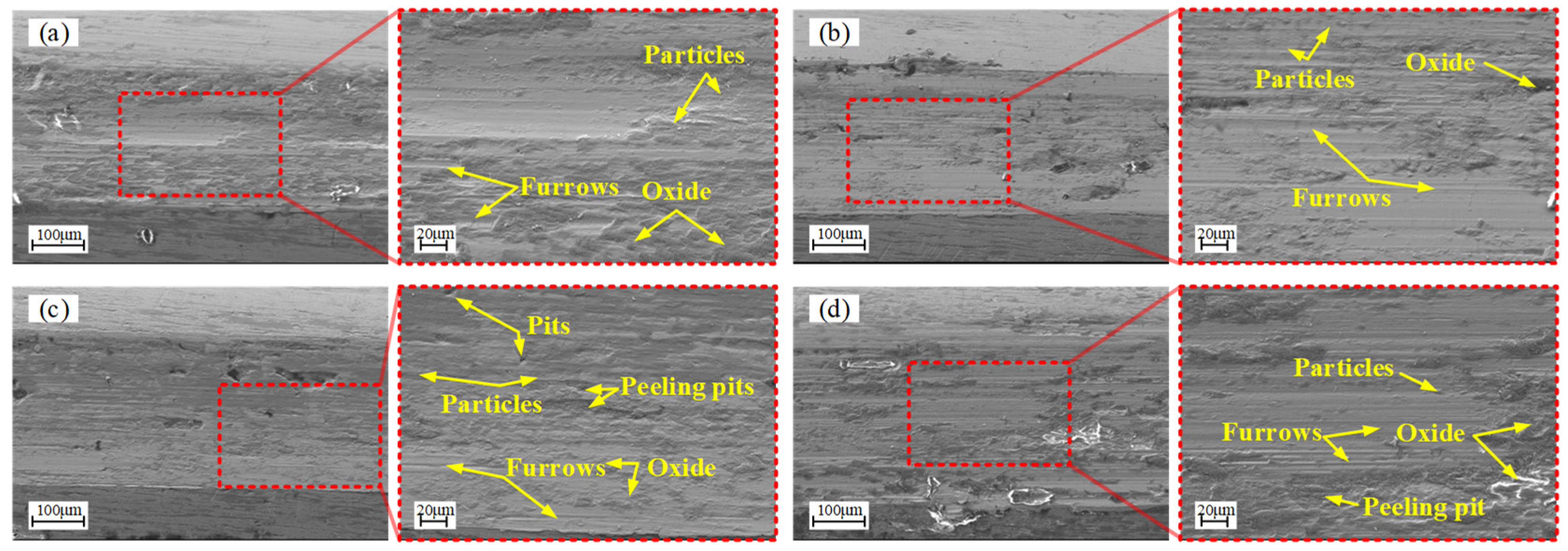
Figure 12 shows the microscopic morphology of worn wires under different fretting frequencies. The furrows inside the wear scars with fretting frequencies of 0.5 Hz and 1.0 Hz are the main morphology, and there are more wear particles and oxide deposits in the furrows. There are still more furrows inside the wear marks with fretting frequencies of 2.0 Hz and 3.0 Hz, accompanied by more pits and peeling pits. This is because the higher fretting frequency accelerates the fatigue of the surface and causes the material to peel off. In summary, the main wear sub-mechanisms with lower fretting frequency are microploughing (furrow), tribooxidation (oxide) and microcutting (particles). The main wear mechanisms of steel wires are abrasive wear and tribochemical reaction. On the basis of the original sub-mechanism, the main wear sub-mechanisms of steel wire with higher frequency add indentation (pits) and delamination (peeling pits). The main wear mechanisms are abrasive wear, tribochemical reaction and surface fatigue.
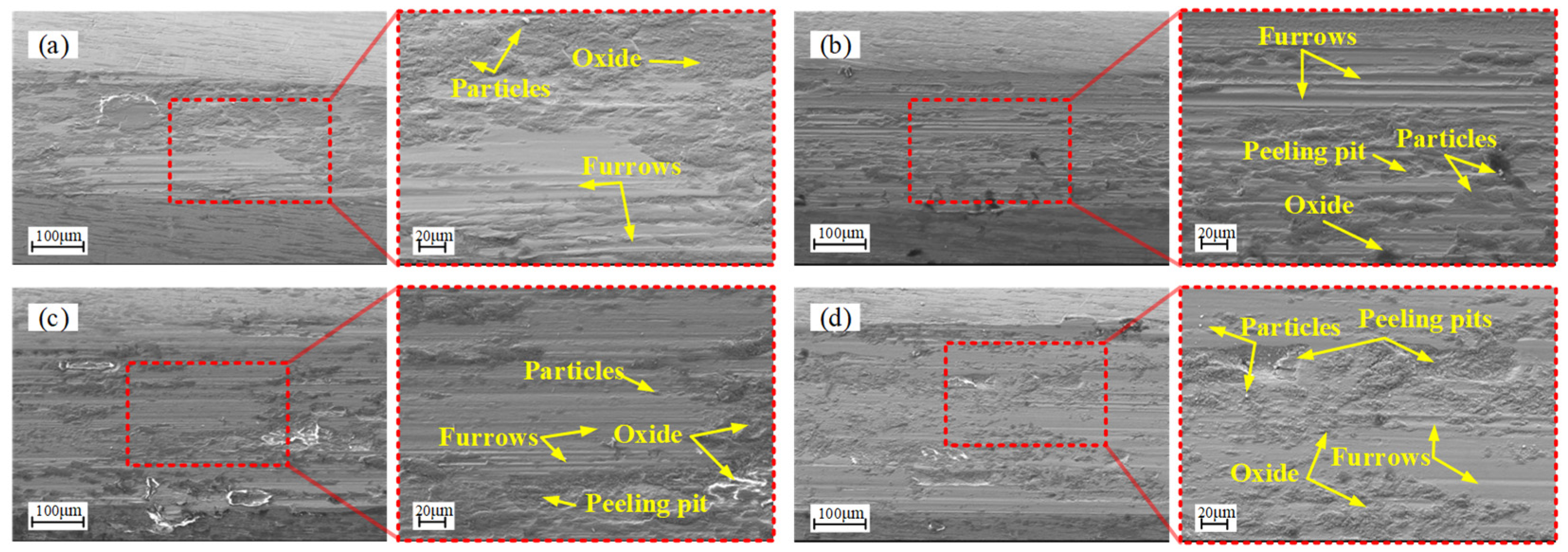
Figure 13 shows the microscopic morphology of worn steel wire under different tension conditions. An increased buildup of particles and granular oxides was observed within the wear scars. The main morphology of the steel wire wear scars with a tension of 60 N is the furrow, and there are also more deep and long furrows in the wear marks with a tension of 90 N. When the tension increases to 120 N and 150 N, there are also furrows, but compared with the first two groups, the number of furrows decreases, the depth decreases and the peeling pits and small pits increase. This is because as the tension increases, the contact force between the contact surfaces of the steel wires increases, the amount of slip decreases and the number of long furrows generated by slip decreases, which is replaced by peeling pits caused by high contact loads. In summary, the main wear sub-mechanisms are microploughing (furrow), microcutting (particles), indentation (pits), delamination (peeling pits) and tribooxidation (oxide). When the tension is low, the sub-mechanism of microploughing is more obvious. When the tension is high, the two sub-mechanisms of indentation and delamination appear and become more significant as the tension increases. The wear mechanisms with low tension are mainly abrasive wear and tribochemical reaction. The wear mechanisms with high tension are mainly abrasive wear, surface fatigue and tribochemical reaction.
The identified wear mechanism, particularly the dominant role of abrasive wear and frictional chemical reactions under low frequency/tension conditions, is consistent with the results of previous studies reported in the literature [27].

4. Conclusions

This paper mainly explored the friction and wear characteristics between spiral contact wires in mine hoisting rope under different service conditions (different fretting frequencies and wire tension). Service conditions jointly influence the friction and wear characteristics of the mine hoisting wire rope by triggering a transformation of the fretting state. The primary conclusions are as follows:
  • As the fretting frequency increases from 0.5 Hz to 3.0 Hz, the COF increases from 0.53 to 0.65, and as the wire tension increases from 60 N to 150 N, it decreases from 0.71 to 0.64. Fretting state evolves from gross slip to partial slip with the increase in fretting frequency. When the wire tension is 60 N to 120 N, the fretting state evolves from gross slip to partial slip, and when it increases to 150 N, the fretting regime transitions from an initial state of gross slip, through partial slip, and eventually to adhesion.
  • The wear depth, wear volume and wear rate of steel wire increase with the increase in fretting frequency, and increase to 25.9 μm, 10.4 × 106 μm3 and 27.2 × 10⁻⁶ mm3/Nm at 3.0 Hz, respectively. With the increase in wire tension from 60 N to 150 N, the wear depth, wear volume and wear rate increased to the maximum of 33.5 μm, 13.4 × 106 μm3 and 39.6 × 10⁻⁶ mm3/Nm, respectively.
  • The main wear mechanisms with low fretting frequency are abrasive wear and tribochemical reaction, and the main wear mechanisms of steel wire with higher frequency increase surface fatigue; when the tension is high, the two sub-mechanisms of indentation and delamination appear and become more significant with the increase in tension. The wear mechanisms with low tension are mainly abrasive wear and tribochemical reaction. The wear mechanisms with high tension are mainly abrasive wear, surface fatigue and tribochemical reaction.

Author Contributions

Conceptualization, K.H. and G.L.; methodology, K.H.; software, K.H.; validation, X.C. and Y.P.; formal analysis, K.H.; investigation, Y.P.; resources, G.L.; data curation, Z.Z.; writing—original draft preparation, K.H. and G.L.; writing—review and editing, X.C.; visualization, R.D.; supervision, Z.Z.; project administration, R.D.; funding acquisition, X.C. All authors have read and agreed to the published version of the manuscript.

Funding

This research was funded by the Key Laboratory of Intelligent Operation and Maintenance of High-parameter Lifts, State Administration for Market Regulation (JSTJ-IOMHL-202505). This project is also supported by the National Natural Science Foundation of China (Grant No. 52475234 and 52475174).

Data Availability Statement

The original contributions presented in this study are included in the article. Further inquiries can be directed to the corresponding author(s).

Acknowledgments

The authors wish to thank Top-notch Academic Programs Project of Jiangsu Higher Education Institutions (TAPP, China) and the Project Funded by the Priority Academic Program Development of Jiangsu Higher Education Institutions (PAPD, China).

Conflicts of Interest

The authors declare no conflicts of interest.

References

  1. Singh, R.P.; Mallick, M.; Verma, M.K. Studies on the failure behaviour of wire rope used in underground coal mines. Eng. Fail. Anal. 2016, 70, 290–304. [Google Scholar] [CrossRef]
  2. Hobbs, R.E.; Raoof, M. Mechanism of fretting fatigue in steel cables. Int. J. Fatigue 1994, 16, 273–280. [Google Scholar] [CrossRef]
  3. Krishnadev, M.; Larouche, M.; Lakshmanan, V.I.; Sridhar, R. Failure Analysis of Failed Wire Rope. J. Fail. Anal. Prev. 2010, 10, 341–348. [Google Scholar] [CrossRef]
  4. Wang, D.G.; Zhang, D.K.; Ge, S.R. Effect of terminal mass on fretting and fatigue parameters of a hoisting rope during a lifting cycle in coal mine. Eng. Fail. Anal. 2014, 36, 407–422. [Google Scholar] [CrossRef]
  5. Kumar, K.; Goyal, D.; Banwait, S.S. Effect of key parameters on fretting behaviour of wire rope: A review. Arch. Comput. Method E 2020, 27, 549–561. [Google Scholar] [CrossRef]
  6. Chen, Y.P.; Meng, F.M.; Gong, X.S. Full contact analysis of wire rope strand subjected to varying loads based on semi-analytical method. Int. J. Solids Struct. 2017, 117, 51–66. [Google Scholar] [CrossRef]
  7. Chen, Y.P.; Meng, F.M.; Gong, X.S. Interwire wear and its influence on contact behavior of wire rope strand subjected to cyclic bending load. Wear 2016, 368, 470–484. [Google Scholar] [CrossRef]
  8. Hu, Z.; Wang, E.Y.; Jia, F.Y. Mechanical and wear behavior of steel wires in typical contact area under tension-tension fatigue. Tribol. Trans. 2022, 65, 282–295. [Google Scholar]
  9. Urchegui, M.A.; Tato, W.; Gómez, X. A method for evaluating fretting wear scars in thin steel roping wires based on confocal imaging profilometry. J. Test. Eval. 2007, 35, 357–363. [Google Scholar] [CrossRef]
  10. Zhang, Q.; Peng, Y.X.; Zhu, Z.C.; Chang, X.D.; Lu, H.; Zhou, Z.; Cao, G.H.; Tang, W.; Chen, G.A. Influence of longitudinal vibration on the friction and wear characteristics of multi-layer winding hoisting wire rope. Wear 2022, 492–493, 204211. [Google Scholar] [CrossRef]
  11. Zhang, Q.; Peng, Y.X.; Zhu, Z.C.; Chang, X.D.; Lu, H.; Zhou, Z.; Jiang, F.; Tang, W.; Chen, G.A. Tribo-failure characteristics of the multilayer winding hoisting wire ropes with two different structures under vibration. Eng. Fail. Anal. 2022, 140, 106538. [Google Scholar] [CrossRef]
  12. Ma, W.; Lubrecht, A.A. Temperature of a sliding contact between wire rope and friction lining. Tribol. Int. 2018, 120, 140–148. [Google Scholar] [CrossRef]
  13. Peng, Y.X.; Wang, G.F.; Zhu, Z.C.; Chang, X.D.; Lu, H.; Tang, W.; Jiang, F.; Chen, G.A. Effect of low temperature on tribological characteristics and wear mechanism of wire rope. Tribol. Int. 2021, 164, 107231. [Google Scholar] [CrossRef]
  14. Harris, S.J.; Waterhouse, R.B.; Mccoll, I.R. Fretting damage in locked coil steel ropes. Wear 1993, 170, 63–70. [Google Scholar] [CrossRef]
  15. Waterhouse, R.B.; Mccoll, I.R.; Harris, S.J.; Tsujikawa, M. Fretting wear of a high strength heavily work-hardened eutectoid steel. Wear 1994, 175, 51–57. [Google Scholar] [CrossRef]
  16. Cruzado, A.; Hartelt, M.; Wäsche, R.; Urchegui, M.A.; Gómez, X. Fretting wear of thin steel wires. Part 1: Influence of contact pressure. Wear 2010, 268, 1409–1416. [Google Scholar] [CrossRef]
  17. Cruzado, A.; Hartelt, M.; Wäsche, R.; Urchegui, M.A.; Gómez, X. Fretting wear of thin steel wires. Part 2: Influence of crossing angle. Wear 2011, 273, 60–69. [Google Scholar] [CrossRef]
  18. Cruzado, A.; Urchegui, M.A.; Gómeza, X. Finite element modelling and experimental validation of fretting wear scars in thin steel wires. Wear 2012, 289, 26–38. [Google Scholar] [CrossRef]
  19. Cruzado, A.; Urchegui, M.A.; Gómeza, X. Finite element modelling of fretting wear scars in the thin steel wires: Application in crossed cylinder arrangements. Wear 2014, 318, 98–105. [Google Scholar] [CrossRef]
  20. Cruzado, A.; Leen, S.B.; Urchegui, M.A.; Gómez, X. Finite element simulation of fretting wear and fatigue in thin steel wires. Int. J. Fatigue 2013, 55, 7–21. [Google Scholar] [CrossRef]
  21. Zhang, D.K.; Yang, X.H.; Chen, K.; Zhang, Z.F. Fretting fatigue behavior of steel wires contact interface under different crossing angles. Wear 2018, 400, 52–61. [Google Scholar] [CrossRef]
  22. Zhang, D.K.; Geng, H.; Zhang, Z.F.; Wang, D.G.; Wang, S.Q.; Ge, S.R. Investigation on the fretting fatigue behaviors of steel wires under different strain ratios. Wear 2013, 303, 334–342. [Google Scholar] [CrossRef]
  23. Zhang, D.K.; Shen, Y.; Xu, L.M.; Ge, S.R. Fretting wear behaviours of steel wires in coal mine under different corrosive mediums. Wear 2011, 271, 866–874. [Google Scholar] [CrossRef]
  24. Wang, D.G.; Zhang, D.K.; Ge, S.R. Finite element analysis of fretting fatigue behaviour of steel wires and crack initiation characteristics. Eng. Fail. Anal. 2013, 28, 47–62. [Google Scholar] [CrossRef]
  25. Wang, D.G.; Zhang, D.K.; Ge, S.R. Fretting-fatigue behaviour of steel wires in low cycle fatigue. Mater. Des. 2011, 32, 4986–4993. [Google Scholar] [CrossRef]
  26. Torkar, M.; Arzensek, B. Failure of crane wire rope. Eng. Fail. Anal. 2002, 9, 227–233. [Google Scholar] [CrossRef]
  27. Moradi, S.; Ranjbar, K.; Makvandi, H. Failure Analysis of a Drilling Wire Rope. J. Fail. Anal. Prev. 2012, 12, 558–566. [Google Scholar] [CrossRef]
  28. Lin, Y.C.; Chen, T.M.; Chang, W.F. Strength decay of wire ropes by corrosion and wear at different surface conditions. Mater. Test. 2022, 64, 809–819. [Google Scholar] [CrossRef]
  29. Shi, Z.D.; Chen, H.Y.; Wang, X.Y. Experimental study of mechanical properties on rusting steel wires. In Proceedings of the ISTM/2009: 8TH International Symposium on Test and Measurement, Chongqing, China, 23–26 August 2009; Volumes 1–6, pp. 2140–2142. [Google Scholar]
  30. Vukelic, G.; Vizentin, G. Damage-induced stresses and remaining service life predictions of wire ropes. Appl. Sci. 2017, 7, 107. [Google Scholar] [CrossRef]
  31. Tijani, A.; Meknassi, M.; Chaffoui, H. Effect of broken rope components and corrosion on damage evolution through its lifetime. J. Mater. Civil. Eng. 2017, 29, 04017035. [Google Scholar] [CrossRef]
  32. Slesarev, D.A.; Vorontsov, A.N. The probabilistic characteristics of estimation of the residual strength and operation lifetime of steel wire rope based on the results of non-destructive testing. Russ. J. Nondestruct. Test. 2016, 52, 95–101. [Google Scholar] [CrossRef]
  33. GB_T33955-2017; Steel Wire Rope for Mine Hoisting. China Standards Press: Beijing, China, 2017.
  34. JB/T11174-2011; High-Speed Intelligent Tubular Twisting Machine. China Machine Press: Beijing, China, 2011.
  35. Fouvry, S.; Kapsa, P.; Vincent, L. Analysis of sliding behaviour for fretting loadings: Determination of transition criteria. Wear 1995, 185, 35–46. [Google Scholar] [CrossRef]
  36. Wang, D.G.; Zhang, D.K.; Ge, S.R. Effect of displacement amplitude on fretting fatigue behavior of hoisting rope wires in low cycle fatigue. Tribol. Int. 2012, 52, 178–189. [Google Scholar] [CrossRef]
  37. Afferrante, L.; Putignano, C.; Menga, N.; Carbone, G. Friction in rough contacts of linear viscoelastic surfaces with anisotropic statistical properties. Eur. Phys. J. E 2019, 42, 80. [Google Scholar] [CrossRef] [PubMed]
  38. Müller, C.; Müser, M.H.; Carbone, G.; Menga, N. Significance of Elastic Coupling for Stresses and Leakage in Frictional Contacts. Phys. Rev. Lett. 2023, 131, 156201. [Google Scholar] [CrossRef] [PubMed]
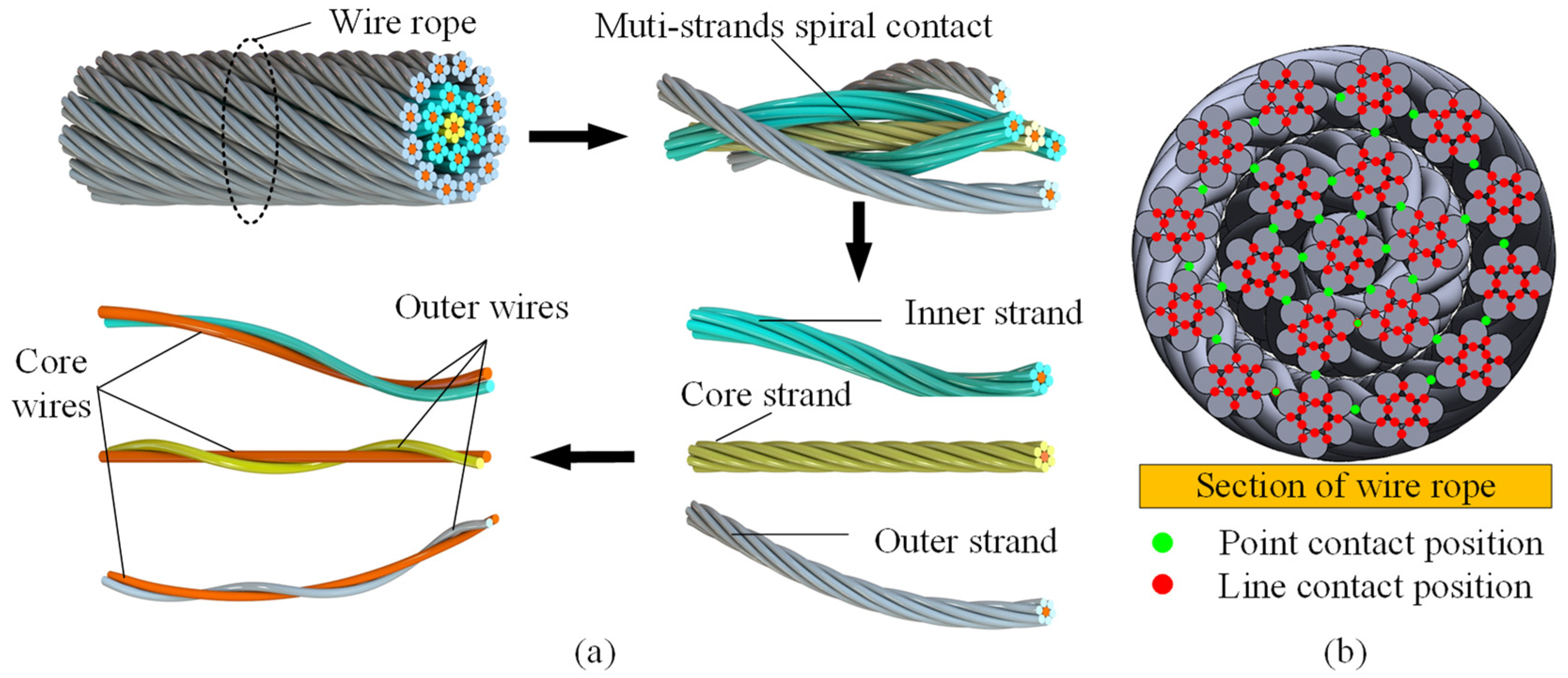
Figure 1. Mine hoisting rope: (a) wire rope strand structure, (b) internal contact of wire rope.
Lubricants 13 00453 g001
Figure 2. Multi-wire spiral contact fretting friction and wear test apparatus: (a) fretting wear testing device, (b) fretting loading area, (c) cross-section of the rope strand, (d) loading indication.
Lubricants 13 00453 g002
Figure 3. Schematic diagram of multi-wires spiral contact fretting wear test apparatus.
Lubricants 13 00453 g003
Figure 4. Friction characteristics between steel wires: (a) friction force data for several cycles of steel wires, (b) hysteresis curve and dissipated energy for a single cycle.
Lubricants 13 00453 g004
Figure 5. Analysis of worn wire wear characteristics: (a) wear parameters, (b) surface microstructure.
Lubricants 13 00453 g005
Figure 6. COF between wires under different fretting frequencies: (a) evolution curve, (b) steady-state value.
Lubricants 13 00453 g006
Figure 7. COF between steel wires under different tension: (a) evolution curve, (b) steady-state value.
Lubricants 13 00453 g007
Figure 8. Hysteresis loop evolution of wires with different fretting frequencies: (a) 0.5 Hz, (b) 1.0 Hz, (c) 2.0 Hz, (d) 3.0 Hz.
Lubricants 13 00453 g008
Figure 9. Evolution of hysteresis loop of wires under different tension conditions: (a) 60 N, (b) 90 N, (c) 120 N, (d) 150 N.
Lubricants 13 00453 g009
Figure 10. Characteristics of worn wire under different fretting frequencies: (a) wear surface, (b) maximum wear depth, (c) wear volume, (d) wear rate.
Lubricants 13 00453 g010
Figure 11. Wear characteristics under different tension conditions: (a) wear surface, (b) maximum wear depth, (c) wear volume, (d) wear rate.
Lubricants 13 00453 g011
Figure 12. Micro-morphology of steel wire wear under different fretting frequencies: (a) 0.5 Hz, (b) 1.0 Hz, (c) 2.0 Hz, (d) 3.0 Hz.
Lubricants 13 00453 g012
Figure 13. Microscopic morphology wear under different tension conditions: (a) 60 N, (b) 90 N, (c) 120 N, (d) 150 N.
Lubricants 13 00453 g013
Table 1. Chemical composition of steel wires.
ComponentFeCMnNiSiPS
Percentage/wt.%98.530.700.550.010.190.0120.008
Table 2. Physical properties of steel wires.
Diameter/mmTensile Strength/MPaModulus of Elasticity/GPaYield Strength/MPa
1/1.120602091570
Table 3. Test parameters for fretting wear of steel wires under different service conditions.
Fretting Wear Test ParametersValue
Lay angle/°11.6
Lay length/mm32.6
Side wire tension/N120
Initial stroke/μm±400
Loading/N160
Frequency0.5, 1.0, 2.0, 3.0
Cycles (103)65
Lubricating methodDry friction
Temperature/°C15 ± 5
Relative humidity/%65 ± 5
Disclaimer/Publisher’s Note: The statements, opinions and data contained in all publications are solely those of the individual author(s) and contributor(s) and not of MDPI and/or the editor(s). MDPI and/or the editor(s) disclaim responsibility for any injury to people or property resulting from any ideas, methods, instructions or products referred to in the content.