Article

Transition between Friction Modes in Adhesive Contacts of a Hard Indenter and a Soft Elastomer: An Experiment

by
Iakov A. Lyashenko
1,*,
Thao H. Pham
1 and
Valentin L. Popov
1,2,*
1
Department of System Dynamics and Friction Physics, Institute of Mechanics, Technische Universität Berlin, 10623 Berlin, Germany
2
Samarkand State University, Samarkand 140104, Uzbekistan
*
Authors to whom correspondence should be addressed.
Lubricants 2024, 12(4), 110; https://doi.org/10.3390/lubricants12040110
Submission received: 29 February 2024 / Revised: 22 March 2024 / Accepted: 25 March 2024 / Published: 28 March 2024
(This article belongs to the Special Issue Tribology in Germany: Latest Research and Development)

Abstract

:
The tangential adhesive contact (friction) between a rigid steel indenter and a soft elastomer at shallow indentation depths, where the contact exists mainly due to adhesion, is investigated experimentally. The dependencies of friction force, contact area, average tangential stresses, and the coordinates of the front and back edges of the contact boundary on the indenter displacement are studied. It is found that first a stick–slip mode of friction is established, which is then replaced by another, more complex mode where the phase of a global slip of the elastomer on the indenter surface is absent. In both regimes, the evolutions of friction force and contact area are analyzed in detail.

1. Introduction

Friction processes in the presence of adhesion play an important role in many technological processes. For example, due to the increasing use of electrical devices, MEMS (micro electric mechanical systems) have become a key technology in mechanical- and electrical-based domains. These systems are heavily influenced by adhesion, which causes “stiction”, the unintentional adhesion of a compliant microstructure surface. In the transport sector, adhesion and friction are a key component in road safety, as with the knowledge of the contact characteristics between rubber and pavement interaction, braking processes can be improved [1,2]. In the last decades, robots have been developed to help humans in dangerous work, such as detection, monitoring, cleaning, searching, and rescuing. Additionally, they are used, among other things, in ships, pipelines, nuclear power plants, and wind power generation. To increase the functional work area of robots, climbing robots were developed for the first time in the 1960s by Nishi et al. [3,4]. For wall-climbing robots, bio-inspired adhesive microstructures are of great interest, because these adhesive adsorption methods do not require an extra energy supply [4]. Based on the smooth, adhesive pads of cockroaches or patches of microscopic hairs of beetles and Tokay geckos, new adhesives are being developed for wall-climbing robots. In a gecko’s foot, there are up to five hundred thousand keratinous hairs or setae that each terminates in hundreds of spatula-shaped structures. Measurements of the adhesive force support the theory that the setae are operated by van der Waals forces [5]. For optimal functionality of the robots, not only the process of adhering to the surface is important; the detachment of the contacting parts is also as essential for locomotion of the robot as it is in biological organisms [6]. To break the strong adhesive forces of the entire adhesive pad of the connecting feet, much energy is needed. Therefore, a minimization of force expenditure during the detachment phase for reduced energy consumption is important. A shear component is present when the robot feet are moving along the wall. This provides a preload to the surface of the attaching feet. A similar shearing motion has been observed in the attachment mechanism of a single gecko seta. During the attachment phase, toe uncurling, and during the detachment phase, toe peeling can be observed in geckos, which increase the effectiveness of setae. It has been observed that setal forces are dependent on three-dimensional orientation and preloading during the initial contact. Experiments have shown that perpendicular preloading, by pushing the seta towards the surface, alone is not sufficient to form an effective setal attachment when the seta is pulled away from the surface. The experiment demonstrated that in addition to the initial push into the surface, a parallel pull of the seta along the surface increases the pull-away forces over ten times compared to systems where the setal was only perpendicularly preloaded [5]. For energetic advantages, a peeling-like detachment mechanism has been applied in some robot designs with climbing abilities [7]. To improve those systems, a deeper understanding of the behavior of friction and adhesion under normal and tangential loads is needed.
Many studies have been conducted on the strength of the contact when only a normal force is applied to separate the contacting bodies [8,9,10]. This study concentrates on the contacts where a tangential force is applied. The contact strength and, associated with that, the breakaway forces are of interest. The interaction between friction and adhesion is to be investigated due to the fact that adhesion is a partial reason for friction, but, at the same time, it decreases under a friction force [11]. In the present work, it is being determined in relation to the friction mode in which the system is operating.
The extension of the JKR theory (Johnson–Kendall–Roberts) to tangential forces was already made by Savkoor and Briggs in 1977 [12]. It has been observed that the contact area shrinks when tangential forces are present in adhesive contacts. Like in the experiments conducted in this study, the normal load is held near zero, and due to adhesion, a finite contact area can be observed. When a tangential load is applied, the surfaces can peel apart so that elastic energy is released at the expense of creating surface energy. However, after the release of shear stress, the surfaces can re-adhere without altering the potential energy of the tangential load [12]. With increasing tangential forces, the contact area decreases through peeling and transitions from a circular shape into an elliptical shape due to decreasing adhesive interaction [13]. After reaching a critical value of tangential load, the indenter can no longer stick to the surface and the contact either breaks or sliding occurs, depending on the normal load. The transition can occur smoothly [14,15] or via mechanical instability [16]. The abrupt decrease in the contact area at the transition towards gross sliding can only be observed at low, normal loads. This results from the fact that at higher loads and therefore bigger contact areas the contact can sustain larger tangential stress before sliding starts. The larger tangential load results in a more significant deformation of the contact and therefore a reduction in adhesion [11]. From experiments with dry sliding, it has been discovered that the tangential pull-off force is proportional to the contact area, which leads to constant frictional stress and independence on normal forces. Therefore, for low, normal forces where adhesion dominates, the critical tangential force for detachment can be described by Tc = τ0A, where τ0 is the critical shear stress at pull-off and A is the contact area at the peak tangential force [17].
To understand the processes in adhesive contacts, a large number of both theoretical and experimental investigations are being carried out. However, many scientific groups who have studied the dependence of the contact area on the tangential force, where the indenter is displaced at constant velocity, have either only observed the dependence right after normal loading and not over a long period of time (or, to be more precise, not over many periods of increasing and decreasing tangential force) [18] or the dependence until gross slipping was observed [14,15]. Therefore, it is unknown if there will be a transition to a different friction mode when sliding for a long time.
The aim of this work is to study the transition of friction modes in the case of a rigid sphere being displaced with a constant velocity at shallow indentation depths over a soft elastomer layer with which the sphere is in adhesive contact.

2. Materials and Methods

The experimental setup described in detail in our previous paper [19] was used for the experiments presented in this work, so we will not go into detail on its design here. In each experiment, a spherical indenter made of steel was first indented to a depth of dmax = 0.2 mm into a soft gel sheet (thermoplastic polystyrene-type gel sheet, CRG N3005, TANAC Co. Ltd., Gifu, Japan [20]) with thickness h = 5 mm and linear dimensions 100 mm × 100 mm. Because the material being used possesses elastomeric properties (non-compressibility [21], low modulus of elasticity, and ability to withstand large elastic deformations), we will further refer to it as elastomer. After the end of the indentation phase, the indenter was pulled out of the elastomer to the zero-level d = 0 mm, and then tangential shear was performed at a fixed zero indentation depth d. However, it should be noted that we used precision linear stages PI M-403.2DG, which allow us to fix the indenter position with an accuracy of up to 1 μm. But, when changing the direction of motion, these devices have backlash, which, in our case, was about 6 μm (see [19] for a detailed explanation). Because in the experiment the indenter was first indented to a depth of d = 0.2 mm, which is multiple times greater than the backlash value, and then pulled out of the elastomer, there was only a single change in the direction of its motion. Therefore, the indentation depth d, at which the tangential shift of the indenter was realized, is not d = 0 mm (which corresponded to the instrument readings), but d ≈ 6 μm, because the indenter in the pulling phase moves a distance shorter by the amount of backlash compared to the indentation phase. When using the more precise PI L-511.24AD00 linear stages, we discovered that in the case of exactly zero indentation depth d = 0 mm, the adhesive contact disappears completely during tangential shear. Therefore, the experimental results discussed below should be interpreted as corresponding to a shear indenter with a small, but non-zero indentation depth d. At this depth d, the contact exists mainly due to adhesion. It is worth noting that the experimental setup allows experiments to be conducted with a fixed indentation depth of indentation d, regardless of the value of the normal force, because a displacement-controlled mode (fixed grips) is used. Specifically, the indenter is displaced using actuators to which it is rigidly connected. Thus, in the experiment, force is not directly applied to the indenter; instead, its displacement is controlled, and all three components of the contact force are measured using a three-axis force sensor, as shown in Figure 1 by position (4).
Figure 1 shows a real photograph of the contact area in ongoing experiments, where elements of the experimental setup are partially depicted.
Here, a spherical steel indenter (1) is pressed into a sheet of soft elastomer (2), which is placed on a silicate glass plate to which it is firmly attached by its own adhesion, without the use of glue or any additional fixing mechanisms. The contact area is uniformly illuminated using comprehensive LED lighting (3), and contact forces are measured using the ME K3D40 three-axis force sensor (4). The contact is observed from below the system using a digital camera through the aperture visible in the figure. Because the contact in the experiments has a relatively small size, a 5 MP physical resolution camera–microscope (model TOOLCRAFT TO-5139594, Conrad Electronic SE, Hirschau, Germany) was used to observe it.
To ensure quasi-static contact propagation conditions, the indenter velocity in the experiment, both when indenting in the normal direction and in tangential shear, was v = 1 μm/s. Because the optically transparent elastomer TANAC CRG N3005 [20] was used in the experiments, direct observation of the contact was possible. In order to clearly observe the contact area, the indenter surface was treated with P800 grit sandpaper prior to each experiment series to provide diffuse light scattering from the LED side-lighting system. After the treatment with sandpaper, the indenter surface was cleaned with alcohol and then quickly dried with a jet of compressed air before the experiment was carried out. In our previous work [21], the values of the elastic modulus of the elastomer used in this study E ≈ 0.324 MPa and Poisson’s ratio ν ≈ 0.48 were determined by generalizing a large amount of experimental data. Because the indenter was made of steel, with an elastic modulus of E ≈ 2 × 10⁵ MPa, the indenter can be considered absolutely rigid, i.e., only the elastomer sheet could be deformed in the experiment.
In much earlier work by other authors [22], the experiments were conducted with a similar material, TANAC CRG N0505, but for a different contact geometry. Specifically, the study focused on sliding along the glass of an externally non-loaded elastomer sheet at various drawing velocities. However, the material CRG N0505 has a lower elasticity modulus, which means it can be deformed even more significantly under tangential shear, leading to more complex dynamic nonlinear effects; contact restructuring in the case of CRG N0505 is more complex than for stiffer CRG N3005 used in the present study. Our recent study [23] provides a comparison of the behavior of these two materials (the difference is particularly noticeable in supplementary videos attached to the article). Primarily, in our experiments, we prefer to use the stiffer material, CRG N3005. Stiffer gels contain less filler in the matrix (which can flow inside the material during deformation) and therefore exhibit properties closer to those of elastic solids, such as stable values of elasticity modulus and Poisson’s ratio [21]. It should be noted that gels with similar properties are produced by other companies as well. For instance, in the experimental work [24], an optically transparent material “Super Gel” (Kihara Sangyo Co., Ltd., Osaka, Japan) is used.

3. Results

3.1. Transition between Friction Modes in Adhesive Contact as a Result of Degradation of Adhesive Properties of Contacting Surfaces

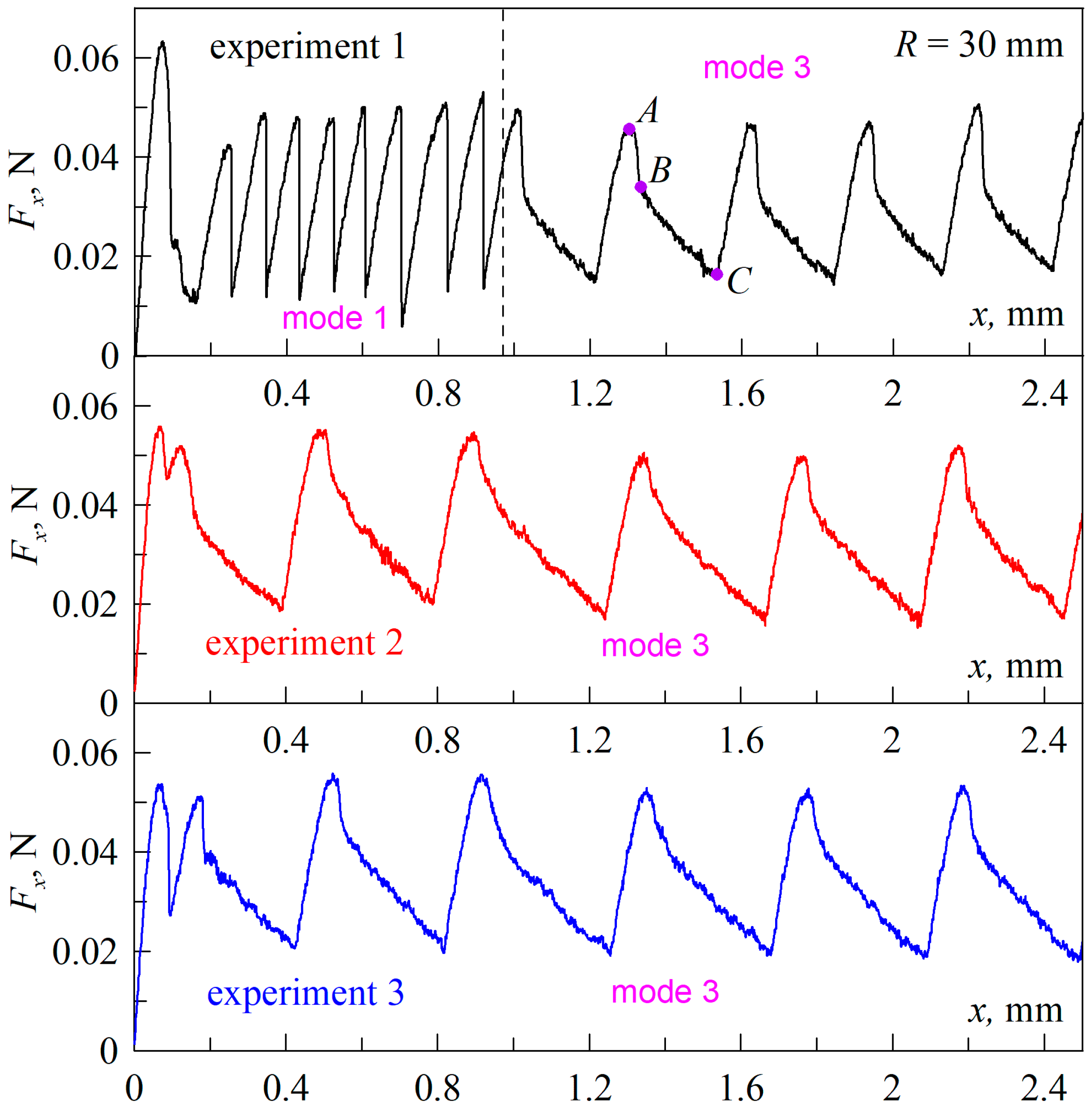
Figure 2 shows the experimentally measured dependencies of the friction force Fx on the value of tangential displacement x of the indenter, where the results of three consecutive experiments are depicted in different panels. In each experiment, the indenter was first immersed to a depth of dmax = 0.2 mm then pulled to a zero level of d = 0.0 mm, followed by tangential displacement. Moreover, the initial indentation to a depth of dmax in all experiments was carried out at the same location of the elastomer to ensure the same experimental conditions. Figure 2 shows the dependence plots corresponding to tangential shear without indentation and detachment phases in the normal direction, where the indenter was not horizontally displaced (i.e., x = 0 mm). In the first experiment (upper panel), after the motion starts, the tangential force first increases to some maximum and then decreases. This maximum is associated with additional strengthening of the contact during normal indentation when tangential shift did not occur; a similar situation was observed in [22] for another geometry of the experiment and much bigger sliding velocities. At further shear, as it follows from the figure, a stationary mode of stick–slip friction mode is established, which we denote as “mode 1”. In this stick–slip mode, once the friction force reaches its maximum value, it decreases sharply, which can only be due to gross slip, i.e., “mode 1” is a stick–slip mode in the classical sense. Such a mode can be theoretically described within the framework of models existing in the literature, such as, for example, [25]. However, in the present work, we limited ourselves to a detailed description of the experiment.
In order to realize the stick–slip motion, it is necessary for the system to be able to store elastic energy that is released during the slip phase. The stick–slip mode is often studied using examples of systems in which one of the rubbing surfaces is displaced by a spring, the free end of which moves at a constant velocity [26,27]. In this case, the elastic energy is stored in the spring, and as soon as the contact stresses exceed a critical value, the rapid slip phase takes place. In the slip phase, the spring tension decreases, and in order for the tension to reach the critical value again, time is required during which the contacting surfaces come to rest. As a result, a stick–slip friction mode is established, in which periods surfaces stopping alternate with periods of rapid slipping. Any elastic body with a stiffness much smaller than the tangential contact stiffness, such as a cantilever in AFM (atomic force microscopy) experiments, in which the stick–slip mode is also observed, can act as a spring [28]. In the experiment, the results of which are shown in Figure 2, the indenter (upper rubbing surface) is rigidly connected to the driving actuator and is displaced at a constant velocity. In this case, the elastic energy is accumulated by deforming a part of the rubber layer in the contact area, because the rubber surface in the stick phase moves together with the indenter. When the shear stresses exceed the critical stresses, the rubber slips over the indenter with the release of elastic energy and the friction force decreases dramatically (“mode 1” in Figure 2). Therefore, in the described experiment, there is no rapid movement of the whole rubber sheet (lower rubbing surface) or the indenter (upper rubbing surface); the indenter always moves at a constant velocity, and the rubber rests on a rigidly fixed glass substrate.
It is worth noting that in the experiment, the indenter is shifted at a very low velocity v = 1 μm/s to ensure quasi-static contact conditions. During the “stick” phase, the contact can be considered quasi-static because the elastomer surface moves together with the indenter. However, during the “slip” phase, the elastomer slips over the indenter surface at a much higher velocity, exceeding the value at which the contact can be considered quasi-static. Therefore, to describe the observed contact processes, even with the indenter moving at very low velocities, it is necessary to take into account viscoelastic effects, which significantly complicates the theoretical description of the problem [29,30]. There are also studies that investigate the influence of velocity on contact properties, such as, for instance, [22,24].
The top panel in Figure 2 shows that over time, the stick–slip mode, denoted as “mode 1”, is replaced by another mode, labeled “mode 3”. In “mode 3”, there is no phase of global slippage of the rubber on the indenter surface because of the absence of a sharp decrease in the friction force. Note that the form of friction force–displacement dependence in “mode 3” is typical for adhesive contacts at shallow indentation depths, and such dependencies were observed by us in previous works, such as, for example, [31,32]. Such a “mode 3” was thoroughly analyzed in our latest work [33] in which extensive analysis was conducted based on existing theories of tangential adhesive contact. In [33], it was shown that such a mode consists of alternating phases, such as attachment, stick, peeling, and sliding, which periodically repeat.
The different panels in Figure 2 show the results of three consecutive experiments, where only “mode 3” was observed in the second and third experiment. In order to eliminate the influence of individual elastomer surface characteristics, the indenter motion started at the same location on the rubber substrate in each experiment. From a comparison of all of the curves in Figure 2, an interesting feature emerges. On the dependencies Fx(x), which correspond to “mode 3”, after the friction force reaches its maximum value, its rapid decrease is observed for some time (section AB), although it is not instantaneous as in the stick–slip mode (also known as “mode 1”). After a rapid decrease in the friction force, it continues to decrease, although now much more slowly (section BC). When the friction force becomes minimal (point C), it starts to increase to its maximum value again. The above-mentioned peculiarity consists in the fact that as time passes, the section AB, where the friction force rapidly decreases after reaching the maximum value, becomes shorter, whereas the section BC, on the contrary, becomes longer. As a result, the period of transitions between maxima and minima of the friction force, observed in the Fx(x) dependencies, increases.
It has already been mentioned above that in the first experiment (upper panel in Figure 2), after the start of indenter shear, the frictional force reaches some maximum value, which is significantly higher than the maximal force during further indenter shear. This maximum of Fx during the transition from static to kinetic friction is due to the fact that the initial contact is stronger than the contact after the first act of slip in the kinetic regime [34]. However, no such high peaks are observed in the next two experiments (middle and bottom panels in Figure 2), i.e., the contact before shear has the same strength as in the steady kinetic regime. This fact suggests that the adhesive strength of the contact decreases with time. The decrease in the shear strength of the contact was observed by us in previous works and was expressed as a decrease in the steady-state value of the friction force and shear stresses in the sliding mode [32]. The adhesive strength of the contact depends on the surface energy of the contacting bodies, which determines the specific work of adhesion Δγ. It has been repeatedly shown that freshly cleaned surfaces have the highest value of Δγ, which decreases with time due to the oxidation of friction surfaces, their contamination, etc. We attribute the transition between “mode 1” and “mode 3”, observed in the upper panel of Figure 2, to the decrease in the specific work of adhesion Δγ due to the contamination of the indenter surface during friction. Thus, large values of Δγ should correspond to “mode 1”. It should be noted that if the indenter is left exposed to air for some time before the experiment (for example, for one day), then “mode 3” will be observed immediately in the experiment. This is because the adhesive properties of the freshly treated surface of the indenter degrade rapidly, particularly due to surface oxidation. This is one of the reasons why we did not observe such a transition between modes earlier, as we did not conduct experiments immediately after cleaning the indenter. However, in any case, during interaction with the elastomer surface in the experiment, the adhesive properties of the indenter surface degrade much faster than when it is passively exposed to the air.
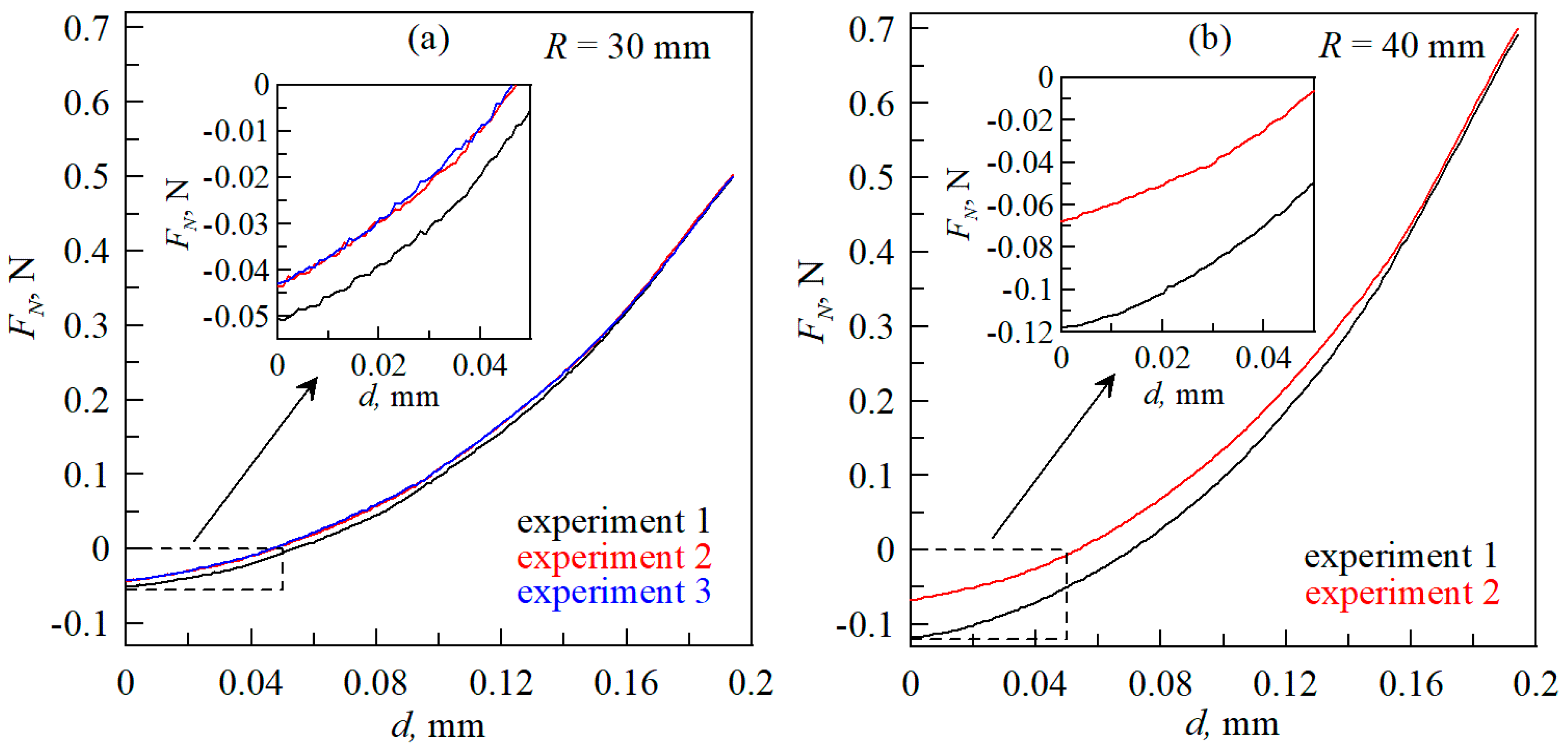
The assumption that the transition between “mode 1” and “mode 3” is caused by a decrease in the specific work of adhesion Δγ is also supported by the results shown in Figure 3. This figure shows the dependencies of the normal force FN on the indentation depth d in the indenter pulling phase after the initial indentation to a depth of dmax = 0.2 mm (in the figure, the dependencies do not reach the value of 0.2 mm because of the range of instrument backlash, which is described in Section 2 of the article). Figure 3a shows three curves corresponding to three consecutive experiments, the results of which are shown in Figure 2. All of the dependencies in Figure 3a correspond to the indenter pulling back to the zero level, and, after reaching that level, the indenter already starts to shift in the tangential direction.
Figure 3 shows that the highest absolute value of the adhesion force FN < 0 N is realized in the first experiment, while the following two experiments show similar adhesion forces. But, according to Figure 2, only in the first experiment the transition between friction modes takes place, while in the second and in the third experiments, only “mode 3” is realized. The data shown in Figure 3b show the dependencies of normal forces on indentation depth for two consecutive experiments, which are similar to those discussed above, only with an indenter with a radius R = 40 mm. Figure 3b also shows a decrease in the adhesive force in the second experiment compared to the first one. Thus, the data shown in Figure 2 and Figure 3 complement each other and speak in favor of the fact that the change in friction modes is caused by contamination of the indenter surface, which occurs due to its interaction with the elastomer during the contact.
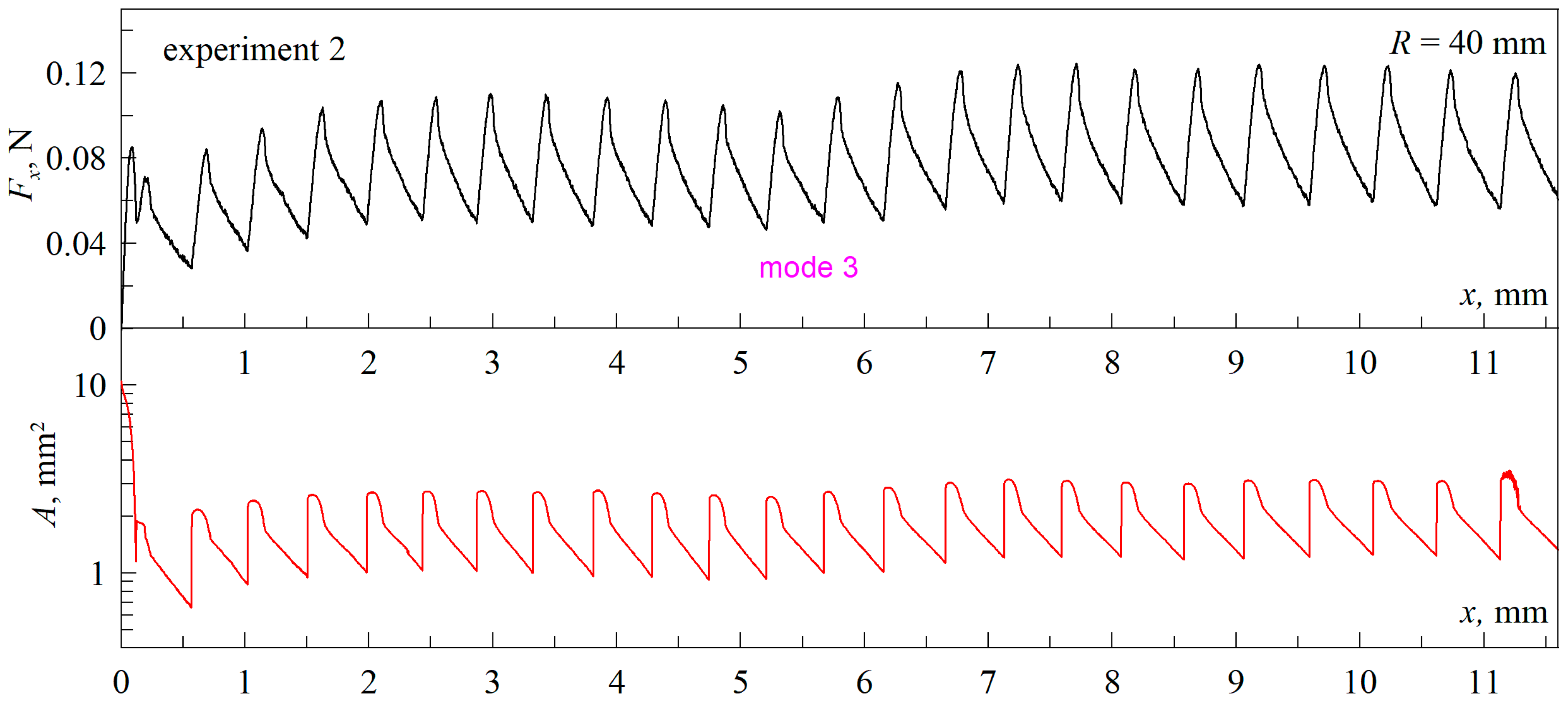
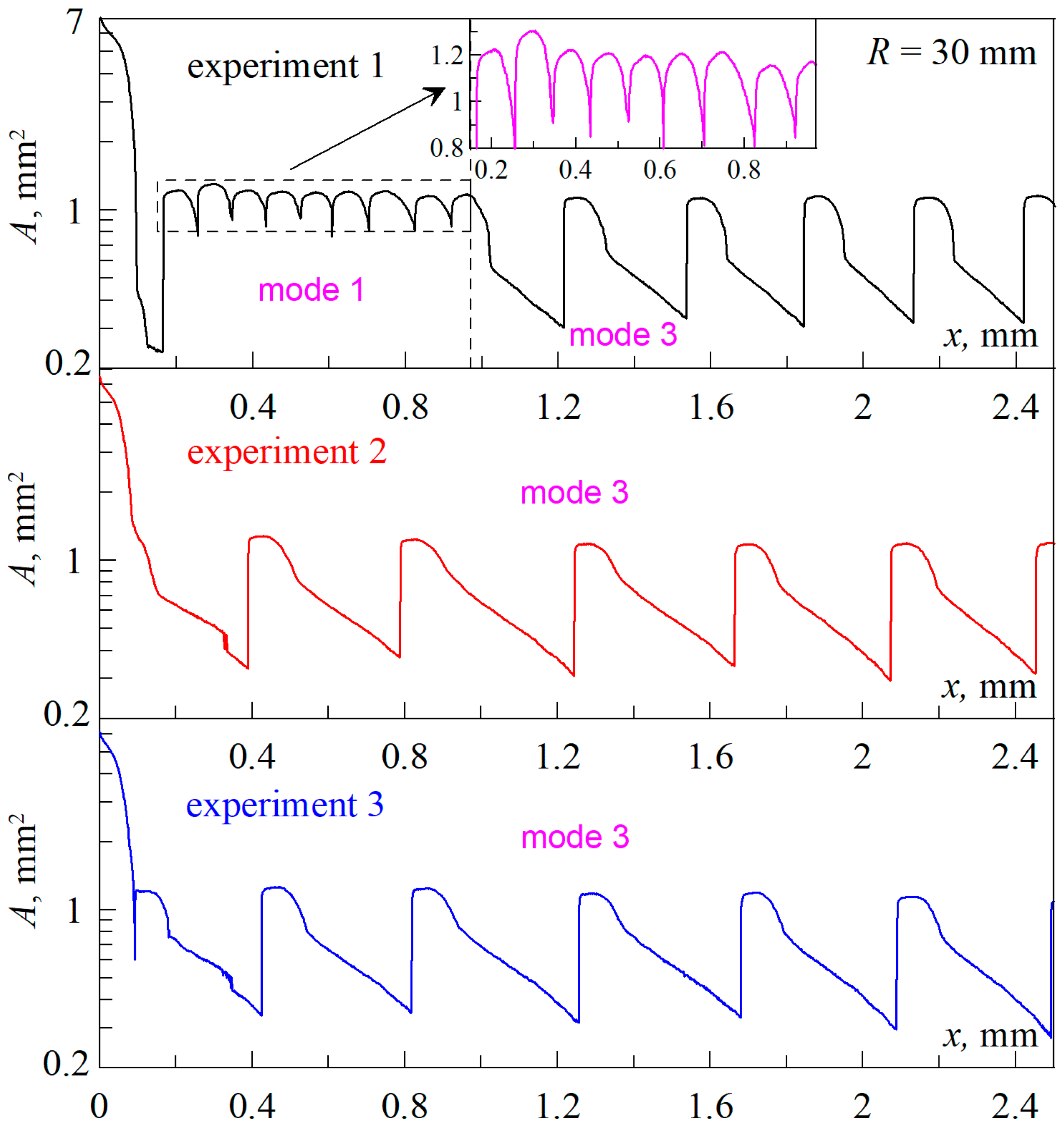
Figure 4 shows the dependence of the contact area A on the indenter shear x, which complements the experimental data shown in Figure 2. In order to show the initial decrease in area from a much larger value of A ~ 7 mm2 along with the periodic stationary regime, in which A ~ 1 mm2, the ordinate axis is presented on a logarithmic scale. Figure 4 shows that in stick–slip mode (“mode 1”), the contact area A varies within a small range, while in “mode 3” the area varies much more. Our previous work [31,32] studied in detail the nature of contact propagation in the stationary regime, which resembles “mode 3”, but in the mentioned work, the case of an indentation depth d significantly different from zero was considered. Here (Figure 2 and Figure 4), we study the situation when the indentation depth d is close to zero and the contact exists mainly due to adhesion. Therefore, this case requires additional analysis, which is carried out in the next section of the paper.

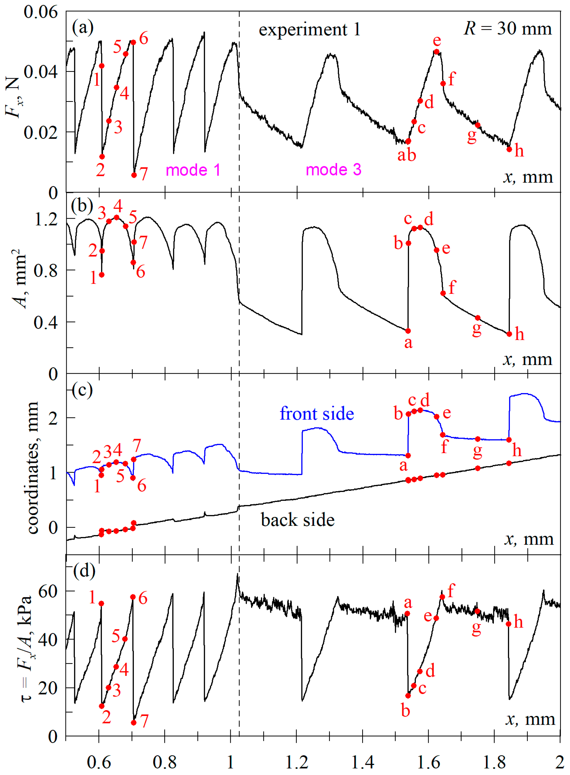
3.2. Detailed Analysis of the Nature of Contact Propagation

Figure 5 shows the dependencies corresponding to the first experiment, the data of which are presented in Figure 2 and Figure 4. In Figure 5, the region of the dependencies in which the transition between modes “mode 1” and “mode 3” takes place is depicted in detail. Additionally, Figure 5 shows the dependencies for the coordinates of the front and back contact edges, as well as the average value of the tangential stresses τ = Fx/A. Note that the difference between the “front side” and “back side” coordinate values in Figure 5c at each fixed indenter coordinate x is the contact width measured in the direction of indenter motion. In the case of a circular contact, the width thus measured will coincide with its diameter.
Let us first consider the stick–slip mode (“mode 1”), which exists up to the vertical dashed line shown in Figure 5. In all dependencies in 
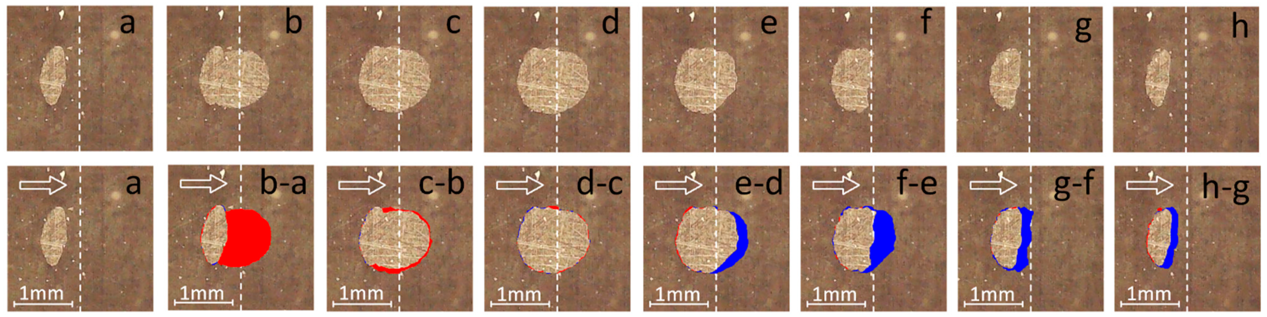
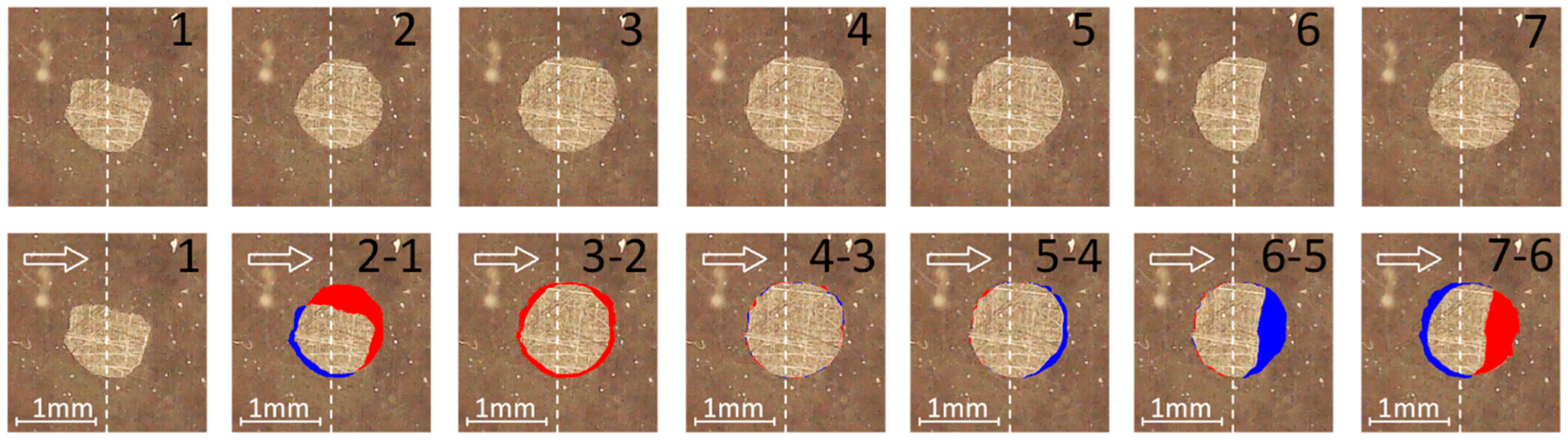
Figure 5, the numbers from one to seven show characteristic points corresponding to moments for which pictures of the contact area are shown in the top row in Figure 6. The bottom row in Figure 6 shows the same photos as in the top row, but the colors indicate differences between adjacent contact areas. Blue shows areas that have come out of contact and red shows areas that have come back into contact. This, however, does not apply to the first picture “1” in the bottom row, which is exactly the same as the corresponding image in the top panel.
Let us note one important point for understanding. In Figure 6, the contact configurations and their changes are shown in the coordinate system that is associated with the indenter, i.e., the indenter is assumed to be stationary. At the same time, the coordinate dependencies of the back and front of the contact boundary, which are shown in Figure 5c, are shown in the coordinate system associated with the rubber substrate, i.e., here, the elastomer into which the indentation is made is considered to be stationary. Therefore, for example, in the case where the rear edge of the contact is moving at the same speed as the indenter, Figure 6 will show no change in the rear edge, and Figure 5c will show a linear increase in the “back side” coordinate.
Let us now analyze the contact realignment process based on the figures presented above. Point 1 in Figure 5 is selected just before the next contact propagation. This point corresponds to the friction force Fx close to the maximum, as well as the maximum contact stresses τ. At the neighboring point 2, there is a jump in the contact area when the region at the front edge, shown in red in panel “2–1” in Figure 6, is joined. In addition to the discontinuous joining of a new contact area, there is a global slip of the rubber over the indenter surface in the entire contact area as the friction force decreases discontinuously, as demonstrated by trajectory 1–2 in the Fx(x) dependence. As the contact slips and recovers, its size becomes slightly smaller on the back edge, as can be seen in panel “2–1” in Figure 6. The reason for this reduction is that part of the contact at the back edge, prior to slippage, existed due to normal adhesion, and it takes time to restore it. At global slip 1–2, the elastic energy stored in the deformed rubber layer sample is released, and for the next slip cycle (points 6–7), the rubber layer must deform again to the critical state to which the maximum values of friction force Fx and tangential stresses τ correspond. Note that the force Fx before global slippage always takes locally maximal values. The reason that the friction force at point 1 is not maximal is due to the fact that the contact characteristics (contact forces and photos of the contact area) are saved in the experiment with a small frequency of once per second, and the next preservation at point 1 occurred after the beginning of global slippage. After the act of slippage, the friction force and shear stresses increase monotonically (path 2–3–4–5–6). However, the contact area on this site behaves non-monotonically, which was observed earlier in [32]. The friction force in the stationary sliding mode is defined by the expression
Fx = τ0A,
where τ0 is the critical stress at which sliding is realized. According to (1), as the area A increases, the tangential force Fx also increases. However, this is only true for those systems in which the stresses τ0 takes on constant values over the entire contact region. And, here we have a case with a complex inhomogeneous stress distribution. For example, in the photo “2–1” in Figure 6, the shear stresses in the “fresh” contact region at the front edge (shown in red) have close to zero values because it is a newly formed region after global slippage and has not yet been loaded by the tangential motion of the indenter. In the rest of the contact region, non-zero stresses τ are realized, and they are the ones that provide the non-zero force Fx. However, the stresses τ for this configuration (point 2) are significantly lower than the maximum value of τ0, because global slip across the contact region (path 1–2) and the release of elastic energy have just occurred.
In addition to the above, it should also be taken into account that in a tangential contact, the maximum stresses are realized at its boundary [35]. Because contact failure begins when the stress reaches its maximum value, as the tangential force increases, contact failure will begin at the edge of the contact, as seen, for example, in panel “5–4” in Figure 6, which demonstrates the partial detachment of the rubber from the indenter at the front edge of the contact. The next panel of the figure “6–5” shows a significant reduction of the contact area due to its failure at the front edge, which corresponds to the moment of onset of global slippage at which the frictional force Fx and the average tangential stresses τ take their maximum values. During further slipping, the tangential stresses decrease across the entire contact area, with immediate contact regaining at its front edge when the tangentially unloaded area is joined (red area in panel “7–6” in Figure 6). The contact configuration in panel 7 in Figure 6 is similar to panel 2, as they correspond to the moments immediately after slip and the minimums of the force Fx. The described process is repeated periodically in time and corresponds to a stationary stick–slip motion in which, however, the minimum and maximum values of the tangential force Fx and the contact area A vary in some range. Such variations occur due to the fact that compared to the quasi-static shear of the indenter with a very small velocity, the process of global slippage of the rubber on the indenter surface is almost instantaneous. Therefore, an essential role here is played by the individual characteristics of the contact before the slip phase, which are always different in a real experiment (specific contact configuration, stress distribution, surface energy distribution of the contacting surfaces, presence of inhomogeneities, etc.).
Let us note one interesting detail that is visualized in panel “3–2” in Figure 6. Panel 2 of the figure is the contact configuration immediately after global slippage, and panel 3 is the next contact configuration that corresponds to the section of monotonic force buildup. What is common in panels 2 and 3 is that here the stresses τ are still far from the critical value at which slip is realized. The characteristic mentioned above is that the contact area on panel 3 is slightly larger than on panel 2. The newly acquired contact areas are shown in red in the “3–2” panel, indicating homogeneous contact propagation on all sides. It has been shown many times before that the contact area can only decrease with tangential shear (see, e.g., [36,37]). The reduction of the area in the tangential contact is caused by tangential stresses, which, however, are quite small immediately after slip. Therefore, the increase in contact area shown in panel “3–2” is due to contact propagation in the normal direction (normal adhesion). This spreading of the contact due to normal adhesion, however, leads to only a small increase in the contact area, so that already in panel 4 of Figure 6 the contact area is almost unchanged compared to panel 3 (see comparison panel “4–3”). The described contact rearrangement process is periodic in time and corresponds to a stable stick–slip mode, which we have labeled as “mode 1”.
According to Figure 5, when the indenter is shifted further, the system switches from “mode 1” to “mode 3” and then continuously remains in “mode 3” (see also Figure 2 and Figure 4). The characteristic points in “mode 3” are shown in the panels in Figure 5 with the letters a–h, and Figure 7 shows the corresponding contact configurations. The essential difference between “mode 3” and stick–slip “mode 1” is that in “mode 3” there is no global slipping of the rubber on the indenter surface and, therefore, the Fx(x) dependence does not show areas with a sudden decrease in the friction force. Point (a) in Figure 5 corresponds to the minimal contact area A and the tangential force Fx. At this point, the maximum shear stresses τ are realized over the entire contact area, which correspond to the value τ0 at which sliding is realized. Neighboring point (b) corresponds to the attachment of a large section of rubber at the front of the contact, which is shown in red in Figure 7, “b–a”. This fresh contact section is not tangentially loaded immediately after attachment because the friction force Fx at points (a) and (b) takes on the same values (see Figure 5). Because the contact area A increases drastically at point (b), formally, the average tangential stresses τ decrease, as demonstrated by Figure 5d. In the section a–b–c–d–e, the friction force Fx increases monotonically, while the contact area A is non-monotonic. The reasons for this behavior have already been discussed above when describing “mode 1” and are due to the inhomogeneous distribution of tangential stresses in the contact zone.
The a–b–c–d–e section in “mode 3” has qualitatively similar features to the 2–3–4–5–6 section in “mode 1”, which is also evidenced by the bottom rows of the photographs in Figure 6 and Figure 7. Namely, in both cases, there is first a sharp increase in the contact area at the front edge, and then the contact area expands on all sides due to normal adhesion; after that, the contact area starts to decrease due to the rubber detaching from the indenter at the front edge. The corresponding dependencies of Fx(x) and A(x) in both modes are also visually similar. The main difference between the modes is observed at further indenter displacement. In “mode 1”, after point 6 (maximum friction force), a global slip is observed with a sudden decrease in the friction force to a minimum value. However, in “mode 3”, after the force Fx reaches a maximum at point (e), it begins to decrease smoothly, because in “mode 3” the decrease in Fx is not due to abrupt global slip but due to the continued detachment of the rubber at the front edge of the contact.
The maximum stress τ = τ0, at which the regime of homogeneous sliding of rubber on the indenter is established, is reached at the point (f), where the friction force is less than the maximum. Furthermore, in the sliding mode at section f–g–h, the stresses remain constant and the contact area A decreases, which leads to a decrease in the frictional force Fx (1). What is interesting here, however, is the nature of the contact area reduction. According to the dependencies shown in Figure 5c, in “mode 3”, the back edge of the contact always moves linearly at the same speed as the indenter. This suggests that there is always a region of stationary slip in the contact region close to the back edge. Stationary sliding with constant velocity is observed in the indenter region, which is shown by the contact configurations with minimum areas A in panels (a) and (h) of Figure 7, and the maximum stress value τ = τ0 is always realized in this contact region. The dependencies shown in Figure 5c indicate that in the f–g–h section, the elastomer-related coordinate of the front edge remains almost constant. Thus, here, the back-contact boundary shifts with the speed of the indenter while the front boundary stands still as the contact area decreases. In the coordinate system associated with the indenter, this situation corresponds to contact failure at its front edge, as can be seen in panels f–g–h in Figure 7 (see also the comparative photographs of the corresponding contact regions in the bottom row of Figure 7). After point (h), further contact propagation occurs, and the process described above is repeated again.
We note another difference between the friction regimes discussed in this paper. As mentioned above, the dependencies shown in Figure 5c demonstrate that in “mode 3” the back edge of the contact always moves at a constant velocity, which is the same as the shear rate of the indenter. This is due to the presence of a stationary slip zone at the back edge of the contact. However, in stick–slip “mode 1”, the contact line configuration on the back edge undergoes a change, as can be seen in Figure 5c. The shape of the contact boundary changes during the next global slip of the rubber over the indenter surface, i.e., in the slip phase of the stick–slip mode. Next, in the stick phase, the back-contact boundary moves at the speed of the indenter but realigns again with another rubber slip. The process of rebuilding the contact can be clearly seen in the attached supplementary videos (Videos S1–S7).

3.3. Transition Mode between Regimes with “High” and “Low” Specific Work of Adhesion

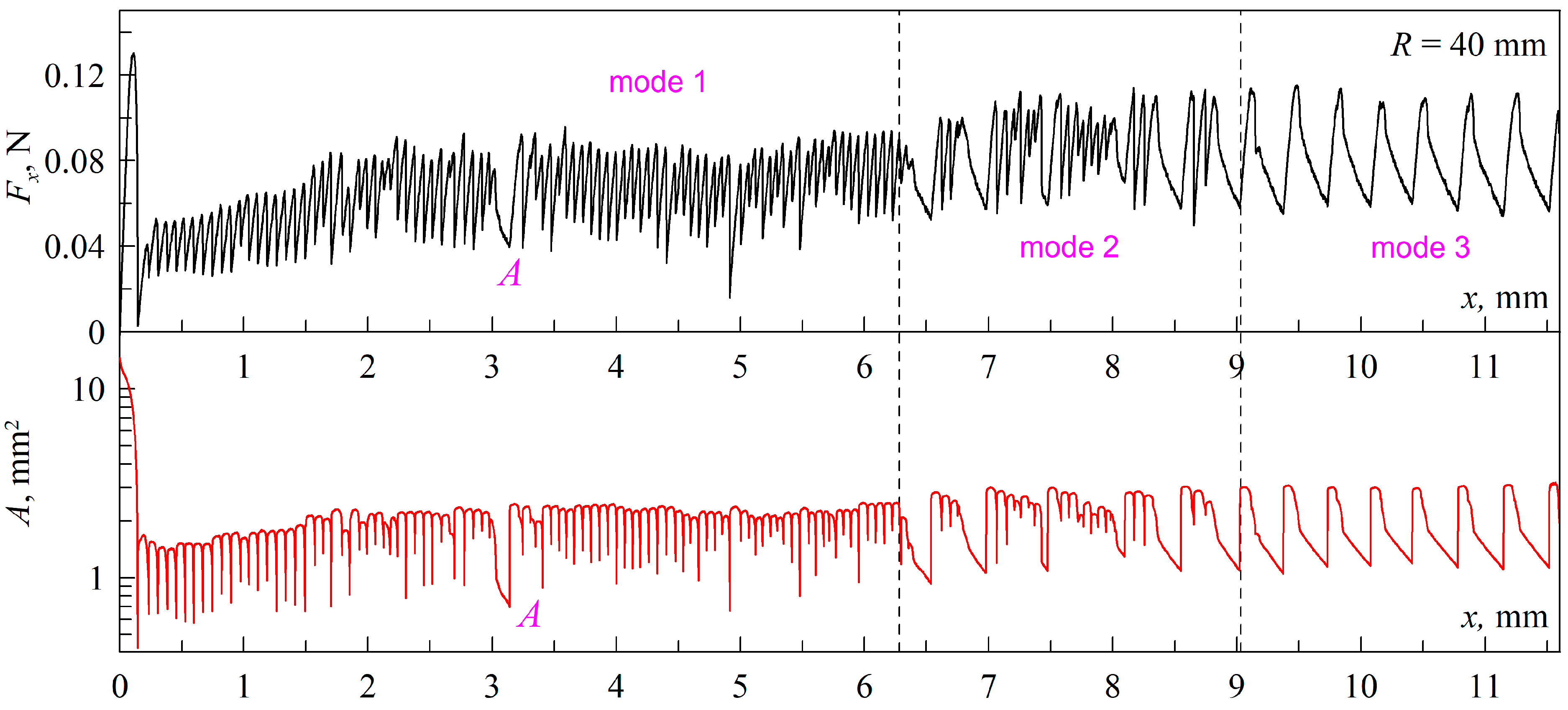
Figure 5 shows the transition between “mode 1” and “mode 3” discussed in this paper. However, in the experiments, we also found a transient regime between these two stationary friction regimes. We labeled this mode as “mode 2” and observed it in the experiment with an indenter of a larger radius R = 40 mm. Figure 8 shows the successive transitions between all three modes. Here, the transient mode “mode 2” is something between “mode 1” and “mode 3”, because in “mode 2” the system continuously transitions between the stick–slip (“mode 1”) and “mode 3”, in which there is no sudden reduction in tangential force due to global slippage of the rubber over the indenter surface. Note that here in “mode 1”, the transition to “mode 3” also takes place once in the dependency region, the vicinity of which is shown by point A. However, in general, “mode 1” remains stable up to the first vertical line, where it is replaced by “mode 2”, which in turn changes to the stable “mode 3” after the second vertical line.
The main difference observed between “mode 1” and “mode 3” is that in “mode 1” there are areas of abrupt reduction of friction force, while in “mode 3” there are no such areas. Therefore, the frequency of transitions between minimum and maximum values of tangential force in “mode 1” is much higher than the frequency of corresponding transitions in “mode 3”. It follows that the value of the transition frequency can be used as a parameter that will determine in which mode the system is currently operating.
One particular observation worth noting is depicted in Figure 8. Here, we observe a tendency for an increase in friction force and contact area with the displacement of the indenter. This occurs because the elastomer surface in a real experiment is always inclined at a slight angle to the path of the indenter, as it is not possible to perfectly orient them in parallel. In this scenario, with the indenter shift, the indentation depth d increases due to this inclination. In Figure 8, the effect of the inclination becomes visually noticeable because the distance traveled by the indenter in this experiment is much greater than in the experiments described above (see, for example, Figure 2).
Above, Figure 3b shows the dependencies of the normal force FN on the indentation depth d in the phase of pulling the indenter out of the elastomer volume, where the lower curve corresponds to the experiment, the data of which are shown in Figure 8. A second experiment was performed immediately after this experiment, and the upper curve in Figure 3b shows the normal force dependence in this experiment. From the comparison of the dependencies shown in Figure 3b, it follows that the adhesion force in the second experiment was significantly lower. Dependencies of friction force Fx and contact area A for the second experiment with indenter with a radius R = 40 mm are shown in Figure 9, from which it follows that here the stable “mode 3” was realized. This fact confirms the conclusions made above in the discussion of Figure 3a that the transition between “mode 1” and “mode 3” is caused by contamination of the indenter surface and a decrease in the specific work of adhesion.
For completeness of representation of the effect considered in this paper, we conducted an additional experiment with an indenter of an even larger radius R = 50 mm, the results of which confirm the conclusions above but do not introduce anything new; therefore, the data of this experiment are not included in the main text of the paper and are placed in the supplementary material (Figures S1–S3), which also contains videos of the experiment (Videos S6 and S7).

4. Conclusions

In this work, it has been shown experimentally that during friction of surfaces, between which there is a pronounced adhesive interaction, a transition between two different friction modes is observed. At the beginning of the motion, the system exhibits a stick–slip mode, in which global slippage of the rubber over the indenter surface occurs when the friction force and tangential stresses reach maximum values. As a result of this slippage, the friction force and stresses decrease dramatically and must again reach their maximum values for the next act of slippage. As the indenter moves further, another steady-state mode is established in which there is no sudden global slip of the rubber over the indenter. In this second mode, a stationary sliding region exists at the trailing edge of the contact where slip is realized at a velocity similar to the shear rate of the indenter. The tangential stresses in this region always take the maximum value corresponding to the rubber sliding. The presence of a region of stationary sliding leads to the fact that a sudden decrease in friction force becomes impossible. During friction in such a regime, there are acts of periodic discontinuous contact propagation at the front edge when new elastomer regions, which are initially unloaded in the tangential direction, come into contact. At further friction, there is a simultaneous loading of newly adhered rubber regions and their gradual withdrawal from the contact, which leads to a complex form of dependencies of friction force and contact area on the indenter shear. When the contact is narrowed down to the smallest size of the region in which steady-state sliding is always realized, contact spreads again. This mechanism leads to a significant reduction in the frequency of transitions between maximum and minimum values of friction force compared to the stick–slip mode. The first stick–slip mode is realized only briefly for a fresh, recently treated indenter surface. Experiments with indenters of different radii (30, 40, and 50 mm) indicate that the transition from stick–slip to another mode of friction occurs due to contamination of the indenter surface during its interaction with the elastomer. Despite the existence of a large number of papers on the study of adhesive tangential contact, we have not found such a transition effect between friction modes in the literature. Therefore, the proposed work is innovative and important from a fundamental point of view for a better understanding of the processes occurring in the contact between rubbing surfaces between which adhesive interaction is strongly pronounced.

Supplementary Materials

The following supporting information can be downloaded at: https://www.mdpi.com/article/10.3390/lubricants12040110/s1, Video S1: A spherical indenter with a radius R = 30 mm was immersed to a depth of dmax = 0.2 mm with a velocity of v = 1 μm/s into a layer of TANAC CRG N3005 elastomer with a thickness of h = 5 mm. After reaching the maximum depth, the indenter was pulled, with the same velocity, out of the rubber layer to a zero level where, in theory, the indentation should be d0 = 0 mm. But, because of backlash of the motor, the indentation depth is about d0 = 6 μm. After reaching the “zero” level, the indenter was moved in the tangential direction with a velocity of v = 1 μm/s. The video shows the first experiment conducted with the freshly machined indenter with a radius R = 30 mm. Separate panels in the video show the time dependencies of the normal (FN) and tangential (Fx) forces, the contact area (A), and the average tangential stress (<τ> = Fx/A). In addition, the lower left panel shows the evolution of the contact zone; it also shows the current values of the indentation depth (d), the tangential shift of the indenter (x), and the time (t) that has passed since the beginning of the indentation. The video relates to the first panels of Figure 2, Figure 4, and Figure 5 in the article. Video S2: It is similar to the Video S1 experiment, but with one difference, as, in this case, the indenter has already been contaminated after the first experiment. The video relates to the second panels of Figure 2 and Figure 4 in the article. Video S3: It is similar to the Video S2 experiment. The video relates to the third panels of Figure 2 and Figure 4 in the article. Video S4: It is similar to the Video S1 experiment, but for an indenter with a bigger radius of R = 40 mm; the tangential displacement of the indenter is also bigger. The video relates to Figure 8 in the article. Video S5: It is similar to the Video S4 experiment, but in this case, the indenter has already been contaminated after the first experiment. The video relates to Figure 9 in the article. Video S6: It is similar to the Video S4 experiment, but the indenter has a bigger radius of R = 50 mm. The video relates to Figure S1 in the supplementary material. Video S7: It is similar to the Video S6 experiment, with the difference that the indenter is now contaminated after the first experiment. The video relates to Figure S2 in the supplementary material. Figure S1: Dependencies of the tangential force (Fx) (top panel) and contact area (A) (bottom panel) on tangential shift of the indenter (x) in the first experiment with the indenter with a radius R = 50 mm. Supplementary Video S6 is also available (presented data are similar to dependencies obtained with indenter R = 40 mm that are shown in Figure 8 in the main article). Figure S2: Dependencies of the tangential force (Fx) (top panel) and contact area (A) (bottom panel) on tangential shift of the indenter (x) in the second experiment with the indenter with a radius R = 50 mm. Supplementary Video S7 is also available (presented data are similar to dependencies obtained with indenter R = 40 mm that are shown in Figure 9 in the main article). Figure S3: Dependencies of the normal force (FN) on indentation depth (d) in the first and second experiments with an indenter with a radius R = 50 mm. Supplementary Videos S6 and S7 are also available (presented data are similar to dependencies obtained with indenter R = 40 mm that are shown in Figure 3b in the main article).

Author Contributions

Conceptualization, scientific supervision, project administration, writing—review and editing, V.L.P.; methodology, software, hardware, conducting of experiments, experimental data analysis and interpretation, validation, writing—original draft preparation, I.A.L.; software, experimental data analysis, visualization (supplementary videos), writing—original draft preparation, T.H.P. All authors have read and agreed to the published version of the manuscript.

Funding

This research was funded by Deutsche Forschungsgemeinschaft (Project DFG PO 810-55-3).

Institutional Review Board Statement

Not applicable.

Informed Consent Statement

Not applicable.

Data Availability Statement

The datasets generated for this study are available upon request from the corresponding authors.

Conflicts of Interest

The authors declare no conflicts of interest.

References

  1. Zheng, B.; Tang, J.; Chen, J.; Zhao, R.; Huang, X. Investigation of Adhesion Properties of Tire—Asphalt Pavement Interface Considering Hydrodynamic Lubrication Action of Water Film on Road Surface. Materials 2022, 15, 4173. [Google Scholar] [CrossRef] [PubMed]
  2. Al-Assi, M.; Kassem, E. Evaluation of Adhesion and Hysteresis Friction of Rubber–Pavement System. Appl. Sci. 2017, 7, 1029. [Google Scholar] [CrossRef]
  3. Nishi, A.; Wakasugi, Y.; Watanabe, K. Design of a robot capable of moving on a vertical wall. Adv. Robot. 1986, 1, 33–45. [Google Scholar] [CrossRef]
  4. Fang, G.; Cheng, J. Advances in Climbing Robots for Vertical Structures in the Past Decade: A Review. Biomimetics 2023, 8, 47. [Google Scholar] [CrossRef] [PubMed]
  5. Autumn, K.; Liang, Y.A.; Hsieh, S.T.; Zesch, W.; Chan, W.P.; Kenny, T.W.; Fearing, R.; Full, R.J. Adhesive force of a single gecko foot-hair. Nature 2000, 405, 681–685. [Google Scholar] [CrossRef]
  6. Federle, W.; Labonte, D. Dynamic biological adhesion: Mechanisms for controlling attachment during locomotion. Philos. Trans. R. Soc. 2019, 374, 20190199. [Google Scholar] [CrossRef] [PubMed]
  7. Daltorio, K.A.; Gorb, S.; Peressadko, A.; Horchler, A.D.; Ritzmann, R.E.; Quinn, R.D. A Robot that Climbs Walls using Mi-cro-structured Polymer Feet. In Climbing and Walking Robots; Tokhi, M.O., Virk, G.S., Hossain, M.A., Eds.; Springer: Berlin/Heidelberg, Germany, 2006; pp. 131–138. [Google Scholar] [CrossRef]
  8. Greenwood, J.A.; Johnson, K.L. The mechanics of adhesion of viscoelastic solids. Philos. Mag. A 1981, 43, 697–711. [Google Scholar] [CrossRef]
  9. Maugis, D.; Barquins, M. Fracture mechanics and the adherence of viscoelastic bodies. J. Phys. D Appl. Phys. 1978, 11, 1989–2023. [Google Scholar] [CrossRef]
  10. Lin, Y.; Hui, C.Y. Mechanics of contact and adhesion between viscoelastic spheres: An analysis of hysteresis during loading and unloading. J. Polym. Sci. Part B Polym. Phys. 2002, 40, 772–793. [Google Scholar] [CrossRef]
  11. Pérez-Ràfols, F.; Nicola, L. Incipient sliding of adhesive contacts. Friction 2021, 10, 963–976. [Google Scholar] [CrossRef]
  12. Savkoor, A.R.; Briggs, G. The effect of tangential force on contact of elastic solids in adhesion. Proc. R. Soc. Lond. A Math. Phys. Sci. 1977, 356, 103–114. Available online: https://www.jstor.org/stable/79410 (accessed on 20 March 2024).
  13. Sahli, R.; Pallares, G.; Papangelo, A.; Ciavarella, M.; Ducottet, C.; Ponthus, N.; Scheibert, J. Shear-Induced Anisotropy in Rough Elastomer Contact. Phys. Rev. Lett. 2019, 122, 214301. [Google Scholar] [CrossRef] [PubMed]
  14. Mergel, J.C.; Sahli, R.; Scheibert, J.; Sauer, R.A. Continuum contact models for coupled adhesion and friction. J. Adhes. 2019, 95, 1101–1133. [Google Scholar] [CrossRef]
  15. Sahli, R.; Pallares, G.; Ducottet, C.; Ben Ali, I.E.; Al Akhrass, S.; Guibert, M.; Scheibert, J. Evolution of real contact area under shear and the value of static friction of soft materials. Proc. Natl. Acad. Sci. USA 2018, 115, 471–476. [Google Scholar] [CrossRef] [PubMed]
  16. Shen, L.; Glassmaker, N.J.; Jagota, A.; Hui, C.-Y. Strongly enhanced static friction using a film-terminated fibrillar interface. Soft Matter 2008, 4, 618–625. [Google Scholar] [CrossRef] [PubMed]
  17. Das, D.; Chasiotis, I. Sliding of adhesive nanoscale polymer contacts. J. Mech. Phys. Solids 2020, 140, 103931. [Google Scholar] [CrossRef]
  18. Waters, J.F.; Guduru, P.R. Mode-mixity-dependent adhesive contact of a sphere on a plane surface. Proc. R. Soc. A 2010, 466, 1303–1325. [Google Scholar] [CrossRef]
  19. Lyashenko, I.A.; Popov, V.L.; Pohrt, R.; Borysiuk, V. High-Precision Tribometer for Studies of Adhesive Contacts. Sensors 2023, 23, 456. [Google Scholar] [CrossRef] [PubMed]
  20. Electronic Resource: Innovation Company TANAC Co., Ltd. Available online: https://www.k-tanac.co.jp/crystalnone (accessed on 20 March 2024).
  21. Lyashenko, I.A.; Popov, V.L.; Borysiuk, V. Experimental Verification of the Boundary Element Method for Adhesive Contacts of a Coated Elastic Half-Space. Lubricants 2023, 11, 84. [Google Scholar] [CrossRef]
  22. Morishita, M.; Kobayashi, M.; Yamaguchi, T.; Doi, M. Observation of spatio-temporal structure in stick–slip motion of an adhesive gel sheet. J. Physics Condens. Matter 2010, 22, 365104. [Google Scholar] [CrossRef]
  23. Lyashenko, I.A.; Pham, T.H.; Popov, V.L. Effect of Indentation Depth on Friction Coefficient in Adhesive Contacts: Experiment and Simulation. Biomimetics 2024, 9, 52. [Google Scholar] [CrossRef] [PubMed]
  24. Yamaguchi, T.; Ohmata, S.; Doi, M. Regular to chaotic transition of stick–slip motion in sliding friction of an adhesive gel-sheet. J. Phys. Condens. Matter 2009, 21, 205105. [Google Scholar] [CrossRef] [PubMed]
  25. Brochard-Wyart, F.; de Gennes, P.-G. Naive model for stick-slip processes. Eur. Phys. J. E 2007, 23, 439–444. [Google Scholar] [CrossRef] [PubMed]
  26. Filippov, A.E.; Klafter, J.; Urbakh, M. Friction through Dynamical Formation and Rupture of Molecular Bonds. Phys. Rev. Lett. 2004, 92, 135503. [Google Scholar] [CrossRef] [PubMed]
  27. Berman, A.D.; Ducker, W.A.; Israelachvili, J.N. Origin and Characterization of Different Stick−Slip Friction Mechanisms. Langmuir 1996, 12, 4559–4563. [Google Scholar] [CrossRef]
  28. Yan, C.; Chen, H.-Y.; Lai, P.-Y.; Tong, P. Statistical laws of stick-slip friction at mesoscale. Nat. Commun. 2023, 14, 6221. [Google Scholar] [CrossRef] [PubMed]
  29. Khudoynazarov, K. Longitudinal-Radial Vibrations of a Viscoelastic Cylindrical Three-Layer Structure. Facta Univ. Ser. Mech. Eng. 2024. online first. [Google Scholar] [CrossRef]
  30. Carbone, G.; Mandriota, C.; Menga, N. Theory of viscoelastic adhesion and friction. Extreme Mech. Lett. 2022, 56, 101877. [Google Scholar] [CrossRef]
  31. Popov, V.L.; Li, Q.; Lyashenko, I.A.; Pohrt, R. Adhesion and friction in hard and soft contacts: Theory and experiment. Friction 2021, 9, 1688–1706. [Google Scholar] [CrossRef]
  32. Lyashenko, I.A.; Filippov, A.E.; Popov, V.L. Friction in Adhesive Contacts: Experiment and Simulation. Machines 2023, 11, 583. [Google Scholar] [CrossRef]
  33. Argatov, I.I.; Lyashenko, I.A.; Popov, V.L. Adhesive sliding with a nominal point contact: Postpredictive analysis. Int. J. Eng. Sci. 2024. accepted. [Google Scholar]
  34. Yoshizawa, H.; Israelachvili, J. Fundamental mechanisms of interfacial friction. 2. Stick-slip friction of spherical and chain molecules. J. Phys. Chem. 1993, 97, 11300–11313. [Google Scholar] [CrossRef]
  35. Jäger, J. Axi-symmetric bodies of equal material in contact under torsion or shift. Arch. Appl. Mech. 1995, 65, 478–487. [Google Scholar] [CrossRef]
  36. Papangelo, A. On the Effect of Shear Loading Rate on Contact Area Shrinking in Adhesive Soft Contacts. Tribol. Lett. 2021, 69, 48. [Google Scholar] [CrossRef]
  37. Mergel, J.C.; Scheibert, J.; Sauer, R.A. Contact with coupled adhesion and friction: Computational framework, applications, and new insights. J. Mech. Phys. Solids 2021, 146, 104194. [Google Scholar] [CrossRef]
Figure 1. Real photo of the contact area between the spherical steel indenter (1) and the elastomer (2) illuminated by a surrounding LED (3). Contact forces are measured with the force sensor (4).
Lubricants 12 00110 g001
Figure 2. Dependencies of the friction force Fx on the tangential displacement x of the indenter in three consecutive experiments (panels from top to bottom) for an indenter with a radius R = 30 mm. A supplementary video (Video S1) is available for the figure.
Lubricants 12 00110 g002
Figure 3. Dependencies of the normal force FN on the indentation depth d corresponding to the pulling phase of the steel indenters from the CRG N3005 elastomer: (a) the results of three experiments with an indenter with a radius R = 30 mm are shown; (b) the results of two experiments with an indenter with a radius R = 40 mm are shown.
Lubricants 12 00110 g003
Figure 4. Dependencies of the contact area A on the indenter coordinate x corresponding to three consecutive experiments, the data of which are shown in Figure 2, for an indenter with a radius R = 30 mm. Supplementary videos (Videos S1–S3) are available for the figure.
Lubricants 12 00110 g004
Figure 5. Dependencies on the tangential displacement of the indenter x: friction force Fx (a), contact area A (b), coordinates of the front and back contact boundaries (c), and average value of tangential stresses τ = Fx/A (d). All dependencies correspond to the first experiment, the results of which are shown in Figure 2 and Figure 4. A supplementary video (Video S1) is available for the figure.
Lubricants 12 00110 g005
Figure 6. Top row of figures: photographs of the contact areas corresponding to points (1–7) shown in Figure 5. Bottom row: the same photographs as in the top row, but where colors show the differences between adjacent contact areas; blue shows the area that has come out of contact and red shows the area that has come into contact (except for the first figure “1”, which is the same as in the top panel). For example, figure “2–1” shows the difference between the contact configurations “2” and “1” on the top panel, figure “3–2” shows the difference between the contact areas in figures “3” and “2”, etc. A supplementary video (Video S1) is available for the figure.
Lubricants 12 00110 g006
Figure 7. Top row of figures: photographs of the contact areas corresponding to points (a–h) shown in Figure 5. Bottom row: the same photographs as in the top row, but where colors show the differences between the contact areas, where blue shows the area that came out of contact and red shows the area that came into contact (except for the first panel “a”, which coincides with the corresponding image in the top panel). For example, figure “b–a” shows the difference between figures “b” and “a” on the top panel, figure “c–b” shows the difference between the contact areas in figures “c” and “b”, etc. A supplementary video (Video S1) is available for the figure.
Lubricants 12 00110 g007
Figure 8. (Top panel) Dependence of friction force Fx on the indenter tangential displacement x, corresponding to the experiment with an indenter with a radius R = 40 mm; (Bottom panel) Corresponding dependence of the contact area A on the displacement x. A supplementary video (Video S4) is available for the figure.
Lubricants 12 00110 g008
Figure 9. (Top panel) Dependencies of the friction force Fx on the indenter tangential displacement x, corresponding to the experiment with an indenter with a radius R = 40 mm; (Bottom panel) Corresponding dependence of the contact area A on the displacement x. Both dependencies correspond to the second experiment, which was performed immediately after the first experiment, the results of which are shown in Figure 8. Supplementary videos (Videos S4 and S5) are available for the figure.
Lubricants 12 00110 g009
Disclaimer/Publisher’s Note: The statements, opinions and data contained in all publications are solely those of the individual author(s) and contributor(s) and not of MDPI and/or the editor(s). MDPI and/or the editor(s) disclaim responsibility for any injury to people or property resulting from any ideas, methods, instructions or products referred to in the content.

