Article

The Utilization of a Damping Structure in the Development of Self-Adaptive Water-Lubricated Stern Bearings

1
College of Nuclear Science and Technology, Naval University of Engineering, Wuhan 430033, China
2
Science and Technology on Thermal Energy and Power Laboratory, Wuhan Second Ship Design and Research Institute, Wuhan 430205, China
3
School of Mechanics and Aerospace Engineering, Dalian University of Technology, Dalian 116024, China
4
State Key Laboratory of Structural Analysis, Optimization and CAE Software for Industrial Equipment, Dalian University of Technology, Dalian 116024, China
*
Authors to whom correspondence should be addressed.
Lubricants 2024, 12(2), 32; https://doi.org/10.3390/lubricants12020032
Submission received: 25 November 2023 / Revised: 19 January 2024 / Accepted: 21 January 2024 / Published: 24 January 2024
(This article belongs to the Special Issue Tribological Research on Transmission Systems)

Abstract

:
A novel water-lubricated stern bearing damping structure with self-adaptive performance is proposed to meet the load-balancing and vibration-damping requirements of water-lubricated bearings. This innovative damping structure comprises an elastic element and a damping alloy layer. The elastic element facilitates the static and dynamic load sharing of the stern bearing, mitigates the edge effects, ensures even distribution of the contact pressure along the axial direction, and enhances the overall bearing performance. Consequently, it prolongs the service life of the bearing and minimizes friction-induced stimulation. The damping alloy layer effectively attenuates the transmission of shafting vibrations to the foundation through the bearing, optimizing the vibration transmission characteristics. Leveraging the finite element model, an in-depth analysis of the compensation capability of the turning angle and damping performance of the adaptive stern bearing was conducted. The findings reveal that when the thickness of the elastic element is increased from 10 mm to 40 mm, the maximum contact pressure can be reduced by 12.53%. When the length ratio of the elastic element is reduced from 0.7 to 0.4, the maximum contact pressure is reduced by 12.42%. Therefore, increasing the thickness and decreasing the length of the elastic element in the adaptive damping device enhance the load performance, improve the compensation capabilities, and reduce the bearing wear, thereby promoting greater bearing uniformity. Furthermore, the adaptive vibration-damping device optimizes the vibration transmission characteristics from the propeller stimulation to the bearing node. The computational results demonstrate a noteworthy reduction in the speed, acceleration, and displacement responses at the first-order natural frequency, decreasing by 58.82%, 58.90%, and 58.86%, respectively. This substantial reduction in the vibration response at the first-order natural frequency signifies the effective mitigation of vibrations in the system.

1. Introduction

Propulsion shafting is an important part of a marine power plant [1,2,3]. Its primary function is to convert the power generated by diesel or electrical engines into thrust, which propels the marine vehicles forward. The propulsion system is a complex system that consists of several integral components, including the engine, mechanical coupling, shafting, thrust bearing, stern bearing, and propeller. The shafting plays a vital role in the propulsion system by serving as the connective link between the screw propeller and the engine, facilitating the transmission of rotational power. However, it often generates vibrations due to the operation of the engine, the rotation of the propeller, and the main shaft itself. These vibrations are transmitted to the stern hull through the bearing and the base and ultimately transmitted to the water to produce noise [4]. In addition, excessive vibration may lead to the failure of propulsion shafting components, including stern bearings, which greatly reduces the reliability of the equipment [5,6]. Therefore, it is essential to carefully design the propulsion system to minimize vibrations and noise levels, ensuring optimal performance and prolonging the lifespan of the marine vehicles.
The transverse support of propulsion shafting, provided by the stern bearing, is the primary mode of transmission for propeller excitation force from the shafting to the hull [7]. Consequently, the stern bearing emerges as a critical piece of equipment that significantly impacts the acoustic performance of the propulsion system and the acoustic radiation of the hull stern [8,9]. Therefore, it is imperative to consider the design and functionality of the stern bearing to mitigate any adverse effects on the overall performance and acoustics of the marine vehicle.
The uneven distribution of loads applied to the stern bearing, which varies during operation, poses a significant challenge for its proper design. The stern bearing bears the weight of the propulsion system’s shaft and also undergoes substantial biasing of the cantilever load from the propeller. This uneven load distribution on the bearing introduces edge-loading effects, whereby the load concentrates predominantly on the edge nearest to the propeller of the stern bearing, while the bow-stern bearing experiences minimal or even zero load [10]. This edge-loading effect can potentially cause severe issues for the stern bearing, as local overloads expedite wear on the bearing, thereby reducing its service life. Furthermore, the partial wear of bearings is related to the misalignment and shock vibration of the shafting [11,12,13]. The bearing brush may also wear under local overload conditions, generating friction noise. In a long-term running test on a journal bearing conducted by Sander et al. [14], it was observed that under unevenly distributed load conditions, even though the bearing primarily operated in pure hydrodynamic conditions, the edges of the bearing exhibited severe wear at the conclusion of the test. Consequently, enhancing the supporting interface characteristics of the stern bearing and minimizing the influence of edge-loading effects constitute essential research topics in the design of stern bearings.
Extensive research has been dedicated to optimizing the friction and vibration states of water-lubricated bearings. Bhushan conducted an experimental study to investigate the noise generation mechanism in water-lubricated rubber bearings, thereby shedding light on the underlying causes of this phenomenon [15]. Krauter simulated the actual operating conditions of ship water-lubricated bearings in seawater to the fullest extent possible and performed a comprehensive simulation test study on the friction noise of water-lubricated rubber bearings [16]. This pioneering study comprehensively examined the impact of various physical parameters on the vibration of the bearing system. Yao et al. delved into the complexities of the mechanism of vibration and noise generation in water-lubricated rubber bearings, experimentally analyzing the influence of bearing parameters and other related factors on noise generation [17]. Employing a finite element analysis, Zhou et al. investigated the influence of different structural parameters on the friction noise of water-lubricated rubber bearings [18]. Collectively, these aforementioned research studies demonstrate that the friction noise generated by water-lubricated rubber bearings under low speed and heavy load conditions is intimately connected to the friction system comprising the shaft and bearing components. These findings have profound implications for the design and optimization of water-lubricated bearings.
The vibration-damping capabilities of water-lubricated stern bearings, which serve as the primary conduit for transverse vibration transmission, are currently a focal point of research. Extensive investigations have been undertaken to augment the lubrication and vibration-damping performances of these bearings. Qin et al. have developed a novel material for ship liner water-lubricated bearings, which exhibits improved vibration-damping properties [19]. In their study, nitrile butadiene rubber was utilized as the matrix, and UHMWPE and graphite were incorporated to facilitate the blending modification. Furthermore, Qin’s thesis study analyzed the influence of the coupling effect between the friction force of these water-lubricated rubber bearings and the unbalanced load of the propeller mass on the vibration characteristics of the propeller shafting [20]. This analysis was grounded in well-established friction and shafting dynamics models of water-lubricated rubber bearings.
Wang et al. devised a compensation method for the deformation caused by the off-loading of ship stern bearings, thereby augmenting their bearing capacity [21]. Ouyang et al. innovated a damping-type water-lubricated bearing structure and validated its efficacy in mitigating vibrational performance through experimental verification [22]. Xie et al. formulated fluid–structure interaction dynamic models for the bearing system and methodically examined the influence of multi-coupling factors pertaining to lubrication parameters [23]. Ma et al. examined the utilization of damping alloys in water-lubricated bearing systems, revealing that this material considerably diminishes the vibration response at the first-order fixed frequency [24]. He et al. delved deeper into the application of elastic elements in the stern bearing design, discovering that the amalgamation of damping alloys and magnetic water compounds can enhance the vibration transmission characteristics of bearings [25,26].
A damping alloy exhibits excellent vibration-damping characteristics, holding vast application prospects in the field of vibration damping [27]. In recent years, scholars have extensively studied the materials of the damping alloy. Alaneme et al. [28] investigated the mechanical properties and damping properties of the Cu-32Zn-10Sn-xNi alloy. Their findings revealed that the mechanical properties and damping properties of the Cu-32Zn-10Sn-XNi alloy achieved an optimal balance when the Ni content was at 0.4 wt %. Xiao et al. [29] developed a high-strength Fe-Mn damping alloy as a substitute for conventional gear materials, which could absorb the energy from vibration sources. Through simulation and experimental verification, it was demonstrated that the high-strength Fe-Mn damping alloy exhibited a vibration-damping effect. Ma et al. [30] fabricated a novel high-damping Mg-1.5Gd-1Zn alloy using the traditional hot extrusion methodology. This alloy showcased commendable strength, ductility, and damping properties. Kam et al. [31] utilized the additive manufacturing method to produce composite sleeve bearings with diverse filling structures and scrutinized their damping capacity. The results indicated that the compressed bearing significantly influenced the stability of the rotating shaft system, and the damping capacity of the composite sleeve bearings varied considerably depending on their filling structures and occupancy rates. Fang et al. [32] proposed a new shape memory alloy (SMA) cable-constrained high-damping rubber (SMA-HDR) bearing. They conducted experimental research on full-size SMA-HDR bearing specimens and demonstrated their practicality in bridge engineering cases. The findings revealed that the application of the novel SMA-HDR bearing could notably reduce shock effects, particularly during earthquakes.
This paper presents an adaptive vibration-damping device specifically tailored for water-lubricated bearings, combining the acoustic performance and load-balancing capabilities. The vibration isolation design of the stern bearing is proposed that integrates the demands of load balancing and vibration reduction. The proposed device is designed to meet the specific damping requirements of water-lubricated stern bearings, exhibiting dynamic angular adaptability and effectively mitigating transverse vibrations. Through this innovative approach, the device offers a promising solution to managing coupling vibrations in ship propulsion shafting systems. The design of the adaptive vibration-damping device holds immense potential in elevating the overall performance and reliability of water-lubricated bearings in marine applications.

2. Adaptive Vibration-Damping Structure Design

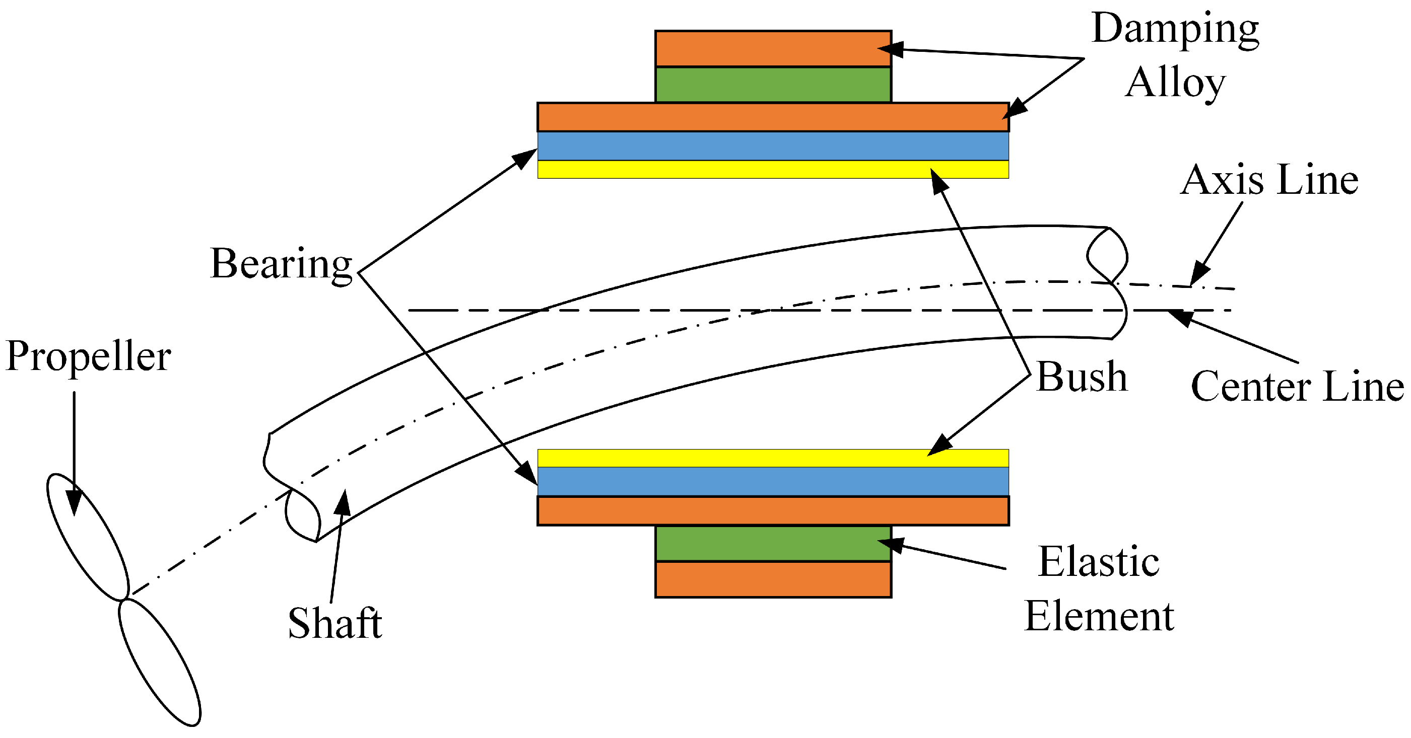
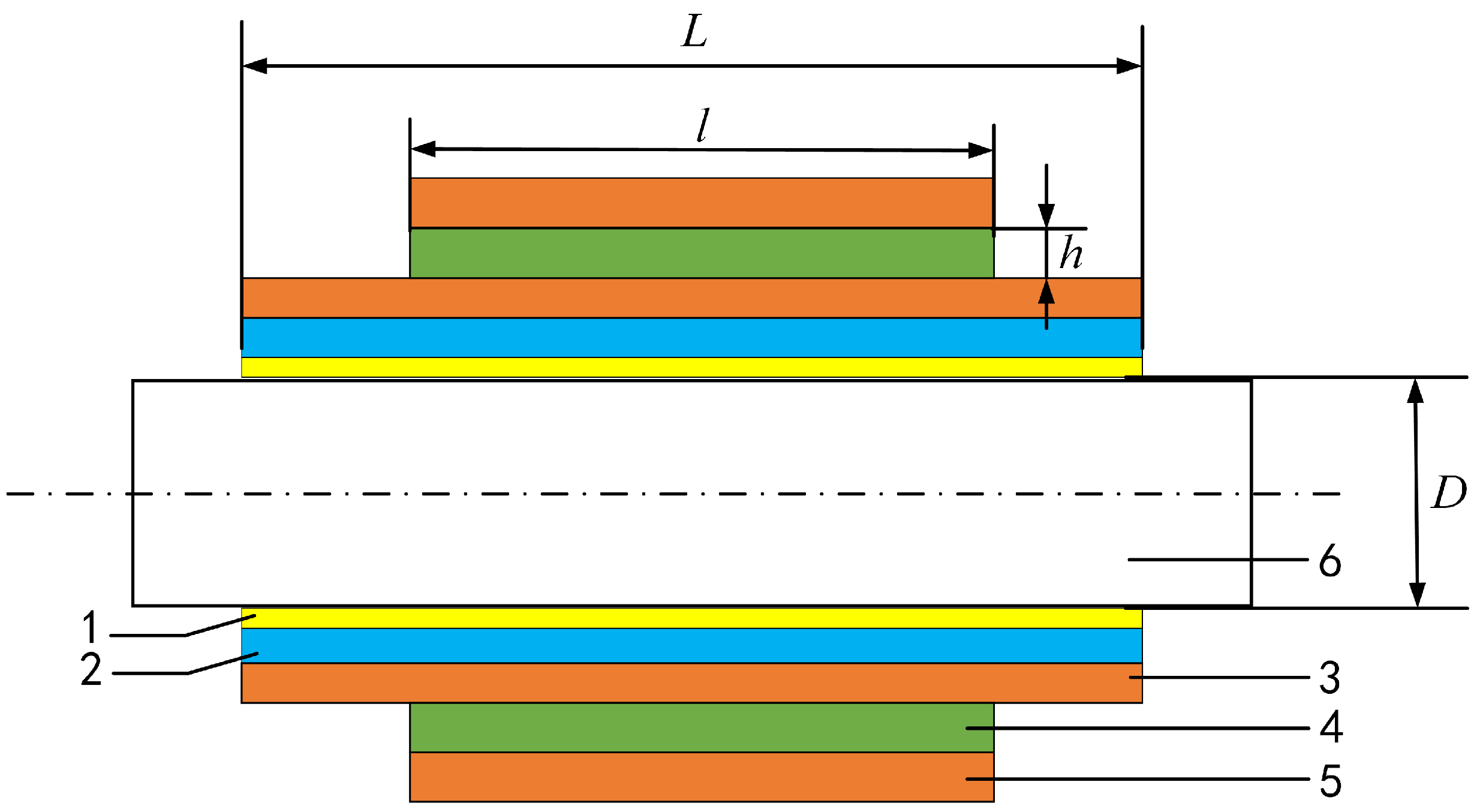
2.1. Structure Design

Adaptive Damping Structure

In the actual operation of a ship’s propulsion shafting, the cantilever support structure formed by the propulsion shafting and stern bearing causes the main shaft to deflect under the weight of the thruster. This deflection results in an inclination angle between the axis line and the bearing center line, as depicted in Figure 1. Consequently, the actual bearing area of the water-lubricated stern bearing becomes significantly smaller than the nominal bearing area, leading to pronounced edge effects. The high partial specific pressure on the stern bearing makes it difficult to establish effective liquid film lubrication, exacerbating bearing wear and even causing abnormal vibrations.
To improve the load uniformity of stern bearings, the shipbuilding standard recommends inclining the shaft hub for boring and installing stern bearings to accommodate the deflection angle of the main shaft. However, because the deflection of the main shaft changes dynamically during operation, inclining the stern bearings alone cannot completely resolve the issue of uneven bearing loads.
As shown in Figure 1, the device comprises elastic elements and damping alloy layers. The elastic elements facilitate the static and dynamic load balancing of the stern bearing, reducing the edge effects and ensuring even distribution of the contact pressure along the axis. This improvement increases the bearing’s service life and lessens friction-induced excitations. The damping alloy attenuates the transmission of vibrations from the shafting through the bearing to the foundation, optimizing vibration transmission characteristics.
To aid in the description of the damping structure, the components are designated with numbers. As shown in Figure 2, component 1 is the bush, component 2 is the bearing, component 3 is the internal damping alloy, component 4 is the elastic element, component 5 is the external damping alloy, and component 6 is the shaft. The geometric parameter L is the length of the bearing, l is the length of the adaptive device, and h is the thickness of the elastic element. By introducing the weight of the thruster as an input load to the stern end of the shafting model, this study elicited the influence of various geometric parameters on the performance of an adaptive stern bearing damping device. This performance included the contact pressure distribution and deformation of the stern bearing, the stress distribution of the adaptive damping device, and the angle of the stern end of the shafting.

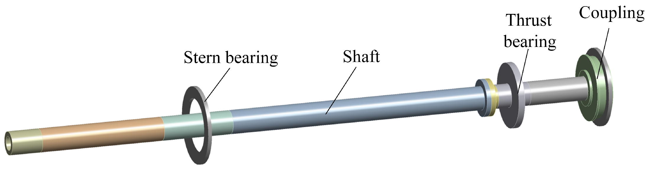
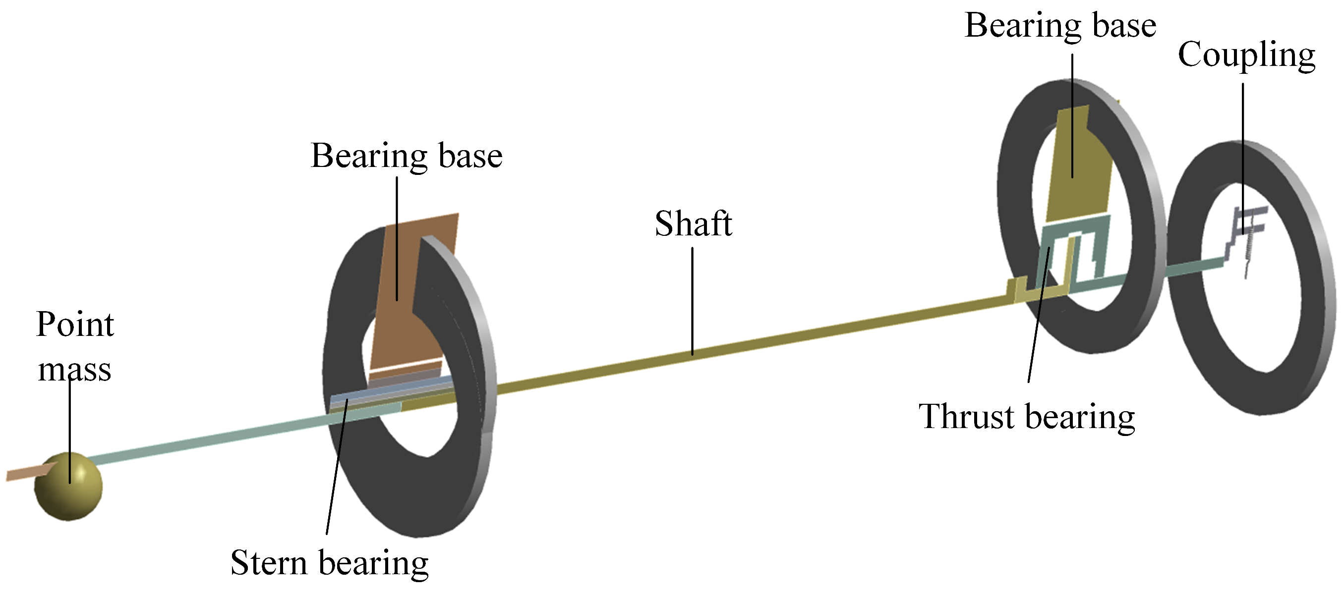
2.2. Configuration of Propulsion System

The propulsion shafting derives its power from the propulsion motor, which is then transmitted to the propeller via several components: the elastic coupling, thrust bearing, transmission shaft, and stern bearing. Figure 3 illustrates the configuration of the propulsion shafting equipped with an adaptive vibration-damping device. In contrast, Figure 4 exhibits the configuration of the propulsion shafting utilizing a traditional design. The sole difference is that the adaptive damping device is not utilized within the traditional design.

3. Static Performance Analysis

In order to investigate the dynamic angle compensation capabilities of the adaptive vibration-damping device structure, a study was conducted on the static load performance of the structural parameters utilizing a finite element model. The analysis delved into the effects of the elastic element’s thickness and length on various factors, such as the maximum contact pressure of the bearing bush, the maximum deformation of the bearing bush, the maximum stress of the adaptive vibration-damping device, and the stern angle of the shafting.

3.1. Finite Element Simulation

3.1.1. Finite Element Model

A finite element simulation analysis was carried out through the Static Structural module in ANSYS Workbench, and the finite element model as shown in Figure 5 was established. This model comprised three integral components of the adaptive vibration-damping device and the bearing: the stern bearing, the elastic elements, and the damping alloy layers.
The materials utilized for the adaptive stern bearings are outlined in Table 1. The bearing load P was set to 30 kN, the bearing inner diameter D measured 150 mm, and the width L of the bearing bush was 450 mm. The elastic element, crucial for enabling dynamic adaptive angle compensation, was strategically placed at the center to enhance its angle compensation capabilities, as illustrated in Figure 2. The outer layer of the elastic element and damping alloy are designed to have the same thickness and length. Therefore, in the foregoing analysis, the thickness and width of the elastic element were chosen as the variables for the analysis of their influence.

3.1.2. Shafting Connection and Boundary Conditions

With the addition of global standard earth gravity, the propeller was simulated by the mass point, and the weight was set to 17,500 N. The outermost edge of the stern bearing and the outermost edge of the thrust bearing were connected to the hull through the bracket, and the fixed support was set. The friction contact was set between the stern shaft and stern bearing, and the friction coefficient was 0.02. The bearing bush, bearing body, damping alloy, and elastic element were set as common nodes to simulate the connection relationship. The spindle and the intermediate shaft were connected by a flange, and the binding contact was set here. The intermediate shaft flange was connected to one end of the coupling, and the binding contact was set here.

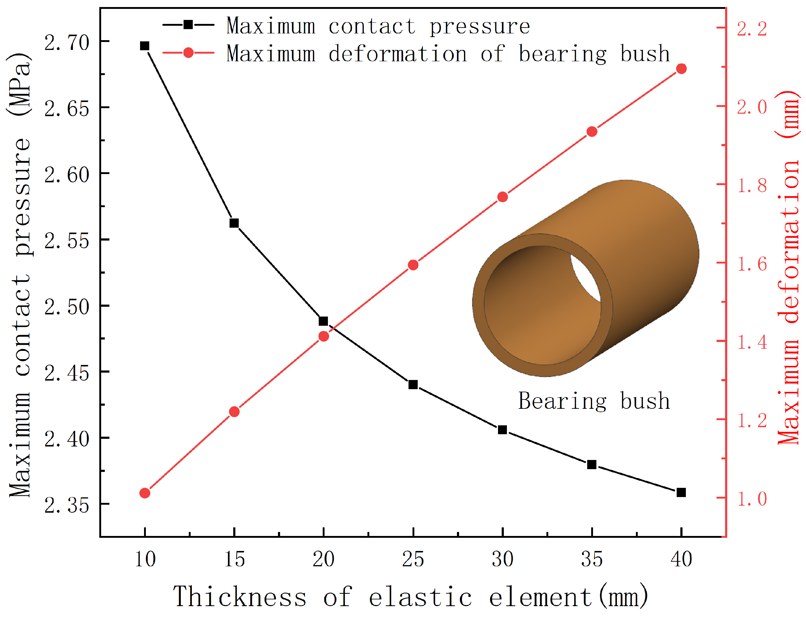
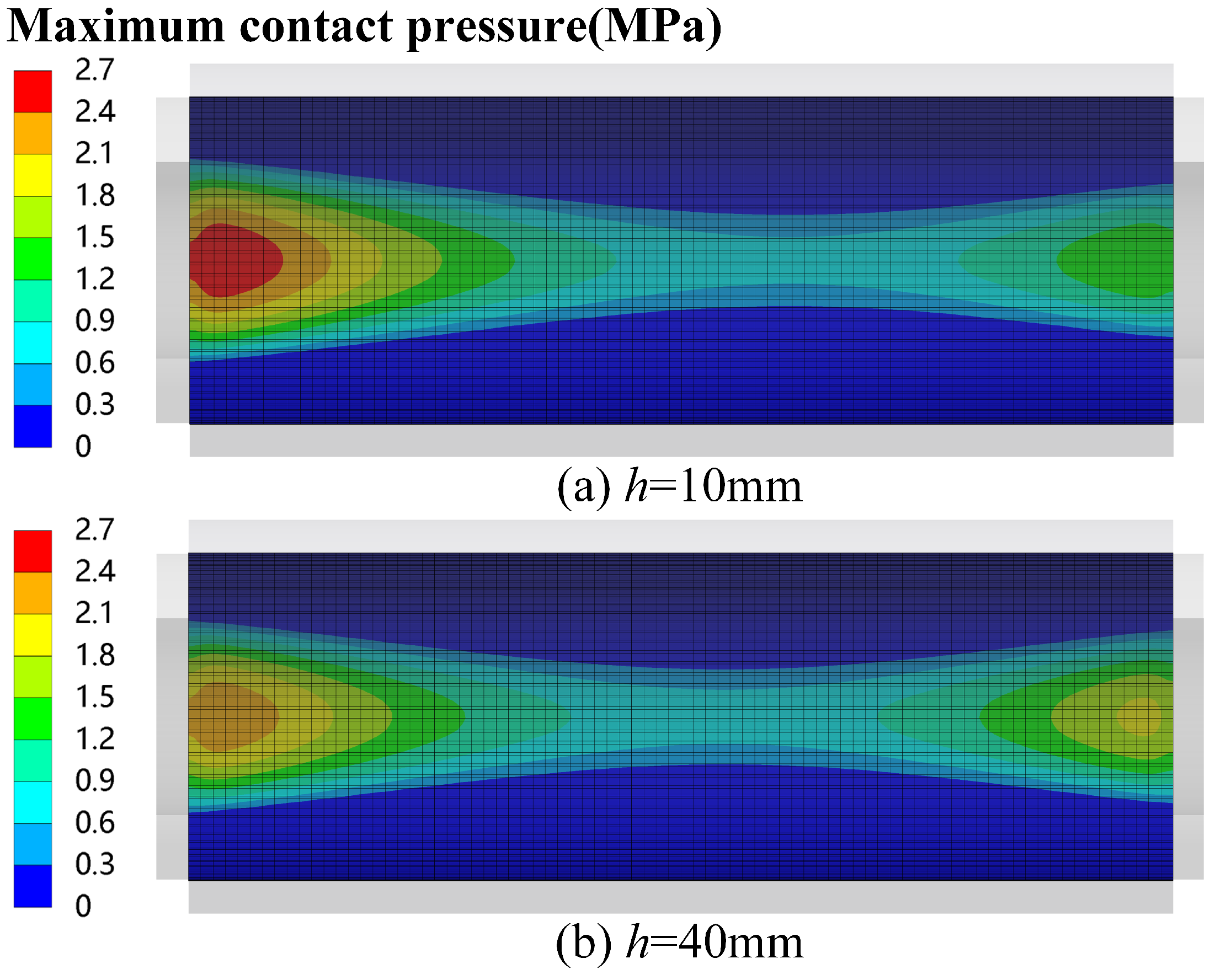
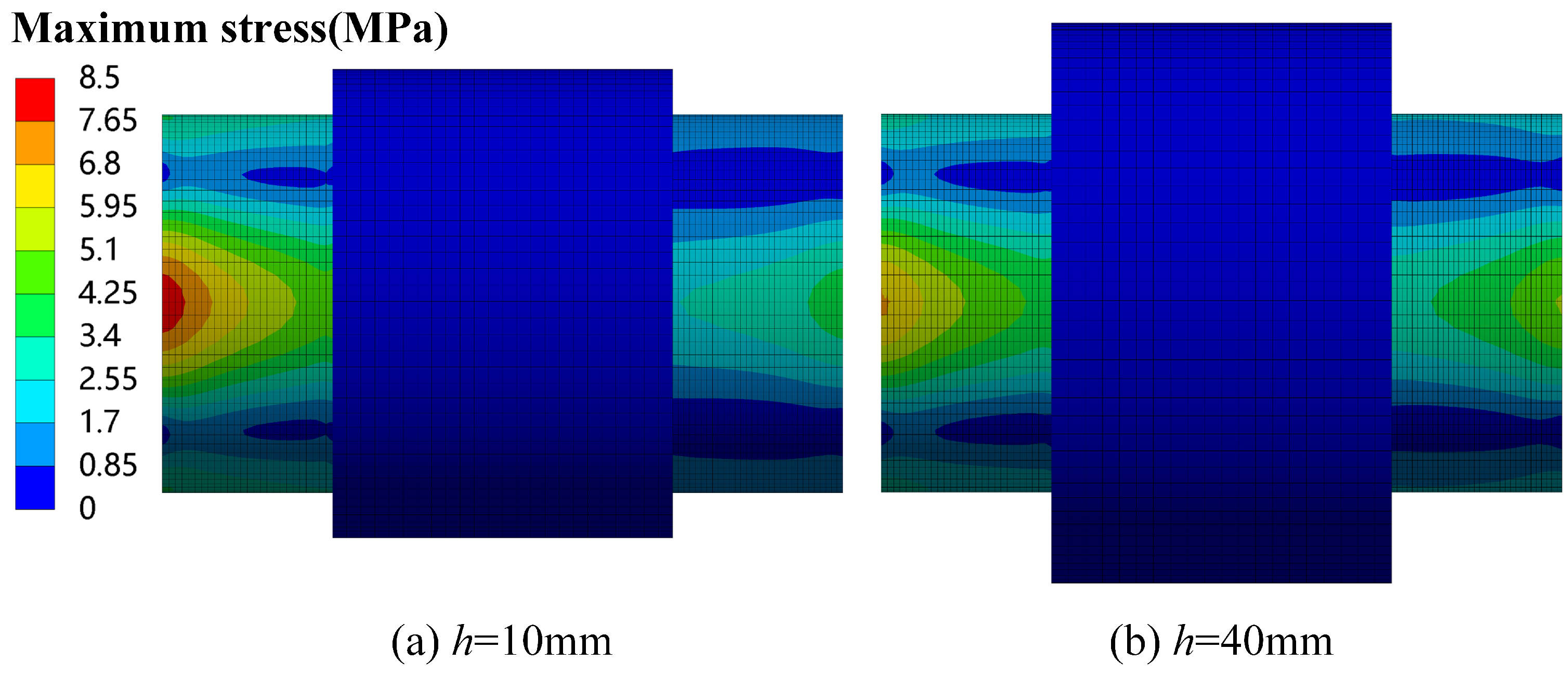
3.2. Influence of Thickness

The influence of the elastic element thickness on the performance of the damping structure was analyzed. The axial length of the elastic element was fixed and set to L / 2 . Figure 6 illustrates the impact of the elastic element’s thickness on both the contact pressure and deformation of the bearing bush.
An analysis of the diagram reveals that an increase in the thickness of the elastic element results in a decrease in the maximum contact pressure between the shaft and the bearing bush, accompanied by an increase in the deformation of the bearing bush. These findings demonstrate that increasing the thickness of the elastic element is beneficial for enhancing the angle compensation capabilities of the adaptive vibration reduction device, thereby improving the stern bearing’s load-bearing capacity and reducing the local maximum contact pressure on the bearing.
Figure 6 also shows that the deformation of the bush increases with the increment in the elastic element thickness. Large deformation of the bush will cause the rotation of the shaft and affect the dynamic performance of the propulsion system. Therefore, the impact of the thickness of the bearing bush has a two-sided nature. When selecting the thickness of the bearing bush, it is necessary to comprehensively analyze and select from the perspectives of bearing pressure and deformation.
Furthermore, Figure 7 presents a comparative analysis of the maximum contact pressure of the bearing bush when the elastic element’s thickness is set to 10 mm and 40 mm. When the thickness is 10 mm, the maximum contact pressure is recorded at 2.6963 MPa, whereas at a thickness of 40 mm the maximum contact pressure reduces to 2.3585 MPa. This comparative analysis indicates a reduction of 12.53 % in the maximum contact pressure of the bearing bush, highlighting the positive impact of increasing the elastic element’s thickness on reducing contact pressure. The specific pressure value of the bearing calculated according to the above parameters is about 0.44 MPa. Due to the edge effect, the maximum pressure of the bearing bush is much larger than the specific pressure.
The influence of the thickness of the elastic element on the maximum stress of the adaptive device and the rotation angle of the propeller stern end is shown in Figure 8. The axial length of the elastic element is L / 2 . It can be seen from the figure that with the increase in the thickness of the elastic element, the maximum stress of the adaptive device decreases, but the rotation angle of the propeller stern end increases. Figure 9 shows the stress nephogram of the adaptive device when the thickness of the elastic element is 10 mm and 40 mm. When the thickness of the elastic element is 10 mm, the maximum stress of the adaptive vibration-damping device is 8.2 MPa, and when the thickness of the elastic element is 40 mm, the maximum stress of the adaptive vibration-damping device is 6.95 MPa. This comparative analysis shows that the maximum stress is reduced by 15.23%. In the actual design, it is necessary to increase the thickness of the elastic element while ensuring that the rotation angle of the stern end remains within the allowable range. This will ensure the optimal performance and durability of the elastic element in the given application.
The results of this analysis provide valuable insights into the design and optimization of damping structures for load-bearing applications. By adjusting the thickness of the elastic element, we can achieve improved performance and load-bearing capacity while reducing the risk of local maximum contact pressure.

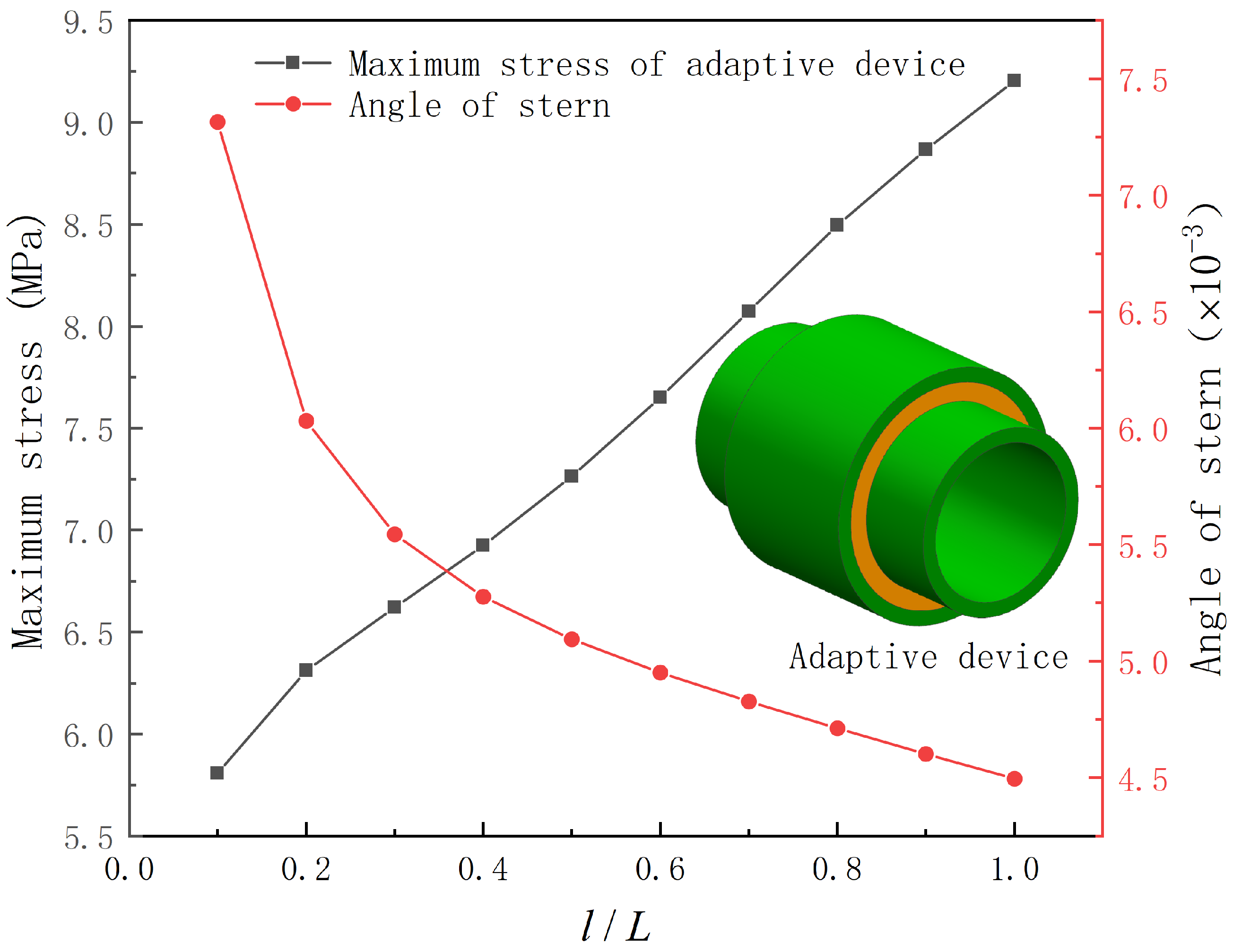
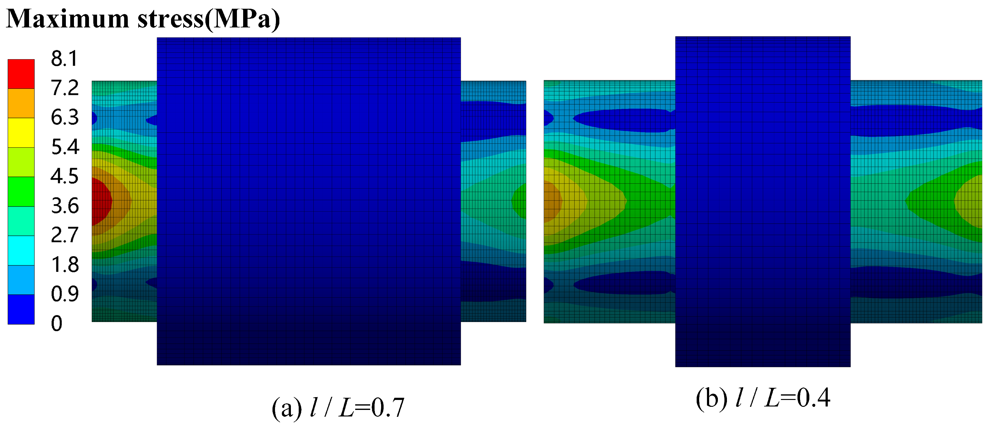
3.3. Influence of Length

The influence of the axial length of the elastic element on the maximum contact pressure of the stern bearing and the maximum deformation of the bearing bush was explored. The thickness of the elastic element was fixed as 25 mm. Considering the radial load demand imposed on the stern bearing, it is imperative that the axial length of the actual elastic element maintains a non-negligible magnitude. The primary focus of this study is confined to the examination of the mechanical properties of the stern bearing, thereby limiting the l / L value range to 0.1~1. The results, illustrated in Figure 10, elucidate the intricate relationship between the length-to-width ratio of the elastic element and pertinent bearing characteristics. As depicted in the diagram, an escalation in the ratio of the length of the elastic element to the width of the bearing corresponds to an augmentation in the maximum contact pressure exerted on the stern bearing. Concurrently, a diminution in the maximum deformation of the bearing bush is observed. This implies that a shorter elastic element is conducive to enhancing the angle compensation ability of the adaptive vibration reduction device, thereby ameliorating the partial load effect on the bearing.
Figure 11 provides a detailed analysis of the maximum contact pressure of the bearing for elastic element length ratios of 0.7 and 0.4 . Specifically, at l / L of 0.7 , the maximum contact pressure is registered at 2.6816 MPa. Conversely, when the l / L is reduced to 0.4 , the maximum contact pressure exhibits a commensurate decrease to 2.3485 MPa. Comparative scrutiny reveals a noteworthy reduction of 12.42 % in the maximum contact pressure of the bearing bush when transitioning from a ratio of 0.7 to 0.4 .
Then, we delved into the impact of the axial length of the elastic element on the maximum stress experienced by the adaptive device and the rotational angle of the propeller stern end, with the fixed thickness of the elastic element set to 25 mm. The findings, portrayed in Figure 12, elucidate a nuanced interplay between the length ratio of the elastic element to the stern bearing, the rotation angle of the propeller stern end, and the maximum stress incurred by the adaptive device.
Figure 12 underscores that an augmentation in the length ratio of the elastic element to the stern bearing results in a reduction in the rotation angle of the propeller stern end. However, this reduction is not without consequence, as the maximum stress experienced by the adaptive device concurrently increases. This intricate trade-off is further visualized in Figure 13, which presents stress contours for the adaptive device at length ratios of 0.7 and 0.4 .
At a length ratio of 0.7 , the adaptive vibration-damping device manifests a maximum stress of approximately 8.07 MPa. In contrast, at a reduced length ratio of 0.4 , the maximum stress diminishes to about 6.92 MPa. A comparative analysis reveals a noteworthy reduction of 14.23 % in the maximum stress experienced by the adaptive vibration-damping device when transitioning from a length ratio of 0.7 to 0.4 . Consequently, in practical design considerations, it is advisable to curtail the axial length of the elastic element while ensuring that the stern end rotation angle remains within permissible limits.

4. Vibration Reduction Performance Analysis
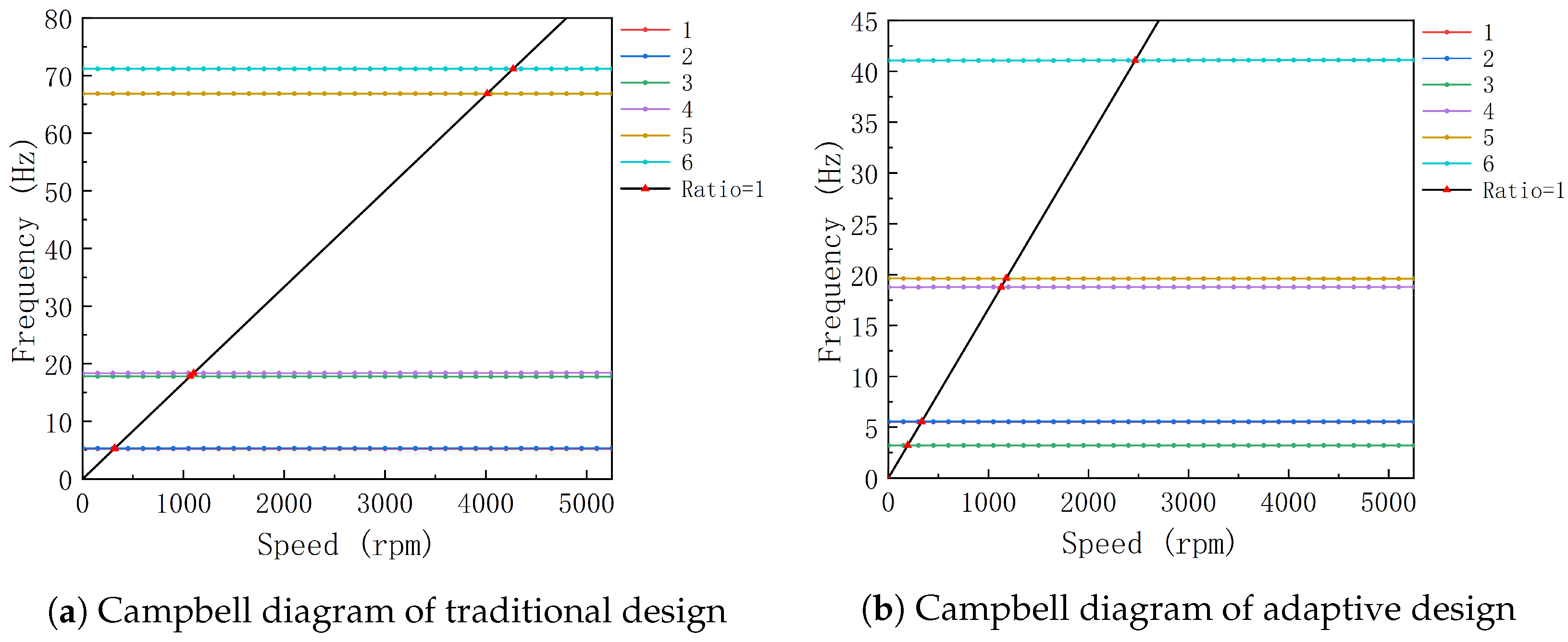
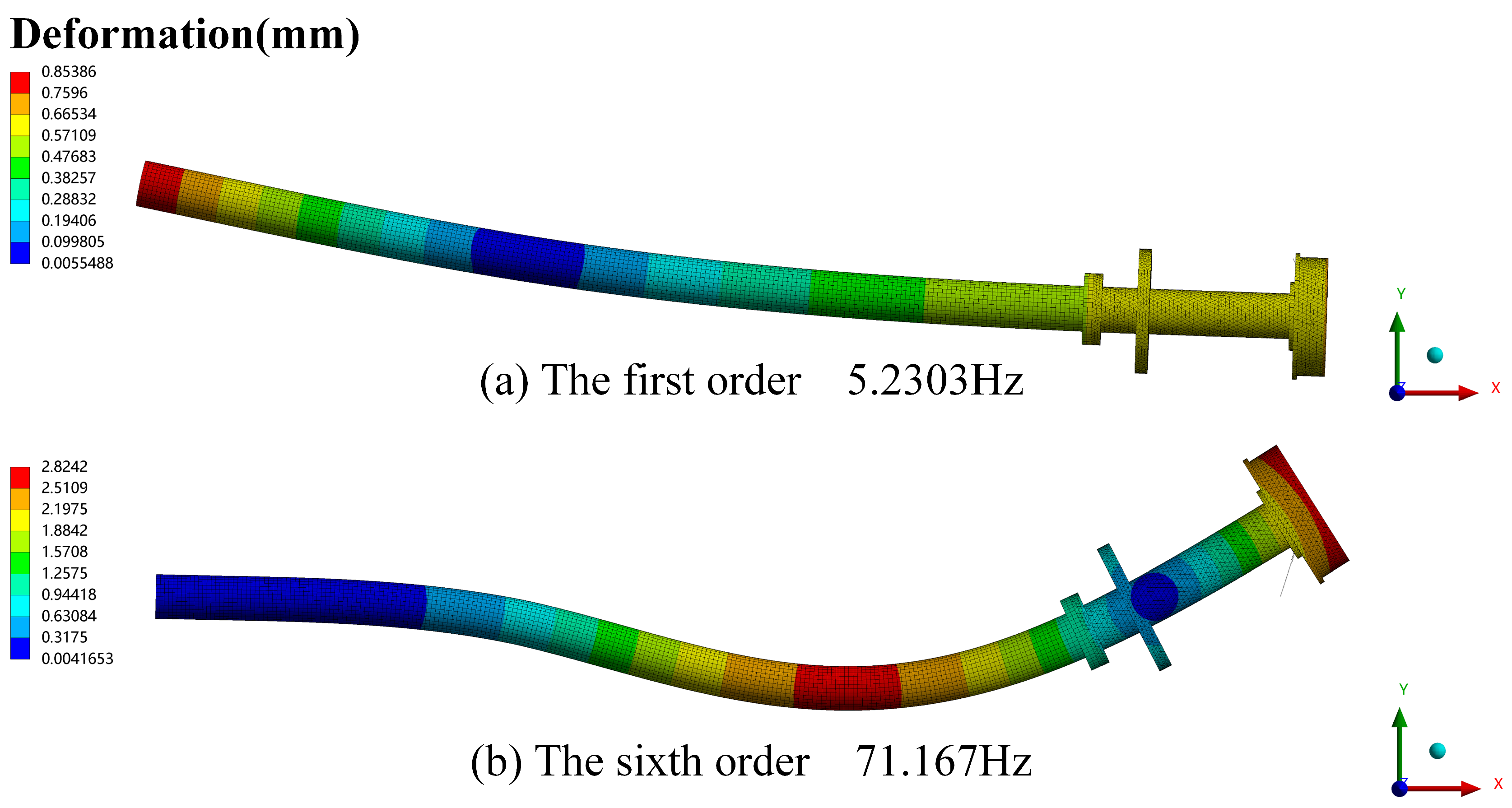
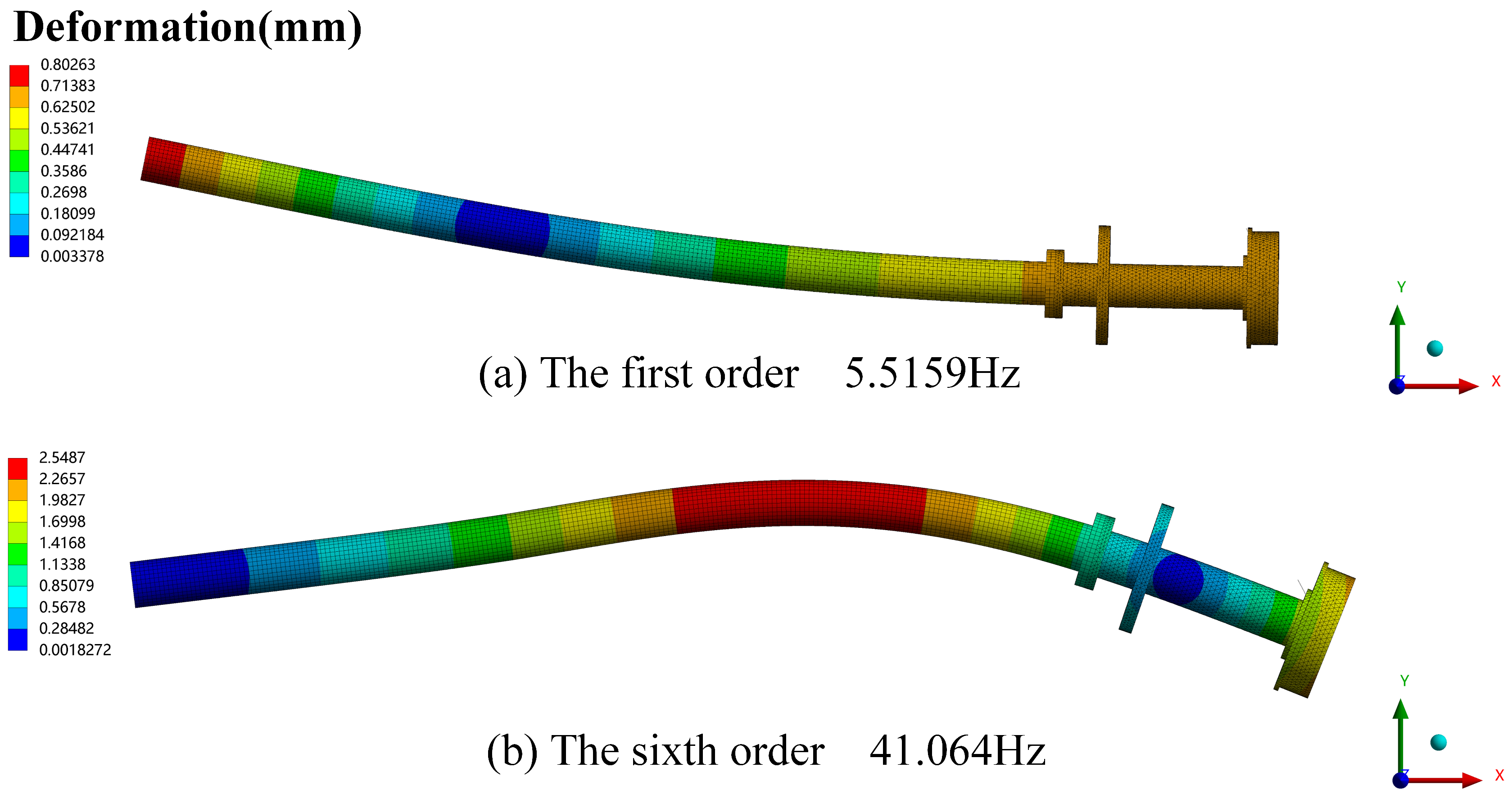
4.1. Modal Analysis

In the context of the shafting configuration delineated in Figure 3 and Figure 4, modal analyses were conducted for both the conventional design and the propulsion shafting featuring an adaptive vibration-damping device, with an elastic element length of 0.5 L and a thickness of 25 mm. The finite element model of the modal analysis was established, as shown in Figure 14. The investigation specifically centers on comprehending the impact of the adaptive vibration-damping device installed at the transom bearing on the dynamic characteristics of the shafting.
Primarily, this study scrutinized the influence of the self-adaptive vibration-damping device on the critical rotational vibration speed of the propulsion shafting. This analysis involved the generation of Campbell diagrams for both the propulsion shafting with the adaptive vibration-damping device and the conventional propulsion shafting, as illustrated in Figure 15a,b. The calculated critical speed results are detailed in Table 2.
The simulation of the rotor dynamics in this part used Modal in ANSYS Workbench for calculation. First, the model was processed, and only the rotor part was retained. The stiffness and damping coefficient were added to the stern bearing to simulate the bearing. The stiffness of the adaptive stern bearing was calculated according to the stiffness of the water film, stern bearing, damping alloy, and elastic element, and the main stiffness was about 1 × 10 7 N/m. The stiffness of the traditional stern bearing was only about 1 × 10 10 N/m with the water film and stern bearing in series. The thrust bearing was replaced by a grounded spring with a spring stiffness of 1.57 × 10 9 N/m. The radial extrusion stiffness of the coupling part was simulated by the bearing, the stiffness was set to 1 × 10 6 N/m, and the torsional stiffness was replaced by the spring, which is about 5.73 × 10 6 Nm/rad. A rotation speed from 0 to 3024 rpm was added and 20 points were set.
The findings elucidate that the adaptive vibration-damping device predominantly affects the critical speed at the first-order shaft frequency. Notably, the critical speed undergoes a discernible increase from 313.82 rpm to 330.97 rpm, constituting a 5.46 % enhancement. It is noteworthy that the adaptive vibration-damping device exhibits relatively minor influence on the first mode of the propulsion shafting.
Modal shapes resulting from the modal analyses of the traditional design and the adaptive design are presented in Figure 16 and Figure 17, respectively. These modal shapes offer a visual representation of the vibrational characteristics associated with each design, providing valuable insights into the dynamic behavior of the propulsion shafting with and without the incorporation of the adaptive vibration-damping device.

4.2. Harmonic Response Analysis

The harmonic response module in ANSYS Workbench was used for finite element simulation calculation. In order to speed up the calculation, the three-dimensional model was simplified into a two-dimensional model. The harmonic response analysis model of the adaptive tailshaft bearing is shown in Figure 18. The connection relationship of the shafting is similar to the modal analysis setup, except that the simulated bearings and springs of the stern bearings and thrust bearings are no longer grounded but are connected to the base, and the outer edge of the base is provided with a fixed support. The transverse unit excitation force was applied within the frequency range of 1~100 Hz at the thruster’s center of gravity. Subsequently, the vibration speed, acceleration, and displacement responses at the thruster bearing position were meticulously computed to assess the impact of the adaptive vibration-damping device on the vibration transmission characteristics from the thruster to the stern bearing. The comprehensive findings, as delineated in Figure 19, Figure 20 and Figure 21, offer a detailed insight into the transformative effects introduced by the adaptive vibration-damping structure.
An analysis of the vibration response at the stern bearing reveals predominant manifestations of the natural frequencies associated with first- and second-order cyclotron vibrations. The main results are listed in Table 3. Upon integration of the adaptive vibration-damping structure, a discernible reduction is observed in the speed response at the first natural frequency, diminishing from 5.78 × 10 4 mm/s to 2.38 × 10 4 mm/s, denoting a substantial decrease of 58.82 %. A commensurate trend is noted in the acceleration response, transitioning from 1.82 ×   10 2 mm / s 2 to 7.48 ×   10 3 mm / s 2 , marking a notable decline of 58.90 %. Concurrently, the displacement response exhibits a decrease from 1.84 ×   10 5 mm to 7.57 ×   10 6 mm, translating to a reduction of 58.86 %. This attenuation in displacement signifies a diminished transfer of the vibration energy to the foundation.
The results unequivocally establish the efficacy of the adaptive damping structure in substantially mitigating the transmission of vibration to the hull through the stern bearing, underscoring its potential as an effective mechanism for vibration control in thruster systems.
The vibration level difference is 20 times the common logarithm of the ratio of the effective value of the vibration response of the vibration source equipment to the effective value of the vibration response of the base.
D = 20 lg a 1 a 2
In the formula, D is the vibration level drop, a 1 is the vibration response value of the vibration source equipment, and a 2 is the vibration response value of the base.
This study employs the acceleration response derived from a harmonic response analysis as a pivotal metric for calculating the reduction in vibration levels, with the outcomes presented in Figure 22. The findings illuminate that, when subjected to a transverse unit force applied at the thruster’s center of gravity, the vibration level reduction exhibited by the shafting featuring an adaptive vibration-damping device surpasses that of the traditional design across the frequency spectrum of 1~100 Hz. This discernible disparity underscores the superior efficacy of the adaptive vibration-damping device in enhancing the damping effect on vibrations within this frequency range.

5. Discussion

The significance of model validation is very important. In this study, the experimental validation is not available at the present stage. A meticulous literature review revealed a scarcity of reports on the application of damping to stern bearings, with a dearth of experimental data from other authors. Consequently, to facilitate model verification, we resorted to consulting experimental data derived from research in alternative industrial applications where both numerical simulations and experimental analyses were employed to validate damping effects.
Xiao et al. [29] developed an Fe-Mn damping alloy, formulated a constitutive model for the alloy, and conducted research utilizing this novel material in lieu of conventional gear materials. The investigation encompassed both numerical simulations and vibration tests to affirm the damping efficacy of the developed high-strength Fe-Mn damping alloy. The experimental results are presented, revealing the impact of alloy materials on the damping effect of the gear box at various rotational speeds. An evaluation based on effective acceleration indicated noteworthy reductions in vibration amplitudes. At one measuring point, the effective acceleration values for both types of damping alloy materials at 700 rpm decreased by 11.0% and 21.8%, respectively. Likewise, at measuring point 6, reductions of 5.32% and 20.2% were observed at 700 rpm. These findings, though pertaining to damping alloy applications in gearboxes, substantiate the assertion that damping alloys can effectively mitigate vibration amplitudes, thereby demonstrating a pronounced damping effect.
Huang et al. [33] conducted experimental investigations to assess the performance of damping alloys. Specifically, the Fe-Mn damping alloy, Fe-Cr-Mo damping alloy, and 0.45C-steel were utilized to fabricate simple beams for the experimental validation of the damping alloy behavior. The amplitude–frequency response characteristics of the aforementioned materials were systematically compared through forced vibration tests employing a vibration measuring instrument. The study revealed that both the accelerated velocity and the resonance frequency range of the two damping alloys were markedly lower than those of 0.45C-steel. Notably, the damping properties of the Fe-Mn and Fe-Cr-Mo damping alloys surpassed those of 0.45C-steel under the given conditions.
These findings provide empirical evidence supporting the superior damping characteristics of damping alloys compared to conventional steel. The discernible reduction in both the accelerated velocity and resonance frequency range underscores the enhanced damping efficacy of the investigated alloys, thereby contributing valuable insights to the understanding of their vibration-damping capabilities.

6. Conclusions

In response to the damping requirements of water-lubricated stern bearings and considering the cantilever support characteristics inherent in propulsion shafting, this study proposes a novel self-adaptive vibration-damping device for water-lubricated stern bearings. This innovative design integrates the acoustic and load-balancing aspects of stern bearings. The static bearing performance and vibration-damping efficacy of this self-adaptive device were subjected to a detailed analysis, leading to the following conclusions:
  • The adaptive stern bearing vibration-damping device comprises elastic elements and damping alloy layers. Notably, augmenting the thickness and length of the elastic element and damping alloy serves to enhance the bearing load-balancing and angle compensation capabilities, thereby mitigating bearing wear.
  • The modal analysis calculations and comparative evaluations reveal a 5.46% increase in the first-order critical speed of the self-adaptive vibration-damping device for the propeller bearing shafting system in comparison to traditional shafting systems. Importantly, this adaptive device has minimal impact on critical speed.
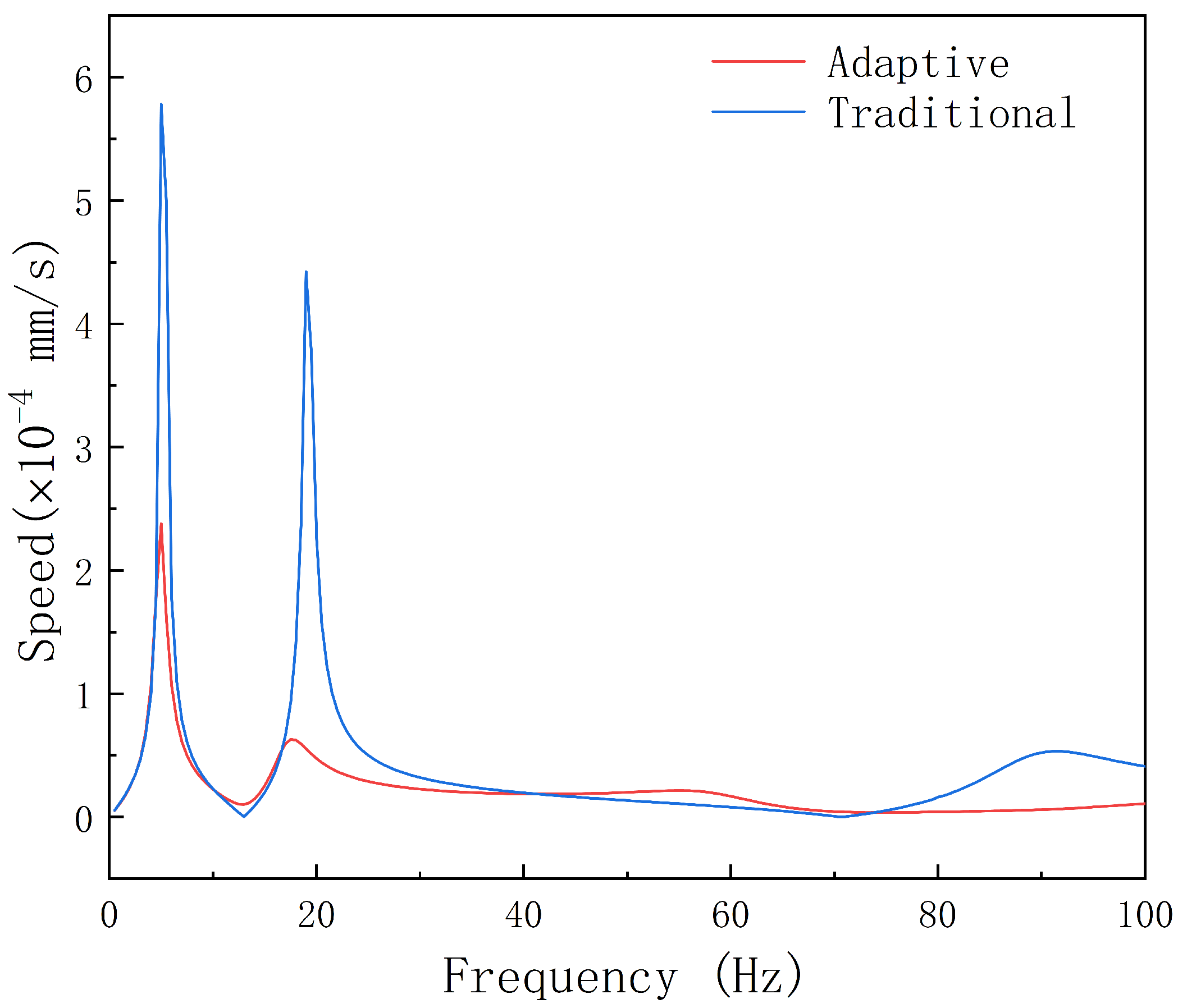
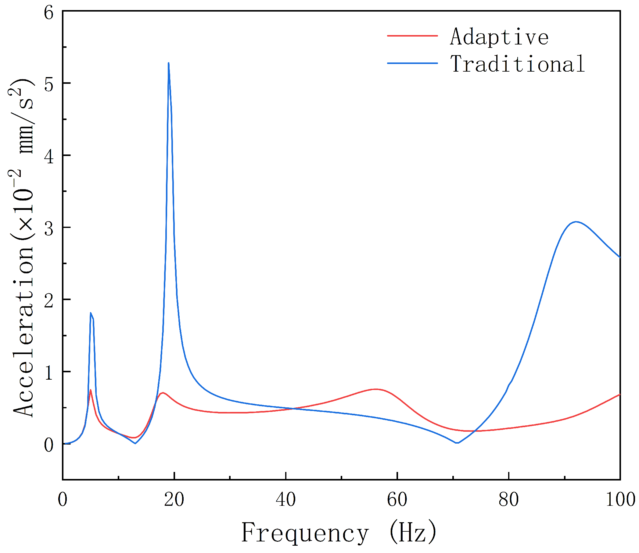
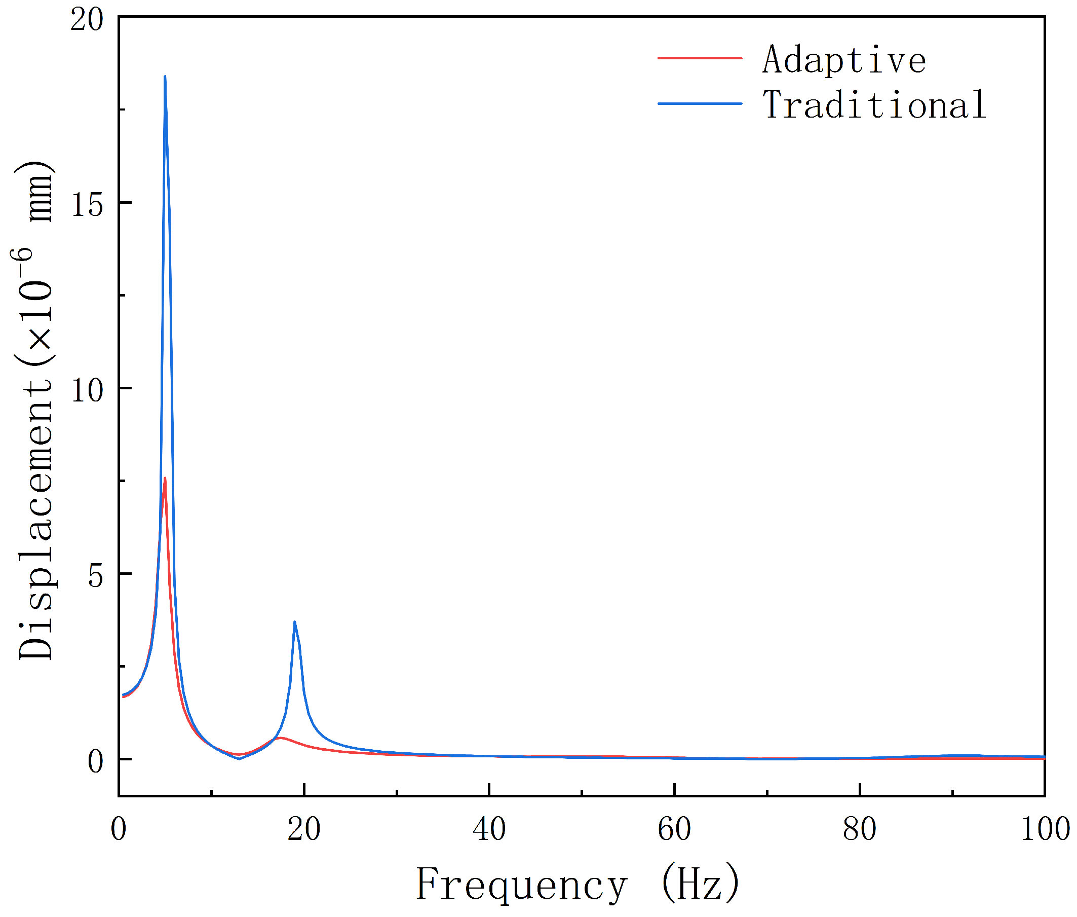
  • The in-depth comparative analyses highlight the primary influence of the self-adaptive vibration-damping device on the first-order shaft frequency. Adoption of this self-adaptive structure results in a substantial 58.82% reduction in the velocity response at the first-order natural frequency, a commensurate 58.90% reduction in the acceleration response, and a noteworthy 58.86% reduction in the displacement response. This collective reduction effectively curtails the transmission of vibrations to the hull through the stern bearing.
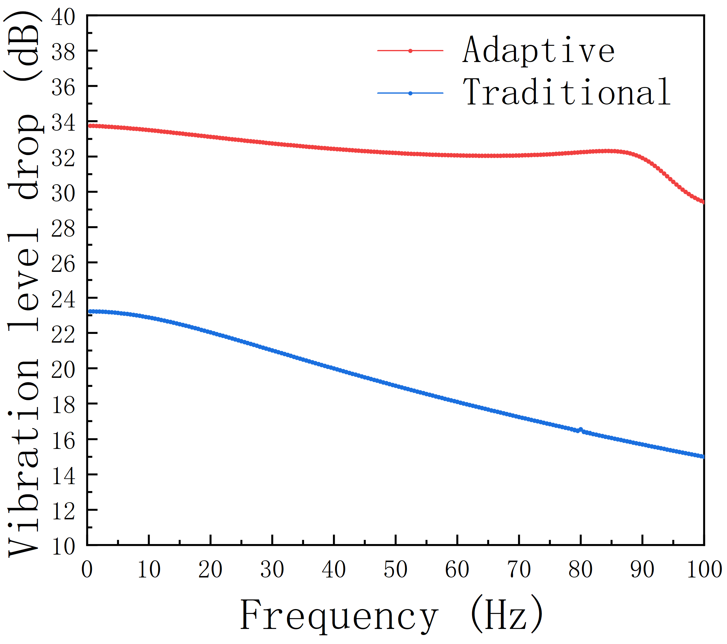
  • Further comparative analyses demonstrate a conspicuous increase in the vibration level drop of the adaptive vibration-damping device compared to traditional designs when subjected to a transverse unit force at the propeller’s center of gravity within the 1~100 Hz frequency range. This heightened effect underscores the increased efficacy of the vibration damping provided by the adaptive device.
In the current numerical simulation, a direct connection between the damping matrix of the stern bearing and the material properties of the damping alloy is not explicitly established. This lack of precision in calculating the damping matrix may lead to inaccurate simulation results. Future efforts will focus on a more thorough investigation of the damping properties of both the fluid and the bushing incorporating damping alloy, aiming for a more accurate representation of the system dynamics. Experimental validation of the proposed model will also be carried out.

Author Contributions

Conceptualization, T.H., Y.L. and Y.X.; methodology, Y.L., T.H. and Y.X.; software, Y.Z. and T.H.; validation, Y.Z. and Y.X.; investigation, T.H., Y.Z., Y.L. and Y.X.; resources, T.H. and Y.X.; data curation, Y.L. and Y.Z.; writing—original draft preparation, Y.L., Y.Z., T.H. and Y.X.; writing—review and editing, Y.L., Y.Z., T.H. and Y.X.; visualization, Y.Z. and Y.X.; supervision, Y.X.; project administration, T.H. and Y.X.; funding acquisition, T.H. and Y.X. All authors have read and agreed to the published version of the manuscript.

Funding

This research was funded by the National Natural Science Foundation of China (No. 12072065), the Open Fund of Science and Technology on Thermal Energy and Power Laboratory (No. TPL2022A01), and the Fundamental Research Funds for the Central Universities of China (No. DUT22YG119).

Data Availability Statement

Data available on request due to restrictions.

Conflicts of Interest

The authors declare no conflicts of interest.

References

  1. Liu, J.; Gu, Z.; Liu, S. Research on MDO of Ship Propulsion Shafting Dynamics Considering the Coupling Effect of a Propeller-Shafting-Hull System. Pol. Marit. Res. 2023, 30, 86–97. [Google Scholar] [CrossRef]
  2. Xing, P.; Lu, L.; Li, G.; Wang, X.; Gao, H.; Song, Y.; Zhang, H. A Multi-Method Approach to Identify the Natural Frequency of Ship Propulsion Shafting under the Running Condition. J. Mar. Sci. Eng. 2022, 10, 1432. [Google Scholar] [CrossRef]
  3. Lu, L.; Li, G.; Xing, P.; Gao, H.; Song, Y. A review of stochastic finite element and nonparametric modelling for ship propulsion shaft dynamic alignment. Ocean. Eng. 2023, 286, 115656. [Google Scholar] [CrossRef]
  4. Su, Z.; Zheng, Z.; Huang, X.; Hua, H. Research on dynamic vibration absorber with negative stiffness for controlling longitudinal vibration of propulsion shafting system. Ocean. Eng. 2022, 264, 112375. [Google Scholar] [CrossRef]
  5. Zhang, Z.; Duan, N.; Lin, C.; Hua, H. Coupled dynamic analysis of a heavily-loaded propulsion shafting system with continuous bearing-shaft friction. Int. J. Mech. Sci. 2020, 172, 105431. [Google Scholar] [CrossRef]
  6. Jose Legaz, M.; Amat, S.; Busquier, S. Marine Propulsion Shafting: A Study of Whirling Vibrations. J. Ship Res. 2021, 65, 55–61. [Google Scholar] [CrossRef]
  7. Jin, Y.; Lu, J.; Ouyang, W.; Liu, Z.; Lao, K. Vibration Reduction Performance of Damping-Enhanced Water-Lubricated Bearing Using Fluid-Saturated Perforated Slabs. Chin. J. Mech. Eng. 2020, 33, 92. [Google Scholar] [CrossRef]
  8. Xie, Z.; Jiao, J.; Yang, K.; Zhang, H. A state-of-art review on the water-lubricated bearing. Tribol. Int. 2023, 180, 108276. [Google Scholar] [CrossRef]
  9. Lai, G.J.; Jiang, Z.L.; Liu, J.L.; Ma, R.F.; Zeng, F.M. Influence of propeller hydrodynamic force on alignmentcharacteristics of a motor driving shafting system. J. Ship Mech. 2023, 27, 294–301. [Google Scholar]
  10. Boedo, S.; Booker, J.F. Classical Bearing Misalignment and Edge Loading: A Numerical Study of Limiting Cases. J. Tribol. 2004, 126, 535–541. [Google Scholar] [CrossRef]
  11. Peng, E.; Huang, R. Tribology investigation in marine rubber stern tube bearing with consideration of friction-induced vibration. Proc. Inst. Mech. Eng. Part-J. Eng. Tribol. 2016, 230, 376–388. [Google Scholar] [CrossRef]
  12. Kim, Y.G.; Kim, U.K. Design and analysis of the propulsion shafting system in a ship with single stern tube bearing. J. Mar. Sci. Technol. 2020, 25, 536–548. [Google Scholar] [CrossRef]
  13. Li, S.; Dong, C.; Yuan, C.; Bai, X. Effects of TiO2 nano-particles on wear-resistance and vibration-reduction properties of a polymer for water-lubricated bearing. Wear 2023, 522, 204713. [Google Scholar] [CrossRef]
  14. Sander, D.E.; Allmaier, H.; Priebsch, H.H.; Reich, F.M.; Witt, M.; Skiadas, A.; Knaus, O. Edge loading and running-in wear in dynamically loaded journal bearings. Tribol. Int. 2015, 92, 395–403. [Google Scholar] [CrossRef]
  15. Bhushan, B. Stick-Slip Induced Noise Generation in Water-Lubricated Compliant Rubber Bearings. J. Lubr. Technol. 1980, 102, 201–210. [Google Scholar] [CrossRef]
  16. Krauter, A.I. Generation of Squeal/Chatter in Water-Lubricated Elastomeric Bearings. J. Lubr. Technol. 1981, 103, 406–412. [Google Scholar] [CrossRef]
  17. Yao, S.; Yang, J.; Zhang, X.; Wang, J.; Rao, Z. Vibration and noise mechanism analysis and tests for water-lubrication rubber bearings. J. Vib. Shock 2011, 30, 214–216. [Google Scholar] [CrossRef]
  18. Zhou, Y.; Li, G.; Wang, J.X. Analysis of Frictional Noise for Water Lubricated Rubber Bearings System. Adv. Mater. Res. 2010, 156–157, 607–610. [Google Scholar] [CrossRef]
  19. Qin, H.; Zhou, X.; Yan, Z.; Liu, Z.; Zhao, X. Rubber/UHMWPE composites for stern tube bearings and its properties. Ordnance Mater. Sci. Eng. 2014, 37, 23–27. [Google Scholar] [CrossRef]
  20. Qin, W. Investigation on Friction Characteristics of the Water-Lubricated Rubber Bearings and the Induced Vibration of the Propeller Shafting Systems. Ph.D. Thesis, Shanghai Jiao Tong University, Shanghai, China, 2017. [Google Scholar]
  21. Wang, S.T.; Ou, Y.W.; Jin, Y.; Wang, L.; Deng, T.Y. Analysis of static characteristics of wave bearings considering elastic deformation. J. Ship Mech. 2020, 24, 1443–1541. [Google Scholar]
  22. Ouyang, W.; Yan, Q.; Kuang, J.; Jin, Y.; Peng, W. Simulation and experimental investigations on water-lubricated squeeze film damping stern bearing. J. Braz. Soc. Mech. Sci. Eng. 2021, 43, 54. [Google Scholar] [CrossRef]
  23. Xie, Z.; Jiao, J.; Wrona, S. The fluid-structure interaction lubrication performances of a novel bearing: Experimental and numerical study. Tribol. Int. 2023, 179, 108151. [Google Scholar] [CrossRef]
  24. Ma, J.; Liu, H.P.; Yang, H.; Dai, L.; He, T. Analysis of tribology and dynamics performance of self-adaptationwater-lubricated stern bearing. Ship Sci. Technol. 2022, 44, 66–70. [Google Scholar]
  25. He, T.; Xie, Z.; Tao, X.; Yang, K.; Jiao, J.; Huang, M.; Ma, W. Analysis of the Tribological and Dynamic Performance of the Self-Adapting Water-Lubricated Stern Bearing. Lubricants 2022, 10, 245. [Google Scholar] [CrossRef]
  26. He, T.; Wang, J.; Yao, S.W.; Shi, J.H.; Zhang, Q.C.; Xu, H.Z.; Zhao, B. Tribological and Dynamic Performances of Composite Water Lubricated Bearing with Magnetic Support. J. Propuls. Technol. 2022, 43, 200401. [Google Scholar] [CrossRef]
  27. Ji, X.; Chen, Y.; Liu, H.; Yu, H.; Wei, C.; Yan, Z. Experimental Investigation on the Vibration And Noise Characteristics of the Vibration Damping Alloy Material. In Proceedings of the ASME International Mechanical Engineering Congress And Exposition, Pittsburgh, PA, USA, 9–15 November 2018; Volume 11. [Google Scholar]
  28. Alaneme, K.K.; Ubah, T.J.; Aikulola, E.O. On the material characteristics of Ni modified Cu32Zn10Sn shape memory alloys: Mechanical and damping behaviour in consideration. Mater. Today-Proc. 2022, 62, S73–S78. [Google Scholar] [CrossRef]
  29. Xiao, P.; Yang, W.; Jiang, K.; Yang, J.; Shi, W. Study on Vibration Reduction Performance of Gear Pairs Made by a High-Strength Fe-Mn Damping Alloy. Appl. Sci. 2022, 12, 3925. [Google Scholar] [CrossRef]
  30. Ma, Y.; Liu, C.; Jiang, S.; Gao, Y.; Wan, Y.; Chen, Z. Tailoring good combinations among strength, ductility and damping capacity in a novel Mg-1.5Gd-1Zn damping alloy via hot extrusion. Mater. Sci. Eng.-Struct. Mater. Prop. Microstruct. Process. 2023, 871, 144827. [Google Scholar] [CrossRef]
  31. Kam, M.; Saruhan, H.; Ipekci, A. Experimental investigation of vibration damping capabilities of 3D printed metal/polymer composite sleeve bearings. J. Thermoplast. Compos. Mater. 2023, 36, 2505–2522. [Google Scholar] [CrossRef]
  32. Fang, C.; Liang, D.; Zheng, Y.; Lu, S. Seismic performance of bridges with novel SMA cable-restrained high damping rubber bearings against near-fault ground motions. Earthq. Eng. Struct. Dyn. 2022, 51, 44–65. [Google Scholar] [CrossRef]
  33. Huang, S.K.; Zhou, D.C.; Liu, J.H.; Teng, J.; Li, N. Amplitude Frequency Response Characteristics of Fe-based Damping Alloy Simple Beams under Forced Vibrations. Adv. Mater. Res. 2011, 328–330, 1072. [Google Scholar] [CrossRef]
Figure 1. Propulsive shafting cantilever support diagram.
Lubricants 12 00032 g001
Figure 2. The configuration of the adaptive damping structure. The elastic element and the damping alloy layer are arranged in the middle of the stern bearing structure. Component 1 is the bush, component 2 is the bearing, component 3 is the internal damping alloy, component 4 is the elastic element, component 5 is the external damping alloy, and component 6 is the shaft.
Lubricants 12 00032 g002
Figure 3. Configuration of propulsion system with adaptive vibration-damping device.
Lubricants 12 00032 g003
Figure 4. Configuration of traditional propulsion system.
Lubricants 12 00032 g004
Figure 5. Finite element model of static performance analysis of the propulsion system with adaptive shafting.
Lubricants 12 00032 g005
Figure 6. Influence of elastic element thickness on maximum contact pressure and deformation of bearing bush.
Lubricants 12 00032 g006
Figure 7. Maximum contact pressure when h = 10 mm and 40 mm.
Lubricants 12 00032 g007
Figure 8. Influence of elastic element thickness on maximum stress and stern angle of adaptive device.
Lubricants 12 00032 g008
Figure 9. Comparative analysis of the maximum contact pressure of the adaptive device when the elastic element’s thickness is set to 10 mm and 40 mm.
Lubricants 12 00032 g009
Figure 10. Influence of elastic element length.
Lubricants 12 00032 g010
Figure 11. Maximum contact pressure when l / L = 0.7 and 0.4.
Lubricants 12 00032 g011
Figure 12. Influence of length ratio of the elastic element on the rotation angle of the propeller stern end and the maximum stress incurred by the adaptive device.
Lubricants 12 00032 g012
Figure 13. Maximum stress of adaptive device when l / L = 0.7 and 0.4.
Lubricants 12 00032 g013
Figure 14. Modal analysis model.
Lubricants 12 00032 g014
Figure 15. Campbell diagram for two configurations.
Lubricants 12 00032 g015
Figure 16. Modal shape of traditional design.
Lubricants 12 00032 g016
Figure 17. Modal shape of adaptive design.
Lubricants 12 00032 g017
Figure 18. Harmonic response model diagram of adaptive stern bearing.
Lubricants 12 00032 g018
Figure 19. Speed response amplitude.
Lubricants 12 00032 g019
Figure 20. Acceleration response amplitude.
Lubricants 12 00032 g020
Figure 21. Displacement response amplitude.
Lubricants 12 00032 g021
Figure 22. Influence of adaptive vibration-damping device on acceleration vibration level drop of propulsion shafting.
Lubricants 12 00032 g022
Table 1. Parameters of the stern bearing system.
StructureMaterialYoung’s Modulus (MPa)Poisson RatioDensity (kg/m3)
Shaft35CrMo210,0000.37850
Bearing bushSynthetic rubber3050.372200
BearingStructural steel200,0000.37850
Damping alloyModulated Mu-Cu alloy90,0000.277330
Elastic elementComposite silicone rubber60.271000
Table 2. Influence of adaptive vibration-damping device of stern bearing on rotational vibration of shafting.
RankTraditional DesignAdaptive Design
Positive RotationPositive Rotation
1313.82330.97
2320.13333.05
31068.2192.65
41101.71127
54011.61177.4
64270.52465.1
Table 3. Harmonic response analysis of first-order natural frequency vibration amplitude.
Speed (mm/s)Acceleration (mm/s2)Displacement (mm)
Adaptive Design 2.38 × 10 4 7.48 × 10 3 7.57 × 10 6
Traditional Design 5.78 × 10 4 1.82 × 10 2 1.84 × 10 5
Reduction58.82%58.90%58.86%
Disclaimer/Publisher’s Note: The statements, opinions and data contained in all publications are solely those of the individual author(s) and contributor(s) and not of MDPI and/or the editor(s). MDPI and/or the editor(s) disclaim responsibility for any injury to people or property resulting from any ideas, methods, instructions or products referred to in the content.

