1. Introduction
Process development is a critical element in the forging industry [
1,
2,
3,
4,
5,
6,
7]. The success of forging process development depends on price and quality competitiveness. Even three decades ago, many trial and errors were indispensable in developing a forging process that satisfied these comprehensive requirements. Currently, forging simulators are leading the development of the metal forming industry in the direction that eliminates trial production through high accuracy. Even ten years ago, calculation time was the most critical factor in evaluating a forging simulator [
8,
9].
However, the importance of simulation accuracy is still growing year after year [
10]. Factors affecting the analysis results include the material model, numerical model of the process, mesh quality, material properties represented by flow characteristics, tribological characteristics, etc. Among them, flow behaviors [
11,
12,
13,
14,
15,
16,
17] and tribological characteristics [
18,
19,
20,
21,
22,
23,
24,
25,
26,
27,
28,
29,
30,
31,
32] are the actual issues from the application researcher’s viewpoint since, from a macroscopic perspective, bulk metal forming is a fierce battle between the flow characteristics of the material and friction characteristics at the material–die interface.
During the recent two decades, flow characterization technology has steadily improved with the development of materials testing equipment and the advancements in the combined experiment and finite element (FE) method (FEM) approach to characterizing the flow behavior of metallic materials. On the other hand, research on friction in metal forming is limited compared to its importance. The problem of friction in steel forging has not been greatly highlighted. The forging of forgeable steel is relatively easy compared to the forging of non-ferrous materials. This is due to the excellent strain hardening characteristics of forgeable steels. Forgeable steel has a relatively high elongation, and thus, its strain hardening is high. Materials with high elongation and strain hardening capability tend to spread plastic deformation widely. For this reason, the dominance of flow characteristics in steel forging is clear.
On the contrary, in the case of materials with a low strain hardening capability, like aluminum alloys, the influence of flow behaviors on the macroscopic phenomena of the process is somewhat reduced, but the impact of friction dramatically increases. The low strain hardening of the material induces friction, affecting much of the plastic deformation of the material. This feature also appears in the hot forging of aluminum alloys [
33]. As a result, from the perspective of a forging engineer accustomed to steel with an apparent strain hardening capability, the friction during the forging of low strain hardening material like aluminum alloys is a big issue. This also governs the die wear and material’s surface roughness [
34,
35,
36,
37,
38,
39].
Even though four and a half decades ago, Wilson [
40] cynically criticized the Coulomb friction law with constant friction coefficient in bulk metal forming, the literature survey shows that many researchers employed the constant shear friction law. Wilson conducted a pioneering study on the LRC during bulk metal forming, starting from a thick film lubrication regime towards a boundary lubrication regime via thin film and mixed lubrication regimes. Wilson emphasized that the constant shear friction can describe only the thick film lubrication regime that may seldom occur during bulk metal forming. He calculated the friction coefficient by linearly interpolating the friction coefficients in the thick film and boundary lubrication regimes.
The need for research on friction during metal forming is increasing due to the ongoing need for forging various metals such as aluminum and magnesium alloys, as well as the need for scientific forging process development in accordance with net-zero requirements. A few studies that meet the current demands have been conducted on the non-constant friction coefficient during sheet metal forming. Westeneng [
41] presented a new contact model for dealing with the friction of a boundary layer in the deep drawing processes depending on its chemical structure, thickness, pressure, temperature, and sliding speed. Berthier [
42] presented that more than one velocity accommodation mechanism between two rubbing surfaces can exist at once and that mechanisms can vary depending on the contact and time. Hol et al. [
43] presented the physically based friction model to account for the change in surface topography and the development of friction in the boundary lubrication regime during sheet metal forming. They revealed that the friction coefficients vary in space and time and depend on local process conditions, such as the material’s nominal contact pressure and plastic strain. Shisode et al. [
44] combined the flattening and asperity ploughing models to present a new multi-scale boundary friction model for deep drawing processes. They determined the friction coefficient at each node based on the die contact surface, nodal contact pressure, and nodal equivalent strain.
In bulk metal forming, especially forging, the contact surface undergoes a significant LRC. In the cold forging of steel, the surface of most materials is coated with a lubricant. The lubricant coating can also be used in the hot forging of aluminum alloys [
33]. The state of lubrication changes rapidly depending on the state of the coated lubricant film, that is, the degree of damage to the coated surface. Suppose the coating remains intact in the thick film lubrication regime. In that case, the frictional stress is bound to be very small (for example, friction coefficient: 0.016 [
40]) because it blocks direct contact between the material and the die. Direct contact between the material and die causes micro-bonding, fracture, separation of asperities, and the creation of debris, increasing frictional stress and generating friction heat, ultimately accelerating adhesive wear [
45]. This creates a vicious cycle. The friction phenomenon is then greatly affected by the degree of the destruction of the coated lubricant film, especially in forging. Therefore, friction is not simply expressed by pressure and a constant friction coefficient. Recent experimental and analytical research results [
33,
46,
47] have revealed that friction is significantly affected at least by the condition of the friction surface, that is, whether the lubricant film is damaged. It should be noted that, as Wilson [
40] presented, the Coulomb friction law with a constant friction coefficient is helpful in predicting metal flow only in the boundary lubrication regime, like in the hot forging of steel.
In this study, by synthesizing the lubrication phenomena during bulk metal forming identified previously through experimental and numerical methods, we examine the dependence of friction on the state of the contact surface in bulk metal forming, including multi-step cold forward extrusion, hot forging of an aluminum piston, automatic multistage cold forging (AMSCF) of an aluminum yoke, and round-to-half circle drawing. The multi-step cold forward extrusion process is newly designed to emphasize and visualize the LRC phenomenon. The other examples are reviewed focusing on the LRC. Based on the various LRC phenomena, the inadequacy of the constant shear friction law and the traditional Coulomb friction law with a constant friction coefficient is emphasized. The forging simulator used in this study is AFDEX, an APA (Altair Partner Alliance) SW [
10].
2. Problems and Countermeasures of Traditional Friction Laws
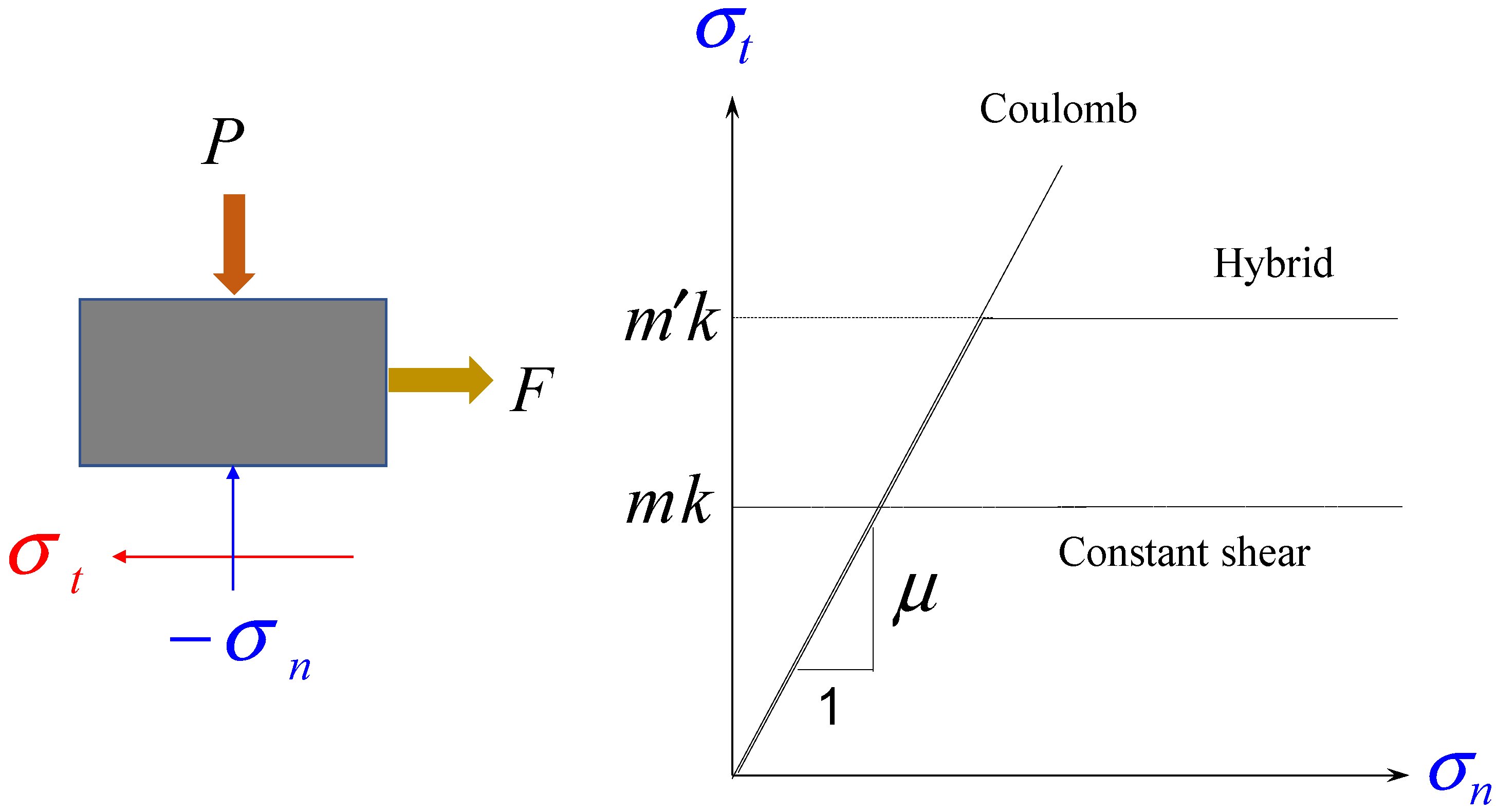
As shown in
Figure 1, the frictional stress
defined at the material–die contact surface is in a functional relationship with the normal stress
and acts in the illustrated direction to prevent relative motion between the two objects. For this functional relationship, the Coulomb and constant shear friction laws are widely used in metal forming mechanics [
19]. Hybrid friction is a combination of two friction laws, which follow the Coulomb friction law at low friction (with a constant friction coefficient
) and the constant shear friction law at high friction (with an increased friction factor
defined in
Figure 1).
Ring compression tests often come up when discussing the Coulomb friction law (with friction coefficient) or constant shear friction (with friction factor). Although ring compression tests help understand friction, they do not always provide a reasonable basis for evaluating it. The results of tracking the height of the ring specimen and the change in its inner diameter, that is, the experimental friction calibration curves, imply the friction characteristics. The friction calibration curves of the Coulomb and constant shear friction laws are similar, and equivalent values can be assumed to exist. Based on this fact, many researchers believe that the two friction laws are equivalent. However, this is generally not true. The change in normal stress at the contact surface in the ring compression test is relatively small compared to that in the forging. Therefore, even if the Coulomb friction law is used, the frictional stress does not significantly differ depending on the location. Thus, the two friction calibration curves should be similar to each other. Contrarily, the friction state of the contact surface during forging can be significantly different from time to time and from position to position [
40]. The Coulomb friction law or its variant is thus better than the constant shear friction law. Notably, the functional relationship between frictional and normal stresses is significant, especially when studying wear.
Assuming that there is a linear relationship between the normal and frictional stresses at the contact surface, the Coulomb friction law is expressed by the following equation:
where the function
reflects the effect of the relative velocity
on frictional stress
, and the following function is widely used:
where
a is a positive constant that is small compared to
.
In the sticking contact surface belonging to the plastic region, the shear stress must satisfy not only the equation of equilibrium, but also the yield criterion. On the other hand, the frictional stress acting on the contact surface where slipping occurs in the plastic region must satisfy not only the equation of equilibrium and yield criterion, but also the friction law. Since the Coulomb friction law in Equation (1) also deals with sticking conditions, there is no mathematical problem in expressing all types of contact stresses, including the frictional stress in the sliding contact surface and the tangential stress in a sticking region. As a result, Equation (2) effectively keeps the frictional stress from being greater than
k when the Coulomb friction law is used. If
exceeds
k, then
should be small enough to meet the yield criterion. Thus, sticking should occur in the extreme case that
is sufficiently large. What should be noted here is that the tangential stress in a sticking condition generally does not reach the yield stress in pure shear (
k) [
19].
The traditional Coulomb friction law, which considers the friction coefficient as a constant, also poses some problems in metal forming. First, there is a fundamental problem regarding the simple linearity of normal and frictional stresses. Second, the lubrication regime changes at the contact surface due to the extreme tribological states during metal forming being inevitable. Therefore, the friction coefficient is bound to change during metal forming.
Wilson and Cazeault’s work [
48] found that the friction coefficient during a wax-lubricated strip drawing was almost zero in the thick film lubrication regime. In contrast, it increased to around 0.16 in the boundary lubrication regime. The friction coefficient varied drastically with the die angle in the strip drawing, especially around the die semi-angle ranging from 15 °C to 20 °C, implying that the lubrication regime change caused a drastic change in the tribological condition of friction and die wear. This fact emphasizes that the friction coefficient is the function of not only a material, die, and lubricant property, but also the process geometry and sliding speed [
40]. Notably, the latter governs the mechanical and tribological state of the lubricant, which is concerned with the lubrication regime change.
To solve the problem of the traditional Coulomb friction law described above, Lee et al. [
33] formulated the friction coefficient in Equation (1) as a function of state variables such as pressure, surface strain of the material, and temperature. To improve practicality, a separable variable function consisting of the influence of each state variable, that is, the weight, was used, as shown in the following equation:
where
is a friction constant and
,
, and
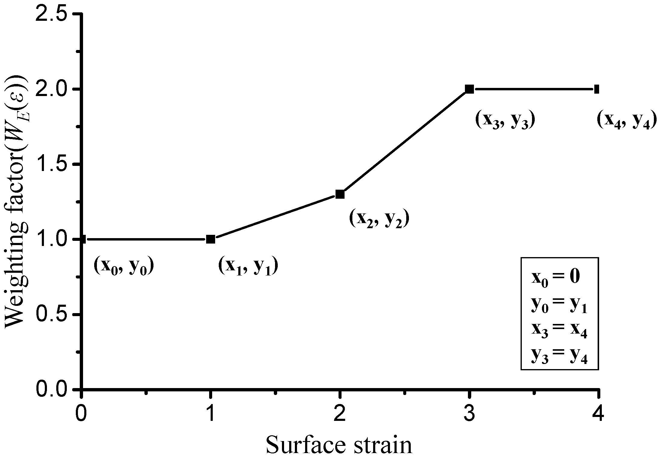
are weighting functions of surface strain, temperature, and pressure, respectively. Each weighting function was defined as a piecewise linear function. For example,
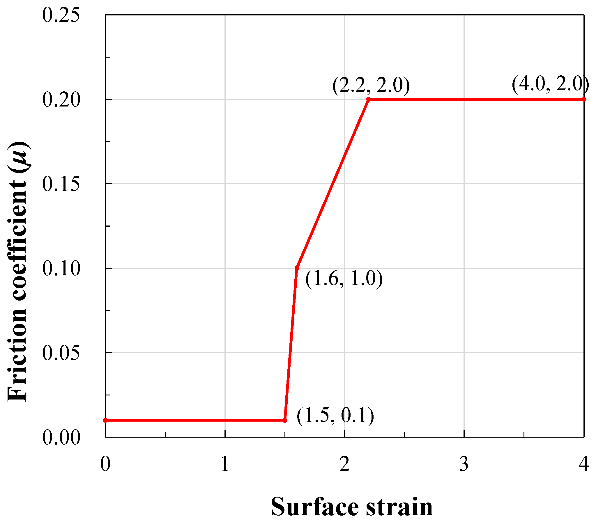
Figure 2 shows a piecewise linear function of
.
3. Evidence of LRC and Its Effect on the Processes and Products
3.1. Case 1: Cold Forward Extrusion of Pure Aluminum Using Step Die
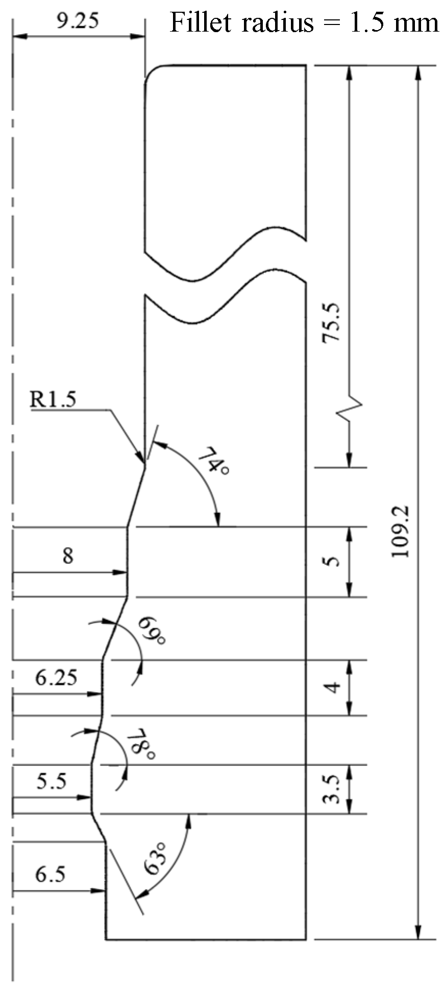
The multi-step forward cold extrusion with poor-lubricated surface, defined in
Figure 3, is a typical example where a friction coefficient linked to the state of the contact surface must be used. When a constant friction coefficient over a value is used for the multi-step cold forward extrusion process with a moderate reduction of area, plastic deformation near the skin at the inlet container may occur when the lubricant film on the surface is thin. Joun et al. [
19] solved this problem by using a varying friction coefficient. The previous method of imposing the friction coefficient on the specific area or region is impractical.
The friction force inevitably generated from the exit side increases the material’s hydrostatic pressure, leading to the increase in contact pressure at the material–die interface inside the container. Notably, it causes a vicious cycle of increased friction and extreme plastic deformation in the case of a significant friction coefficient. This phenomenon differs from plastic deformation in the inlet container, even though the friction at the exit is so substantial that burnt skin can be observed in the actual process. However, this phenomenon has nothing to do with the fundamental problem of the Coulomb friction law. To visualize this phenomenon, a simulation was conducted for the multi-step cold forward extrusion process using the elastoplastic finite element method. The analysis information is as follows:
- -
Flow stress of the material: MPa;
- -
Young’s modulus of the material: 90,000; Poisson’s ratio: 0.3;
- -
Rigid dies;
- -
Ram’s speed: 1 mm/s;
- -
Frictions:
Case (1) Constant friction coefficient ;
Case (2) Surface strain-dependent friction coefficient defined by the piecewise linear function of the following vertices:
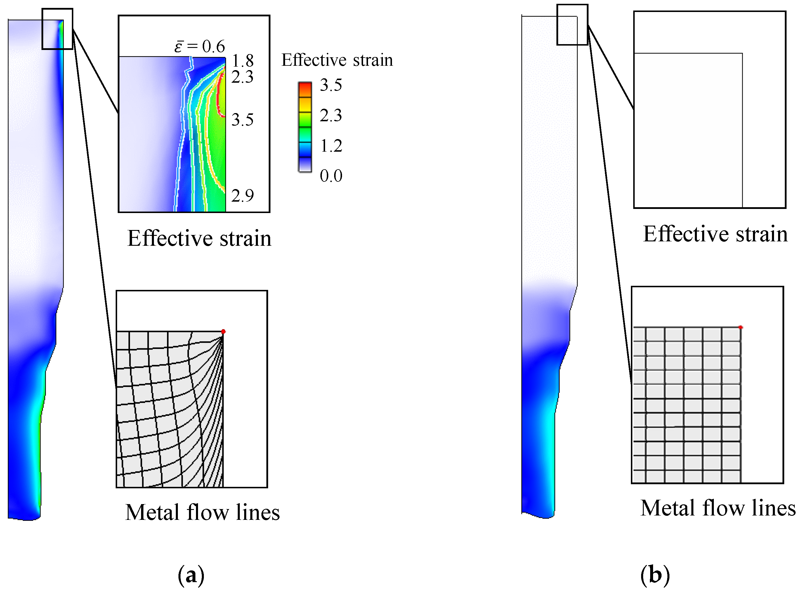
The initial finite element mesh system with 5500 uniform quadrilaterals (each quadrilateral size: 0.24 (x-direction) × 0.43 (y-direction) mm) was employed. The remeshing function was turned off to accurately monitor the skin-shearing occurring in Case (1) directly from the FE mesh system. The upper material’s effective strain and grid distortion at the final stroke are shown in
Figure 4. The maximum strain reached 1.8, implying that the friction coefficient increased to over 0.18 in the third step near the exit. It was found that the upper material in Case (1) started to be plastically deformed when the leading edge of the material touched the third step, causing the skin-shearing of the upper material. On the contrary, the upper material in Case (2) maintained rigid-body translation throughout the process even though the maximum friction coefficient exceeded 0.18 in the third step.
It is empirically known that the lubricated film coated on the material does not suffer much damage within the container during the cold forward extrusion process. Experiments suggest that the material’s surface at the third step should be severely damaged and scratched even though the upper material inside the container experiences no distinct plastic deformation. Because the contact surface with the undamaged lubricated film maintains low friction, the frictional stress does not cause a high enough pressure to cause plastic deformation at the inlet container. On the other hand, damage to the lubricated film on the exit side can be crucial due to a considerable frictional stress and excessive heat. This tribological phenomenon implies that the LRC occurs with a moderate area reduction during the multi-step cold forward extrusion. Therefore, the friction coefficient at the exit should be significant while that at the entry should be low, and the varying friction coefficient with the contact surface state is thus essential.
By simply expressing the damage to the lubricant as a function of surface strain, the method used in Case (2) solved the excessive friction problem of the Coulomb friction law. This tribological phenomenon can occur in the actual processes even though the material in the inlet side remains in the dead metal zone during the entire extrusion. This case emphasizes that the magnitude of the friction coefficient must change as the state of the contact surface changes to reflect the phenomenon of LRC. It is this example that demonstrates the LRC phenomenon step by step and highlights the importance of the friction model.
This example is very useful in explaining LRC because the effective strain occurring at all contact surfaces is directly related to the deterioration of the lubricant. In actual forging, significant strain may occur on the surface without contact with the die. In this case, it may be unrealistic to treat the friction coefficient as a function of the surface strain itself because the strain does not accelerate the deterioration of the lubricant. Quantification of the degree of lubricant degradation at the contact surface is thus important.
3.2. Case 2: Critical Surface Strain in Hot Forging of Aluminum Alloy Piston
Lee et al. [
33] conducted a non-isothermal FE analysis of a hot forging process of an A4032 alloy piston. The surface of the material was well-lubricated by a solid graphite film. The flow function obtained from compression tests was evaluated in the previous study, revealing that the maximum error of this flow function was 1.43%. It is accurate enough for us to focus on friction.
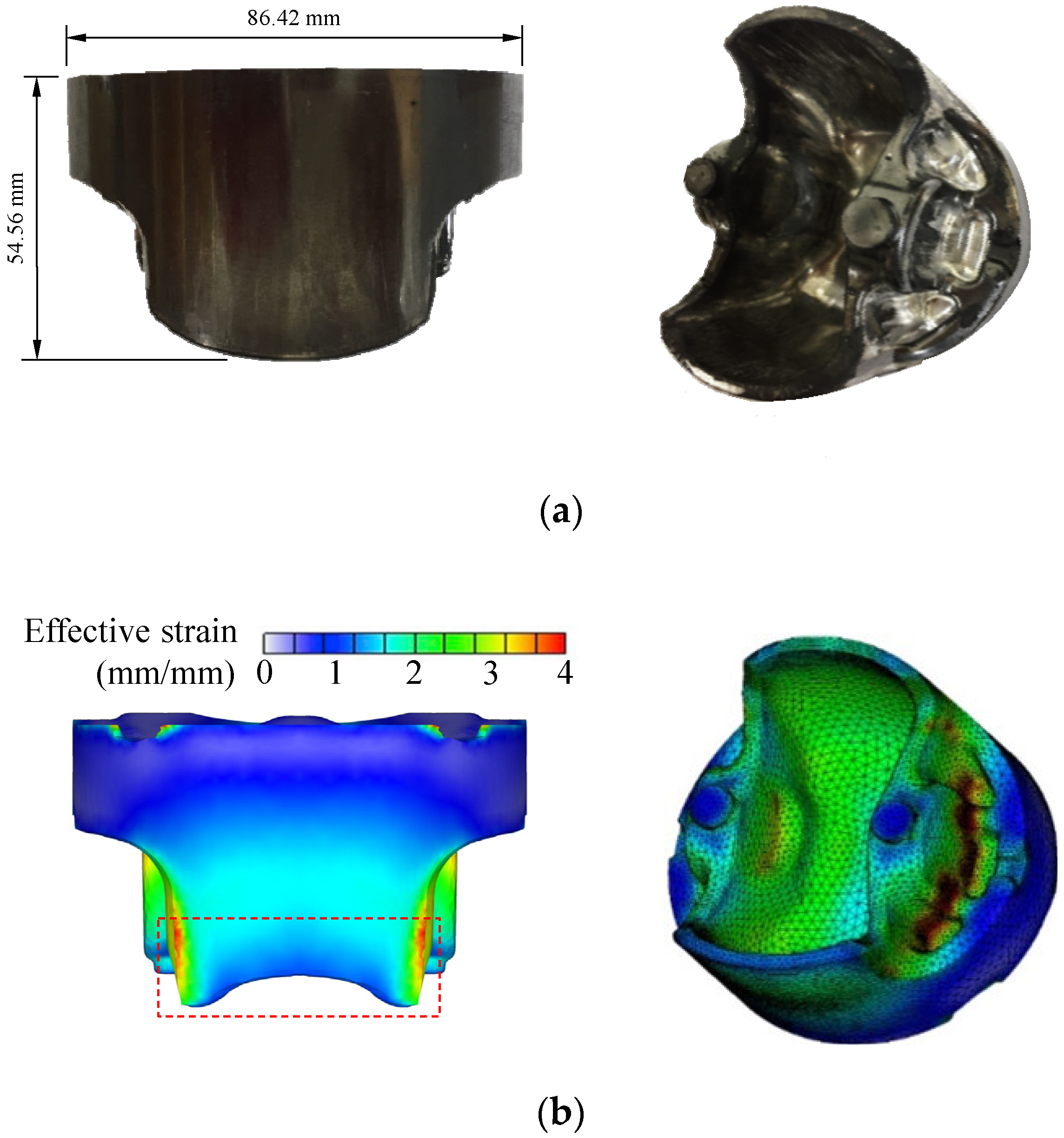
Figure 5 compares the experiments and FE predictions of aluminum piston hot forging for an assumed constant friction coefficient of 0.2. As shown in
Figure 5a, the experiments of aluminum piston hot forging showed that the bottom of the material was deformed to be convex. Still, the rigid-thermoviscoplastic FEM predicted a concave shape, as shown in
Figure 5b. Lee et al. conducted FE analyses of the process using various commercial software and various traditional friction laws with various constant friction coefficients [
33] and friction factors [
49]. It was concluded that the FE predictions obtained by the continuous friction conditions cannot express the actual situation.
As can be seen in
Figure 5a, the lubricant in the regions with large effective strains was significantly damaged. In contrast, the lubricant film on the lateral side does not appear significantly damaged, implying that the LRC from a thick film to boundary lubrication schemes occurred in the regions where the material surface’s color became bright. The friction coefficient should thus change from position to position depending on the damage of the lubricant. A scientific approach to damage to the lubricant film is needed. The friction coefficient can thus be thought of as a function of state variables such as pressure at the contact surface, temperature [
47], strain and strain rate, and relative speed of material to die.
However, this was assumed to be dependent on the strain of the material at the surface, which is called surface strain, since the surface strain of the material may represent the degree of damage to the lubricant. The effective strain of the material at each location is different, as can be seen in
Figure 5b, where the pattern of effective strain distribution resembles the color of the scratched surface. Considering this, Lee et al. set the friction coefficient at 0.1
.
Lee et al. used an optimization function of HyperStudy [
50] to find the optimized weighting function
in terms of deformed shape along with the initial guess shown in
Figure 2. The results of the optimized friction coefficient function,
, are shown in
Figure 6. These results highlight that the friction coefficient changes rapidly when the surface strain reaches around 1.5, called critical surface strain [
33]. This implies that the changed color of the material’s surface represents the degree of lubricant damage and the evidence of the LRC.
With the variable friction coefficient expressed as this weighting function, a deformed shape similar to the experiment was predicted, as shown in
Figure 7. This example is sufficient to dramatically demonstrate the LRC represented by the deterioration of lubricants and its effects on friction during hot forging. This can occur in the forging of materials with a low strain hardening capability when the material flows through narrow die gaps.
It should be emphasized that the FE predictions obtained with the optimized friction condition show a smoother strain distribution than those of the constant friction, as shown in
Figure 7. This phenomenon may mean that the lubricant itself has the tendency to spread deterioration to its neighbors to the extent possible.
3.3. Case 3: Sudden LRC in the Automatic Multistage Cold Forging of Aluminum Alloy Yoke
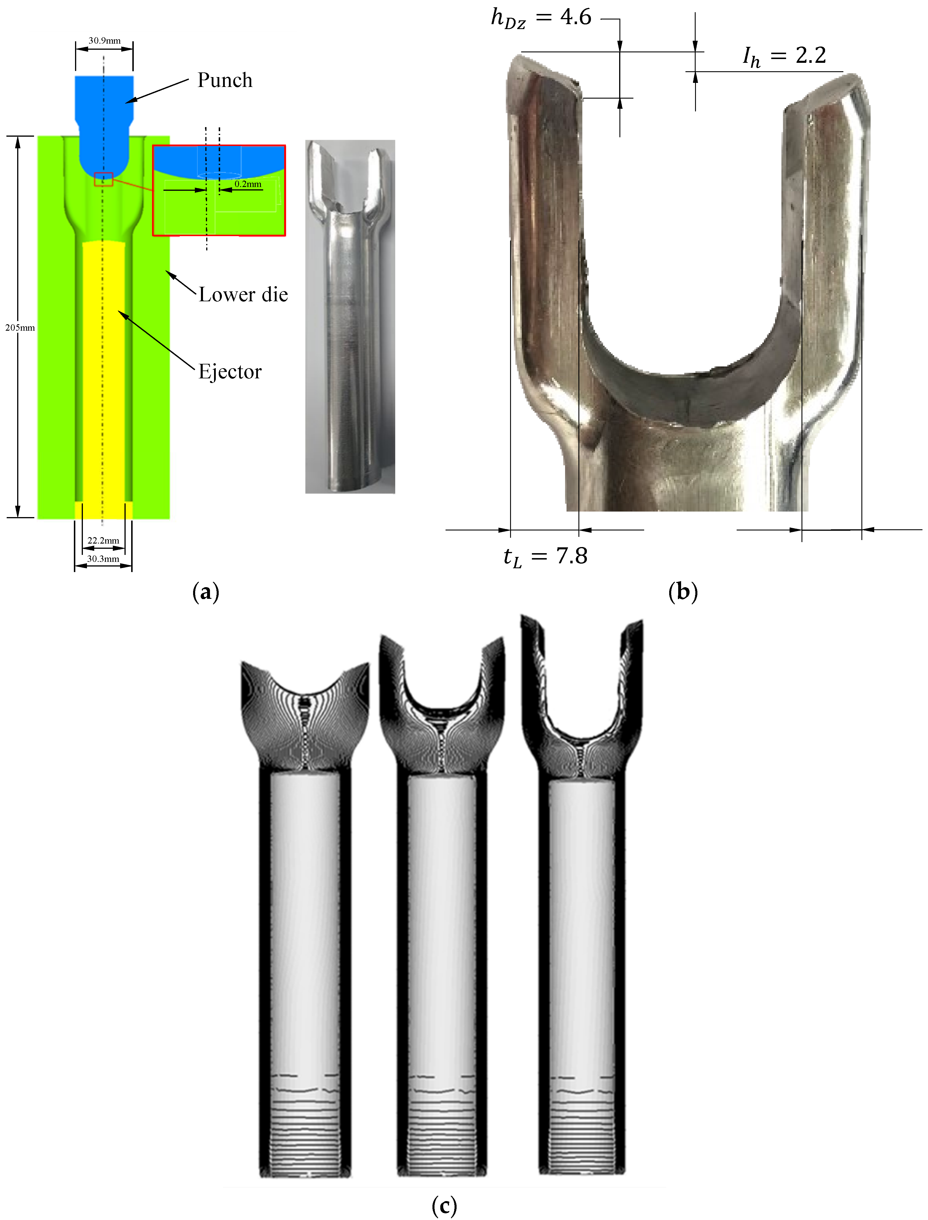
Figure 8 describes a part of the AMSCF [
46] of an aluminum (Al6082-T6) steering yoke for passenger cars and its fifth stage’s design. As shown in
Figure 8a, the punch was offset approximately 0.2 mm from the center of the process. As a result, as shown in
Figure 8b, it created an ear height difference of 2.2 mm. A hundred test specimens, which were sawn from an aluminum alloy rod, fabricated for forging but uncoated, were forged by the AMSCF machine in a forming oil environment. All the test forgings exhibited almost the same macroscopic configuration except the first 30 trials. Because the metal forming occurred in the very complex working conditions of the AMSCF, no information about friction could be scientifically obtained using conventional methods. Hamid et al. [
46] numerically found the frictional conditions that caused this difference in the ear height.
Hamid et al. [
46] characterized the material’s flow behavior, and its validity was evaluated by comparing the FE predictions of the compression tests with their experiments in terms of the compression force–stroke curve. It was confirmed that the average error was within 1.9%, implying that the friction can be decoupled from the process-dominant flow behaviors of the material. However, using various constant friction conditions (
), they could not obtain the results that satisfied the experimentally measured difference in the ear height of 2.2 mm, as shown in
Figure 8b. With a constant coefficient of friction, the maximum predictable ear height difference was 0.6 mm, which is very small compared to the experimental value. Notably, other than LRC, there is no way to explain this result.
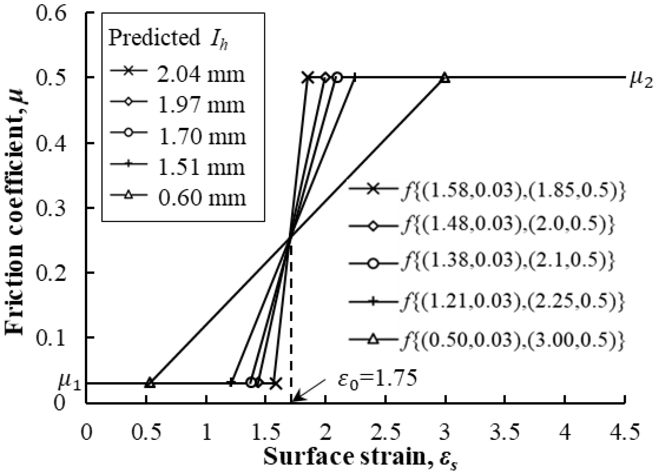
Meanwhile, Hamid et al. assumed the friction coefficient to be a function of the surface strain of the material at the contact surface, as shown in
Figure 9. They conducted FE analyses for various friction coefficient functions using the rigid-thermoviscoplastic FEM. The number of tetrahedrons ranged from 99,000 to 101,000 and around 320 remeshings were conducted. As shown in
Figure 9, a difference in ear height similar to the experimental result was predicted only in the case that a jump in the friction coefficient occurred at the critical surface strain of 1.75. Interestingly, the larger the slope of the function, the closer the predicted result was to the experimental value. It was confirmed that the optimal value of the critical surface strain was 1.75, at which the LRC [
40] occurred.
Hamid et al. explained this as a tribological shifting phenomenon. As the temperature rose, the viscosity of the forming oil for the AMSCF decreased. As the voids in the contact surface decreased due to high pressure and severe shear deformation, the lubricating forming oil suddenly lost its function or escaped from the contact surface. It caused the fluid lubrication-induced LRC, resulting in a rapid increase in friction. The ear height difference, owing mainly to the extraordinary lubrication phenomenon of tribological LRC, was believed to appear when the strain hardening of the material was slight. The temperature softening is extreme, and it occurs when the temperature, surface strain, and pressure conditions at the contact surface reach critical values. It is concluded that the tribological shifting phenomenon was owing to a drastic LRC, the reasons of which are mechanically and tribologically mixed by the deformation and temperature of the material and lubricant.
This example is also sufficient to highlight the dependence of friction on state variables, which can be explained as the effect of the LRC on friction even though the tribology in the AMSCF process is extremely complicated.
In this process, the final shape is determined by very complex macroscopic phenomena [
46]. What is observed from the analysis results is that the greater the jump in friction coefficient at a specific strain, the closer the predicted results are to the experimental value. In addition, at the same time as LRC, all state variables such as hydrostatic pressure, effective stress, and effective strain rate and the increase rate of forming load change rapidly. Considering the influence of the friction coefficient especially at the critical surface strain, it can be argued that the LRC leads this change in macroscopic responses.
3.4. Case 4 Skin-Shearing Phenomenon in the Round-to-Half-Circle Drawing Process of SUS 304
Heo et al. [
47] studied the skin-shearing phenomenon shown in
Figure 10 that occurred during the round-to-half circle drawing process of SUS 304. The shape drawing process uses the grease containing the additives as a lubricant, and thus, considerable friction cannot occur at room temperature because its normal stress at the contact surface is smaller than that in the cold forward forging of
Section 3.1, for example. However, the lubricating effect of the grease may rapidly be lost as the temperature of the contact surface rises due to friction heat.
This problem is a chronic feature of the drawing process in which the relative motion between the material and the die is extreme. When high pressure is applied in a specific part of the die, excessive generation of friction heat centered on this part can dominate the process and product quality of the drawing process. Therefore, temperature is important in terms of friction. Of course, an increase in temperature destroys the lubrication, which causes a change from the thick or thin film lubrication regime to the boundary lubrication regime and promotes die wear due to high heat and relative material–die movement, leading to increased friction. In any case, temperature is an important factor that affects friction and wear in drawing and can represent a state variable related to the lubrication phenomenon.
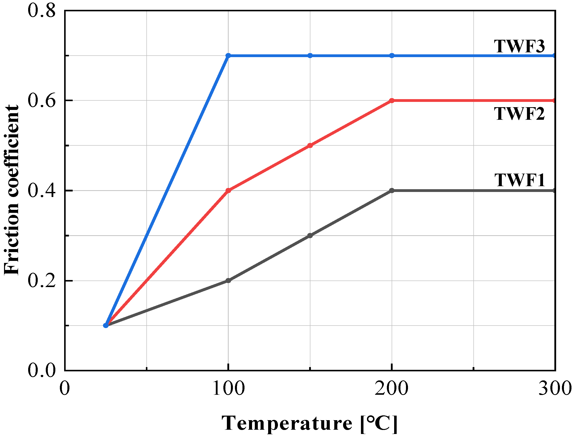
In the numerical study of Heo et al., a temperature-dependent friction coefficient was thus used, as shown in
Figure 11. However, the hybrid friction model was used, following the Coulomb friction law. Still, the maximum shear stress was regulated not to exceed 95% of the pure shear yield stress. The flow stress of the material used is the result of previous research [
51], and the maximum error was 7.7% in the range of test temperature and strain rate. It is of sufficient accuracy for macroscopic research purposes.
Heo et al. used the combined steady-state flow and unsteady-state temperature method to reveal the local heating generated by friction in the drawing process, that is, the friction heat ball phenomenon [
47]. Due to this friction heat ball, a part of the die is heated in a vicious cycle of heat generation and increased friction. Eventually, the friction heat ball heats the material locally, resulting in a LRC and rapid temperature softening of the surface. It ultimately led to the phenomenon of skin-shearing during drawing. Note that before the skin-shearing phenomenon, the LRC continuously occurred during the shape drawing because of the vicious cycle, which brought out the steady increase in die temperature.
Heo et al. conducted FE analyses under various frictional conditions, including TWF1, TWF2, and TWF3, defined in
Figure 10. Special mesh systems which were extremely refined in the contact interface were employed. The superfine tetrahedrons with edge lengths less than 0.02 mm were purposely generated near the burr-like defect and skin-shearing region.
Figure 11 compares the experiments and the FE predictions of TWF3, showing an excellent qualitative agreement with each other. As shown in
Figure 11, the TWF3 predicted the skin-shearing phenomenon, which is quite peculiar. The possibility of this phenomenon occurring was discovered in the FE predictions of TWF2, but TWF1 did not even predict the possibility of skin-shearing occurring. It means that high friction causes scratches and the wear of the die as the lubricant does not play its role due to the high temperature in the friction heat ball area, resulting in the deterioration of the boundary lubrication regime and an extreme increase in the coefficient of friction. The validity of the high friction coefficient was confirmed because the lubricant experimentally flowed like water at the outlet, and smoke was generated due to frictional heat.
Heo et al. showed that the size of the FE-predicted defect tended to increase as the tetrahedral element edge length at the edge and plate area where the defect was created became smaller. In other words, it was confirmed that the FE predictions converged with the experiments.
Although this case concerns a shape drawing process, which is an extreme metal forming process in terms of friction, it is sufficient to highlight the influence of LRCs that occur over time due to the temperature dependence of friction during drawing.
Skin-shearing that occurs during drawing is a very unusual phenomenon. Various attempts were made to predict this phenomenon but failed [
47]. Not only does the loss of lubricant function due to heat energy accumulated in the die cause an extreme increase in friction, but the increased surface temperature of the die locally heats the surface of the material, causing a decrease in flow stress at the material’s surface and finally increasing the skin-shearing of the material. Without the LRC by the drastically decayed function of the lubricant, it is impossible to explain the skin-shearing phenomenon.
4. Conclusions
The importance of friction during bulk metal forming was emphasized since the material and process during bulk metal forming experience extreme competition between flow and friction. It was revealed that the lubrication regime change is inevitable during bulk metal forming accompanying moderate plastic deformation. Multi-step forward extrusion and drawing processes are vulnerable to the lubrication regime change (LRC) owing to large sliding motion at the material–die interface. Aluminum forging is also vulnerable to the LRC because the aluminum alloys belong to low strain hardening materials, which may easily experience the exaggerated effect of the lubrication regime change. Strictly speaking, most forging processes accompany any LRC owing to the effect of material flow and heat transfer. This study showed the cases of typical LRC in the bulk metal forming processes, including the multi-step forward extrusion process, round-to-half circle drawing process, and cold and hot forging processes of aluminum alloys. A few new findings are summarized as follows:
- (1)
It was emphasized that a multi-step cold forward extrusion process with a moderate reduction of area is a typical example exposed to the problem related to the LRC since large sliding motion, high hydrostatic pressure, and large deformation of material at the exit exaggerate the continuous evolution of the LRC from the thick film to boundary lubrication regimes via thin film and mixed lubrication regimes;
- (2)
The flow characteristics of aluminum alloys for bulk metal forming purposes are expressed by low strain hardening, high temperature softening between 200 °C and 300 °C, and the narrow transition region between cold and hot forging. In this forming environment, friction can dominate the macroscopic plastic deformation during bulk metal forming, and LRC can thus easily occur, leading to macroscopic instability;
- (3)
When the lubrication regime changes, the friction coefficient greatly depends on the state of the contact surface and the state variables at the contact surface (strain rate, strain rate, pressure, temperature, relative speed of material to die, etc.). From a process analysis perspective, the major factors that govern the state of lubrication include the material’s surface strain (a measure of the damage to the lubricant) and temperature, which are major factors affecting the LRC;
- (4)
An increase in surface strain promotes direct contact between the material and the die, which leads to the creation of debris and the acceleration of friction and wear. For this reason, when the strain at the contact surface reached the critical surface strain in the hot forging of an aluminum alloy material coated with a lubricant, the friction coefficient rapidly increased. A similar phenomenon occurred in the AMSCF of aluminum alloy operated in a forming oil environment, which resulted in a sudden change in the lubrication state at the specific surface strain during metal forming because of a drastic LRC.
In summary, as Wilson crucially criticized four and a half decades ago, the traditional Coulomb friction law, which assumes a constant value of friction coefficient, is not appropriate in most bulk metal forming where the state of the contact surface (pressure, lubrication state of the material surface) changes rapidly. Experiences say that most forging processes accompany a LRC during the process. However, most researchers rely on the traditional friction law based on a constant friction coefficient. In the case of lightweight materials, including aluminum and magnesium alloys, friction can have a significant impact on the process. Careful attention is thus required to solve sophisticated tribological problems in bulk metal forming.
Finally, it is recommended that a quantity to measure the damage of lubricant be developed to accelerate the study of friction in bulk metal forming.
