1. Introduction
Machine vision and machine learning are known as promising technologies in tribology [
1,
2]. Particularly, advancements in machine vision for surface roughness characterization are attributed to improvements in computational power and in digital image sensing performance. Blasted surfaces prior to the deposition of lubricants are required to maintain precisely controlled roughness. Although conventional methods (e.g., visual or tactile comparison with a sample comparator) enable the roughness measurement of a blasted surface, there exist industrial demands for faster and more accurate measurement.
In order to satisfy these demands, various machine vision techniques have been developed for measuring surface roughness [
3,
4,
5,
6]. One approach involves analyzing light intensity on a grayscale level, which has been correlated with surface roughness [
3]. Additionally, wavelet transform has been employed to examine surface images after grinding and milling, using frequency normalization to enhance precision [
4]. Another method, subpixel edge detection, was introduced for the in-process measurement of surface roughness, providing accurate surface contours for roughness prediction [
5]. Another reported machine vision approach is to characterize surface texture for evaluating the arithmetic average surface roughness of a grinded workpiece [
6]. This approach uses grayscale co-occurrence matrix features for surface texture characterization. Correlation between surface roughness and the matrix feature-based principal component is modeled by using a multiple regression analysis.
Along with these developments in machine vision, machine learning models have been developed for the prediction of surface roughness and for the characterization of surface texture [
7,
8,
9]. Particularly, neural networks has been used for predicting surface roughness. One research work selected a convolutional neural network (CNN) for image-based roughness measurement [
7]. The micro-scale images of a surface produced by die-sinking EDM were selected as training dataset for CNN. Other research has focused on a vision-based artificial neural network (ANN) for predicting surface roughness [
8,
9]. Surface images obtained at various milling parameters were selected for the training dataset in ANN [
8]; the parameters included speed, feed rate, and the depth of cut. After the training and testing processes, the arithmetic average surface roughness was determined by the ANN model. A computer vision-based ANN method was developed for the surface roughness prediction of a turned workpiece [
9]. The ANN model was built from datasets obtained with various process parameters (speed, depth of cut, feed rate, and grayscale). The arithmetic average surface roughness from the model was compared with those measured with a stylus-type profilometer. In order to increase the accuracy of these machine learning models, it is necessary to obtain as large of a training dataset as possible.
Despite these recent advancements in machine vision and machine learning, little has been found related to a machine vision system for the roughness measurement of blasted surfaces. In order to use a machine vision system for the quality inspection of a manufacturing process, the system needs to maintain fast execution and high accuracy.
In this article, a simple machine vision algorithm is proposed for predicting the arithmetic average roughness of shot- and sand-blasted surfaces. The proposed machine vision system using a digital microscope allows the capture of micro-images, analyzing captured images with Otsu’s method and a proposed image filter, and predicting the arithmetic average roughness of blasted surfaces.
2. Materials and Methods
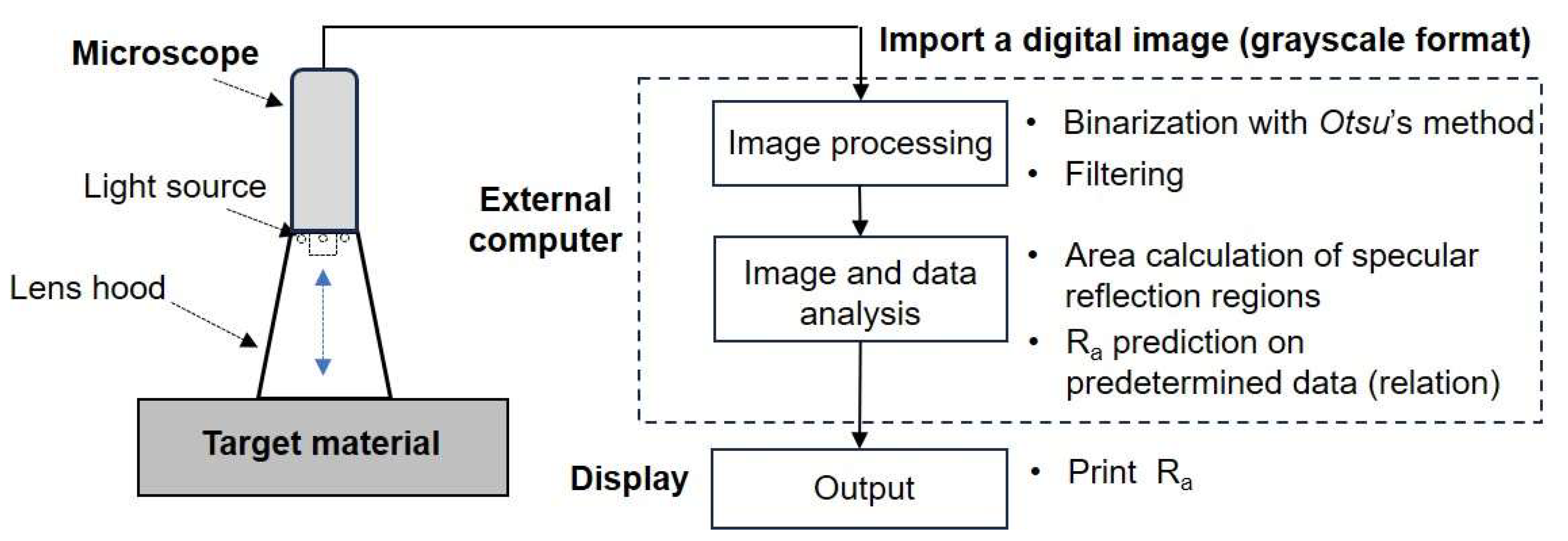
The proposed machine vision system includes a digital microscope with a lens hood, an external computer, and a display, as shown in
Figure 1. A conical-shaped lens hood was installed to block out external lights that can affect a target surface. Micro-images captured with the microscope (charge-coupled device sensor with a resolution of 1.3 M pixels (1280 × 960), ring illumination method, 1200×) were transferred to an external computer for image processing (binarization of the submitted grayscale image and filtering). After the image processing, image and data analysis were employed on the computer: the area calculation of the selected specular reflection of light on a filtered image, and the prediction of the arithmetic average roughness (R
a) on predetermined data (e.g., data obtained with a surface roughness comparison sample). Finally, the predicted roughness was displayed.
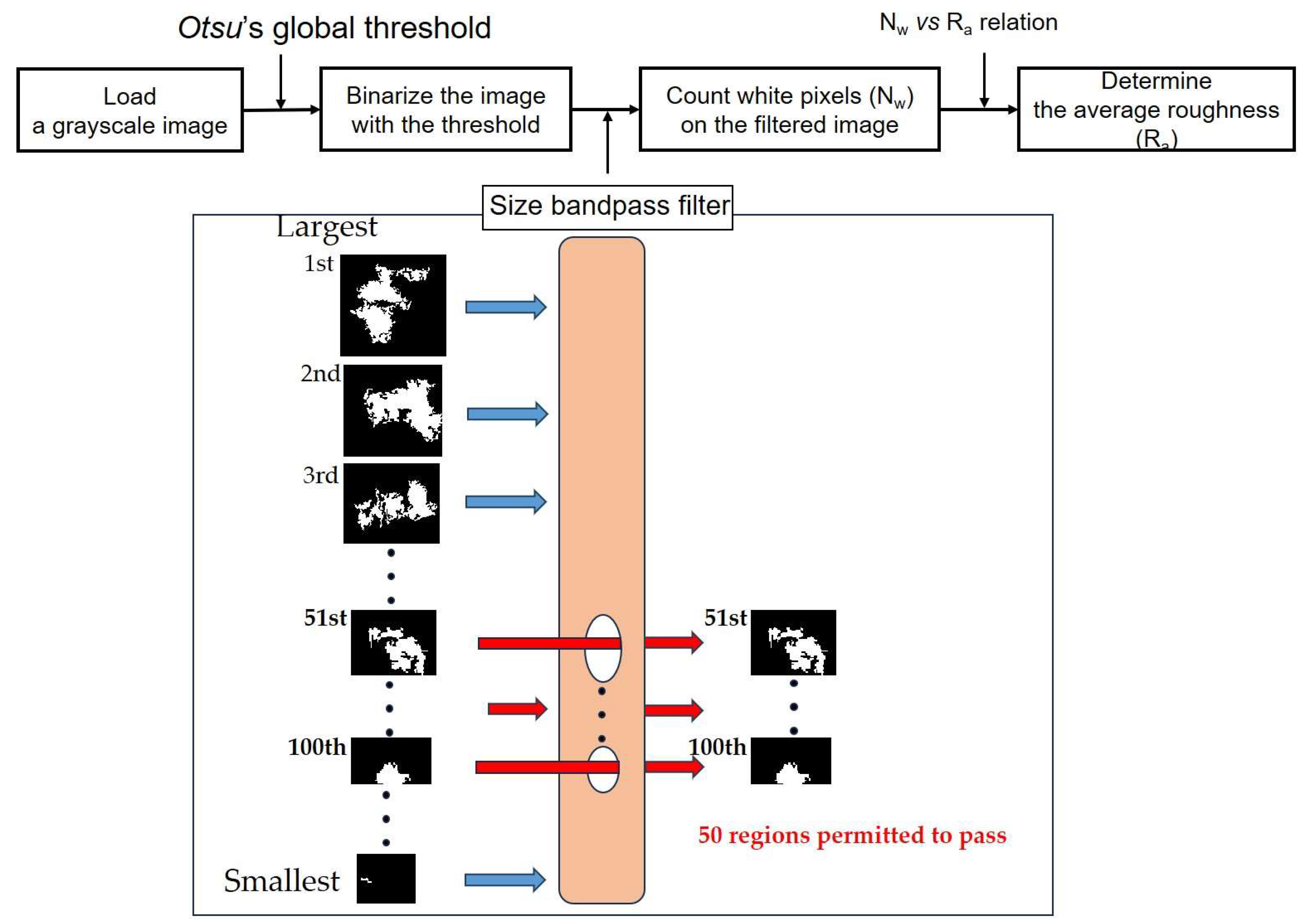
A detailed procedure for determination of the arithmetic average roughness is described in
Figure 2. In this machine vision algorithm, it is necessary to import a grayscale image. The imported grayscale image is binarized. In this algorithm, Otsu’s method, a classic thresholding approach in image segmentation, was chosen because of its simplicity and speed [
10,
11]. The method is also known to be better than the original one in segmenting images corrupted by noise [
12,
13]. On a generated binary image, the specular reflection of light is presented as white regions. A single binary image contains various sizes and shapes of white regions (that is, a region is the group of white pixels).
In this study, a specific number of regions were chosen with a size bandpass filter. The filter played the following roles. All regions were arranged in order from the largest. Among them, 50 regions (from the 51st- to 100th-largest ones) were allowed to pass through the filter. Here, ‘50’ is the specific number of regions; the specific number, ‘50’, allowed us to minimize image noise and to obtain the adequate correlation between the percentage of white pixels and the arithmetic average roughness.
On the filtered binary image, the number of white pixels was counted and the average size of 50 regions was calculated. Note that the white pixels correspond to the specular reflection of light. For the purpose of establishing the correlation between the number of white pixels and the arithmetic average roughness, this study used roughness comparison specimens, with blasted surfaces that were well controlled. Based on the relation between the size of the selected regions and the arithmetic average roughness, the arithmetic average surface roughness after a blasting process can be predicted. The proposed image-processing algorithm code is presented in
Appendix A.
In this study, two types of blasted surfaces were prepared with shot and sand abrasives (commercial surface roughness comparison samples (nickel alloys) with fabrication standards GB6060.5, ISO 2632-2-1985, supplier: MC, China). The arithmetic average roughness (Ra) values of shot-blasted surfaces were 3.2 μm, 6.3 μm, and 12.5 μm. For shot blasting, high-carbon cast steel (53–60 HRC) shots ranging from 0.5 mm to 2 mm in size were selected. The continuous impact of shots was applied to the target surface at an air pressure of 2−7 bars. Stand-off distance between 15 cm and 45 cm was set based on the shot size. The selected sand-blasted surfaces also maintained 3.2 μm, 6.3 μm, and 12.5 μm in the arithmetic average roughness. In sand blasting, silica (5 Mohs) particles ranging from 0.5 mm to 2 mm were propelled at an air pressure of 2−7 bars and at a stand-off distance of 15−45 cm.
For image processing and analysis, four micro-images (magnification level: 1200×) were obtained at random locations on a surface at each roughness level; the blasted plates were 20 cm × 25 cm in size. The surface of the plate was divided into four equal parts. Four images were captured in each quadrant.
3. Results
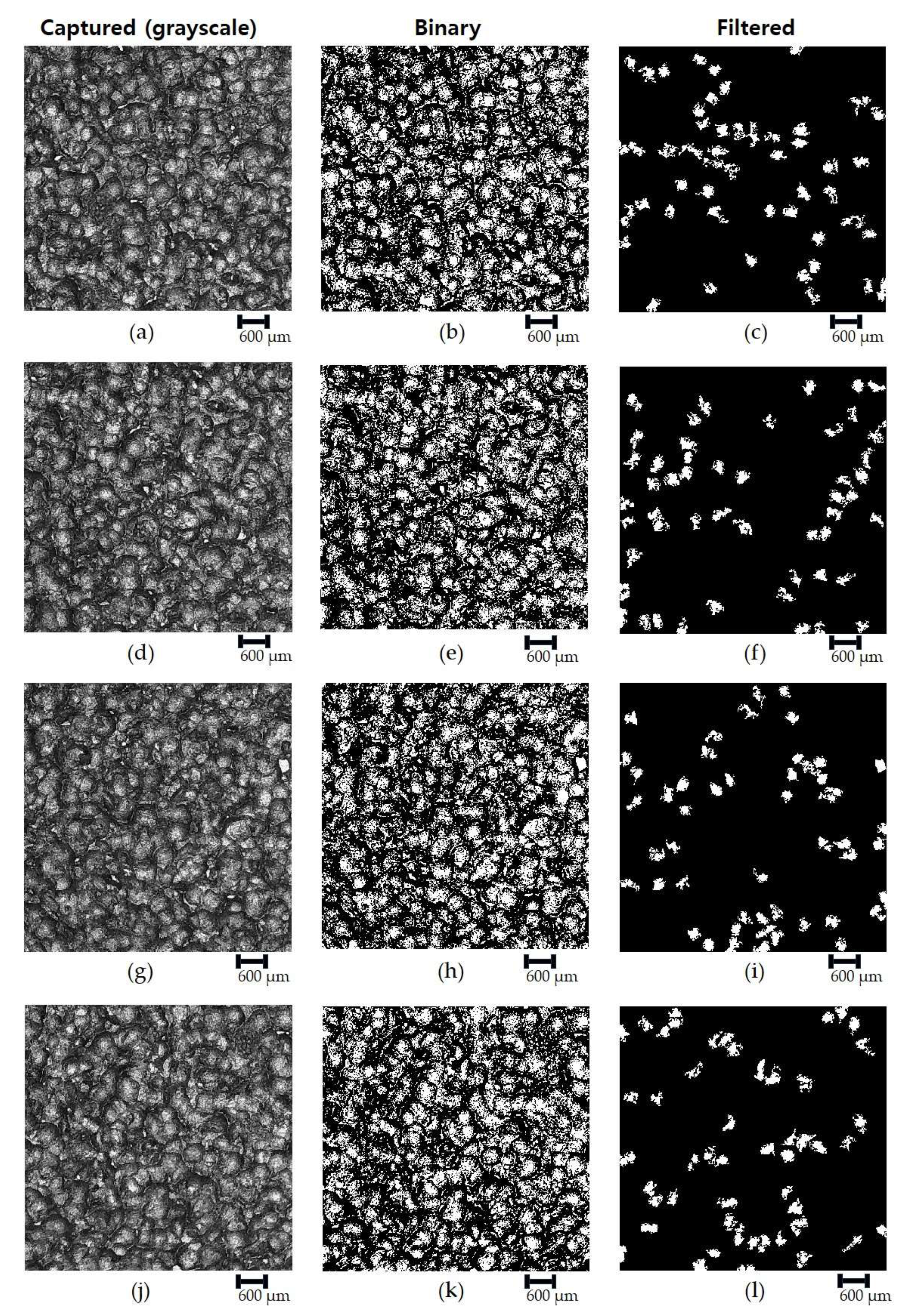
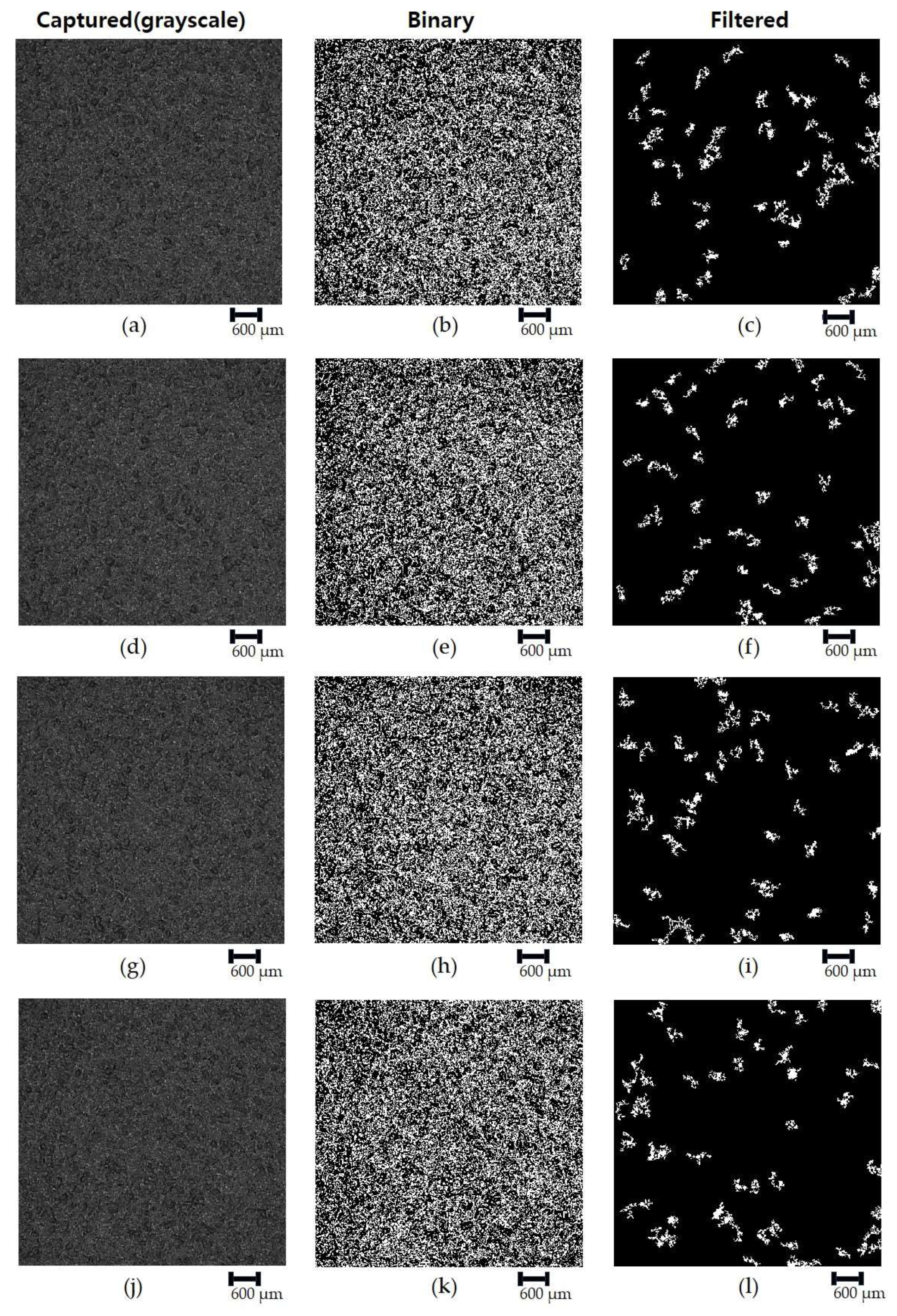
Figure 3 shows shot-blasted surface images with R
a of 12.5 μm.
Figure 3a,d,g,j presents grayscale images. Four images captured at random locations on the surface were selected (5 mm × 5 mm in size). Brightness and darkness on the grayscale image were determined with the specular reflection and diffuse reflection of light. The grayscale images were binarized with Otsu’s thresholding method, as shown in
Figure 3b,e,h,k. Otsu’s global thresholding method separates the submitted grayscale image into two classes, foreground and background. The foreground (white) corresponds to the regions of specular reflection, while the background (black) is associated with those of diffuse reflection.
Appendix B and
Appendix C present the histograms of grayscale images, representing the distribution of pixel intensities. The global thresholds for each image were automatically determined on the histogram, as shown in
Table 1. The thresholds were observed to vary with respect to the arithmetic average roughness of shot-blasted surfaces, while significant difference was not found among the four values at each roughness level. For sand blasting, the automatically determined thresholds were found to remain lower than those for shot blasting, ranging from 0.18 to 0.27. The values were close to each other without regard to the roughness level.
Figure 3c,f,i,l has the images to which a proposed size bandpass filter was applied. In the filtered images, fifty white regions were presented. The total number of white pixels was counted on each image and averaged, as shown in
Table 2.
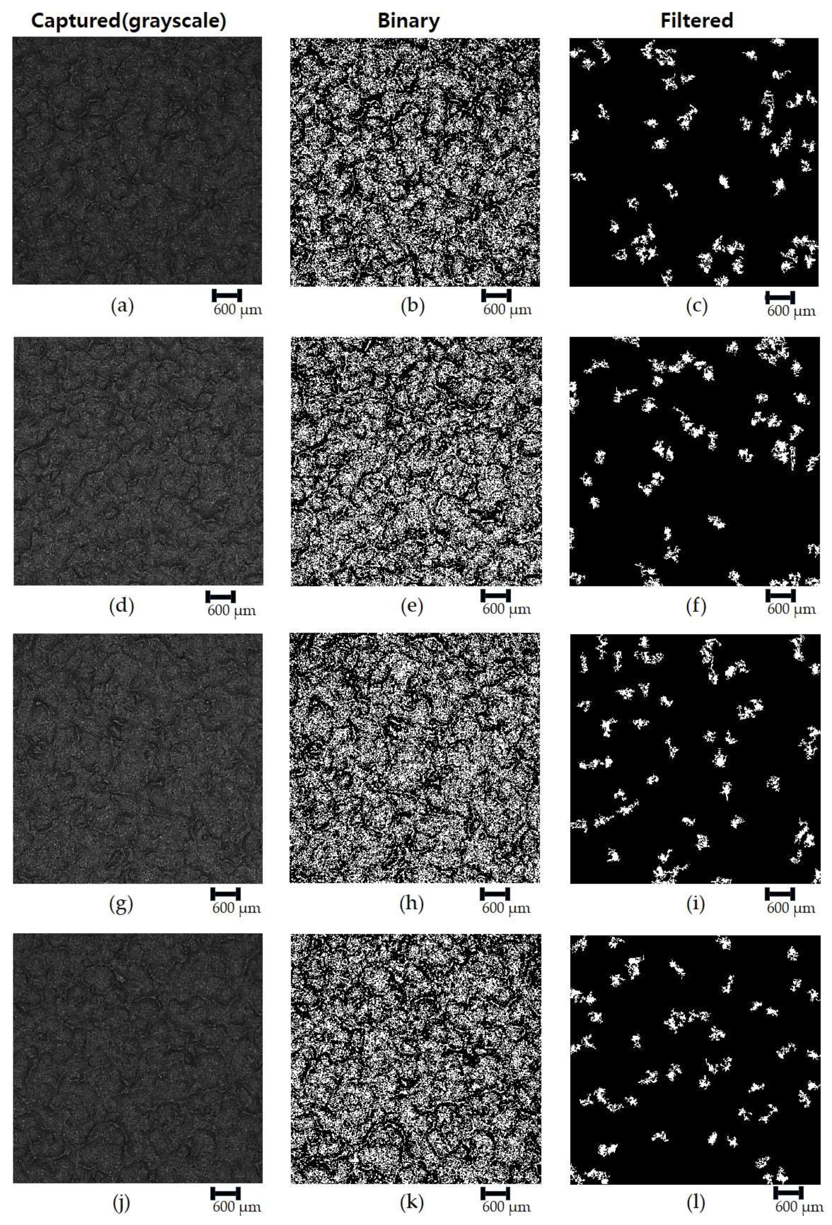
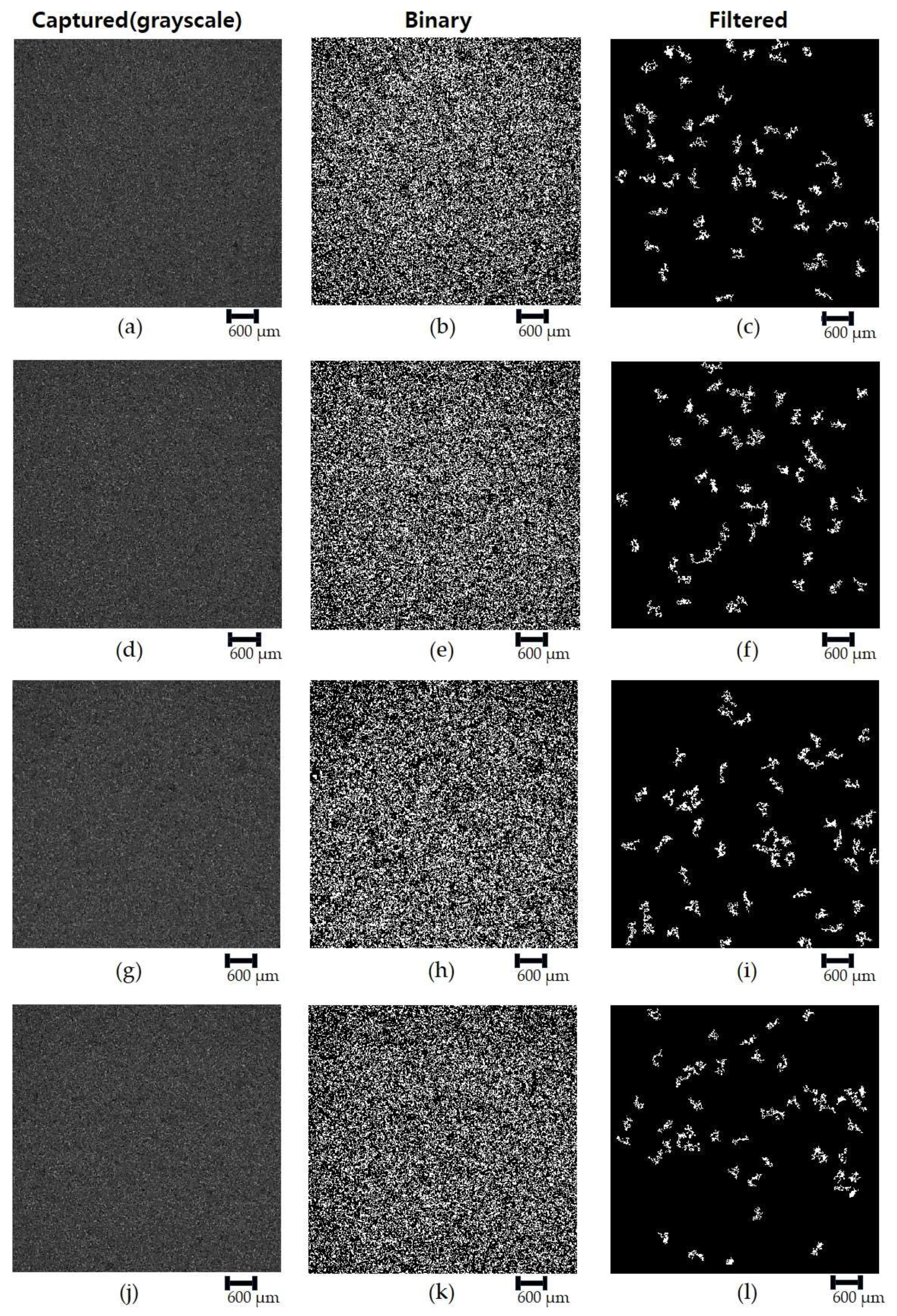
Figure 4 shows shot-blasted surface images with R
a of 6.3 μm.
Figure 4a,d,g,j presents captured grayscale images. The surfaces were found to be smoother than those in
Figure 3 since the arithmetic average roughness for
Figure 4 was half lower that in
Figure 3.
Figure 4b,e,h,k shows binary ones obtained with Otsu’s method.
Figure 4c,f,i,l presents filtered binary images.
Figure 5 shows shot-blasted surface images with an R
a of 3.2 μm. It is clear that the grayscale images showed the smoothest texture among the three shot-blasted surfaces, as shown in
Figure 5a,d,g,j. Binary images are presented in
Figure 5b,e,h,k. The binary images after the application of the size bandpass filter are shown in
Figure 5c,f,i,l.
Figure 6,
Figure 7 and
Figure 8 show images of sand-blasted surfaces with an R
a of 12.5 μm, 6.3 μm, and 3.2 μm, respectively. Grayscale images for sand-blasted surfaces (
Figure 6a,d,g,j) present that surface texture differed greatly from those observed on the shot-blasted surfaces, despite the same R
a level. Shot-blasted surfaces maintained more rounded small peaks, compared with sand-blasted surfaces. While capturing the surface images for sand blasting, the induced light intensity in the microscope was maintained as constant. That is,
Figure 6,
Figure 7 and
Figure 8 were captured under the same light intensity condition. The binary images presented in
Figure 7 and
Figure 8 were also obtained with Otsu’s threshold method.
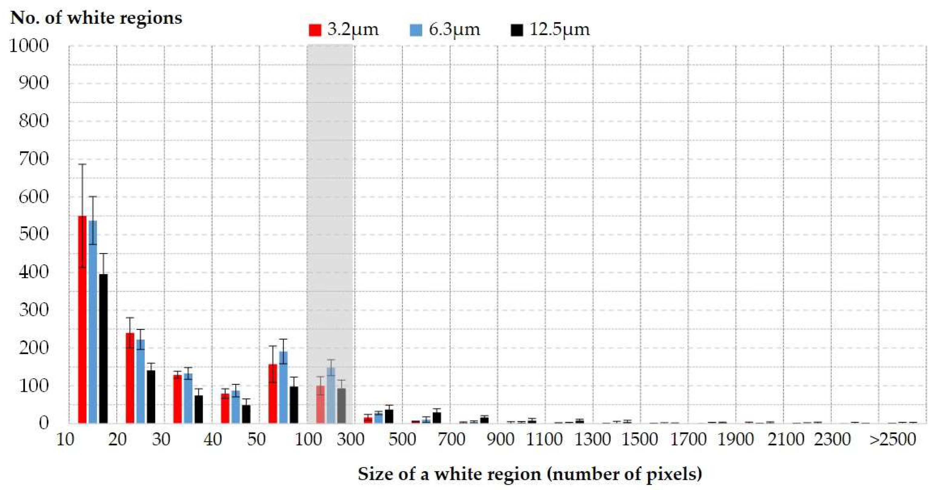
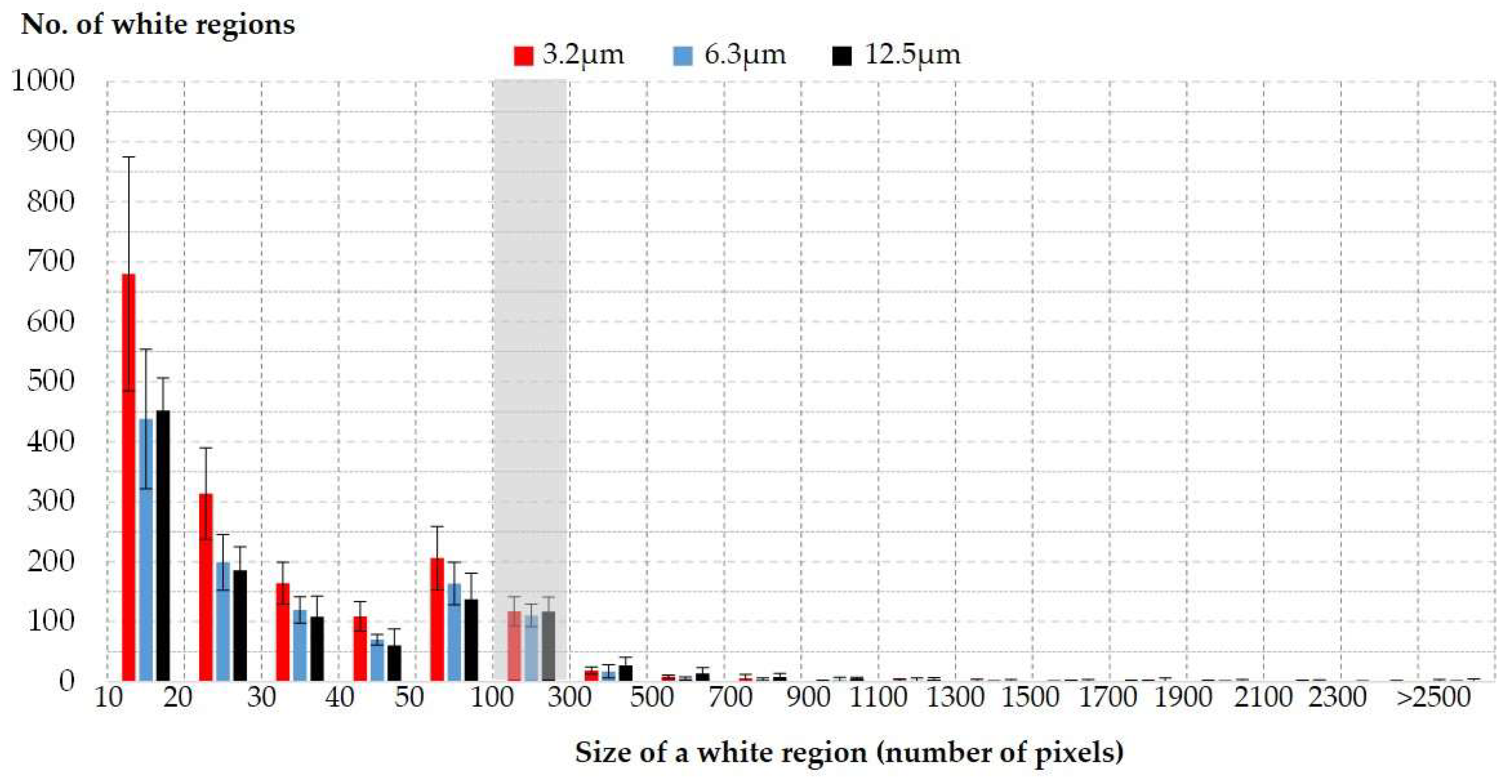
Figure 9 and
Figure 10 present the size distributions of white regions in a binary image before filtering. The size was defined as the number of white pixels. Note that tiny regions, having fewer than ten pixels, were not taken into account. There existed more than 400 regions with a range from 10 to 20 pixels in size (this corresponded to about 40 percent of the total). In the figures, 50 white regions in a gray area were selected.
The same filter was applied to the binary images, and the filtered images are found in
Figure 7c,f,i,l and
Figure 8c,f,i,l. The white pixels of the filtered images were counted and the number of the pixels is presented in
Table 2. The number of white pixels on the filtered images tends to increase with increased arithmetic average roughness for both shot- and sand-blasted surfaces.
4. Discussion
In order to analyze a relation between the average size of white regions and the arithmetic average roughness, the numbers of white pixels presented in
Table 2 were interpreted with a one-way analysis of variance (ANOVA). In the one-way ANOVA, null hypothesis and alternative hypothesis were defined as.
Null Hypothesis (H0): There is no significant difference among three groups (numbers of white pixels) measured at each arithmetic average roughness (Ra) of blasted surfaces.
Alternative Hypothesis (H1): Statistically significant difference exists among the mean levels of the groups.
Table 3 and
Table 4 show the summary and the result of one-way ANOVA for shot- and sand-blasted surfaces, respectively. The summaries of the standard errors and the confidence intervals for each roughness level are shown (
Table 3(1) and
Table 4(1)). The standard error for shot-blasted surfaces was lower than that for sand-blasted surfaces. It is possible to compare the variability of data between shot- and sand-blasted surfaces: at the R
a values of 3.2 μm and 12.5 μm, the variances of shot blasting were greater than those of sand blasting, indicating that shot-blasting data maintained greater variability than sand-blasting ones. For shot blasting, there was no significant difference in variances among the three groups. Meanwhile, for sand blasting, the variance for Group 3.2 μm was almost at one-fifth the level compared with those of other two groups.
During the ANOVA test procedure, an F-statistic was produced, which was used to calculate a
p-value. The
p-value indicates whether there exists a difference in measured data groups or not. If the
p-value is lower than 0.05, the null hypothesis is rejected and the alternative hypothesis is accepted. As shown in
Table 3(2)) and
Table 4(2), the calculated
p-values were found to be 6.99 × 10
−9 for shot blasting and 1.64 × 10
−5 for sand blasting. This means that there existed statistically significant differences among the mean levels of the three measured groups (the numbers of white pixels measured at different roughness levels).
For the purpose of establishing the relation between the average size of selected white regions and the arithmetic average roughness, a curve fitting was employed.
Figure 11 shows the relation between the percentage of white pixels (P
w) in the filtered image and the arithmetic average roughness (R
a).
Figure 11 shows that it is possible to fit the data with a linear function; note that R-squared values for shot- and sand-blasted surfaces were found to be 0.9963 and 0.9844, respectively. The error bars represent 95 percent confidence intervals. There exists a difference between the two fitted curves for shot- and sand-blasted surfaces. Particularly, the slopes of the curves were found to be different. It could be identified that the type of abrasive gave rise to the difference. The fitted curves are informative for predicting the arithmetic average roughness of blasted surfaces in a given manufacturing process within a chosen range (from 3.2 μm to 12.5 μm); note that the curve should be re-calculated when light intensity and abrasive material are changed.
This proposed machine vision system can operate quickly without human error, compared with conventional methods such as a stylus profilometer [
14,
15] or manual comparison [
16]. Although a stylus profilometer provides accurate roughness measurement, a physical contact between a stylus probe and a target surface must be made. Continuous measurement brings about the wear of the stylus probe. Conventional laser or optical profilometers provide non-contact roughness measurement. However, it is difficult to use the profilometers in an actual blasting process due to cost. Thus, in practice, manual comparison is widely used, including tactile or visual perception with a sample comparator. However, this manual comparison gives rise to human error that can decrease the accuracy of surface roughness.
Further work needs to include the investigation of possible factors that affect the slope of the linear function. The proposed system was developed for shot- and sand-blasting processes at fixed magnification and light intensity conditions. For identifying actual feasibility in shot- and sand-blasting processes, it is necessary to perform a sensitivity analysis by changing capture parameters such as magnification and light intensity. In addition, other raw materials should be taken into account.
Other dry-type blasting cases, including blower, suction, and dry ice blasting, need to be taken into account in the future system.
Dry lubricants are often applied onto shot-peened surfaces in aerospace engineering. Thus, the future application of the system should include shot-peened surfaces having an Ra value lower than 3.2 μm.
5. Conclusions
In this article, a machine vision system was developed for measuring the arithmetic average roughness of shot- and sand-blasted surfaces. In the system developed in-house, grayscale images were captured at the microscale, and then the images were analyzed with a proposed algorithm using Otsu’s method. A binary image determined with Otsu’s threshold was filtered; that is, only white regions satisfying specific size conditions were extracted from the binary image. The sizes of extracted regions associated with the specular reflection of light were determined by counting the number of white pixels in the filtered image.
Blasted nickel alloy plates with Ra values of 3.2 μm, 6.3 μm, and 12.5 μm were prepared with two types of abrasives: shot and sand. The system captured four surface images for each Ra level, so twelve surface images were analyzed for each blasting.
A one-way analysis of variance (ANOVA) was used to identify the relation between the size of the selected white regions (number of selected white pixels) and the arithmetic average roughness of blasted surfaces. It was found that the size of the regions was related to the arithmetic average roughness of shot- and sand-blasted surfaces within the chosen Ra range.
For the purpose of discovering a mathematical relationship between the average size of selected white regions and the arithmetic average roughness, curve fitting was employed. It was identified that the percentage of selected white pixels can be expressed as a linear function of the average roughness of both shot- and sand-blasted surfaces. There exists a difference between the slopes of the linear function of the shot- and sand-blasted surfaces. The type of abrasive was one factor bringing about such difference. Further work needs to include an investigation of possible factors affecting the slope of the linear function.
The proposed system was developed for the quality inspection of near-white metal blasting with shot and sand abrasives. Before applying the actual quality inspection process, the system was evaluated at a fixed magnification and under constant light intensity conditions. For identifying actual feasibility in shot- and sand-blasting processes, it is necessary to perform a sensitivity analysis by changing capture parameters such as magnification and light intensity. In addition, other raw materials and dry-type blasting, including blower, suction, and dry ice blasting, need to be taken into account in the future system. Dry lubricants are often applied onto shot-peened surfaces in aerospace engineering. Thus, the future application of the system should include shot-peened surfaces having a lower Ra value than 3.2 μm.
When a blasted surface with unknown roughness is given, it is possible to predict the arithmetic average roughness on the basis of the relationship within the range from 3.2 μm to 12.5 μm in Ra. Considering that this machine vision system can provide faster surface roughness measurement and can be built at lower cost than conventional methods, it could be used in the quality inspection process of shot and sand blasting.


