Article

Research on the Sealing Performance of Segmented Annular Seals Based on Fluid–Solid–Thermal Coupling Model

1
Aeronautical Engineering Institute, Civil Aviation University of China, Tianjin 300300, China
2
Aeronautical Mechanical & Electrical Engineering Institute, Chongqing Aerospace Polytechnic, Chongqing 400021, China
3
Sino-European Institute of Aviation Engineering, Civil Aviation University of China, Tianjin 300300, China
4
AECC Hunan Aviation Powerplant Research Institute, Zhuzhou 412002, China
5
Science and Technology on Helicopter Tranmission Laboratory, Zhuzhou 412002, China
*
Author to whom correspondence should be addressed.
Lubricants 2024, 12(12), 407; https://doi.org/10.3390/lubricants12120407
Submission received: 5 November 2024 / Revised: 20 November 2024 / Accepted: 20 November 2024 / Published: 22 November 2024
(This article belongs to the Special Issue Mechanical Tribology and Surface Technology)

Abstract

:
High-speed segmented annular seals are often subjected to friction and wear, and the groove design on the sealing surface can effectively suppress this loss. For the purpose of improving the sealing performance, the segmented annular seal models of three structures are established, and the accuracy of the calculation model is verified by comparing with the previous results. Through fluid–solid–thermal coupled analysis, the flow field characteristics, opening characteristics, and leakage characteristics of the segmented annular seal under high working condition parameters were studied. The results show that the setting of the shallow groove forms the hydrodynamic effect by squeezing and hindering the flow of fluid in the clearance. The increase in rotational speed and pressure difference can promote the increase in the opening force, while the temperature has no significant effect on the opening of the seal. Seals with ladder-like grooves have the best opening performance, and seals without shallow grooves are already difficult to open under conditions of high pressure difference and large spring forces. Temperature and pressure difference are the main factors affecting the leakage of the seal, while the influence of the rotation speed is small. When the sealed pressure increases from 0.15 MPa to 0.4 MPa, the maximum increase in the leakage of the seal with specific groove design is 4.657 times the original. As the temperature rises from 420 K to 620 K, the maximum decrease in the three structures is up to 22.9%. Among the seals of the three structures, seals with ladder-like grooves have medium leakage. This research will contribute to the improvement of research methods for the sealing performance of segmented annular rings, especially for the evaluation of groove design and opening characteristics.

1. Introduction

An aeroengine contains various rotating machine systems that have a large number of dynamic–static contact surfaces, leading to significant leakage issues. Therefore, efficient sealing devices are required to reduce the high-pressure fluid leakage of the engine on the mechanical contact surfaces. It has been shown that the performance of the sealing devices in the aeroengine has a significant impact on the efficiency of engine components and the overall operation of the engine [1]. Meanwhile, with the rapid advancement of the aviation industry, aircraft engines are evolving toward higher speeds, higher temperatures, and greater pressure differentials. Consequently, the operating conditions for dynamic seals in high-parameter aircraft engines are becoming increasingly stringent, and traditional sealing methods can no longer meet the requirements. As an advanced seal with excellent performance, segmented annular seals have garnered widespread attention.
The history of segmented annular seals dates back to the 1970s when NASA [2] invented the segmented annular seal based on the face seal. It is a type of radial seal that has self-compensation capabilities under high working condition parameters. Through the design of a split ring, the torque of the segments during wear is reduced, and the friction of the segments is uniform. Compared to traditional floating ring seals, segmented annular seals have lower leakage and higher stability [3,4,5]. Due to the excellent performance of the segmented annular seals, the seals have been widely used in the main bearing chamber seal of aeroengines. However, the friction and wear between the inner surface of the segments and the runway have increasingly constrained the seal’s service life. To improve the sealing performance, a segmented annular seal with shallow grooves on the inner surface was developed [6]. This sealing device makes full use of the hydrodynamic effect, enabling high-speed and frictionless sealing, significantly enhancing the reliability and service life of the seals. The balance between achieving optimal sealing clearance and minimizing the risk of rotor rubbing has become a challenge that scholars need to address.
The research methods for segmented annular seals initially focused on independent fields and experiments. Oike et al. [7] solved the opening force and leakage rate of the graphite seal with Rayleigh ladder-like grooves based on the incompressible fluid Reynolds equation, and the results were verified through experiments. Arghir et al. [8] conducted a numerical analysis to study the effects of operating parameters and geometric parameters on seal leakage and frictional power consumption. The results indicated that the depth of the shallow grooves is the primary factor affecting the seal’s leakage rate, while the influence of groove length and groove width are inconspicuous. Bai et al. [9,10] studied the hydrodynamic characteristics of shallow grooves of the segmented annular seals based on gas lubrication theory. The finite difference method was used to analyze the influence of operating parameters and groove geometric parameters on the gas film pressure and leakage rate. The results showed that increasing the groove width, groove number, and groove depth enhanced the hydrodynamic effect of the seal. Additionally, as the ratio of groove width to groove radius increased, the dimensionless average pressure initially increased and then decreased. Li et al. [11] studied the variation in the leakage of seals by combining numerical calculations with experimental methods, focusing on key parameters such as pressure, rotational speed, and the circumferential spring preload of the seal. With the advancement of technology, the limitations of the independent field model are becoming more and more significant, and the research based on it cannot meet the needs of scholars. Wang et al. [12] established a model for the static and rotordynamic characteristics based on the local differential quadrature (LDQ) method. The results show that structural parameters of the shallow grooves are the key parameters that influence the lift force, stiffness coefficient, and damping coefficient of segmented annular seals, while have little influence on the leakage.
Under the action of high temperature and high pressure airflow, the segments will undergo obvious deformation [13]. To further investigate the performance of the seal under high parameter conditions, the multi-physics coupling model has become an effective method. Yun et al. [14] considered the uneven distribution of spring force and performed structure–heat coupling simulation calculations on the main components of the circumferential sealing device. The results showed that the uneven distribution of spring force leads to an increase in clearance and leakage. Chen et al. [15] constructed a fluid–solid coupling model whose fluid domain included the main seal between the segments and the runway. The main mechanical parameters affecting the segments’ deformation were analyzed by using orthogonal experimental design. Furthermore, the influence of joint shapes, joint clearances, and the groove profile of the auxiliary seal interface on the deformation of segments were discussed. Ma et al. [16] considered the influence of the temperature field and established numerical calculation models for the solid domain and flow field of segmented annular seals. By optimizing the parameters of the shallow grooves based on numerical analysis, the seals achieve stable frictionless operation at high speed and maintain a low leakage rate, resulting in the reduction of the temperature rise and the frictional wear of the seal. Yan et al. [17] proposed a fluid–solid–thermal coupling model that included the auxiliary seal between the segments and the case. The characteristics of the flow field, temperature field, and structural field of the segment annular seals were analyzed.
In recent years, for the purpose of improving the performance of the segmented annular seal, several studies on structural optimization design have been made. Arghir et al. [18,19,20] are devoted to the development of a kind of rotor micro-textured segmented annular seal and they have done various kinds of research. It was found that the textured rotor can increase the leakage, while decreasing the torque and temperature. Fan et al. [21] established a numerical model based on two-phase flow theory to analyze the flow field characteristics and leakage performance of three types of rotor micro-textured segmented annular seals. The results showed that the helical groove structure exhibited the best sealing performance and hydrodynamic effect, effectively reducing the friction and wear of the graphite segments. Ren et al. [22] designed a kind of segmented annular seal with triangular grooves and established the numerical solution model of fluid–solid–thermal coupling. Through the calculation under the condition of high working condition parameters, it is found that the seal with triangular grooves has a large opening force and a small leakage, and the sealing performance is good.
According to the summary of the literature, the current simulation study of segmented annular seals mainly focuses on the independent field model of flow or structure. Some progress has been made by the utilization of multi-physics coupling models, while the established models are relatively simple. The influence of segment deformation on the opening performance and leakage characteristics under fluid–solid–thermal coupling action is not considered comprehensively. Meanwhile there is still room for further optimization of the sealing structure. In this paper, various forms of fluid–solid–thermal coupling models of the segmented annular seal are constructed, and the flow field characteristics, opening characteristics, and leakage characteristics without grooves, with rectangular grooves, and with ladder-like grooves under different working conditions are analyzed. Finally, the structure with the best performance is selected. The purpose of the study is to provide a basis for the design and optimization of segmented annular seals with a high linear speed and large pressure difference, and lay a foundation for the improvement of the sealing performance of aeroengines.

2. Numerical Model

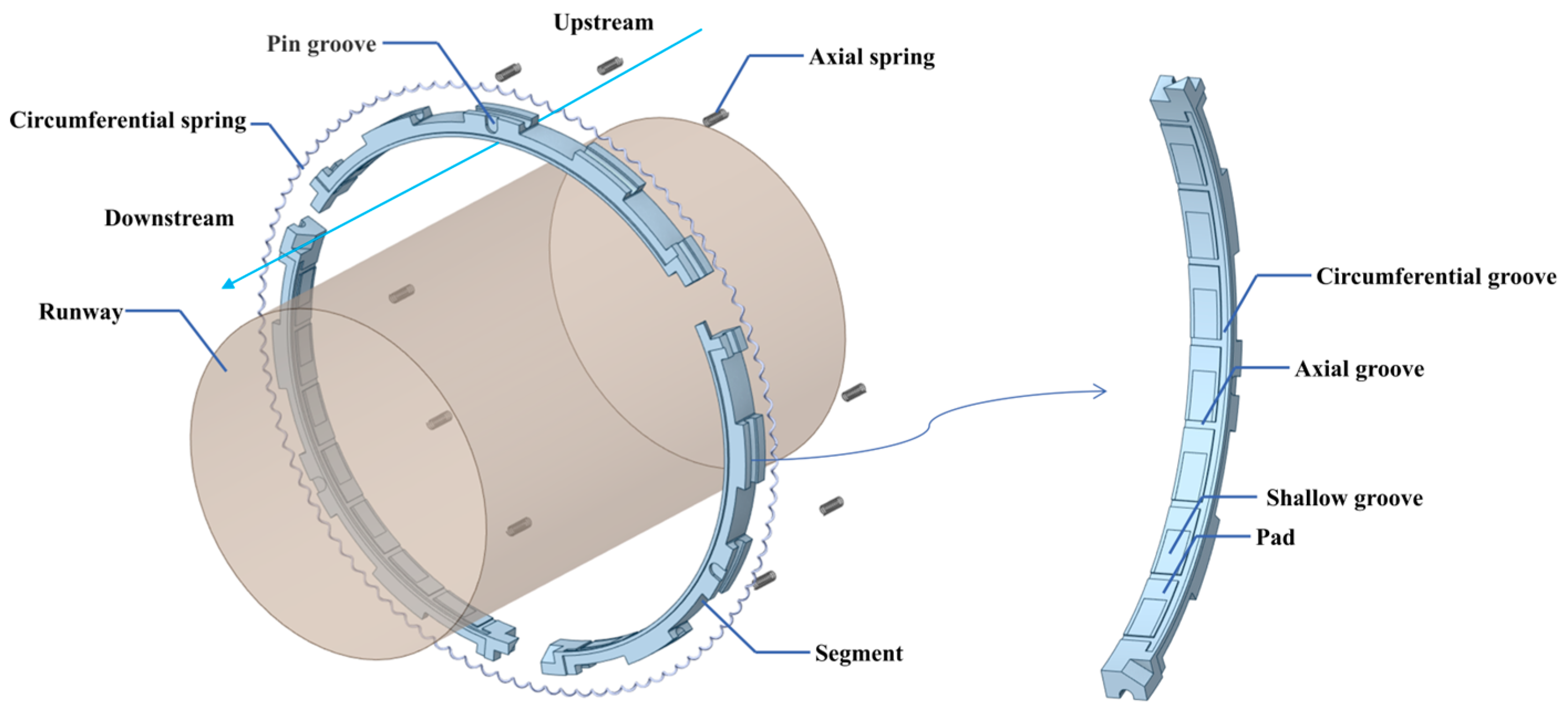
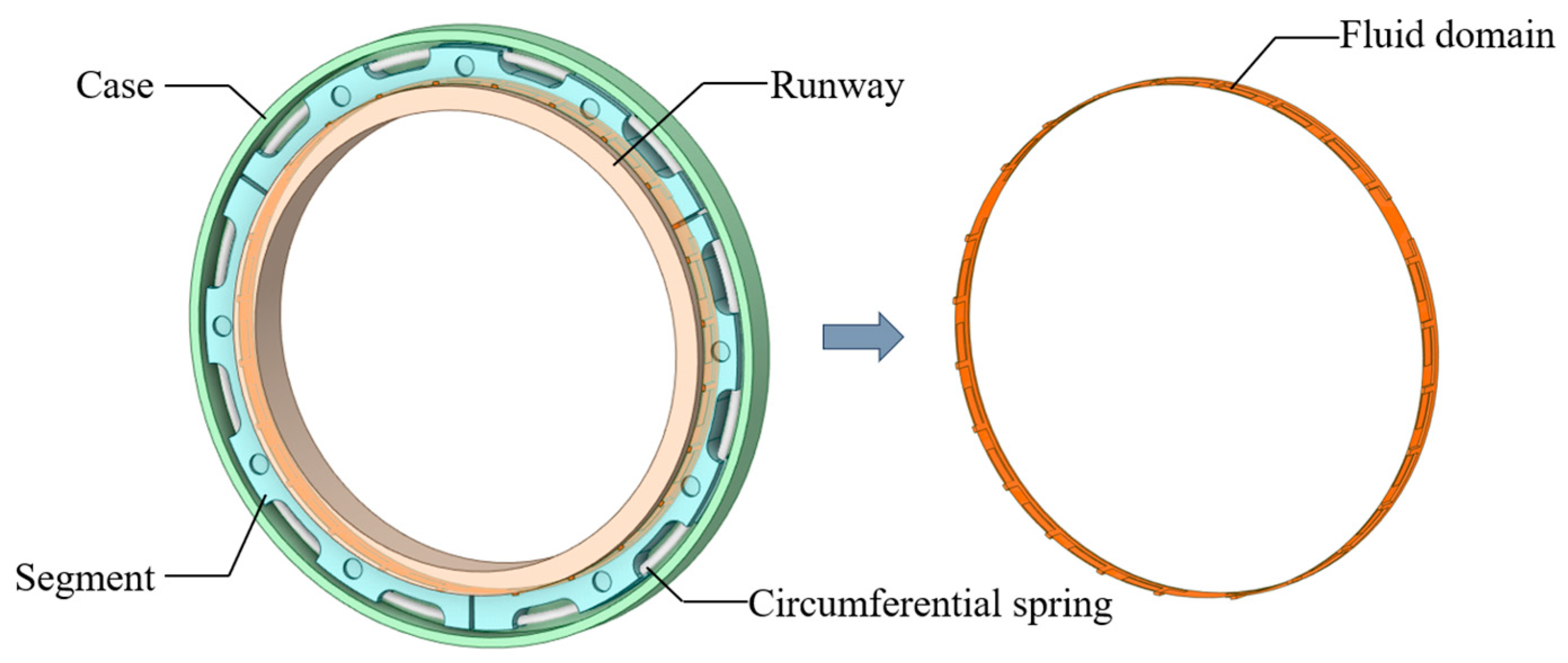
2.1. Working Principle

2.1.1. Theoretical Model

A typical segmented annular seal with shallow grooves is shown in Figure 1; it is composed of several graphite segments, a case, a circumferential spring, and axial springs. In the radial direction, the segments are pressed by the circumferential spring against the rotor. To prevent the radial displacement of the segments, the compressed springs press the segments to the case. The segments are connected in turn through lap joints. There is a certain circumferential assembly clearance between the joints to compensate for the wear and manufacturing errors of the segments during the working process. The inner surface of segments and the outer surface of the runway form the main seal, which is the main leakage path of the fluid.

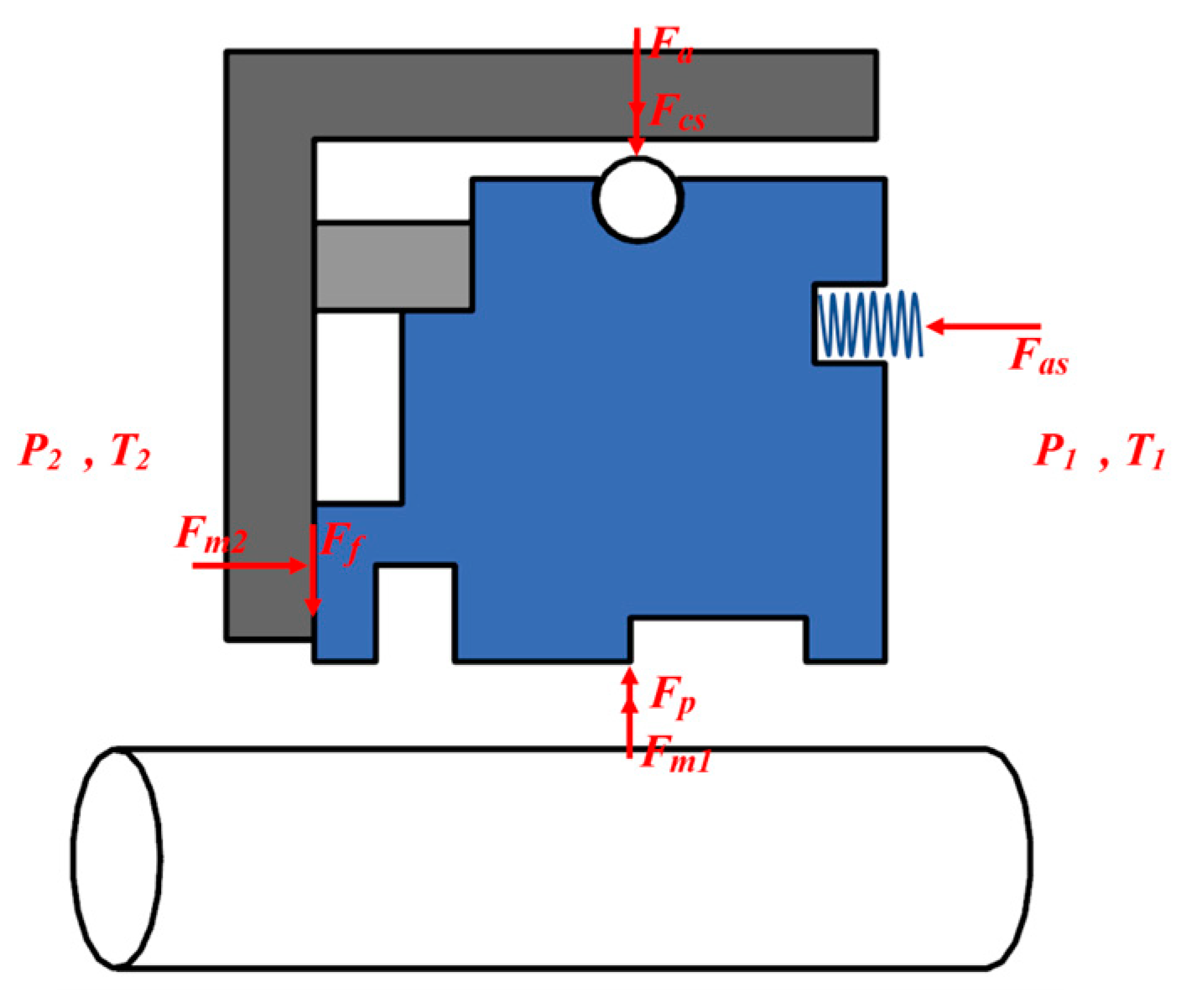
2.1.2. Force Analysis

The force schematic of the segments is shown in Figure 2. In the axial direction, F a s is the axial spring force, F m 2 is the force of the casing on a segment. In the radial direction, F m 1 is the runway support, F p is the dynamic pressure buoyancy, F c s is the circumferential spring force, F a is the circumferential closing force generated by the medium, and F f is the friction of the casing on a segment, where F a + F c s + F f is known as the opening resistance, and F p is known as the opening force.
Segments in a steady state satisfy the following relations:
F a + F c s + F f = F p + F m 1
F f = μ F m 2
where µ is the friction coefficient and the value is taken as 0.1 in this study.
The opening process of a segmented annular seal is shown in Figure 3. Initially, when the rotor is at rest, the segments are pressed against the runway by the opening resistance. The opening force increases and the runway support decreases as the rotation speed increases. When the runway support force drops to zero, the seal opens. When the seal clearance increases, the dynamic pressure effect is weakened, the opening force decreases, and the seal tends to close; when the clearance decreases, the dynamic pressure effect increases, the opening force increases, and the seal tends to open. Ultimately, a dynamic balance of opening force and opening resistance is achieved with a steady clearance.

2.2. Method of Analysis

2.2.1. Method of Flow Field Characteristics Analysis

In this study, the fluid in the clearance is considered as an ideal compressible gas, and the governing equations are shown as the following equation [23]:
p t + U ρ + ρ U = 0 ρ D U D t = ρ f + ( F i j e i e j ) ( E + U 2 2 ) t + U ( E + U 2 2 ) = f U + q ˙ + λ p Δ t t e m p + 1 ρ ( U F i j e i e j )
where p is the pressure on the fluid microelement, t is the time, U is the velocity vector, ρ is the density, F i j is the component of stress tensor, e i and e j are the components unit stress, E is the internal energy, q ˙ is the generation in unit mass of fluid micro-mass, λ is the Fourier thermal conductivity, and Δ t t e m p is the temperature gradient.
The fluid in the clearance is set as Newtonian fluid, which maintains a constant viscosity regardless of the applied shear rate, and its constitutive equation is as follows [24]:
P i j = p δ i j + 2 μ ( S i j 1 3 S k k δ i j ) S k k = S 11 + S 22 + S 33
where P i j is the component of viscous stress tensor, δ i j is the isotropic part of stress, U is the velocity vector, μ is the viscosity, and S i j is the component of deformation rate tensor.
The state of fluid flow in the sealing clearance can be judged by the Reynolds number obtained from the following relation [23]:
Re = 2 ρ v h μ
where h is the thickness of seal clearance.
The Reynolds numbers of the fluids involved in this study were calculated to be small and in accordance with the specifications for the use of laminar flow models. Due to the high operating speed of the runway, the groove structure of the main sealing surface is more complex, and the fluid is very prone to turbulence and vortex. Therefore, the k ε model is used in this study. The k ε model takes into account the effects of a low Reynolds number and shear flow corrections, which can better handle near-wall motions [25].

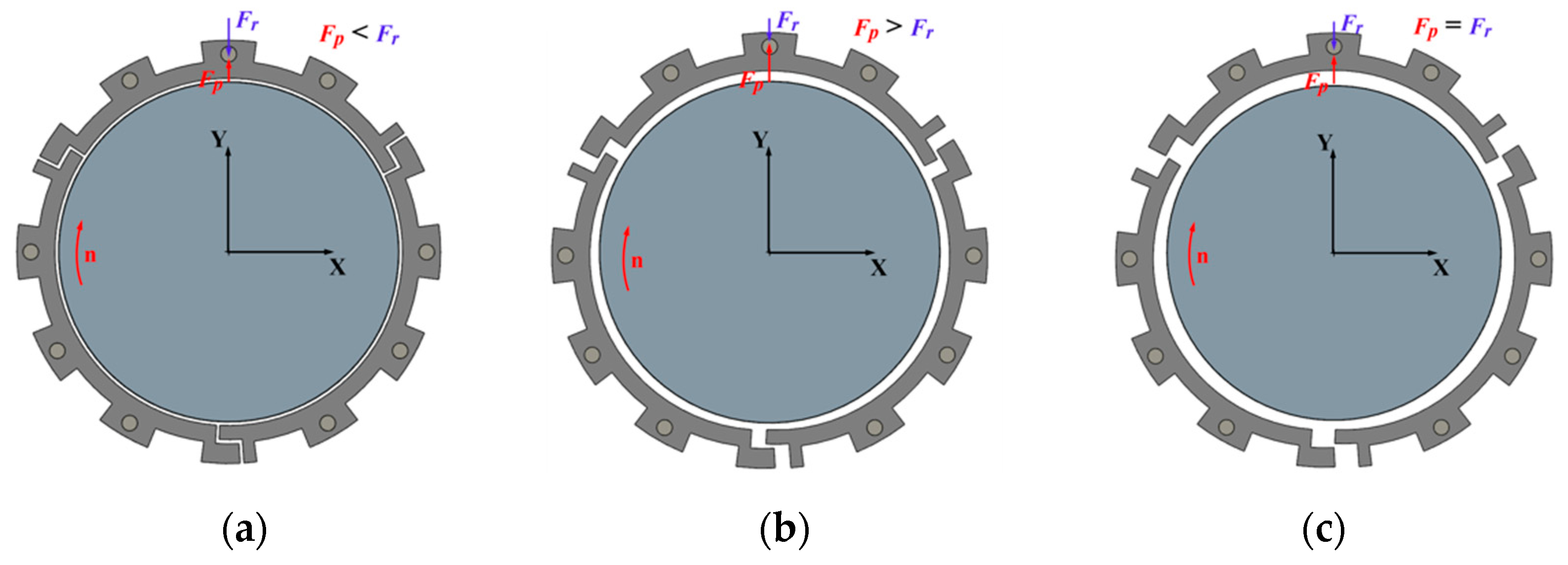
2.2.2. Method of Opening Characteristics Analysis

In order to clearly evaluate the opening characteristics of a segmented annular seal, the study of the opening characteristics of a segmented annular seal is divided into two parts: opening force calculation and opening speed calculation. Opening force is the numerical expression of the dynamic pressure effect of clearance, and the opening rotation speed is the runway speed that makes the segments float. A segmented annular seal with excellent performance requires a small opening resistance and a low opening rotation speed, so as to ensure that the seal can open even at a low working rotation speed and avoid the friction and wear of the segments.
The opening force can be calculated by the average pressure; the method is shown as follows in Equation (6) [26]:
p a v = 1 A p d A = 1 A i = 1 n p i A i F P = p a v S
where p a v is the average pressure acting on the inner surface of the segments and S is the area of the inner surface.
The calculation of the opening rotation speed must first determine the clearance when the segments are in contact with the runway. The concept of contact gas film thickness is introduced in this paper [27,28]. For whether the two ends are in contact, the criteria are as follows: when the minimum gas film between the two sides is greater than or equal to the thickness of the contact gas film, it is considered that the two sides are not in contact; otherwise, the two sides are in contact. For a contact surface as shown in Figure 4, the definition of the contact air film thickness is related to the roughness of the sealing face, which can be expressed as follows:
h c = 3.75 R 1 2 + R 2 2
where R 1 and R 2 represent the roughness of the inner surface of the seal ring and the outer surface of the runway, with both R 1 and R 2 taken as 0.2 μm in the study.
The calculation method of the opening rotation speed is shown below.
  • Establish the fluid domain model according to contact gas film thickness;
  • Calculate the opening resistance according to structural parameters, Equations (1) and (2);
  • Set the opening rotation speed until the opening force is slightly larger than the opening resistance.

2.2.3. Method of Leakage Characteristics Analysis

The influence of segment deformation should be considered in the analysis of leakage characteristics. The solid domain focuses on the segments and runway affected by external forces, temperature, and rotation speed. The equilibrium state of the solid domain under fluid pressure can be solved by the following equation [29]:
M u ¨ + C u ˙ + K u = F
where M is the mass matrix, C is the damping matrix, K is the stiffness matrix, u ¨ , u ˙ , and u are the acceleration vector, velocity vector, and displacement vector, respectively, and F is the load vector generated by the fluid in the clearance.
Thermal deformation is a key factor affecting the movement of the segments, which can be solved by Equation (9) as follows:
f = α T T
where α T is the coefficient of thermal expansion.
For the fluid–solid–thermal coupling interface, the stress, deformation, heat flow density, and temperature of the solid and fluid should be satisfied when equal, and the fluid–solid–thermal coupling control equations are as follows [17]:
τ f n = τ s n d f = d s q f = q s T f = T s
where n is the normal direction of the coupling surface, τ f and τ s are the stresses on the respective coupling surfaces of the fluid and solid domains, and d f and d s are the deformations on the respective coupling surfaces of the fluid and solid domains.
Through the fluid–solid–thermal coupling calculation, the axial deformation of the solid domain can be obtained. Then, the new fluid domain is constructed. Since the hydrodynamic pressure exerted by the fluid domain on the solid domain is a variable varying with the clearance thickness, multiple iterations are required until the deformation of the segments converges. Finally, the leakage after convergence is extracted.

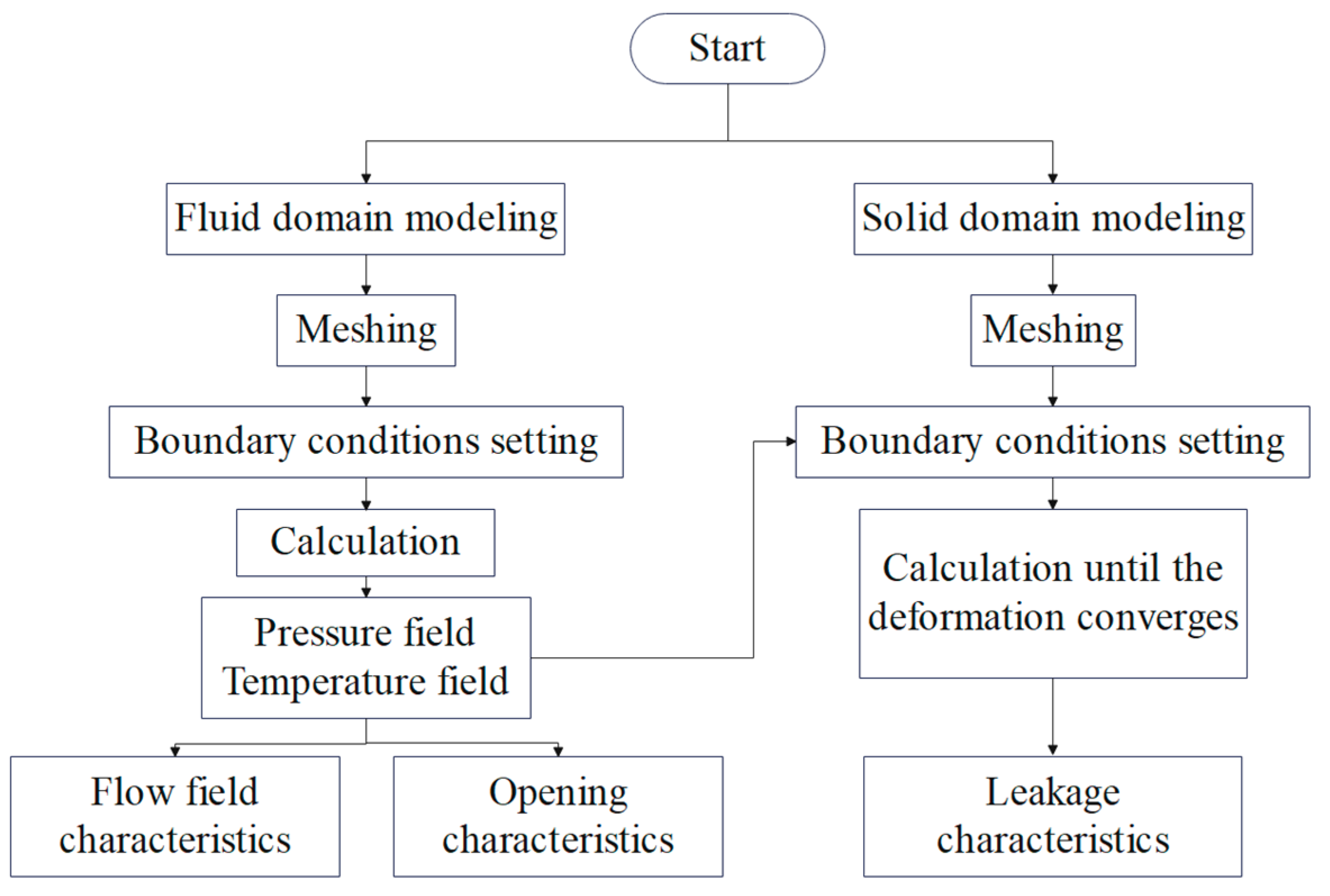
2.2.4. Fluid–Solid–Thermal Coupling Calculation Flowchart for a Segmented Annular Seal

This study starts from the fluid domain and carries out the flow field characteristics analysis of the influence of structural optimization on the clearance. Then, aiming at the opening force and opening rotation speed, the opening ability of the seal is quantitatively studied. At last, the leakage is calculated to represent the leakage characteristics. Through the study of these three characteristics, the performance of the seal can be analyzed comprehensively.
The flowchart of the three characteristics analysis is shown in Figure 5. By combining Fluent software and Ansys Mechanical module, the fluid–solid–thermal coupling model of the segmented annular seal is constructed in Ansys Workbench platform 2022R1. First, the fluid domain of the segmented annular seal is calculated to obtain the pressure field and temperature field; then, the flow field characteristics and opening characteristics are analyzed. The solid domain model is established and the opening resistance of the segments is calculated. Then, the pressure field and temperature field are used as boundary conditions to couple with the structural field by grid interpolation. Through iterative solutions until convergence, the calculation results of fluid–solid–thermal coupling can be obtained.

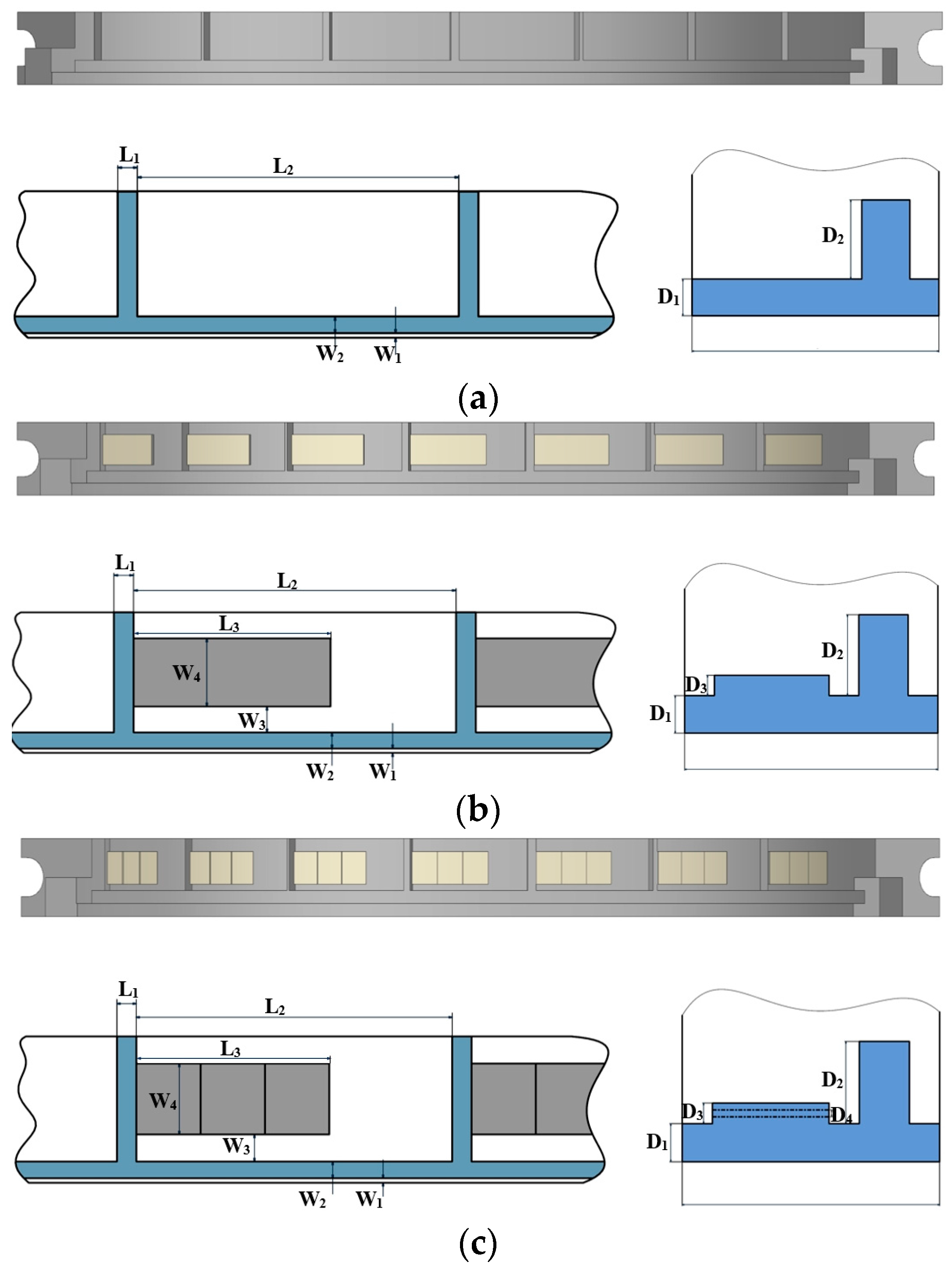
2.3. Calculation Model

The principal structure of the computational domain is depicted in Figure 6, encompassing a solid domain and a fluid domain. The solid domain contains segments and a runway and the fluid domain is the clearance between the segments and the runway. This paper focuses on the flow field characteristics and leakage characteristics of the seal, so the clearance at the lap joint is ignored.
Considering the operability of practical processing, the following shapes of grooves are introduced in this study: segments without shallow grooves, segments with rectangular grooves, and segments with ladder-like grooves. The three structures of the segments are shown in Figure 7. For the opening rotation speed calculation, the initial seal clearance is calculated by Equation (7), which is 1.06 μm. For the other research, the initial seal clearance is set as 3 μm to monitor a seal opening. The parameters of the shallow grooves are obtained from the literature [16] to ensure a good opening performance and to avoid a large effect of frictional wear on the grooves. The structural parameters are listed in Table 1.
Segments, as the main sealing part studied in this paper, are made of carbon graphite. The materials of the runway and case are structural steel. The material properties are shown in Table 2.

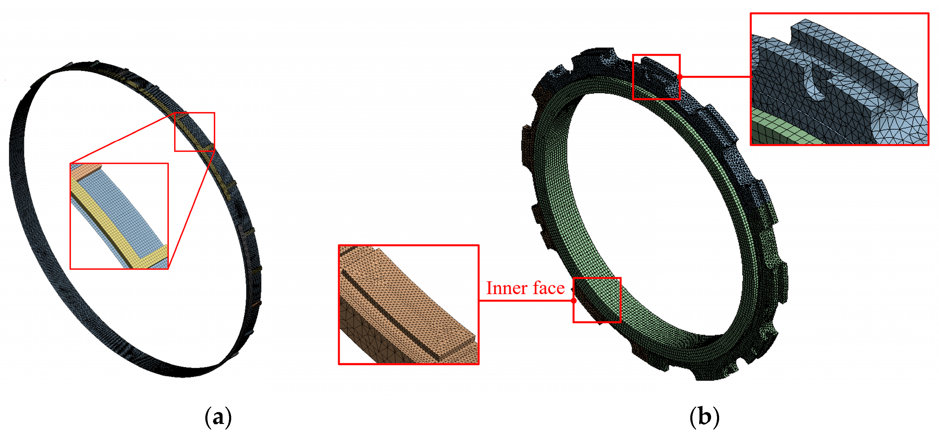
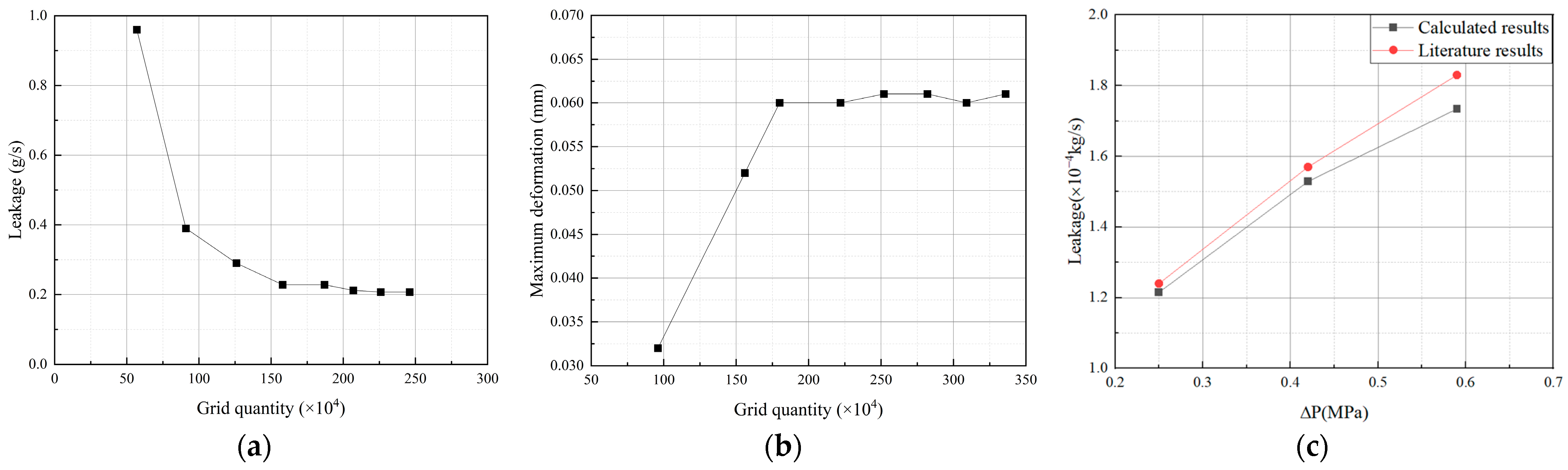
3. Grid Independence Verification and Model Verification

Taking the segmented annular seal without shallow grooves as an example, the specific mesh division is shown in Figure 8. The fluid domain grid is divided by sweep method and the obtained meshes are all hexahedral meshes. The inlet and outlet of the fluid film are set as the pressure inlet and pressure outlet, and the inner surface is set as the rotating wall. The solid domain is divided into tetrahedral meshes, whose boundary conditions are set as follows: the rotation speed is applied to the runway and the fixed support constraint is set on its inner surface. The spring force of the circumferential spring and the compressed spring are equivalent to the radial force and the axial force applied to the segments. The circumferential displacement constraint is applied equivalently at the anti-rotation pin.
Aiming at the leakage and the deformation of the segments, the grid independence verification analysis of the fluid domain and the solid domain is carried out. As can be seen in Figure 9a,b, the leakage begins to converge when the grid quantity of fluid domain reaches 1.87 million. The leakage begins to converge when the grid quantity of the solid domain reaches 1.8 million. In order to ensure the accuracy and efficiency of the calculation, the finalized grid quantity of the fluid domain and solid domain are 2.26 million and 2.52 million, respectively, where the error of leakage and maximum deformation is less than 1%.
In order to verify the accuracy of the calculation method, the segmented annular seal model and boundary conditions in reference [31] are used. According to the grid division method and boundary condition setting method above, the solution of the sealing flow field is carried out. As can be seen in Figure 9c, the calculated data are in good agreement with the literature data. The leakage deviation increases with the increase in pressure difference and the maximum deviation of leakage is 5.54%. The results indicate that the calculation method is feasible.

4. Results

4.1. Fluid Field Characteristics Analysis

The flow field pressure distribution of the fluid clearance directly determines the opening force of the seal, which in turn affects the sealing performance. Therefore, this study first investigates the effect of grooves on the fluid field characteristics of the segmented annular seal. The corresponding parameter values are shown in Table 3.

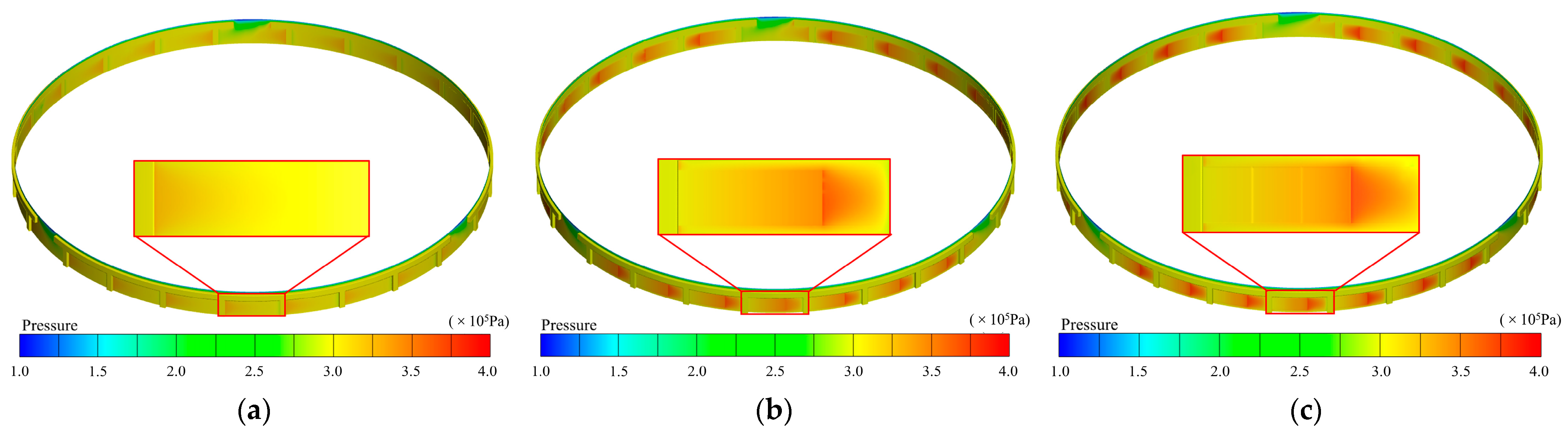
4.1.1. Pressure Distribution Cloud Analysis

Figure 10 shows the pressure distribution of the fluid domain of three segmented annular seals with an inlet pressure of 3 × 10⁵ Pa, and outlet pressure of 1 × 10⁵ Pa. From the figure, it can be seen that the pressure in most areas of the flow field is consistent with the inlet pressure setting. However, the pressure drops suddenly at the outlet, forming a low pressure zone. Due to the isolation effect of the lip, the development of a low pressure zone is restrained. As a result, the low pressure zone is concentrated in the clearance at the lap joint and less in other regions. The high pressure zone of the fluid domain is located between two axial grooves. Taking one of the pads and grooves as a unit for analysis, the pressure distribution is shown in Figure 11. From Figure 11a, it can be seen that the high pressure zone A1 is located at the end of the axial groove. This is because when the fluid is driven by the runway from the axial groove, the fluid is squeezed due to the decrease in the clearance, thus forming a slight high pressure zone. The maximum pressure is 0.322 MPa, which is only 7.33% higher than the inlet pressure. As Figure 11b demonstrated, the high pressure zone A2 of the flow field is located at the end of the rectangular groove, and the setting of the rectangular groove obviously enhances the hydrodynamic effect of the fluid. The maximum pressure is increased by 15.67% compared with the inlet pressure. It can be seen from Figure 11c that the multiple extrusions of the ladder-like groove can further enhance the hydrodynamic pressure effect; the maximum pressure of the flow field is increased by 22.67% up to the inlet pressure.

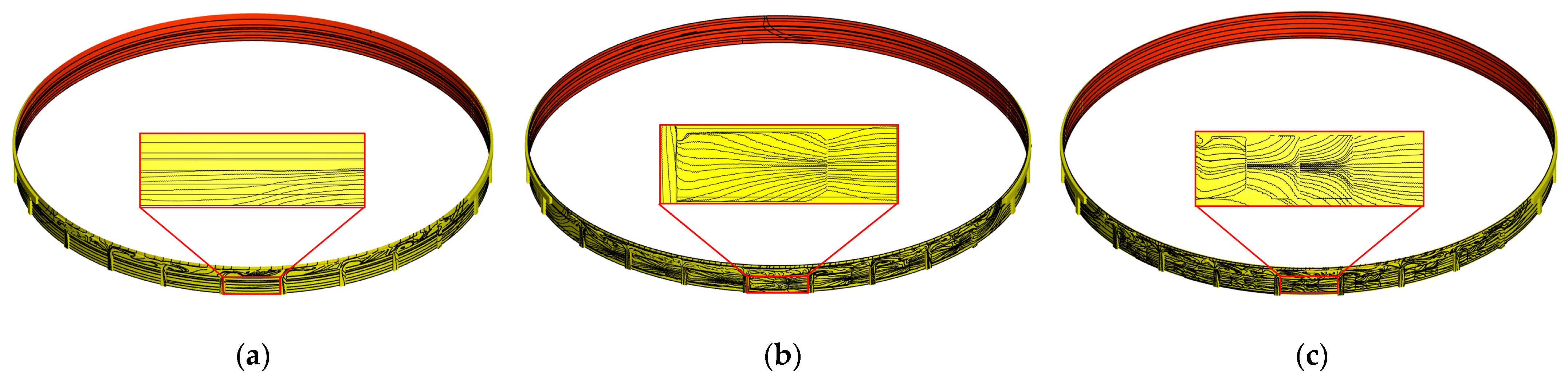
4.1.2. Velocity Distribution Cloud Analysis

The velocity distribution within the clearance with an inlet pressure of 3 × 10⁵ Pa and outlet pressure of 1 × 10⁵ Pa is given in Figure 12. The flow velocity gradually decreases in the radial direction from the inner surface to the outer surface. Compared with Figure 12a,b, it can be seen under the action of the rectangular grooves; the fluid flow is first concentrated in the shallow grooves and then diverges, thereby enhancing the hydrodynamic effect of the fluid by squeezing and hindering the flow. From Figure 12c, the setting of ladder-like grooves makes the fluid motion more complicated, and the squeezing effect between the fluids is also enhanced, thus further enhancing the hydrodynamic effect of the fluid.

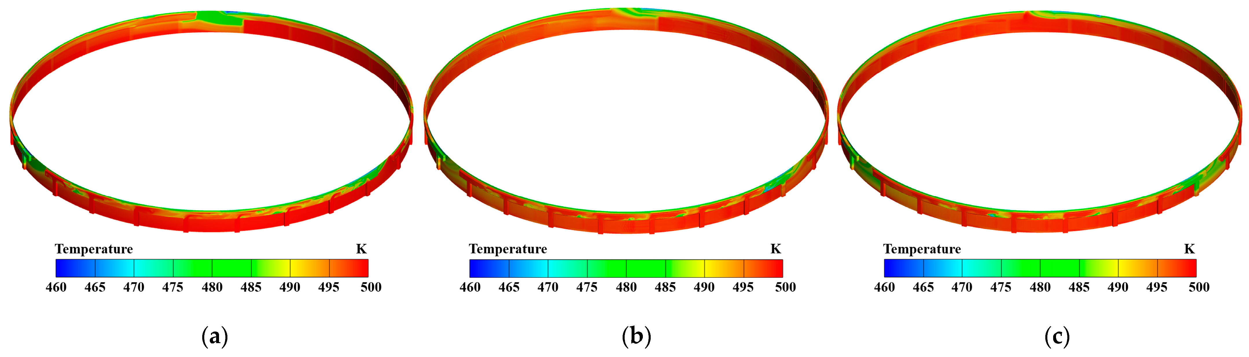
4.1.3. Temperature Distribution Cloud Analysis

Figure 13 shows the temperature distribution clouds of flow fields of three types of segmented annular seals. It can be seen that the overall distribution of the flow field temperature is relatively uniform. The temperature does not change significantly at the shallow grooves, and the low temperature zone is only generated near the outlet and at the lap joint. Therefore, it can be considered that the design of shallow grooves has no effect on the temperature of the flow field.
Overall, the design of the shallow grooves has a great influence on the pressure distribution in the fluid domain of a segmented annular seal. Among the three structures, the ladder-like grooves can effectively enhance the dynamic pressure effect and increase the maximum pressure. In order to quantitatively analyze the effect of the shallow grooves, the opening characteristics of the seal will be carried out.

4.2. Opening Characteristics Analysis

The opening characteristic analysis includes two parts: opening force calculation and opening speed calculation. The opening force is the key parameter of seal opening, which is affected by many operating parameters, and the opening rotation speed can be used to measure the overall opening characteristics of a segmented annular seal.

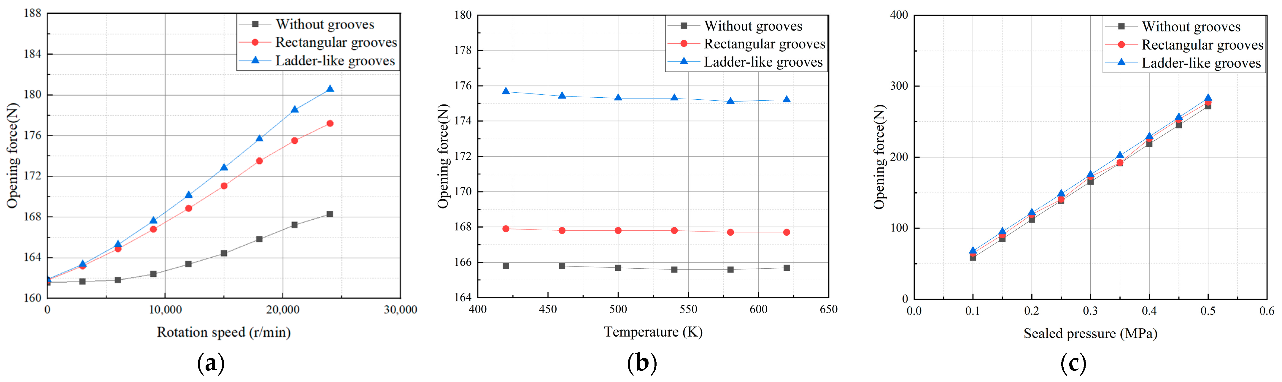
4.2.1. Effect of Operating Parameters on Opening Force

Figure 14a shows the effect of rotation speed on the opening force with a temperature of 500 K, inlet pressure of 3 × 10⁵ Pa, and outlet pressure of 1 × 10⁵ Pa. From the figure, it can be seen that the increase in rotational speed enhances the hydrodynamic effect, resulting in the increase in the opening force. When the rotation speed is zero, the opening force of the three types of seals is approximately equal, and as the rotation speed increases, the difference between the opening forces of the different groove types also increases gradually. At a speed of 18,000 r/min, the opening force of seals with rectangular grooves is increased by 1.32% compared to seals without grooves, and the opening force of seals with ladder-like grooves is increased by 4.6% compared to seals with rectangular grooves.
Figure 14b illustrates the effect of sealed pressure on the opening force with a rotation speed of 18,000 r/min, outlet pressure of 1 × 10⁵ Pa, and temperature of 300 K. It can be seen that the opening force increases linearly when the inlet pressure increases. The increase in pressure difference accelerates the fluid, which in turn allows more fluid to enter the shallow grooves and enhances the hydrodynamic effect. At a sealed pressure of 5 × 10⁵ Pa, the opening force of the seal with rectangular grooves increased by 2% compared with that of the segmented annular seal without grooves, and the opening force of seals with ladder-like grooves increased by 2.1% compared to seals with rectangular grooves.
Figure 14c demonstrates the effect of temperature on the opening force. It can be seen that the change in temperature had no effect on the seal opening force. When the temperature reached 620 K, the opening force of seals with rectangular grooves increased by 1.98% compared with that of seals without grooves, and the opening force of seals with ladder-like grooves increased by 2% compared with that of seals with rectangular grooves. Combined with the research in 3.1.3, it is considered that the temperature does not affect the opening characteristics of the seal.

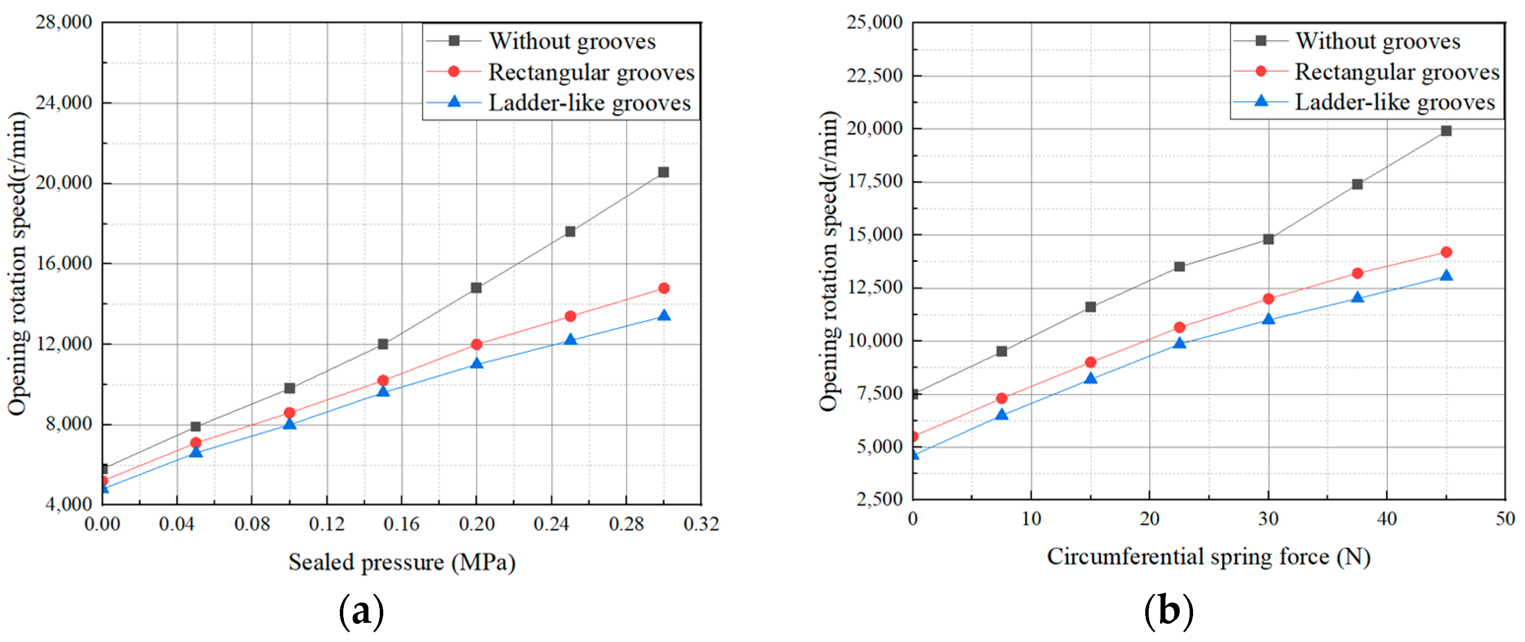
4.2.2. Effect of Sealed Pressure and Spring Force on Opening Rotation Speed

In this section, the opening rotation speed is calculated to evaluate the opening characteristics of a segmented annular seal. According to the previous study, the opening force varies considerably with sealed pressure, and the spring force is directly related to the opening resistance of the seal. Therefore, the effect of these two parameters will be studied.
Figure 15a shows the variation in opening rotation speed with the sealed pressure. It can be seen that the opening rotation speed increases as the sealed pressure increases. This is because both the opening force and opening resistance of the seal are affected by the pressure of the medium. With the increase in the pressure difference, the opening force and opening resistance of the seal increase accordingly. Due to the strong dynamic pressure effect of the segmented annular seal with ladder-like grooves, when the pressure difference rises from 0 to 3 × 10⁵ Pa, the opening speed of the seal only increases by 8600 r/min. However, the opening rotation speed of segmented annular seal without grooves reaches 20,560 r/min, which makes it difficult to open.
Figure 15b illustrates the variation in opening rotation speed with the circumferential spring force. Due to the spring force directly affecting the opening resistance of the seal, the opening rotation speed increases as the spring force increases. The opening rotation speed of the seal with rectangular grooves and with ladder-like grooves stays under 15,000 r/min; when the circumferential spring force reaches t45 N, the opening rotation speed of the seal with rectangular grooves increases by 8.8% compared to the seal with ladder-like grooves. Meanwhile the opening rotation speed of the seal without shallow grooves reaches 19,900 r/min, which makes it difficult to open.

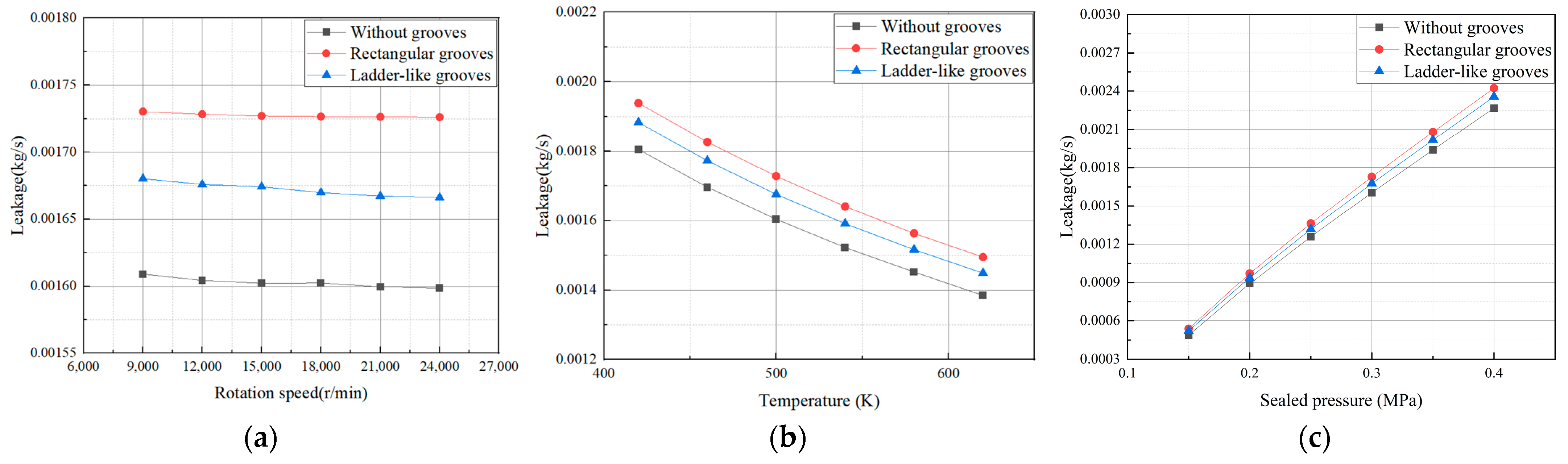
4.3. Leakage Characteristics Analysis

According to the previous study, segmented annular seals with shallow grooves have a larger opening force and increase the clearance, which is an important parameter in leakage characteristics. In this section, the fluid–solid–thermal coupling method is used to solve the sealing clearance and calculate the leakage. In order to make the seal easy to open and the deformation of the segment more obvious, the circumferential spring force is set to 7.5 N.
The deformation of three kinds of segments is shown in Figure 16. It can be seen that the deformation of the lap joint area of the segment is the largest and the deformation of the middle area is the smallest. According to the research in Section 4.1.1, there is a low pressure zone in the fluid domain below the lap joint, and the large pressure difference on both sides of the lap joint promotes its deformation. Due to the discontinuous characteristics of the joint interface, there exists a deformation difference of 2.4% at the lap joints on two sides of the segments. The total deformation of the three kinds of segments is almost the same, and the differences are not more than 1%. Then, the influence of the radial variation in the segments and the runway is considered to solve and analyze the leakage.
Figure 17a shows the effect of rotation speed on the leakage of a segmented annular seal. It can be seen that the leakage decreases slowly with the increase in rotational speed. This is because the sheer force of the runway to the sealed fluid increases when the rotation speed increases, which makes the fluid vortex phenomenon more intense and hinders the leakage of the fluid along the sealing clearance. Among the three structures, the leakage of a segmented annular seal with ladder-like grooves decreases the fastest with the rotation speed. When the speed reaches 18,000 r/min, the leakage of the seal with ladder-like grooves increases by 4.21% relative to the seal without grooves, and the leakage of the seal with rectangular grooves increases by 3.40% relative to seals with ladder-like grooves.
Figure 17b illustrates the effect of temperature on the leakage of a segmented annular seal. It can be seen that, with the increase in temperature, the leakage of seals with three kinds of shallow groove structure decreases. This is because with the increase in temperature, the viscosity of the fluid increases and the flow rate decreases. As the temperature rises from 420 K to 620 K, the maximum decrease in the three structures is up to 22.9%. At all temperatures, a segmented annular seal with rectangular grooves has the highest leakage. When the temperature reaches 620 K, the leakage of a seal with rectangular grooves increases by 4.62% relative to a seal without grooves, and the leakage of a seal with ladder-like grooves increases by 3.20% relative to seals with rectangular grooves.
Figure 17c demonstrates the effect of sealed pressure on the leakage of a segmented annular seal. Fluid flow is affected by pressure difference and always flows from high-pressure areas to low-pressure areas. As the pressure difference increases, the fluid flow is accelerated and the leakage increases significantly. The maximum increase in the leakage of the seal with a specific groove design is 4.657 times that of the original as the sealed pressure increases from 0.15 MPa to 0.4 MPa. When the pressure reaches 0.4 MPa, seals with rectangular grooves had increased leakage by 3.92% relative to seals without grooves, and seals with ladder-like grooves had increased leakage by 2.81% relative to seals with rectangular grooves.
It can be seen from Figure 17 that sealed pressure is the biggest influencing factor of seal leakage, while the influence of rotation speed is small. The seal without grooves has the lowest leakage and the seal with rectangular grooves has the highest leakage; the seal with ladder-like grooves can maintain medium leakage under the premise of good opening performance, which is proven to have good sealing performance.

5. Conclusions

This paper presented the sealing performance of three types of segmented annular seals, a fluid–solid–thermal coupling model is established to obtain the flow field characteristics, opening characteristics, and leakage characteristics of segmented annular seals. The effects of different shallow grooves and the condition parameters on the performance of segmented annular seals are systematically presented and discussed. Proper groove design can play a role in optimizing the opening performance of segmented annular seals by enhancing the opening force. However, better opening performance will also lead to larger leakage. The selection of the three types of seals can be determined according to the actual use requirements. The key conclusions are summarized as follows:
(1)
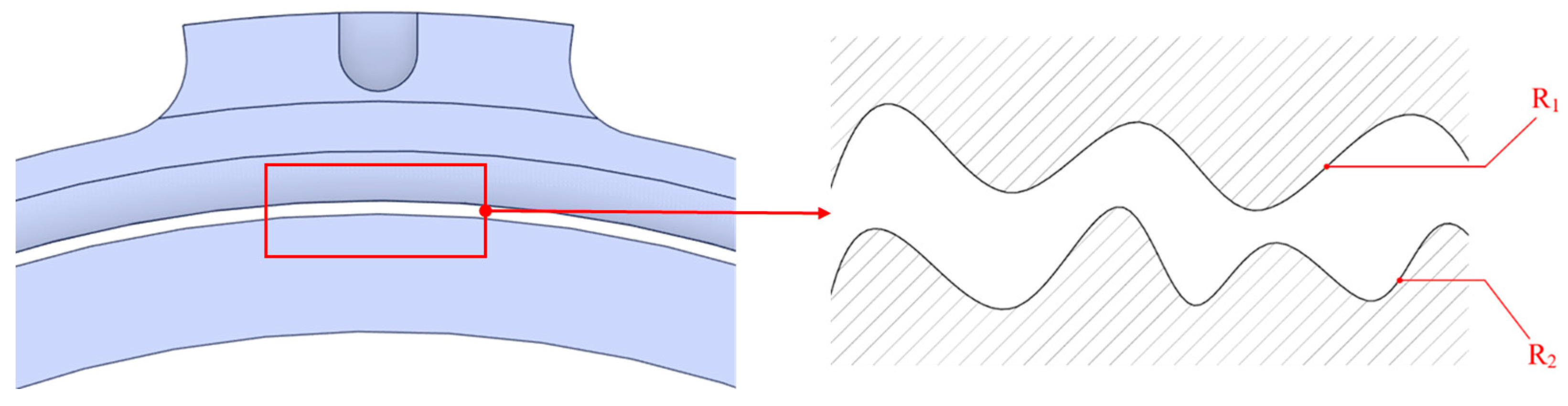
The setting of shallow grooves can effectively enhance the hydrodynamic effect by squeezing the fluid, and the enhancement effect of the ladder-like grooves is more significant than that of the rectangular grooves. However, the change in the groove type has little effect on the fluid temperature field.
(2)
For the seals with arbitrarily shaped shallow grooves in this paper, the sealed pressure has the most significant influence on the opening force of the seal; the greater the sealed pressure, the greater the opening force. The increase in rotational speed will also promote the opening force. However, the temperature has no obvious effect on the opening force.
(3)
Both the increase in the leakage pressure and the increase in the circumferential spring force will lead to an increase in the opening speed. Under the conditions of a high speed and a large spring force, the opening rotation speed of the seal without shallow grooves reaches around 20,000 r/min, which makes it difficult to open.
(4)
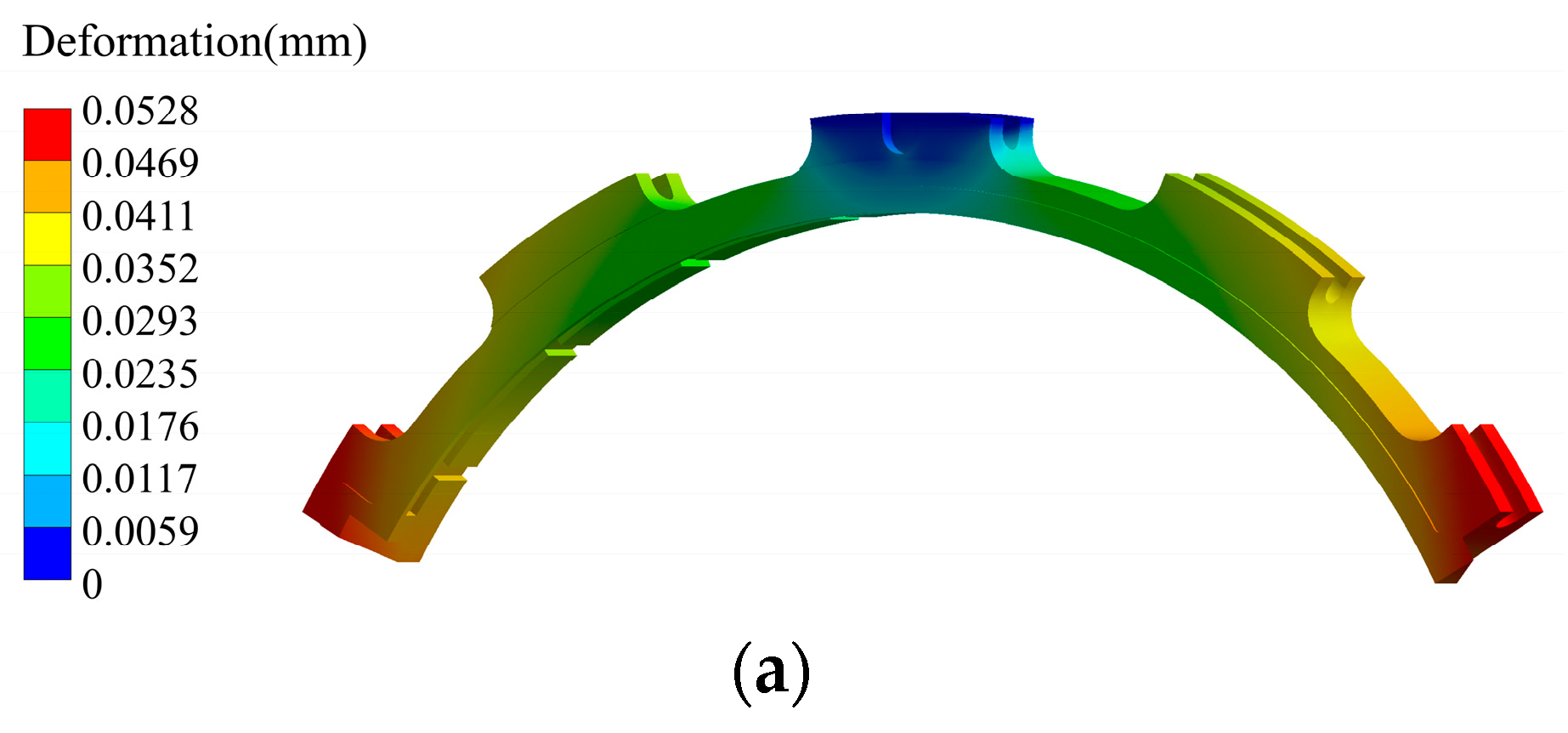
The total deformation of the segment increases gradually from the middle to the lap joint, while the shallow groove design has little effect on the total deformation.
(5)
An increase in the sealed pressure will lead to an increase in the leakage. When the sealed pressure increases from 0.15 MPa to 0.4 MPa, the maximum increase in the leakage of the seal with specific groove design is 4.657 times that of the original. Nevertheless, the leakage decreases with the increase in temperature and rotation speed.
(6)
Among the seals with three groove structures, the seal with ladder-like grooves has the best opening performance and is easy to open and maintain a frictionless seal under high parameter conditions. Compared to the seal without shallow grooves, the leakage of the seal with ladder-like grooves has only a small increase.
These results highlight the excellent sealing performance of seals with specific shallow grooves, and provide a method to analyze the sealing performance of segmented annular seals and an idea of structural optimization design. In order to further study and apply the segmented annular seals, there are two goals for future work: the establishment of more complex models and structural optimization design. In the establishment of the model, the influence of variable spring force can be considered to study the deformation and displacement of the segments under complex stress conditions. Meanwhile, fluid shear heat and friction heat need to be considered to comprehensively analyze the temperature field of the segments. In terms of structural optimization design, more grooves with excellent performance should be discovered on the basis of this study.

Author Contributions

Conceptualization, Z.H., L.J. and J.S.; Methodology, Z.H., L.J., H.W., Y.G., B.L. and S.Z.; Validation, L.J.; Data curation, L.J.; Writing—original draft, L.J.; Writing—review and editing, Z.H., L.J., J.S., N.L., H.W., Y.G. and W.L.; Visualization, L.J.; Supervision, Z.H., J.S. and N.L.; Funding acquisition, Z.H. All authors have read and agreed to the published version of the manuscript.

Funding

This research was funded by XX national science and technology major project, the Tianjin Municipal Science and Technology Bureau Science and Technology Plan Project grant number 23JCYBJC00110, the Fundamental Research Funds for the Central Universities grant number 3122023045, and the Chongqing Natural Science Foundation Project grant number CSTB2024NSCQ-MSX0388.

Data Availability Statement

The original contributions presented in the study are included in the article; further inquiries can be directed to the corresponding author.

Acknowledgments

The authors sincerely acknowledge the financial support mentioned above, which made it possible to continue this study.

Conflicts of Interest

Author J.S. and author N.L. are employed by the company AECC Hunan Aviation Powerplant Research Institute, and author W.L. is employed by the company Chongqing Aerospace polytechnic. The remaining authors declare that the research was conducted in the absence of any commercial or financial relationships that could be construed as a potential conflict of interest.

References

  1. Mayhew, E.; Bill, R.; Voorhees, W. Military Engine Seal Development-Potential for Dual Use. In Proceedings of the 30th Joint Propulsion Conference and Exhibit, Indianapolis, IN, USA, 27–29 June 1994. [Google Scholar]
  2. Ellen, R.; Mayhew, E. Air Force Seal Activity USA: Aero Propulsion & Power Directorate Wright Laboratory; NASA: Washington, DC, USA, 1980. [Google Scholar]
  3. Sorokina, N.E.; Redchitz, A.V.; Ionov, S.G.; Avdeev, V.V. Different exfoliated graphite as a base of sealing materials. J. Phys. Chem. Solids 2006, 67, 1202–1204. [Google Scholar] [CrossRef]
  4. Song, Y.Z.; Zhai, G.T.; Song, J.R.; Li, G.S.; Shi, J.L. Seal and Wear Properties of Graphite from MCMBs/Pitch-Based Carbon/Phenolic-Based Carbon Composites. Carbon Int. J. Spons. Am. Carbon Soc. 2006, 44, 2793–2796. [Google Scholar] [CrossRef]
  5. Baklanova, N.I.; Zima, T.M.; Boronin, A.I.; Kosheev, S.V.; Titov, A.T.; Isaeva, N.V.; Graschenkov, D.V.; Solntsev, S.S. Protective ceramic multilayer coatings for carbon fibers. Surf. Coat. Technol. 2006, 201, 2313–2319. [Google Scholar] [CrossRef]
  6. Burcham, R.E. High-Speed Cryogenic Self-Acting ShaftSeals for Liquid Rocket Turbopumps; NASA-CR-168194; NASA: Washington, DC, USA, 1983. [Google Scholar]
  7. Oike, M.; Nagao, R. Characteristics of a Shaft Seal System for the LE-7 Liquid Oxygen Turbopump. In Proceedings of the 31st Joint Propulsion Conference and Exhibit, San Diego, CA, USA, 10–12 July 1995. [Google Scholar]
  8. Arghir, M.; Mariot, A. Theoretical Analysis of the Static Characteristics of the Carbon Segmented Seal. J. Tribol. Trans. Asme 2017, 139, 062202. [Google Scholar] [CrossRef]
  9. Yang, H.W.; Bai, S.X. Gas Hydrodynamic Lubrication Performance of Split Floating Ring Seals with Rayleigh Step Grooves. J. Propuls. Technol. 2022, 43, 87–94. [Google Scholar]
  10. Bai, S.X.; Chu, D.D.; Ma, C.H.; Yang, J.; Bao, S.Y. Thermo-Hydrodynamic Effect of Gas Split Floating Ring Seal with Rayleigh step Grooves. Materials 2023, 16, 2283. [Google Scholar] [CrossRef]
  11. Li, Q.Z.; Li, S.X.; Zheng, Y.; Ma, W.J.; Zhuang, S.G. Sensitive parameters affecting performance of three-petal high-speed floating-ring seal. J. Beijing Univ. Aeronaut. Astronaut. 2020, 46, 571–578. [Google Scholar]
  12. Wang, S.; Sun, D.; Yang, Z.; Xu, W.F.; Zhao, H.; Wen, S.F. Investigation of static and rotordynamic characteristics of the segmented annular seals based on the differential quadrature method. Tribol. Int. 2024, 196, 109657. [Google Scholar] [CrossRef]
  13. Dahite, S.; Arghir, M. Thermogasodynamic Analysis of the Segmented Annular Seal. J. Tribol. 2021, 143, 072301. [Google Scholar] [CrossRef]
  14. Yun, R.D.; Chen, Z.Y.; Liu, Y.; Zhang, J.Y. Effects of Circumferential Spring Force Distribution on Sealing Performance of Circumferential Seal. J. Propuls. Technol. 2021, 42, 1361–1371. [Google Scholar]
  15. Chen, Z.X.; Peng, X.D.; Zhao, W.J.; Jiang, J.B. Deformation Characteristics and Control Strategies of a Dynamic Segmented Circumferential Seal. J. Tribol. 2023, 43, 143–156. [Google Scholar]
  16. Ma, R.M.; Zhao, X.; Li, S.X.; Chen, X.Z.; Zhao, H.C. Seal characteristics and friction and wear of dynamic pressure split floating ring seal. J. Propuls. Technol. 2022, 43, 210099. [Google Scholar]
  17. Yan, Y.T.; Wei, R.; Hu, G.Y.; Wang, F.C.; Zhang, L.J. Circumferential Seal Characteristics with Thermal-Fluid-Structure Multi-physics Field Coupling. J. Aeroengine Power 2020, 35, 305–317. [Google Scholar]
  18. Arghir, M.; Dahite, S. Numerical Analysis of Lift Generation in a Radial Segmented Gas Seal. In Proceedings of the ASME Turbo Expo 2019: Turbomachinery Technical Conference and Exposition, Phoenix, AZ, USA, 17–21 June 2019. [Google Scholar]
  19. Dahite, S.; Arghir, M. Numerical modelling of a segmented annular seal with enhanced lift effects. Mech. Syst. Signal Process. 2021, 152, 107455. [Google Scholar] [CrossRef]
  20. Fourt, E.; Arghir, M. Experimental Analysis of the Leakage Characteristics of Three Types of Annular Segmented Seals. J. Eng. Gas Turbines Power 2023, 145, 91–105. [Google Scholar] [CrossRef]
  21. Fan, R.F.; Zhao, H.; Ren, G.Z.; He, Y.; Sun, D.; Wang, X.Y. Influence of rotor micro-texture on oil leakage flow characteristics of circular graphite seal. J. Aerosp. Power 2024, 40, 20240102. [Google Scholar]
  22. Ren, G.Z.; Li, Y.P.; Sun, D.; Zhao, H.; Wen, S.F.; Wang, X.Y. Numerical Study on Leakage Characteristics of Dynamic Pressure Split Floating Ring Seal with Fluid-solid-thermal Coupling. J. Aeroengine Power 2022, 37, 114–123. [Google Scholar]
  23. Zhang, Z.S.; Cui, G.X. Fluid Mechanics, 2nd ed.; Tsinghua University Press: Beijing, China, 2015; pp. 108–146. [Google Scholar]
  24. Hu, T.X.; Zhou, K.; Wang, X.Y.; Ning, L.; Zou, H.Y. Numerical calculation and experiment on leakage characteristics of floating ring seal. J. Aerosp. Power 2020, 35, 888–896. [Google Scholar]
  25. Yakhot, V.; Orszag, S.A. Renormalization group analysis of turbulence: I basic theory. J. Sci. Comput. 1986, 1, 3–51. [Google Scholar] [CrossRef]
  26. Cai, Y. Research on Multi-Field Coupling and Sealing Performance of a Single Carbon-Graphite Circumferential Seal. Master’s Thesis, Sichuan University, Chengdu, China, 2021. [Google Scholar]
  27. Gulich, J.F. Centrifugal Pumps; Springer: New York, NY, USA, 2007. [Google Scholar]
  28. Peng, X.D.; Li, J.Y.; Sheng, S.E.; Yin, X.N.; Bai, S.X. Effect of surface roughness on performance prediction and geometric optimization of a spiral-groove face seal. Tribology 2007, 6, 567–572. [Google Scholar]
  29. Ren, H.; Li, F.C.; Du, L. Numerical calculation for the effect of FSI on marine propeller strength. J. Wuhan Univ. Technol. 2015, 39, 144–147. [Google Scholar]
  30. Zhou, H.N.; Li, G.Q.; Wang, C.F. Multi physical field coupling characteristics of high speed graphite seals. Lubr. Eng. 2024, 49, 49–59. [Google Scholar]
  31. Allen, G.P. Self-Acting Lift-Pad Geometry for Circumferential Seals-a Non-Contacting Concept; NASA-TP-1583C.1; NASA: Washington, DC, USA, 1980. [Google Scholar]
Figure 1. Segmented annular seal with enhanced lift effects.
Lubricants 12 00407 g001
Figure 2. Force schematic of a segmented annular seal.
Lubricants 12 00407 g002
Figure 3. Opening process of a segmented annular seal: (a) initial state of the seal; (b) rising state of the seal; and (c) balance state of the seal.
Lubricants 12 00407 g003
Figure 4. Contact surface of segments and runway.
Lubricants 12 00407 g004
Figure 5. Fluid–solid–thermal coupling calculation flowchart for a segmented annular seal.
Lubricants 12 00407 g005
Figure 6. Construction of segmented annular seals.
Lubricants 12 00407 g006
Figure 7. Structures of different segmented annular seals: (a) structure of a segmented annular seal without grooves; (b) structure of a segmented annular seal with rectangular grooves; and (c) structure of a segmented annular seal with ladder-like grooves.
Lubricants 12 00407 g007
Figure 8. Meshing of a seal without a shallow groove: (a) meshing of fluid domain of a segmented annular seal and (b) meshing of solid domain of a segmented annular seal.
Lubricants 12 00407 g008
Figure 9. Grid independence verification and accuracy verification: (a) fluid domain; (b) solid domain; and (c) accuracy verification.
Lubricants 12 00407 g009
Figure 10. Pressure distribution cloud of the whole fluid domain: (a) pressure distribution cloud of a segmented annular seal without grooves; (b) pressure distribution cloud of a segmented annular seal with rectangular grooves; and (c) pressure distribution cloud of a segmented annular seal with ladder-like grooves.
Lubricants 12 00407 g010
Figure 11. Pressure distribution cloud of a unit of the fluid domain: (a) pressure distribution of a segmented annular seal without grooves; (b) pressure distribution of a segmented annular seal with rectangular grooves; and (c) pressure distribution of a segmented annular seal with ladder-like grooves.
Lubricants 12 00407 g011
Figure 12. Velocity distribution cloud of a segmented annular seal: (a) velocity distribution cloud of a segmented annular seal without grooves; (b) velocity distribution cloud of a segmented annular seal with rectangular grooves; and (c) velocity distribution cloud of a segmented annular seal with ladder-like grooves.
Lubricants 12 00407 g012
Figure 13. Temperature distribution cloud of a segmented annular seal: (a) temperature distribution cloud of a segmented annular seal without grooves; (b) temperature distribution cloud of a segmented annular seal with rectangular grooves; and (c) temperature distribution cloud of a segmented annular seal with ladder-like grooves.
Lubricants 12 00407 g013
Figure 14. Effect of different condition parameters on opening force: (a) effect of rotation speed on opening force; (b) effect of temperature on opening force; and (c) effect of sealed pressure on opening force.
Lubricants 12 00407 g014
Figure 15. Effect of different parameters on opening rotation speed: (a) effect of sealed pressure on opening rotation speed and (b) effect of circumferential spring force on opening rotation speed.
Lubricants 12 00407 g015
Figure 16. Deformation of three kinds of segments: (a) deformation of a segment without grooves; (b) deformation of a segment with rectangular grooves; and (c) deformation of a segment with ladder-like grooves.
Lubricants 12 00407 g016aLubricants 12 00407 g016b
Figure 17. Effect of different condition parameters on leakage: (a) effect of rotation speed on leakage; (b) effect of temperature on leakage; and (c) effect of sealed pressure on leakage.
Lubricants 12 00407 g017
Table 1. Set parameter value.
ParameterValue
Rotor diameter D/(mm)100
Segmented number3
Step number3
Circumferential width of axial groove L1/(mm)1.265
Circumferential width of pad L2/(mm)11.5
Circumferential width of shallow groove L3/(mm)7.8
Width of shallow groove W1/(mm)1.5
Width of circumferential groove W2/(mm)1.5
Width between circumferential groove and shallow groove, W3/(mm)0.55
Width of shallow groove, W4/(mm)3
Initial seal clearance D1/(μm)1.06, 3
Depth of axial and circumferential groove, D2/(mm)0.6
Depth of shallow groove, D3/(mm)0.03
Table 2. Material properties [30].
Material PropertiesCarbon GraphiteStructural Steel
Density ρ /(kg/m3)21007800
Modulus of elasticity E /(GPa)14210
Poisson’s ratio0.250.3
Thermal conductivity k /(W·m−1·K)434900
Coefficient of thermal expansion β /(10−6 °C)611
Table 3. Condition parameters.
ParameterValue
Rotating speed n/(r/min)0–2.4 × 105
Inlet temperature T/(K)420–620
Sealed pressure P0/(MPa)0.1–0.5
Outlet pressure P1/(MPa)0.1
Disclaimer/Publisher’s Note: The statements, opinions and data contained in all publications are solely those of the individual author(s) and contributor(s) and not of MDPI and/or the editor(s). MDPI and/or the editor(s) disclaim responsibility for any injury to people or property resulting from any ideas, methods, instructions or products referred to in the content.

