Article

The Effect of Slider Configuration on Lubricant Depletion at the Slider/Disk Contact Interface

1
School of Mechanical Engineering, Guizhou University, Guiyang 550025, China
2
School of Mechanical Engineering, Southeast University, Nanjing 211189, China
*
Author to whom correspondence should be addressed.
Lubricants 2024, 12(1), 17; https://doi.org/10.3390/lubricants12010017
Submission received: 7 October 2023 / Revised: 26 December 2023 / Accepted: 4 January 2024 / Published: 8 January 2024
(This article belongs to the Special Issue Dynamics of Lubricated Interfaces)

Abstract

:
With decreasing clearance between the protrusion of a slider and a disk interface, there is a higher likelihood of contact occurring during shock or vibration experienced by hard disk drives (HDDs), which may induce lubricant depletion. Based on the molecular dynamics (MD) model of perfluoropolyether lubricant with a coarse-grained beads spring approach, we compared the slider configurations’ influence on the lubricant transfer volume quantitatively. By further investigating the parameters of the cylindrical asperities, including the width and depth, as well as considering the asperity amounts of the slider, we successfully observed the lubricant depletion process during slider and disk contact. The results demonstrate that the penetration depth was reduced as the asperity amount increased, mainly owing to the increased contact area between the surfaces. The decreasing depth of the asperity and the increasing width of the asperity helped to reduce the depletion volume. In addition, the utilization of a cylindrical slider configuration can contribute to a reduction in lubricant depletion resulting from contact between the head and disk.

1. Introduction

As its storage areal density increases to 4   Tb / in 2 , a head–disk interface significantly decreases to only nanometers in size [1]. However, the distance between the slider and the disk is so small that intermittent or continuous head–disk contact may occur, which will affect the performance and reliability of the slider [2]. Canchi and Bogy [3] experimentally investigated the interaction between a slider and lubricant from near-contact to contact. The results showed that the lubricant’s accumulation or deposition on the disk took place under both conditions.
There are some example experiments that have explored the contact behavior between sliders and disks [4,5,6,7,8,9]. Itoh et al. [4] and Zeng et al. [7] studied the optimization and reliability design of contact recording, and the dynamical contacts were additionally investigated. Li et al. [9] conducted an experimental study that showed varying levels of penetration depth between the slider and lubricant/disk contact, and multiple technologies, such as acoustic emission sensors, laser Doppler vibrometers, and an in situ optical surface analyzer, were used to measure and evaluate the contact states. Lubricant transfer and evaporation affect wear resistance, and extremely high pressure and temperature conditions should be taken into account during examination. Chowdhury et al. [10] unveiled the crucial elements that impact a lubricant’s bearing capacity, including the viscosity of the lubricant, the velocity of the disk, and temperature effects. These factors play a significant role in mitigating the damage resulting from contact between the slider and disk. Tani et al. [11] found through research that, as a consequence of alterations in intermolecular forces, there is a discernible relationship between the molecular structure of a lubricant and the transfer of the lubricant between the slider and disk. Waltman et al. [12] demonstrated that lubricant transfer can be influenced by several factors, including the thickness of the lubricant film, the bonding ratio of the lubricant, and the number of -OH functional groups. Ma et al. [13] demonstrated that the design of the air-bearing surface plays a significant role in determining lubricant transfer. Ma et al. [14] experimentally demonstrated lubricant depletion under laser irradiation by utilizing a self-developed set-up. Wu [15] analyzed the temperature distribution of HAMR (heat-assisted magnetic recording), and based on the results obtained, it was determined that the flow and depletion of the lubricant primarily resulted from two factors: evaporation and thermo-capillary stress. Tagawa et al. [16] explored how variations in the lubricant thickness and bonding ratio can influence the depletion of lubricants. This study mainly summarizes changes in lubricant thickness, especially in the width and depth directions.
More recently, Li et al. [17] employed the molecular dynamics (MD) simulation method to analyze lubricant evolution and depletion under the laser heating process. By combining the molecular dynamics (MD) simulation method and Hamaker theory, Wong et al. [18] employed an innovative approach to elucidate the interplay between lubricant molecules and sliders under the light contact conditions of the slider/disk. Li et al. [19] employed molecular dynamics simulations to investigate the thermal diffusion process of Zdol4000 lubricant under laser heating. Their study unveiled the surface distribution morphology of the lubricant and shed light on its loss mechanism. In addition, Li et al. [20] also studied lubricant loss during the local heating of disk surfaces and lubricant recovery characteristics during the cooling process. Seo et al. [21] simulated the effect of pulse laser heating on lubricant loss and analyzed the relationship between laser power, pulse frequency, heating duration, lubricant temperature, loss width, the number of lubricant molecular fragments, and evaporation rate. Xu et al. [22] used MD to simulate the graphene coating cover on an amorphous carbon tip or substrate when the upper spherical sliding came into contact with a rough substrate. Effective strategies for reducing wear were introduced in the paper. Dai [23] revealed both the frictional behavior and sliding mechanism of a structure containing a perfluoropolyether (PFPE) film sandwiched within diamond-like carbon (DLC) coatings. Chung et al. [24] used molecular dynamics simulation calculations and found that PFPE Zdol-type lubricants undergo a significant degree of evaporation when heated to 800 K by a laser, accompanied by the reflow phenomenon of the lubricant on the disk’s surface. Liu et al. [25] conducted molecular dynamics simulations to analyze the conformational changes and energy transfer of lubricants, studying the lubrication behavior under different pressure loads. Song et al. [26] performed molecular dynamics simulations using four types of PFPE lubricants to study their spreading behavior, air shear behavior, surface contamination, and friction. Tang et al. [27] conducted a study using a molecular dynamics model to investigate the effects of contact force, disk velocity, and air-bearing pressure on the penetration depth of the slider and lubricant depletion in the head–disk interface. These works have provided useful approaches and directions for the lubrication design of HDDs and MEMS/NEMS systems.
However, little attention has been paid to investigating the effect of slider/disk contact on lubricant depletion, especially the shape and dimensions of the asperity. As a result of contact between the slider and disk, certain issues may arise, such as surface scratch and lubricant accumulation at the air-bearing surface. These consequences will affect the dynamic characteristics of the slider. Therefore, in order to demonstrate the phenomenon of lubricant depletion at the head–disk interface, a molecular dynamics model was established utilizing a coarse-grained beads spring model of PFPE (perfluoropolyether). Three types of slider surfaces were incorporated into the contact model, which aided in illustrating the effect of the configuration on the depletion amounts of the lubricant. The effects of the cylindrical asperity shape of the slider, such as the asperity width and depth, as well as the effects of the amount of asperity on lubricant depletion are presented.

2. Simulation Model and Method

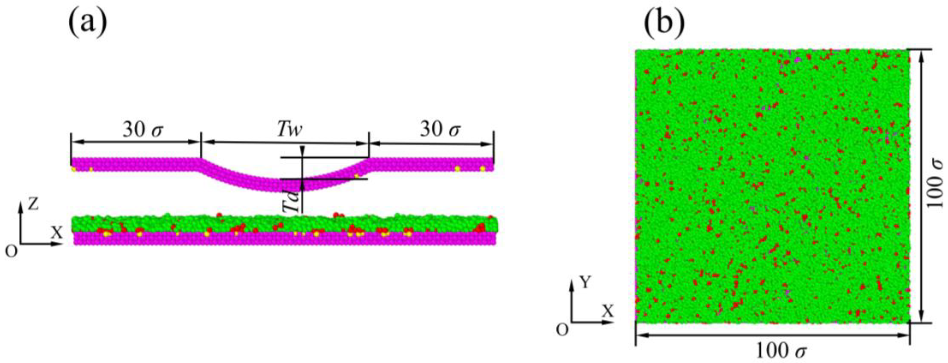
2.1. Simulation Model

The conventional lubricant PFPE was coated on the diamond-like carbon (DLC) overcoat of the disk surface due to its excellent qualities, such as corrosion protection and wear minimization [28,29]. The Fomblin lubricant with polar hydroxyl groups of PFPE had good thermal and chemical stability performance and hydrophobicity and the desirable property of lubricity [30,31]. As shown in Figure 1a, the Fomblin Zdol-type lubricant had the following copolymer structure: X CF 2 O [ ( OCF 2 CF 2 ) p ( OCF 2 ) q ] CF 2 X , where X represents the functional beads with hydroxyl groups ( CF 2 CH 2 OH ) and p / q = 9 / 13 . On the disk surface, the PFPE lubricant molecules existed in two distinct states: bonded lubricant molecules and mobile lubricant molecules. Due to the complexity of the simulation system using the all-atom model and joint atom model of lubricant molecules, this limited the number of lubricant molecules. Therefore, this study adopted a coarse-grained model to study the relevant characteristics of lubricant molecules. For complex structured compounds, coarse-grained models can more effectively simulate macromolecular polymers, simplify system force field parameters, and have the advantage of extending the simulation time.
Lubricant molecules attach to the surface of DLC through physical and chemical adsorption. Physical adsorption is a simple adsorption process that takes place between lubricant molecules and the non-functional groups of DLC, and the surface lubricant molecules have a certain degree of fluidity, while chemical adsorption takes place in the form of molecular force. However, chemical adsorption involves chemical bond action between the end groups of lubricant molecules and nitrided DLC or hydrogenated DLC. The interactions between these chemical bonds are all functional group interactions, such as vacancy bonds, carboxyl groups, hydroxyl groups, aliphatic groups, etc. Referring to the coarsening model of lubricant molecules established by Guo [32] and Li [17], Guo directly simplified DLC to a planar structure, while Li established a DLC layer with an atomic structure based on it. However, the interaction between lubricant molecules and DLC molecules was not considered in their models. In order to simulate lubricant transfer during contact and collision between the slider and the disk, after considering the interaction between DLC surface functional groups and lubricant molecules, according to the schematic of Zdol PFPE, we established an interaction between a coarse-grained bead spring model and the potential function, as shown in Figure 1b. In this model, we simplify one Zdol lubricant molecule into ten beads, consisting of eight backbone beads and two end beads. The disk surface incorporates functional groups that facilitate the chemical adsorption of lubricant molecules onto its surface.
According to references [30,33,34], three potential functions were selected owing to their ability to simulate the interactions between different beads in the molecular dynamics model, including LJ (Lennard–Jones) potential, FENE (finitely extensible nonlinear elastic) potential, and EXP (short-range attractive polar function) potential.
In the improved coarse-grained bead spring model, in order to replace the van der Waals force that acts between any two beads, the “12-6” truncate-shifted Lennard–Jones potential was employed. LJ dual potential is suitable for describing the interaction between two neutral atoms or molecules, such as the interaction between inert gas atoms. Its potential function calculation is simple and requires a small amount of computation. The expression is as shown in Equation (1):
U LJ ( R ) = 4 ε LJ [ ( σ R ) 12 ( σ R c ) 12 ( σ R ) 6 + ( σ R c ) 6 ]
where R c represents the cut-off distance, R represents the distance between two beads, ε LJ signifies the potential depth, and σ denotes the bead diameter. In this study, the molecular dynamics simulation used the LJ reduction unit; the length unit was σ and the cut-off distance was R c = 2.5 σ .
To avoid overlapping and entanglement between lubricant molecules, the interaction between neighboring atoms within lubricant molecules and DLC molecules was specifically manifested as bonding. The interaction between neighboring atoms can be described using the finitely extensible nonlinear elastic (FENE) potential. The expression is as shown in Equation (2):
U FENE ( R ) = 1 2 K R 0 2 l n [ 1 ( R R 0 ) 2 ]
where K stands for the spring constant and R 0 represents the maximum bond length. The following parameters were used in the FENE potential formula: K = 30   k B T / σ 2 and R 0 = 1.5   σ ; k B signals the Boltzmann constant and T represents the absolute temperature.
We used a short-range exponential decay function to express the interaction potential between the end groups of lubricant molecules, as well as between the end groups and DLC functional groups. Equation (3) represents the listed short-range attractive polar potential:
U EXP ( R ) = ε p exp ( R R c D )
where ε p is the strength of interaction between the lubricant molecule polar beads and functional beads of the disk and slider surface ( ε p = 4 ε LJ ). The cut-off distance is R c = 2.5   σ and the typical length of the decay is D = 0.3   σ .
The molecular dynamics model employed for the slider to make contact with the applied lubricant is shown in Figure 2. We used MATLAB programming to construct a molecular dynamics model, as shown in Figure 2. The slider surface was designed with a cylindrical asperity and was entirely coated with a DLC layer. The disk was simplified to three layers of DLC, with a lubricant layer applied on the disk surface. In the model, functional groups were randomly distributed on both the slider and the DLC (diamond-like carbon) layer of the disk. The proportion of functional groups on the slider was 5%, while the proportion of functional groups on the DLC layer of the disk was 20%. The disk surface model had a width of 100   σ and a length of 100   σ , as shown in Figure 2b. The total length of the slider was 100   σ , with a width of 50   σ . The cylindrical asperity of the slider had a width of T w = 40   σ , and the depth of the asperity was T d = 5   σ . The initial position of the slider was in the center of the disk and at a height of 20   σ from the bottom of the disk. A normal load was applied on the slider in the z direction to facilitate slider/disk contact. Finally, the periodic boundary condition was applied to the xoy plane.

2.2. Simulation Method

In order to achieve a uniform and random distribution of lubricant molecules on the DLC overcoat, the distribution was simulated in two stages [17,18,35].
In the initial stage, under the NVT (number of particles, volume, and temperature) ensemble, the xoy plane adopted periodic boundary conditions, with a free stretching boundary condition in the z-direction, and only considered the LJ potential and FENE potential energy between individual bodies. The cut-off radius was R c = 2 1 / 6   σ . There was only repulsive force between lubricant monomers. The finitely extensible nonlinear elastic potential between monomers kept them near the equilibrium position, ensuring that the lubricant molecules did not disperse due to fracture. During the simulation process, the disk remained stationary, with a time step of 0.005 τ . The temperature was kept constant at T = 1.0   ε / k B . After running the simulation for 100,000 time-steps, it was observed that the lubricant molecules exhibited a random distribution on the surface of the DLC.
In the second stage, we selected the NVE ensemble. Through the joint action of LJ, FENF, and EXP potential functions, the cut-off radius was R c = 2.5   σ . In the microcanonical ensemble state, the temperature was controlled using the Langevin hot bath method, which helped to maintain a constant ensemble temperature. After running the simulation for 400,000 time-steps, the lubricant molecules reached a stable state and were evenly distributed on the DLC surface through physical and chemical adsorption. The top view of the lubricant distribution after reaching equilibrium is shown in Figure 2b.
In the next simulation, the simulation time step was changed to 0.001   τ to simulate the process of the slider–disk contact to read and write data, and the slider was moved away from the disk after completion. When the slider contacted the disk, the lubricant on the disk surface was transferred to the slider surface due to various forces, and attached to the slider surface as it moved away from the disk. In this simulation process, the temperature was T = 1.0   ε / k B , and the disk rotated with a velocity of V = 1.0   σ / τ . The initial pressure was set to P a = 1.67   ε / σ 3 at the slider/disk interface. In addition, normal forces ( F n = 1.0   ε / σ ) were applied to the slider in the process of slider/disk contact.

3. Results and Discussion

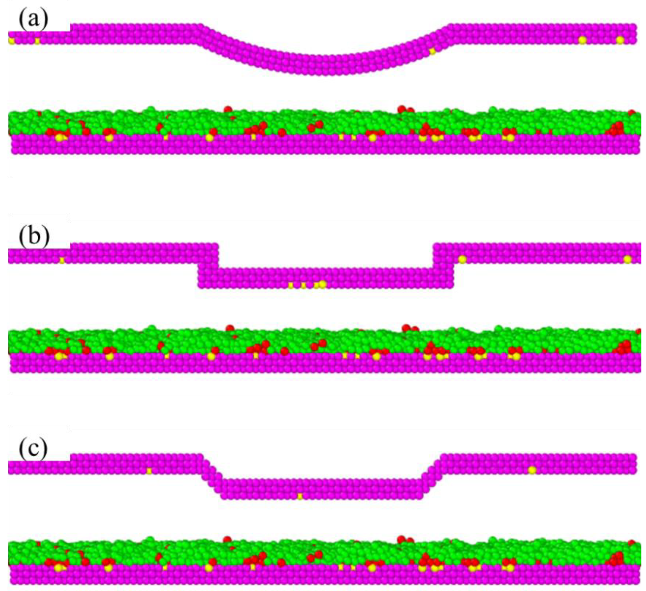
3.1. Effect of Slider Configuration

Figure 3 shows a comparison of the head–disk contact model with the different asperities of the slider. The present model studied in this paper is a cylindrical asperity slider, as shown in Figure 3a. The cuboidal asperity slider model shown in Figure 3b was obtained from [33], and the 45 ° trapezoidal asperity slider shown in Figure 3c from [36].
Figure 4 shows the relationship between the consumption of different types of lubricants and the normal force. As the normal load gradually increased, it was observed that the trend of the depletion volume resulting from the contact between cuboidal asperity and 45 ° trapezoidal asperity slider models and the disk was roughly the same. Both rapidly increased the depletion volume to 1300   σ 3 and then remained almost unchanged with further increases in normal force. As the normal force was F n 1.0   ε / σ , the lubricant depletion volume was almost invariant. However, with the increase in normal force, the depletion volume of the lubricant resulting from the contact between the cylindrical asperity slider model and the disk exhibited a slow but steady increase until it reached its maximum at a normal force of F n = 0.6   ε / σ , and then gradually tended to be constant.
This phenomenon occurred due to the cuboidal asperity and 45 ° trapezoidal asperity slider models directly hindering the fluidity of lubricant molecules when they came into contact with the disk, resulting in a large number of lubricant molecules accumulating on the left side of the magnetic head protrusion. The slider with the cylindrical asperity favored lubricant reflowing and redistribution as contact occurred. As a consequence, the accumulation of the lubricant was reduced compared with the other models. Therefore, we can conclude that the slider with the cylindrical shape was the best configuration.

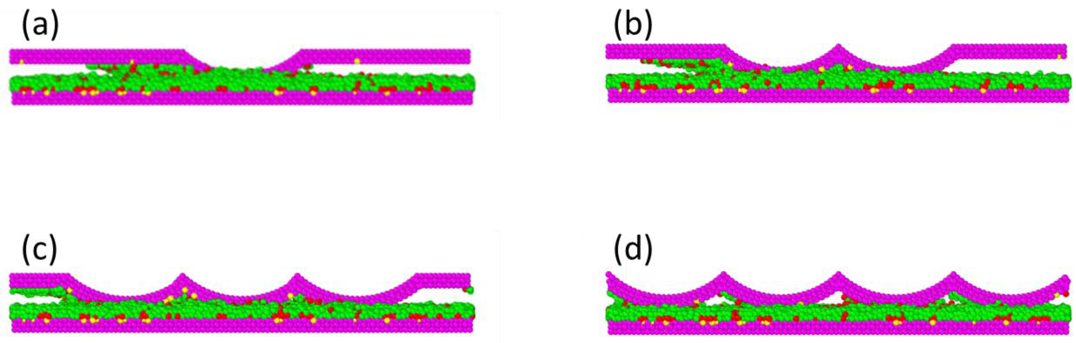
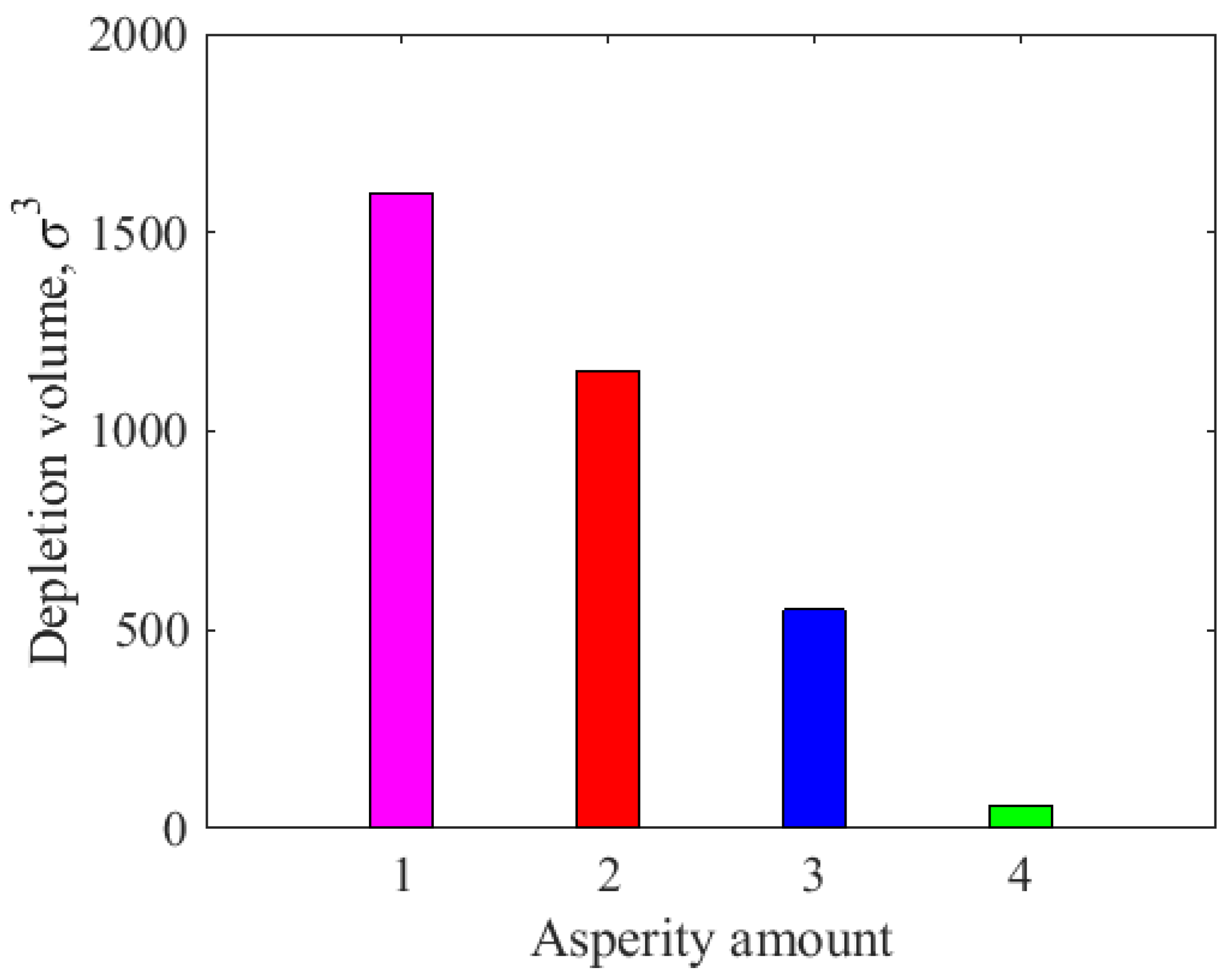
3.2. Effect of Asperity Amount

Figure 5 shows the lubricant transfer during the slider/disk contact process. As shown in Figure 5b, after the slider reached the specified height, due to the various forces (air bearing pressure, thermodynamics, and van der Waals forces) and relative motion states between the slider and disk, the lubricant gradually accumulated near the cylindrical asperity area at the left end of the slider. Because of the small distance in the interface space, over time, the accumulated lubricant molecules formed a bridge between the disk and the slider surface. When the stacking height increased to the range of atomic action on the slider surface, the accumulated lubricant molecules were transferred to the slider surface under van der Waals forces. After the slider–disk stably ran t = 250   τ , the lubricant molecules on the disk surface began to migrate, as shown in Figure 5c. After t = 350   τ , the stable operation phase ended and the slider returned to its initial position. Throughout the entire upward process, the strong molecular forces on the slider surface attracted lubricant molecules to the slider and rose together with them, as shown in Figure 5d.
According to the analysis of the lubricant loss resulting from the asperity shape of the slider, it can be concluded that the cylindrical asperity slider can effectively reduce friction loss under low load impact. Therefore, further exploration of the influence of parameter changes in cylindrical asperity sliders on friction losses will be carried out. In order to study the effect of the asperity amount on the depletion volume of the lubricant, different amounts of cylindrical asperity were formulated and are shown in Figure 6. The number of asperities on the slider varied from one to four. All of the sliders had the same dimensions, with a length of 100   σ and a width of 50   σ .
Figure 7 illustrates the changes in penetration depth when four types of sliders came into contact with the disk. When the number of cylindrical asperities was N = 1 , the penetration depth increased instantaneously with the penetration time when the slider came into contact with the disk. At this time, the penetration depth exceeded 1.5   σ , and then the change trend fluctuated greatly. When the number of cylindrical asperities was N 2 , the variation trend of the penetration depth of the slider when the slider came into contact with the disk was roughly the same. The penetration depth increased instantaneously with the penetration time and then gradually tended to be constant. During the change processes of contact depth shown in the figure, a noteworthy observation was that the increase in the number of cylindrical asperities increased the contact area of the head and disk, resulting in a decrease in the penetration depth of the slider. When the surface of the slider had multiple asperities, the contact depth between the head and disk decreased accordingly. Moreover, the penetration depth remained unchanged if the number of asperities was larger than three.
Figure 8 displays the influence of the number of different cylindrical asperities on the lubricant depletion volume. When the number of cylindrical asperities was N = 1 , the lubricant consumption resulting from the contact between the slider and the disk exceeded 1500   σ 3 . When the number of cylindrical asperities was N = 2 , the lubricant depletion volume was between 1000   σ 3   and 1500   σ 3 . When the number of cylindrical asperities was N = 3 , the depletion volume of lubricant was between 500   σ 3 and 1000   σ 3 . When the number of cylindrical asperities was N = 4 , the depletion volume of the lubricant was less than 200   σ 3 , which is negligible compared with the other three. In short, as the number of asperities on the slider increased, it became evident that the surface contact area of the head–disk increased, and the depletion volume of the lubricant in the contact state gradually decreased. Although Figure 7 shows that the penetration depth was almost the same for three asperities and four asperities, the depletion volume of the lubricant for four asperities was much lower than that for three asperities. This is because there was no more space to store the transferred lubricant for the slider with four asperities (Figure 6d). Therefore, increasing the number of slider asperities is beneficial in terms of reducing friction loss.

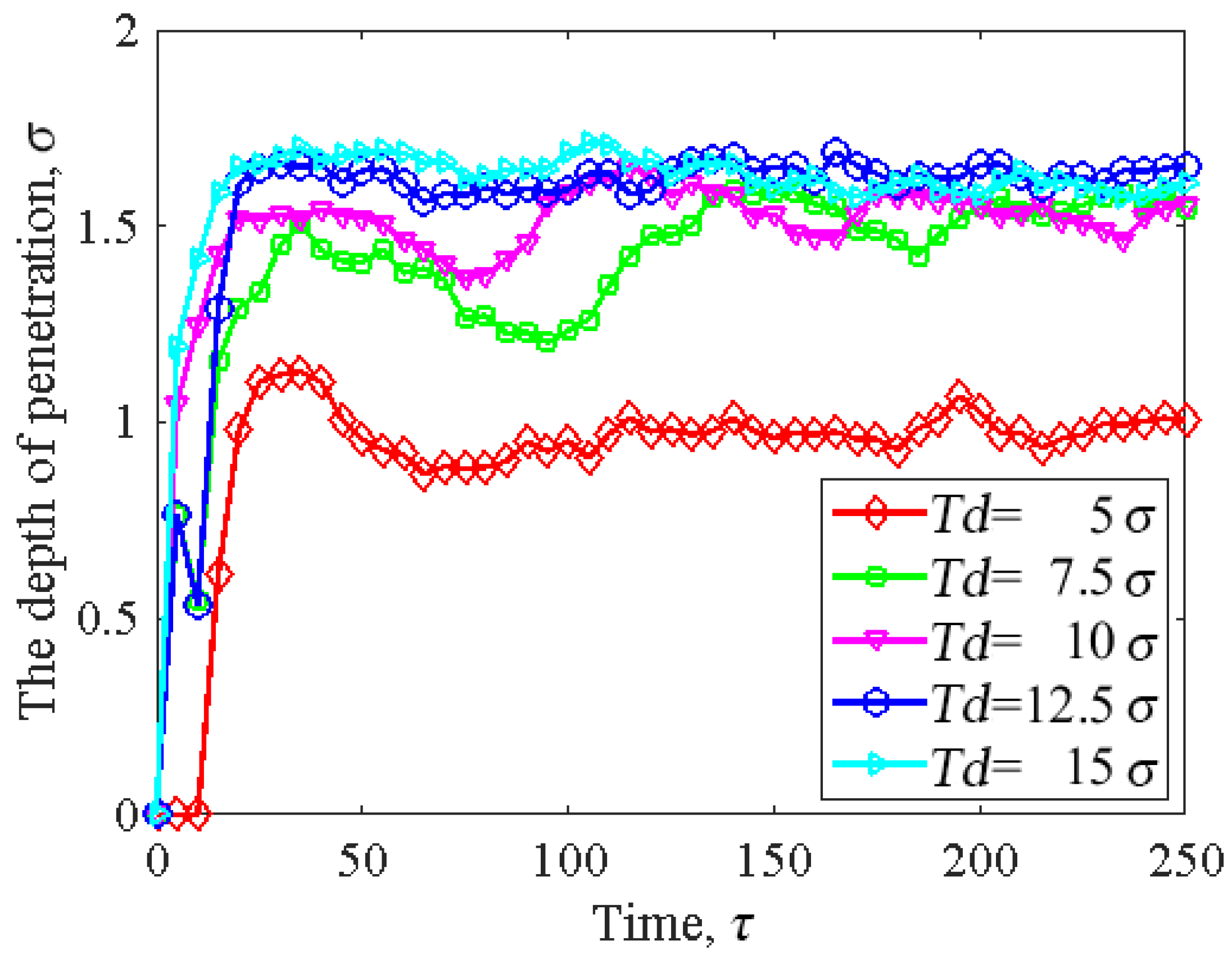
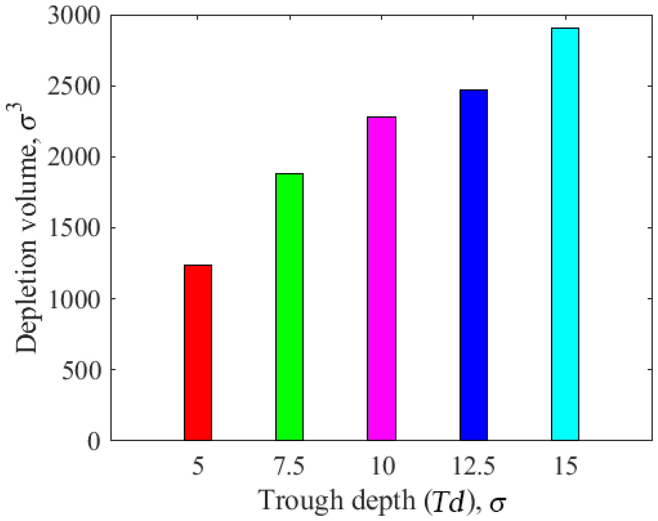
3.3. Effect of Asperity Depth

Figure 9 displays the influence of the different cylindrical asperity depths on the penetration depth of the slider. Without changing the width of the slider asperity, when the cylindrical asperity depth was T d = 5   σ , the penetration depth of the slider was the lowest. It increased instantaneously with time and then gradually tended to be stable. When the cylindrical asperity depth was T d > 5   σ , the contact depth of the head–disk increased with the increase in the asperity depth, but the overall trend of change was roughly the same. From our observations, it was evident that as the cylindrical asperity depth increased, the penetration depth gradually increased. This was mainly due to the identical asperity width ( T w = 40   σ ) of the sliders; the increase in asperity depth led to an increase in curvature. As a result, the contact area between the top of the slider and the disk decreased, which led to the penetration depth increasing.
Figure 10 illustrates the effect of the different cylindrical asperity depths on the lubricant depletion volume. When the cylindrical asperity depth was T d = 5   σ , the lubricant consumption resulting from the contact between the slider and the disk was the lowest, with a depletion volume between 1000   σ 3 and 1500   σ 3 . When the cylindrical asperity depth was T d > 5   σ , lubricant consumption increased with the increase in asperity depth; in particular, when the asperity depth was T d = 15   σ , the lubricant consumption resulting from the contact between the slider and the disk was the largest, with a depletion volume close to 3000   σ 3 . This shows that, with an increase in asperity depth, the depletion volume of the lubricant increases. As the asperity depth increased, the contact area decreased accordingly, thus explaining this situation. Thus, the change in the asperity structure of the slider has a significant impact on the lubricant loss, so reducing the asperity depth of the slider is beneficial for avoiding damage to the disk in the contact state.

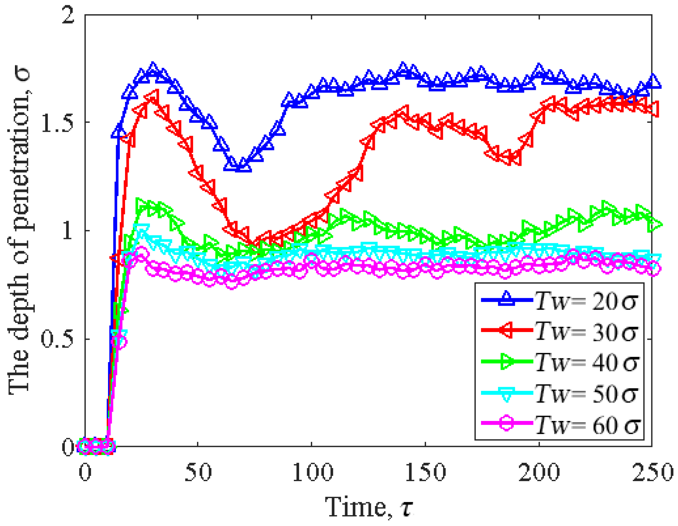
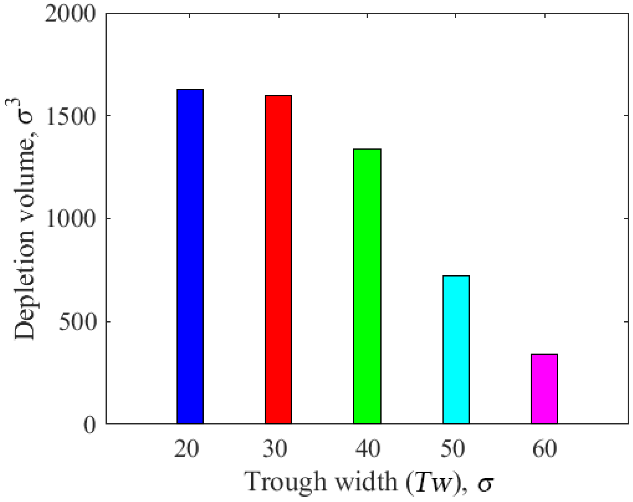
3.4. Effect of Asperity Width

Figure 11 shows the penetration depth as a function of cylindrical asperity width. Without changing the depth of the slider asperity, when the width of the cylindrical asperity was T w = 20   σ , the contact depth of the head–disk was at its maximum, and the penetration depth of the slider exceeded 1.5   σ . When the width of the cylindrical asperity was T w 40   σ , the contact depth of the head–disk instantly increased and then gradually tended to be constant, and the trends of the three were roughly the same. We can conclude that, with an increase in cylindrical asperity width, the penetration depth decreases. This was because the contact area between the slider and disk increased as the cylindrical asperity width increased, which caused the penetration depth to decrease. Furthermore, we noticed that, as the cylindrical asperity width increased, especially when it exceeded T w = 50   σ , the penetration depth became more stable.
Figure 12 displays the correlation between the cylindrical asperity width and the lubricant depletion volume. When the width of the cylindrical asperity was T w = 20   σ , the lubricant consumption resulting from the contact between the head and disk was the largest, with the depletion volume of the lubricant exceeding 1500   σ 3 . When the width of the cylindrical asperity was T w 30   σ , the lubricant consumption decreased with the increase in the asperity width; in particular, when the asperity width was T w = 60   σ , the lubricant consumption resulting from the contact between the head and disk was the lowest, and the lubricant depletion volume was less than 500   σ 3 . In brief, there was a continual decrease in the lubricant depletion volume as the cylindrical asperity width increased. This further explains the influence of the slider’s structural parameters on friction loss; in particular, when the asperity width increased to T w = 50   σ , lubricant loss significantly decreased. Therefore, the depletion volume of the lubricant greatly decreases if the slider has a cylindrical asperity with a small depth and large width, resulting in a smooth step.

4. Conclusions

The focus of this study was to analyze the impact of slider/disk contact on lubricant consumption using a molecular dynamics model. The effects of slider configuration, asperity amount, asperity depth, and asperity width on lubricant depletion were studied. This work may be helpful for the air-bearing surface design of sliders with the aim of decreasing lubricant depletion if contact occurs. The detailed conclusions of this study are summarized as follows:
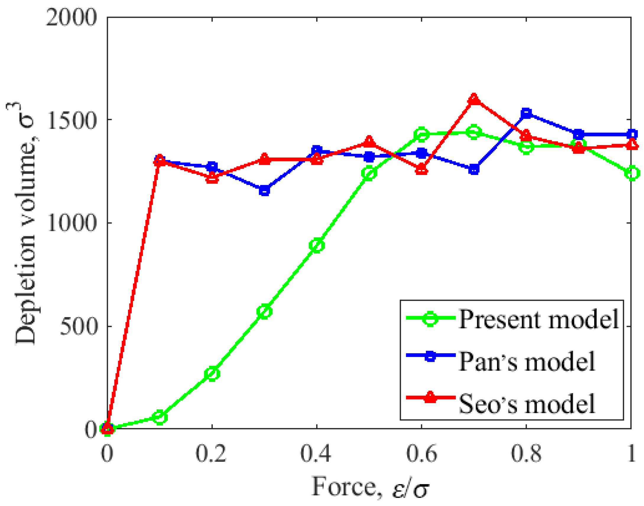
  • The slider configuration has a significant effect on the depletion volume of the lubricant. Compared with the cuboidal asperity slider and the 45 ° trapezoidal asperity slider, the cylindrical asperity slider was found to be able to reduce the depletion volume of the lubricant at small loads.
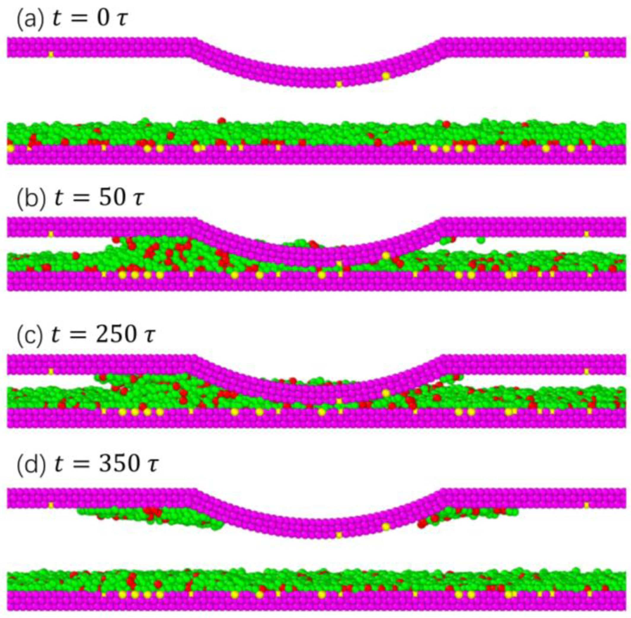
  • With an increase in the number of cylindrical asperities, the surface contact area between the head and disk increased, and the slider penetration depth decreased. This led to a reduction in the volume of lubricant depletion in the contact state. Therefore, increasing the number of slider asperities is beneficial for reducing friction loss.
  • The dimensions of cylindrical asperity, including parameters such as depth and width, play a crucial role in determining the penetration depth and lubricant depletion. As the cylindrical asperity depth increased, the penetration depth gradually increased. And with the increase in cylindrical asperity width, the penetration depth decreased. In addition, the depletion volume of lubricant decreased with the decrease in asperity depth and also decreased with the increase in asperity width.

Author Contributions

Y.C.: Conceptualization, Data curation, Formal analysis, Investigation, Methodology, Writing-original draft preparation, Writing-review and editing, Visualization. D.Z.: Conceptualization, Software, Formal analysis, Data curation, Investigation, Methodology, Validation, Resources. Z.T.: Funding acquisition, Supervision, Writing-review and editing. All authors have read and agreed to the published version of the manuscript.

Funding

This research was funded by the National Science Foundation of China (52165022), the Science and Technology Project of Guizhou Province ([2020]1Y415), and the Science and Technology Innovation Team Project in Guizhou Province ([2020]5020).

Data Availability Statement

The data that support the findings of this study are available within the article.

Conflicts of Interest

The authors declare that they have no known competing financial interest or personal relationships that could have appeared to influence the work reported in this paper.

References

  1. Marchon, B.; Pitchford, T.; Hsia, Y.T.; Gangopadhyay, S. The head-disk interface roadmap to an areal density of Tbit/in2. Adv. Tribol. 2013, 2013, 521086. [Google Scholar] [CrossRef]
  2. Song, J.; Yeo, C.D. Finite element analysis simulations of thermomechanical head-disk interface contact in thermal flying-height control slider design. Tribol. Int. 2016, 98, 299–305. [Google Scholar] [CrossRef]
  3. Canchi, S.V.; Bogy, D.B. Experiments on slider lubricant interactions and lubricant transfer using TFC sliders. Microsyst. Technol. 2012, 18, 1517–1523. [Google Scholar] [CrossRef]
  4. Itoh, J.; Sasaki, Y.; Higashi, K.; Takami, H.; Shikanai, T. An experimental investigation for continuous contact recording technology. IEEE Trans. Magn. 2001, 37, 1806–1808. [Google Scholar] [CrossRef]
  5. Chen, Y.K.; Peng, J.P.; Bogy, D.B. Experimental and simulation study of thermal protrusion-induced head-disk contact instabilities in hard disk drives. IEEE Trans. Magn. 2014, 50, 1–5. [Google Scholar] [CrossRef]
  6. Li, N.; Meng, Y.; Bogy, D.B. Effects of PFPE lubricant properties on the critical clearance and rate of the lubricant transfer from disk surface to slider. Tribol. Lett. 2011, 43, 275–286. [Google Scholar] [CrossRef]
  7. Zeng, Q.; Yang, C.H.; Ka, S.; Cha, E. An experimental and simulation study of touchdown dynamics. IEEE Trans. Magn. 2011, 47, 3433–3436. [Google Scholar] [CrossRef]
  8. Sarabi, S.; Bogy, D.B. Effect of viscoelasticity on lubricant behavior under heat-assisted magnetic recording conditions. Tribol. Lett. 2018, 66, 33. [Google Scholar] [CrossRef]
  9. Li, N.; Meng, Y.; Bogy, D.B. Experimental study of the slider-lube/disk contact state and its effect on head-disk interface stability. IEEE Trans. Magn. 2012, 48, 2385–2391. [Google Scholar] [CrossRef]
  10. Chowdhury, S.; Vakis, A.I.; Polycarpou, A.A. Optimization of molecularly thin lubricant to improve bearing capacity at the head-disk interface. Microsyst. Technol. 2014, 21, 1501–1511. [Google Scholar] [CrossRef]
  11. Tani, H.; Iwasaki, K.; Maruyama, Y.; Ota, I.; Tagawa, N. Lubricant pickup of ultra-thin PFPE lubricants with different backbone structures. IEEE Trans. Magn. 2011, 47, 1837–1841. [Google Scholar] [CrossRef]
  12. Waltman, R.J.; Deng, H.; Wang, G.J.; Zhu, H.; Tyndall, G.W. The effect of PFPE film thickness and molecular polarity on the pick-up of lubricant by a low-flying slider. Tribol. Lett. 2010, 39, 211–219. [Google Scholar] [CrossRef]
  13. Ma, X.; Tang, H.; Stirniman, M.; Gui, J. The effect of slider on lubricant loss and redistribution. IEEE Trans. Magn. 2002, 38, 2144–2146. [Google Scholar]
  14. Ma, Y.S.; Chen, X.Y.; Zhao, J.M.; Yu, S.K.; Liu, B.; Seet, H.L.; Ng, K.K.; Hu, J.F.; Shi, J.Z. Experimental study of lubricant depletion in heat assisted magnetic recording. IEEE Trans. Magn. 2012, 48, 1813–1818. [Google Scholar] [CrossRef]
  15. Lin, W.U. Modelling and simulation of the lubricant depletion process induced by laser heating in heat-assisted magnetic recording system. Nanotechnology 2007, 18, 215702. [Google Scholar]
  16. Norio, T.; Hideki, A.; Hiroshi, T. Study on lubricant depletion induced by laser heating in thermally assisted magnetic recording systems: Effect of lubricant thickness and bonding ratio. Tribol. Lett. 2010, 37, 411–418. [Google Scholar]
  17. Li, Y.; Wong, C.H.; Li, B.; Yu, S.; Hua, W.; Zhou, W. Lubricant evolution and depletion under laser heating: A molecular dynamics study. Soft Matter 2012, 8, 5649–5657. [Google Scholar] [CrossRef]
  18. Wong, C.H.; Li, B.; Yu, S.K.; Hua, W.; Zhou, W.D. Molecular dynamics simulation of lubricant redistribution and transfer at near-contact head-disk interface. Tribol. Lett. 2011, 43, 89–99. [Google Scholar] [CrossRef]
  19. Li, B.; Wong, C.H.; Chen, Q.B. Evolution of Diffusion-Related Degradation of Polymeric Lubricant under Laser Heating: A Molecular Dynamics Study. IEEE Trans. Magn. 2014, 50, 1–9. [Google Scholar] [CrossRef]
  20. Li, B.; Wong, C.H. Molecular Dynamics Simulation of Thermal-Induced Local Heating and Depletion of Ultrathin Perfluoropolyether Lubricant under Moving Laser Heating. Tribol. Lett. 2014, 55, 303. [Google Scholar] [CrossRef]
  21. Seo, Y.W.; Rosenkranz, A.; Talke, F.E. Molecular Dynamics Study of Lubricant Depletion by Pulsed Laser Heating. Appl. Surf. Sci. 2018, 440, 73–83. [Google Scholar] [CrossRef]
  22. Xu, Q.; Li, X.; Zhang, J.; Hu, Y.; Wang, H.; Ma, T. Suppressing nanoscale wear by graphene/graphene interfacial contact architecture: A molecular dynamics study. ACS Appl. Mater. Interfaces 2017, 9, 40959–40968. [Google Scholar] [CrossRef] [PubMed]
  23. Dai, L.; Sorkin, V.; Sha, Z.D.; Pei, Q.X.; Branicio, P.S.; Zhang, Y.W. Molecular dynamics simulations on the frictional behavior of a perfluoropolyether film sandwiched between diamond-like-carbon coatings. Langmuir 2014, 30, 1573–1579. [Google Scholar] [CrossRef] [PubMed]
  24. Chung, P.S.; Park, H. Thermal Diffusion Phenomena of the Functional Polymer Lubricants for the Heat-Assisted Magnetic Recording. IEEE Trans. Magn. 2019, 55, 3300604 . [Google Scholar] [CrossRef]
  25. Liu, D.; Li, H.; Huo, L.; Wang, K.; Sun, K.; Wei, J.; Chen, F. Molecular dynamics simulation of the lubricant conformation changes and energy transfer of the confined thin lubricant film. Chem. Eng. Sci. 2023, 270, 118541. [Google Scholar] [CrossRef]
  26. Song, J.; Talukder, S.; Rahman, S.M.; Jung, Y.; Yeo, C.-D. Comparison study on surface and thermo-chemical properties of PFPE lubricants on DLC film through MD simulations. Tribol. Int. 2021, 156, 106835. [Google Scholar] [CrossRef]
  27. Tang, Z.; Zhou, D.; Jia, T.; Zhang, X.; Pan, D. Effect of Air Bearing Pressure and Slider/disk Contact on Lubricant Depletion Using Molecular Dynamics Simulation. IEEE Trans. Magn. 2020, 56, 6702804. [Google Scholar] [CrossRef]
  28. Waltman, R.J.; Pocker, D.J.; Tyndall, G.W. Studies on the interactions between ZDOL perfluoropolyether lubricant and the carbon overcoat of rigid magnetic media. Tribol. Lett. 1998, 4, 267–275. [Google Scholar] [CrossRef]
  29. Zhao, Z.; Bhushan, B.; Kajdas, C. Tribological performance of PFPE and X-1P lubricants at head-disk interface. Part II. Mechanisms. Tribol. Lett. 1999, 6, 141–148. [Google Scholar] [CrossRef]
  30. Li, B.; Wong, C.H. Lubricant depletion due to moving laser heating: A molecular dynamics simulation study. Tribol. Int. 2014, 80, 41–48. [Google Scholar] [CrossRef]
  31. Choi, H.J.; Guo, Q.; Chung, P.S.; Jhon, M.S. Molecular rheology of perfluoropolyether lubricant via nonequilibrium molecular dynamics simulation. IEEE Trans. Magn. 2006, 99, 903–905. [Google Scholar] [CrossRef]
  32. Guo, Q.; Izumisawa, S.; Phillips, D.M.; Jhon, M.S. Surface Morphology and Molecular Conformation for Ultrathin Lubricant Films with Functional End Groups. J. Appl. Phys. 2003, 93, 8707. [Google Scholar] [CrossRef]
  33. Pan, D.; Ovcharenko, A.; Tangaraj, R.; Yang, M.; Talke, F.E. Investigation of lubricant transfer between slider and disk using molecular dynamics simulation. Tribol. Lett. 2014, 53, 373–381. [Google Scholar] [CrossRef]
  34. Guo, Q.; Li, L.; Hsia, Y.T.; Jhon, M. A Spreading Study of Lubricant Films via Optical Surface Analyzer and Molecular Dynamics. IEEE Trans. Magn. 2006, 42, 2528–2530. [Google Scholar] [CrossRef]
  35. Pan, D.; Ovcharenko, A.; Peng, J.P.; Jiang, H. Effect of lubricant fragments on lubricant transfer: A molecular dynamics simulation. IEEE Trans. Magn. 2014, 50, 3302005. [Google Scholar] [CrossRef]
  36. Seo, Y.W.; Pan, D.Z.; Ovcharenko, A.; Yang, M.; Talke, F.E. Molecular dynamics simulation of lubricant transfer at the head-disk interface. IEEE Trans. Magn. 2014, 50, 3302904. [Google Scholar] [CrossRef]
Figure 1. The simplicity of the PFPE Zdol-type lubricant (a); the potential interactions between different beads (b).
Lubricants 12 00017 g001
Figure 2. Schematic of the head–disk model with a cylindrical asperity (a); the top view of the lubricant distribution on the DLC overcoat (b).
Lubricants 12 00017 g002
Figure 3. The head–disk contact model with different slider configurations: (a) a cylindrical asperity; (b) cuboidal asperity [33]; (c) 45 ° trapezoidal asperity [36]. T d = 5   σ , T w = 40   σ   , V = 1.0   σ / τ , and   P = 1   P a .
Lubricants 12 00017 g003
Figure 4. The head–disk contact with different slider configurations: the functional relationship between the depletion volume of lubricant and normal force [33,36].
Lubricants 12 00017 g004
Figure 5. The lubricant transfer during the slider/disk contact process. T d = 5   σ , T w = 25   σ , V = 1.0   σ / τ ,   P = 1   P a , and F n = 0.5   ε / σ .
Lubricants 12 00017 g005
Figure 6. Contact model with different amounts of cylindrical asperities: (a) single cylindrical asperity; (b) two cylindrical asperities; (c) three cylindrical asperities; (d) four cylindrical asperities. T d = 5   σ , T w = 25   σ , V = 1.0   σ / τ ,   P = 1   P a , and F n = 0.5   ε / σ .
Lubricants 12 00017 g006
Figure 7. The penetration depth as a function of asperity amount.
Lubricants 12 00017 g007
Figure 8. The influence of the number of different cylindrical asperities on the depletion volume of lubricant.
Lubricants 12 00017 g008
Figure 9. The influence of the cylindrical asperity depth on the penetration depth of the slider: T w = 40   σ   , V = 1.0   σ / τ ,   P = 1   P a , and F n = 0.5   ε / σ .
Lubricants 12 00017 g009
Figure 10. The effect of the cylindrical asperity depth on the depletion volume of lubricant.
Lubricants 12 00017 g010
Figure 11. The correlation between asperity width and the depletion volume of lubricant: T d = 5   σ   , V = 1.0   σ / τ ,   P = 1   P a , and F n = 0.5   ε / σ .
Lubricants 12 00017 g011
Figure 12. The correlation between asperity width and the depletion volume of lubricant.
Lubricants 12 00017 g012
Disclaimer/Publisher’s Note: The statements, opinions and data contained in all publications are solely those of the individual author(s) and contributor(s) and not of MDPI and/or the editor(s). MDPI and/or the editor(s) disclaim responsibility for any injury to people or property resulting from any ideas, methods, instructions or products referred to in the content.

