Article

Multi-Field Coupling Numerical Analysis and Experimental Validation of Surface-Textured Metal Seals in Roller Cone Bits

1
College of Mechanical Engineering, Zhejiang University of Technology, Hangzhou 310023, China
2
Engineering Research Center of Process Equipment and Remanufacturing, Ministry of Education, Hangzhou 310023, China
*
Authors to whom correspondence should be addressed.
Lubricants 2024, 12(1), 15; https://doi.org/10.3390/lubricants12010015
Submission received: 26 October 2023 / Revised: 27 December 2023 / Accepted: 4 January 2024 / Published: 6 January 2024
(This article belongs to the Special Issue Tribology of Textured Surfaces)

Abstract

:
Metal seals play a crucial role in ensuring the dependable functioning of the bearing system in roller cone bits. Due to the intricate nature of downhole conditions, the microstructure design of sealing end faces, specifically the surface texture, is rarely used in metal seals. This study focuses on examining the applicability of surface texture technology in metal seals for cone bits to enhance the lubrication characteristics and friction and wear properties of liquid film between end faces. A multi-field coupling model of surface-textured metal seals was established and experimentally verified. The liquid film carrying the capacity and sealing performance of five different shapes of surface-textured end faces (circle, ellipse I (horizontal), ellipse II (vertical), triangle, and chevron) were investigated under varying rotational speeds and environmental pressures. The influences of texture parameters, including depth and area ratio, on the lubrication characteristics and friction reduction effects of surface-textured metal seals were investigated, and the microscopic wear morphology characteristics of the sealing end faces were analyzed. The results show that surface textures can effectively improve the liquid film state and comprehensive performance of metal seals. Specifically, triangle textures significantly enhance the hydrodynamic pressure effect and weaken the abrasive wear and adhesive wear of the end faces. However, when the environmental pressure is p ≥ 30 MPa, the surface textures gradually lose the advantages of dynamic lubrication but can still reduce friction. The proper texture depth and area ratio can achieve zero leakage (obtained theoretically) and minimal friction in metal seals.

1. Introduction

Roller cone bits are essential rock-breaking drilling tools in the field of geological exploration engineering [1,2]. Metal seals are extensively employed as vital components in the bearing sealing system of these bits, owing to their simple structure, compact size, and ability to withstand high pressure [3]. The performance and longevity of roller cone bits are directly influenced by the effectiveness of these metal seals [4]. However, when subjected to varying downhole temperature and pressure conditions, as well as external mudflow [5,6], the metal seals are susceptible to a range of issues, including an inadequate opening force between end faces, an excessive temperature rise, and severe wear [7,8]. Previous studies have shown that the utilization of surface texture technology can enhance the load-bearing capacity of the liquid film on end faces and the anti-wear performance of conventional mechanical seals [9,10,11]. Nevertheless, the feasibility and effectiveness of surface texture technology to enhance the performance of metal seals in downhole conditions remain uncertain. Therefore, clarifying the liquid film state and comprehensive performance of surface-textured metal seals is necessary for the applicability study of texture in multi-physics drilling environments.
In recent years, some researchers have conducted numerical simulations and macrostructural optimization of metal seals in roller cone bits. Xiong and Salant [12,13] and Ma et al. [14,15] established steady-state and dynamic multi-field coupling numerical models for first- and second-generation metal seals, respectively, and analyzed the changes in liquid film characteristics, temperature field distribution, and leakage rate with operating parameters. Although few literatures have studied surface-textured metal seals, the mature research methods and results of surface texture in bearings and mechanical seals can serve as valuable insights for investigating the multi-field coupling of surface-textured metal seals. Etsion et al. [16,17] developed an analytical model for micropore-textured mechanical seals, demonstrating that optimally textured seals can significantly reduce friction and heat generation. Brunetiere and Tournerie [18] and Yang et al. [19] considered the cavitation phenomenon, asperity contact, and viscosity–temperature effect of mechanical seals and numerically studied the differences in the liquid film bearing capacity and frictional state of end faces with different texture parameters or shapes. The findings revealed a strong correlation between the leakage of sealing end faces and the density of surface texture. Moreover, the study demonstrated that triangle textures are more effective for enhancing the hydrodynamic performance of the mechanical seals. Qiu and Khonsari [20] and Dingui et al. [21] conducted friction and performance tests on laser-surface-textured rings or mechanical seals, respectively. They found that the size and depth of dimples have a significant impact on the load-carrying capacity and friction coefficient, and the interaction between roughness and surface textures on the behavior of mechanical seals cannot be ignored. However, there is a scarcity of studies that investigate the multi-field coupling simulation and experimental research of surface-textured metal seals. Consequently, the applicability of surface textured technology in the metal seals in cone bits needs to be solved urgently.
This study aimed to enhance the lubrication and sealing performance of metal seals in roller cone bits by applying surface texture technology. A multi-field coupling numerical model of surface-textured metal seals was established to reveal the mechanism of textures on the friction reduction and lubrication enhancement of end faces. The influences of key operating parameters and surface texture parameters on the liquid film characteristics and sealing performance of metal seals were analyzed. To validate the accuracy of the numerical results, a comprehensive test bench of surface-textured metal seals was constructed, and the interface temperature rise and wear morphology on the end faces of metal seals were tested and compared. The results offer novel insights into the application of surface textures with varying shapes and parameters on metal seals in intricate downhole environments.

2. Numerical Model

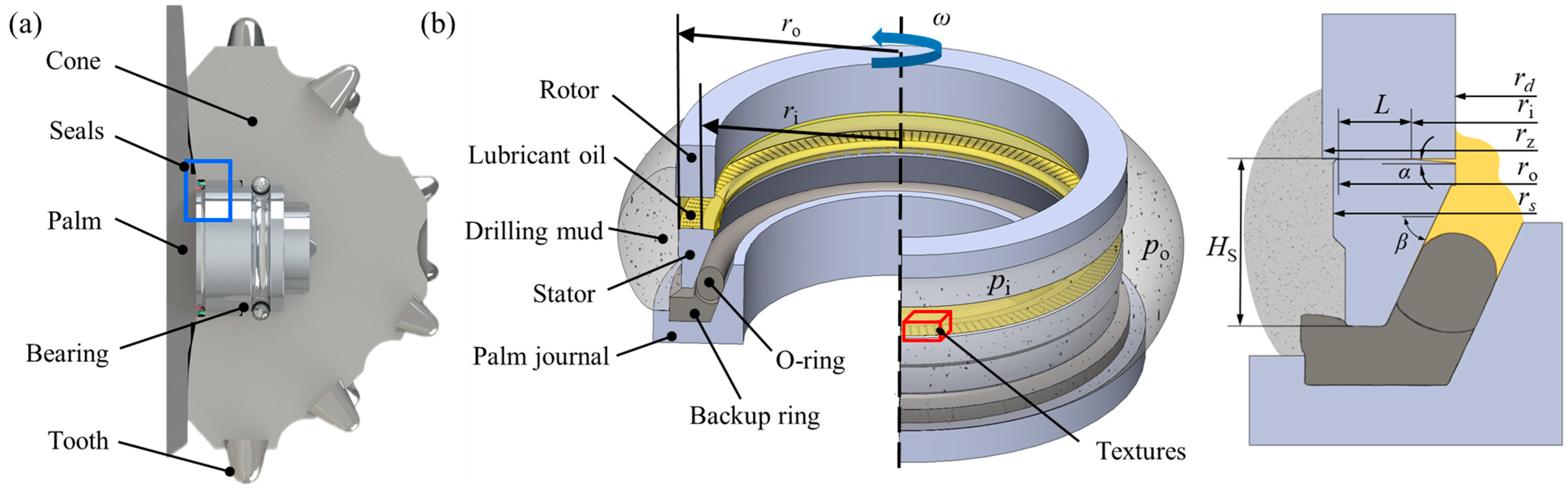
2.1. Geometric Model

The metal seals specifically developed for roller cone bits were adopted as the research objective, as shown in Figure 1. Metal seals, categorized as convergent cone seals, consist primarily of metal sealing rings (rotor and stator) and auxiliary rubber seals (O-ring and backup ring) [22,23]. The rotor is installed within the cone and rotates with the cone during drilling. The stator is elastically supported by the O-ring and backup ring, which are fixed using the palm journal, ensuring a close fit between the end faces of the stator and rotor. The lubricant oil and drilling mud serve as the media on the inner and outer diameter sides of metal seals, respectively [12,24]. The cavities on both sides of the metal seals maintain a specific pressure difference (Δp) to prevent drilling mud from invading the bearing system. The structural and operating parameters of the metal seals are shown in Table 1.
The sealing end face of the stator can be divided into three zones: the wedge angle zone (radial range of rd~ri) on the inner diameter side, the sealing zone (radial range of ri~ro) in the middle, and the chamfering zone (radial range of ro~rs) on the outer diameter side. Within the sealing zone of the stator, five typical micro-texture shapes, namely, circle, ellipse I (horizontal), ellipse II (vertical), triangle, and chevron [25,26], are adopted, as shown in Figure 2. The micro-textures with the same size are uniformly distributed in the sealing zone in a circular array of T columns. Each column comprises Nt micro-textures along the radius with a depth, hp, and an area ratio, Sp. The texture parameters are shown in Table 2.

2.2. Multi-Field Coupling Model

2.2.1. Fluid Lubrication Analysis

The following assumptions are made in the fluid lubrication analysis: the fluid flow on the sealing end faces is laminar, the influence of inertial force and volume force can be ignored, the pressure gradient along the thickness direction of the liquid film is unaffected, and the sealing medium is a Newtonian fluid.
Considering the influence of roughness on the sealing performance, the average flow model [27,28] is introduced, and the Reynolds equation can be expressed as
1 r θ ϕ θ h 3 12 μ p θ + r ϕ r r h 3 12 μ p r = ω 2 r ( ϕ c h θ + σ ϕ s θ )
where r and θ are the radial coordinate and the circumferential coordinate, respectively, μ is the viscosity of the sealing medium, p is the liquid film pressure, ω is the rotational angular velocity of the rotor, and h is the liquid film thickness, which can be described respectively for the textured zone and nontextured zone [29,30] as follows:
h = h 0 + h p + δ Textured   zone h 0 + δ Non-textured   zone
where h0 is the sealing gap, hp is the texture depth and δ is the deformation of the sealing end faces.
ϕr and ϕθ are pressure flow factors, expressed as
ϕ r = ϕ θ = 1 C e γ H
where H is the film thickness ratio (H = h/σ), σ is the comprehensive root mean square roughness of the end face, and C and γ are constants.
ϕs is the shear flow factor, expressed as
ϕ s = ( σ 1 2 σ 2 2 σ 2 ) Φ s
where σ1 and σ2 are the standard deviations of the surface roughness of the rotor and stator, respectively, and Φs can be calculated as [28]
  Φ s = 1.899 H α 1 e α 2 H + α 3 H 2 ( H 5 ) Φ s = 1.126 e α 4 H     ( H > 5 )
where α1, α2, α3, and α4 are constants.
ϕc is the contact factor, which can be expressed as
ϕ c = 1 2 [ 1 + erf ( h 2 σ ) ]
Based on the Jakobsson–Floberg–Olsson (JFO) cavitation boundary condition [31,32], the liquid film density ratio (Φ = ρ/ρc) is introduced to consider the cavitation effect, where ρ is the density of the sealing medium and ρc is the density of the sealing medium at the cavitation zone. Equation (1) can be written as
1 r θ ϕ θ h 3 p θ + r ϕ r r h 3 p r = 6 μ ω r ( ϕ c ( h Φ ) θ + σ ϕ s θ ) Φ = 1 , p > p c C o m p l e t e   l i q u i d   f i l m   z o n e 0 < Φ < 1 , p < p c     C a v i t a t i o n   z o n e
where pc is the cavitation pressure.
In this study, the Reynolds Equation (7) is discretized using the finite difference method. The computational domain in the polar coordinate system is partitioned into structured control volume grids, and nodes denoted as (i, j), (i − 1, j), (i, j − 1) are generated at the junction of each control volume grid, as shown in Figure 3a. The nodes along the r direction and θ direction are referred to as radial nodes and circumferential nodes, respectively. Each column on the sealing end faces is divided into Nr nodes along the radial direction and divided into the same unit node length along the circumferential direction to obtain fully structured grids [33,34]. According to the number of textures Nt, each column can be regarded as a composition of Nt evenly distributed units along the radial direction. Given the initial film thickness h0 and texture shape criterion rp, the center of the unit is taken as the origin to determine whether the position of each node in each unit is within the texture boundary. Thus, the initial grid nodes of the textured column are generated. Furthermore, the grid refinement and independence verification of the computational domain are performed to enhance the texture boundary treatment. The numerical models of each texture column with the number of radial nodes Nr ranging from 50 to 450 are selected for independence verification. The results show that the error of the numerical results is within 0.5% when the number of radial nodes Nr reaches 300. Therefore, this study adopts the numerical model with 300 radial nodes to conduct the simulation, considering the calculation time and accuracy, as shown in Figure 3b.
After discretization, the Reynolds Equation (7) can be written as
A p i + 1 , j + B p i 1 , j + C p i , j + 1 + D p i , j 1 E p i , j F Φ i , j + G Φ i 1 , j H = 0
where A, B, C, D, E, and F are coefficients, expressed as
A = 1 r i , j Δ θ 2 k i + 1 2 , j = 1 r i , j Δ θ 2 ( ϕ θ h 3 ) i + 1 2 , j ,   B = 1 r i , j Δ θ 2 k i 1 2 , j = 1 r i , j Δ θ 2 ( ϕ θ h 3 ) i 1 2 , j ,   C = 1 r i , j Δ θ 2 k i , j + 1 2 = 1 Δ r 2 ( ϕ r r h 3 ) i , j + 1 2 ,   D = 1 r i , j Δ θ 2 k i , j 1 2 = 1 Δ r 2 ( ϕ r r h 3 ) i , j 1 2 ,   E = A + B + C + D ,   F = 6 μ ω r Δ θ ( ϕ c h ) i , j ,   G = 6 μ ω r Δ θ ( ϕ c h ) i 1 , j ,   H = 3 μ ω r σ ( ϕ s ) i + 1 , j ( ϕ s ) i 1 , j Δ θ
where k i + 1 2 , j ,   k i 1 2 , j , k i , j + 1 2 ,   and   k i , j 1 2 are node diffusion coefficients.
Due to the significant increase in the film thickness gradient near the texture boundary, the node diffusion coefficients are introduced and discretized in an arithmetic average method to improve the calculation accuracy [35].
The liquid film thicknesses (h) of diffusion coefficients are discretized using an arithmetic average method, given as
h i 1 / 2 , j = ( h i , j + h i 1 , j ) / 2 ,   h i + 1 / 2 , j = ( h i , j + h i + 1 , j ) / 2 h i , j 1 / 2 = ( h i , j + h i , j 1 ) / 2 ,   h i , j + 1 / 2 = ( h i , j + h i , j + 1 ) / 2
Furthermore, the liquid pressure (p) and the liquid film density ratio (Φ) can be expressed as
p i , j = A p i + 1 , j + B p i 1 , j + C p i , j + 1 + D p i , j 1 F Φ i , j + G Φ i 1 , j H E Φ i , j = A p i + 1 , j + B p i 1 , j + C p i , j + 1 + D p i , j 1 E p i , j + G Φ i 1 , j H F

2.2.2. Mechanical Analysis

When the metal seals of the roller cone bit work stably, the opening force (Fopen) and closing force (Fclose) between the end faces of the stator and rotor are in balance, and a stable liquid film forms in the sealing gap. Since the metal seals are contact seals, the opening force (Fopen) comprises the above bearing force of liquid film (Fp) and the contact force of the asperities (Fc). The contact force (Fc) can be characterized using the plastic contact model [36,37] as follows:
F c = 0 2 π r i r o p c r d r d θ = H 2 π r i r o h 1 σ 2 π e ( z 2 / 2 σ 2 ) d z r d r
where pc is the contact pressure, H is the flow stress (yield stress or compressive strength) of the softer face material, and z is the axial coordinate.
The closing force (Fclose) is produced through the support of the O-ring and backup ring to the floating stator, as well as the influence of the inner and outer pressure. It can be determined by integrating the static contact pressure (psc) on the end faces of metal seals. Considering the significant nonlinearity and complex structural arrangement of the rubber O-ring and backup ring, a two-dimensional axisymmetric finite element numerical model of metal seals is established via ANSYS 15.0 software to conduct the mechanical analysis, as shown in Figure 4.
Both the metal rotor and stator are made of alloy steel 20CrNiMo with the elastic modulus E = 2.03 × 10⁵ MPa and Poisson’s ratio ν = 0.3 [38]. The rubber O-ring and backup ring use the typical hyperelastic material fluororubbers (FKM). The two-parameter Mooney–Rivlin hyperelastic model is adopted to describe the strain energy function of the rubber, given as [39,40]
W = C 10 ( I ¯ 1 3 ) + C 01 ( I ¯ 2 3 )
where I ¯ 1 and I ¯ 2 are the first and second invariants of stress tensors, respectively, and C10 and C01 are the parameters, with C10 = 1.444 and C01 = 0.0165 for the O-ring and C10 = 1.833 and C01 = −0.003 for the backup ring.
The PLANE182 axisymmetric solid element is adopted in the analysis, and the CONTA172 element and TARGE169 element are adopted for low hardness contact surfaces and high hardness target surfaces, respectively. The finite element analysis procedure consists of the following steps (as shown in Figure 4): Step 1 entails pre-compressing the metal seals. The axial displacement constraint (Uy = Y) is applied to the journal, and the radial and axial fixed constraint boundary conditions (Uy = 0, UX = 0) are applied to the outer diameter side and back of the rotor, respectively. Step 2 entails applying the lubricant oil pressure and mud pressure on the inner and outer sides of the metal seals. After the numerical solution, the static contact pressure (psc), close force (Fclose), and initial deformation of the end faces on the metal seals can be obtained under environmental pressure.

2.2.3. Thermal Analysis

The following assumptions are made in the thermal analysis: the thermal conductivities of the sealing rings are constant, and the heat losses carried away by the leakage medium and caused by radiation are unaffected.
The heat generation rate (q) between the end faces of metal seals can be determined via the viscous shear heat of liquid film and the frictional heat of asperity contact, given as [41]
q = 0 2 π r i r o μ r 2 ω 2 h r d r d θ + 0 2 π r i r o f 0 p c r ω r d r d θ
where ω is the rotational angular velocity, and f0 is the dry friction coefficient [42,43].
The rotor is convectively heated with the lubricant oil on the inner side, and the contact zones between the top and outer sides of the rotor and the cone are regarded as constant temperature boundaries. Similarly, the stator is convectively heated with the drilling mud on the outer side and the lubricant oil on the inner side, and the bottom and lower part of the inner side of the stator are regarded as adiabatic boundaries.
The heat conduction equation of the sealing rings is
r k T r + z k T z = 0
where T is the temperature of the sealing ring, and k is the thermal conductivity of the ring material.
The boundary conditions of heat flux and convective heat transfer are
k T n c S 1 q = 0
k T n c S 2 + h c ( T T 0 ) = 0
where S1 and S2 are the corresponding surfaces, hc is the convective heat transfer coefficient, T0 is the environmental temperature, and nc is the exterior normal direction.

2.2.4. Deformation Analysis

The liquid film thickness of the metal seals is directly related to the deformations of the end faces. The total deformation of the sealing end faces (δ) is composed of mechanical deformation (δm) and thermal deformation (δt). The microscopic deformation of the stator and rotor can be solved using the influence factor method [41].
The total deformation of a radial node i on end faces is
δ i = D I i + D R i + D S i
where DIi is the initial deformation at radial node i, and DRi and DSi are the deformations of the rotor and stator at radial node i, respectively, expressed as
D R i = j = 1 n M R i j F j + j = 1 n T R i j q j
D S i = j = 1 n M S i j F j + j = 1 n T S i j q j
where Fj is the force acting on the node j, qj is the heat generation rate, M R i j and M S i j are the influence factor matrices of the mechanical deformation of the rotor and stator, respectively, and T R i j and T S i j are the influence factor matrices of the thermal deformation of the rotor and stator, respectively.
Based on the finite element analysis of metal seals in Section 2.2.2, the influence factor matrices can be obtained by applying the unit load to the nodes one by one in the mechanical analysis and thermodynamic analysis modules of the ANSYS 15.0 software, as shown in Figure 5.

2.3. Performance Parameters

The key performance parameters of metal seals, including the liquid film bearing coefficient Kf, leakage rate Q, and frictional force Ff, can be expressed as [44]
K f = F p F o p e n = 0 2 π r i r o pr d r d θ 0 2 π r i r o pr d r d θ + 0 2 π r i r o p c r d r d θ
Q = 0 2 π r h 3 12 μ p r d θ
F f = 1 r m 0 2 π r i r o τ r 2 d r d θ
where rm is the average radius of the sealing zone.

3. Calculation Procedure

According to the above analysis, a complex thermal–fluid–solid coupling relationship exists between the sealing rings, the surface texture, and the liquid film on the end faces of the roller cone bits. The mechanical deformations on the end faces of the rotor and stator are influenced by the liquid film pressure, viscous shear force obtained via fluid lubrication analysis, and the contact pressure obtained via mechanical analysis. Consequently, the micro-interface deformations subsequently impact the state of the liquid film and contact mechanics. The interface temperature obtained via thermal analysis induces alterations in both the viscosity of the liquid film and the thermal deformations of the end faces, thus affecting the results of fluid lubrication analysis and mechanical analysis.
Figure 6 is a flowchart of the multi-field coupling numerical model of surface-textured metal seals. The present study utilizes a combined approach involving finite element analysis and programming computation to facilitate the thermal–fluid–solid coupling of metal seals. The static contact pressure between the sealing faces, the initial deformation of the rotor and stator, and the influence factor matrices are first solved and substituted into the program. The numerical iterative program and the finite difference method deal with the strong coupling between the fluid field, mechanical field, and thermal field of the metal seals. A total of three loops are nested in the whole coupling process. The inner cycle solves the liquid film thickness (h). The middle cycle adjusts the average liquid film thickness (hm) to satisfy the force balance between the end faces of the rotor and stator. The outer cycle adjusts the interface temperature (T) on the end faces. Finally, the end face deformation, film thickness, and interface temperature are converged. Then, the fluid film characteristics and sealing performance parameters of surface-textured metal seals can be obtained.

4. Results and Discussions

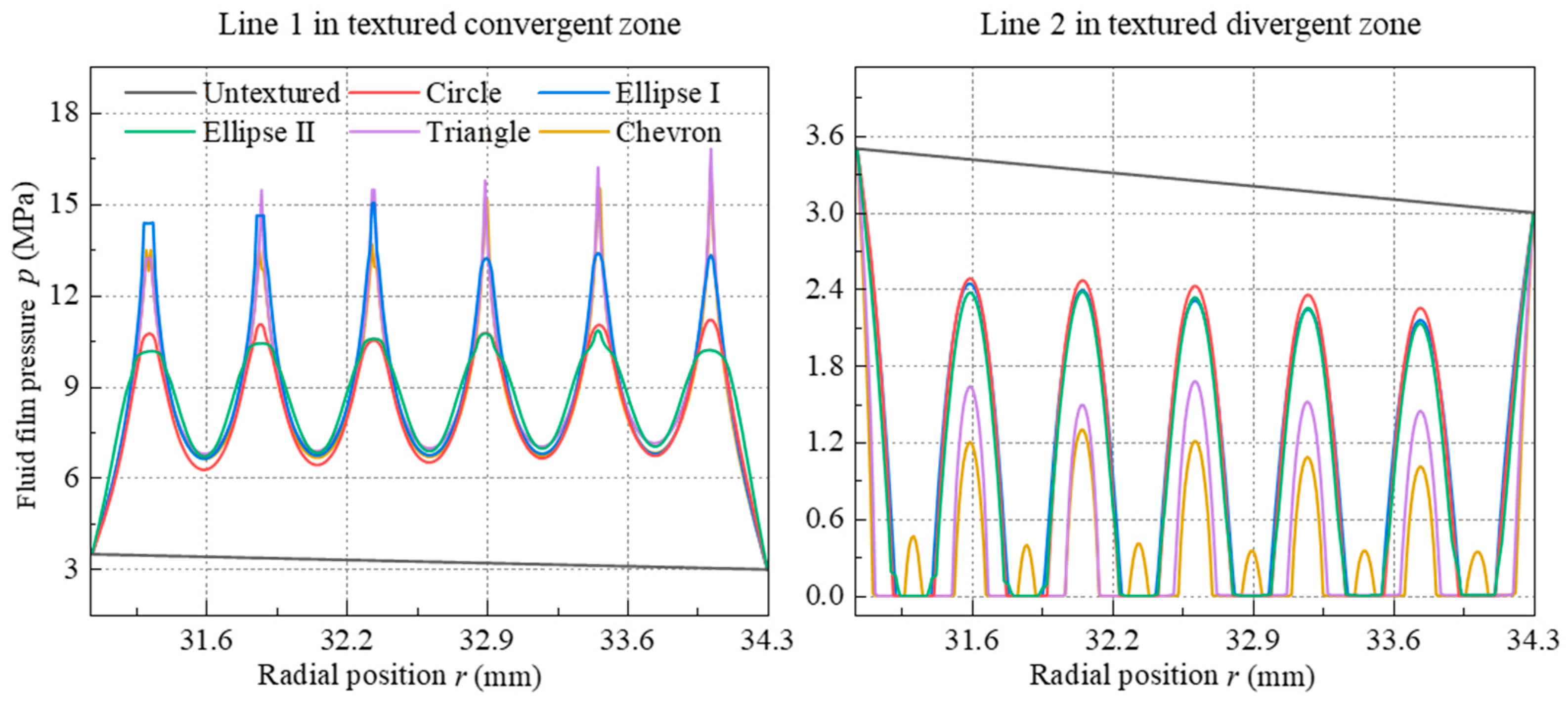
4.1. Liquid Film Pressure on End Faces

Figure 7 shows the distribution of liquid film pressure (p) in a single column of the end faces of metal seals with different shape textures under the initial conditions of environmental pressure poi = 3 MPa, pressure difference Δpi = 0.5 MPa, rotational speed ni = 200 rpm, the texture depth hp = 3 μm, and the area ratio Sp = 0.2. Different from the gradual decline in the liquid film pressure on the untextured flat end face, the presence of micro-textures on metal seals results in the formation of textured convergent and divergent zones along the rotation direction. This strong hydrodynamic effect leads to higher peak values of liquid film pressure (pmax) in the textured convergent zone, reaching approximately 3.9 to 5.62 times the environmental pressure. This magnitude far exceeds that observed in untextured metal seals. Hence, the textured end face can provide a specific bearing capacity of liquid film. As a consequence of the rotational shear exerted on the end faces, the fluid density and pressure in the divergent zone of the textured liquid film significantly decrease, leading to the occurrence of cavitation at the textured zones. The extent of cavitation, which varies depending on the shape of the textures, accounts for approximately 5% to 27% of the overall texture area.
The middle intercepting lines 1 and 2 of the textured convergent zone and divergent zone of liquid film on the end faces are extracted, respectively, as shown in Figure 7. The distributions of liquid film pressure along the two intercepting lines with radial position (r) are shown in Figure 8. For line 1, the radial liquid film pressures (p) in the convergent zone of the triangle- and chevron-shaped textures are sharper and higher than those of the circle-, ellipse I-, and ellipse II-shaped textures. Notably, the triangle-shaped textures obtain the highest peak pressure of the liquid film (pmax) among the five shape textures. In comparison to the circle- and ellipse-shaped textures, the triangle- and chevron-shaped textures exhibit a pronounced angularity in the direction of the fluid flow, thereby facilitating a more significant hydrodynamic effect in the convergent zone of the liquid film. For line 2, the liquid film pressure (p) at the bottom of these textures diminishes to zero. The distributions of liquid film pressure in the divergent zone of the circle-, ellipse I- and ellipse II-shaped textures are comparable, with their film pressure values surpassing those of the triangle and chevron textures. The sharp-angle texture on the end faces of metal seals promotes the concentration and divergence of the liquid film pressure.

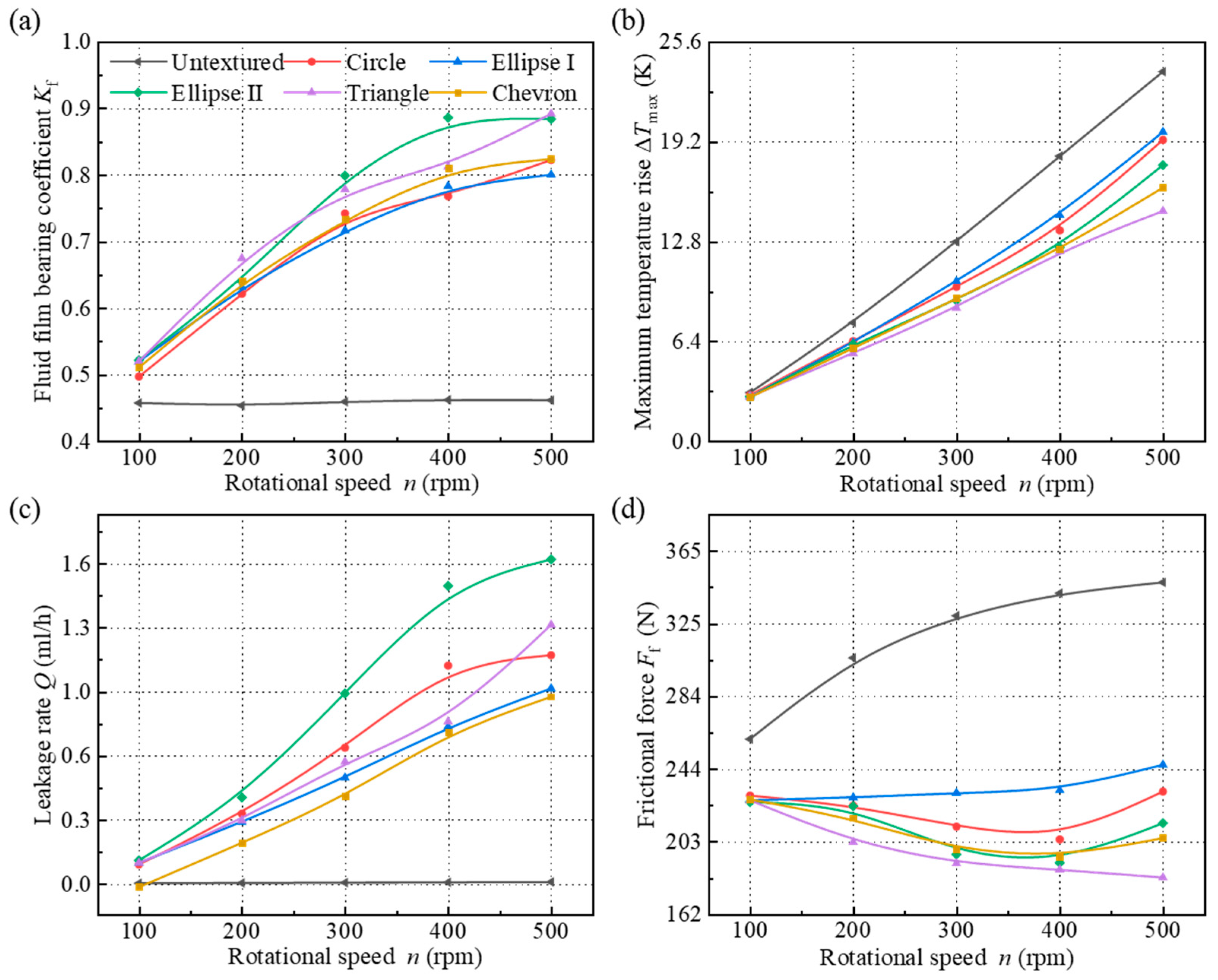
4.2. Influence of Operating Conditions on Sealing Performance

Figure 9 and Figure 10 show the key sealing parameters of metal seals with different shape textures, such as the liquid film bearing coefficient (Kf), maximum interface temperature rise (ΔTmax), leakage rate (Q), and frictional force (Ff), respectively, under different rotational speeds (n = 100~500 rpm) and environmental pressures (po = 3~69 MPa), corresponding to a formation depth of l = 260~6000 m.
As the rotational speed (n) increases from 100 rpm to 500 rpm, the hydrodynamic pressure effects and liquid film bearing coefficients (Kf) of the textured end faces gradually increase, and the leakage rates (Q) increase significantly due to the increase in film thickness. In contrast, the liquid film bearing coefficient (Kf) and leakage rate (Q) of the untextured end face undergo minimal alterations. Furthermore, the liquid film bearing capacities of the triangle- and ellipse II-textured end faces are greater than those of the other three textured end faces. However, the leakage rate (Q) of the ellipse II-textured end face exhibits the highest value among the five different textured end faces. The maximum temperature rise (ΔTmax) of both the untextured and textured end faces increase approximately linearly with the rotational speed (n), while the variation in frictional force (Ff) on the end faces differs greatly with the rotational speed (n). The untextured end face generates substantial contact pressure and frictional heat due to its minimal film thickness, resulting in significantly larger values of maximum temperature rise and frictional force (ΔTmax, Ff) compared to those of the textured end faces. The order of the texture shapes, namely, ellipse I, circle, ellipse II, chevron, and triangle, correspond to the decreasing maximum temperature rise and frictional force (ΔTmax, Ff). Specifically, when the rotational speed (n) is 500 rpm, the frictional force (Ff) of the triangle-textured end face decreases to 52.7% and to 74.5% regarding the untextured and ellipse I-textured end faces, respectively. This indicates that the triangle texture enhances the bearing capacity of the liquid film, making it easier to open the sealing end face and resulting in reduced contact frictional heat.
With there is an increase in environmental pressure (p) from 3 MPa to 69 MPa, the liquid film bearing coefficient (Kf) and leakage rates (Q) of the untextured end face increase as a result of the radial redistribution of the film thickness, leading to a notable reduction in frictional heat between the sealing rings. The liquid film bearing coefficients (Kf) of the textured end faces are larger than that of the untextured end face and gradually increase up to 98.9%. It is noteworthy that the hydrodynamic effect of the textured end faces diminishes gradually when the environmental pressure is p ≥ 30 MPa, resulting in liquid film bearing coefficients that are no longer superior to that of the untextured end face. This can be attributed to the substantial alterations in film thickness and contact pressure, leading to a fluctuation in the leakage rates (Q) of the circle-, triangle- and chevron-textured end faces. The leakage rates (Q) initially decrease and then increase with the environmental pressure (p), ultimately reaching the minimum values at p = 11 MPa. The maximum temperature rise and frictional force (ΔTmax, Ff) of these three textured end faces decrease with the environmental pressure (p), consistently remaining lower than those of the untextured end face. It can effectively weaken the wear of the sealing end faces. The leakage rates (Q) of the ellipse I- and ellipse II-textured end faces gradually decrease to a stable value with the environmental pressure (p). However, except for the low-pressure condition, the ellipse I- and ellipse II-textured end faces exhibit higher maximum temperature rise and frictional force (ΔTmax, Ff) compared to the untextured, circle-, triangle-, and chevron-textured end faces. This can be attributed to the significant shear effect of the liquid film on the ellipse-textured end faces, resulting in an inferior sealing performance under high-pressure conditions. Therefore, the influence of surface textures on hydrodynamic pressure is crucial for enhancing the sealing efficacy in low-pressure conditions. As the environmental pressure increases, the hydrodynamic pressure effect induced by the textures weakens, while the circle-, triangle- and chevron-shaped textures still help to reduce the contact pressure and frictional heat of the sealing rings.

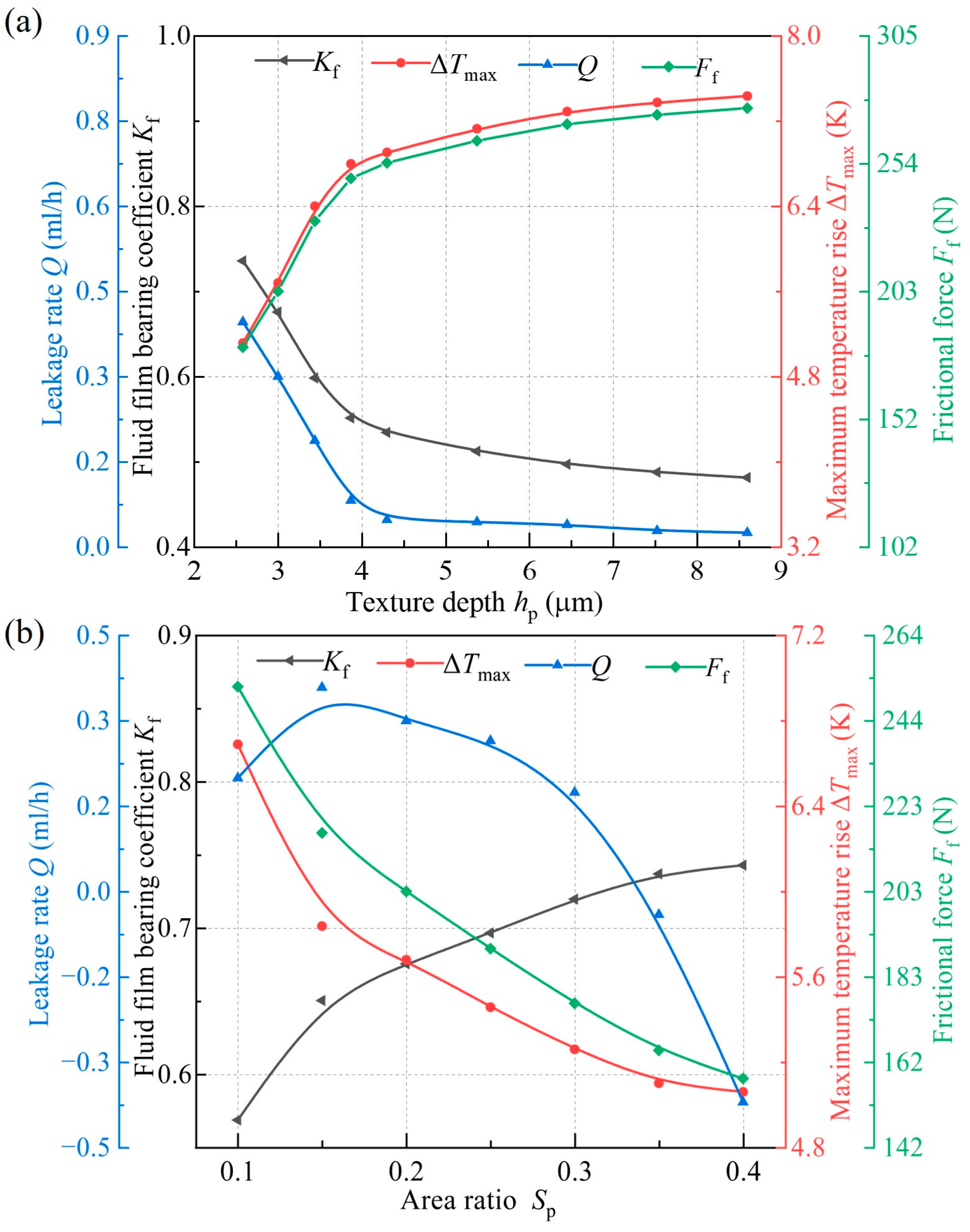
4.3. Influence of Texture Parameters on Sealing Performance

Based on the above comparisons, the triangle-textured end face has the best comprehensive sealing performance among the five textured end faces. Considering that the hydrodynamic effect is closely related to the texture parameters, the influences of texture depth (hp) and area ratio (Sp) are further investigated.
Figure 11 and Figure 12 show the fluid film pressure and sealing parameters of metal seals under different texture depths (hp = 2.6~8.6 μm) and area ratios (Sp = 0.1 ~ 0.4), respectively. With the increase in the texture depth (hp), the hydrodynamic pressure effect resulting from the fluid extrusion in the textured convergent zone and the cavitation area caused by the fluid shear in the textured divergent zone of the liquid film both weaken. The pressure distribution of the fluid film on the triangle-textured end face becomes more uniform with the increase in hp. Additionally, the peak value of liquid film pressure (pmax) at hp = 8.6 μm is 71.6% lower compared to hp = 2.6 μm. Consequently, the liquid film bearing coefficient (Kf) and the opening degree of the sealing end face decrease significantly. In particular, the leakage rate (Q) of metal seals reduces rapidly to less than 0.1 mL·h−1. However, the maximum temperature rise and frictional force (ΔTmax, Ff) of the triangle-textured end face increase and gradually stabilize after hp ≥ 4.3 μm.
As the area ratio (Sp) increases from 0.1 to 0.4, the textured convergent zone and divergent zone of the liquid film continue to expand. This expansion is accompanied by a heightened hydrodynamic effect and shear effect, resulting in a 41.9% increase in the peak pressure (pmax) and a 17.4% increase in the bearing coefficient of the liquid film (Kf) on the triangle-textured end face. Accordingly, the maximum temperature rise and frictional force (ΔTmax, Ff) decrease with the attenuated contact area. It is noteworthy that the leakage rate (Q) of the metal seals increases first and then decreases with the area ratio (Sp). Eventually, a phenomenon known as ‘negative leakage’ emerges. Specifically, when Sp increases from 0.3 to 0.35, the leakage rate (Q) changes from positive to negative, and the ‘zero leakage’ of metal seals can be obtained theoretically at Sp = 0.34 and hp = 3 μm. Increasing the texture area ratio makes the textures gradually approach the outer diameter side of the end faces, resulting in a certain degree of directional pumping effects. This leads to the invasion of the external drilling mud and accelerates the wear failure on the end faces of metal seals.

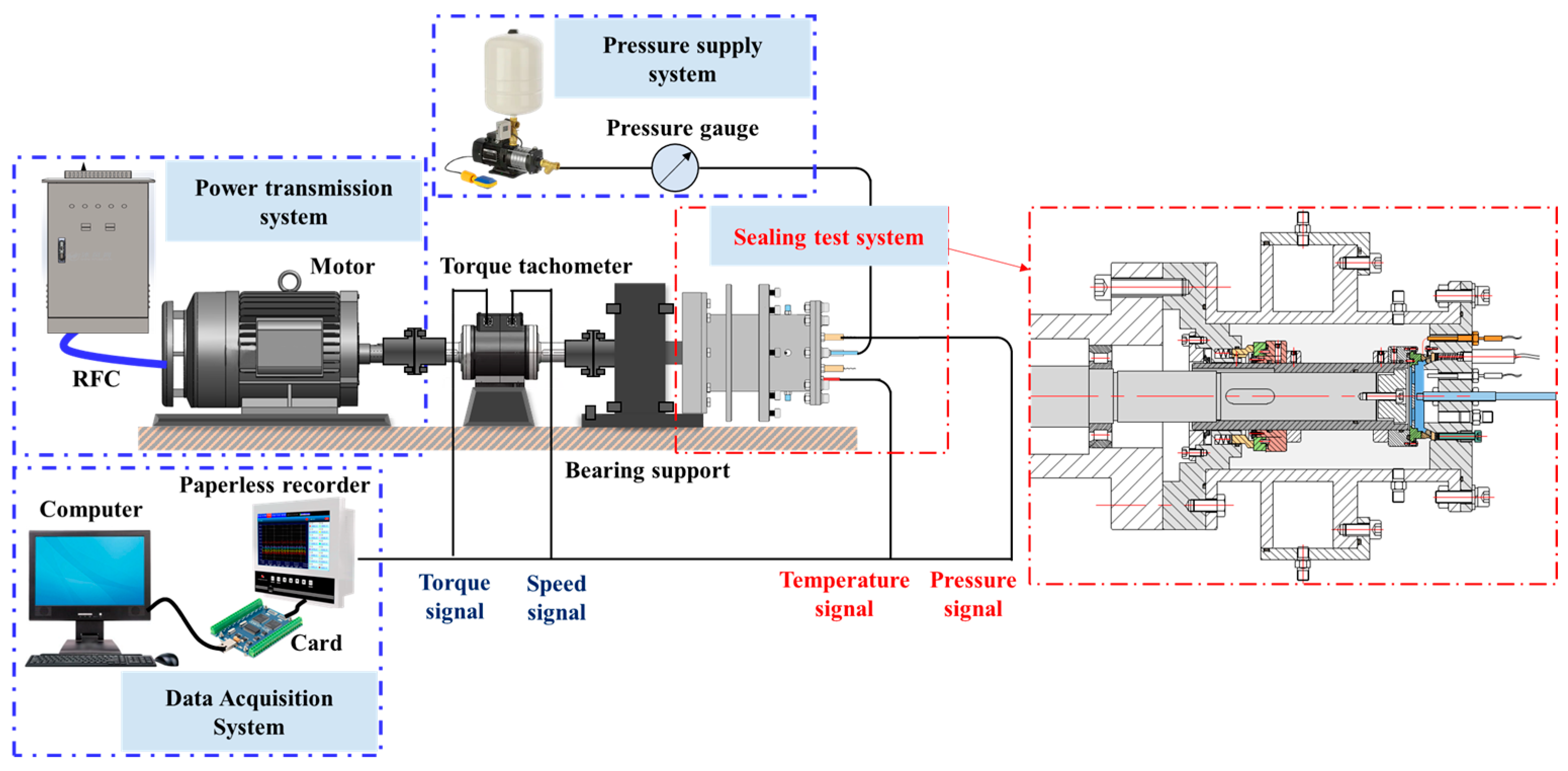
4.4. Experimental Validations

A performance test bench was constructed to validate the accuracy of the simulation results for surface-textured metal seals in roller cone bits, as shown in Figure 13. The test bench mainly consists of the power transmission, pressure supply, sealing test, and data acquisition systems. The power transmission system controls the rotating speed of the motor shaft by adjusting the frequency of the inverter cabinet. The pressure supply system provides the sealing medium for the test cavities. The sealing test system includes a metal sealing cavity and an auxiliary sealing cavity. The two sealing cavities collaborate with the sleeve and the end cover to form the inner and outer cavities, characterized by a specific pressure differential. The data acquisition system can dynamically collect the sealing performance parameters including sealing pressure, end face temperature, and other relevant signals during the test.
Laser processing technology, one of the most widely used surface texture processing technologies, was used to process the surface textures of various shapes on the stator of metal seals. A flowchart of the surface texture processing of metal seals is shown in Figure 14. The materials of the rotor and stator in the experiment are the same as those in the numerical calculation, that is, alloy steel 20CrNiMo. The texture shapes of circle, ellipse I, ellipse II, triangle, and chevron with an area ratio Sp = 0.2 are adopted and compared with the untextured flat end face of metal seals. The circumferential and radial arrangements of the textures in the experiment are consistent with those in the numerical calculation.
Considering the safety and feasibility of the test, a comprehensive performance test of metal seals with different shape textures was carried out under the pressure difference of Δp = 0.5 MPa, the sealing medium of water, and the rotational speed range of n = 100~500 rpm. During the experiment, we adjusted the rotational speed n to 100, 200, 300, 400, and 500 rpm sequentially after the temperature on the end face stabilized at each stage. The test time took about 30 min. After the experiment, the surface wear morphology of the sealing rings was measured using a 3D laser microscope to verify the accuracy of the multi-field coupling simulation of surface-textured metal seals.
Figure 15 shows the time-varying curves of the temperature rise of the untextured and textured end faces of metal seals under different rotational speeds (n). Figure 16 compares the interface temperature rise of the untextured and textured end faces of metal seals obtained via numerical simulation and experiments under the same experimental conditions. With an increase in rotational speed (n) from 100 rpm to 500 rpm, the contact frictional heat and viscous shear heat between the end faces of the rotor and stator increase. Both the numerical and experimental average values of the interface temperature rise (ΔT) increase. Notably, the values and change gradient of the temperature rise for the untextured end face are significantly higher than those of the textured end faces, and it requires a lengthier duration for the temperature rise to reach stability. The experimental results prove that the textures on the end faces can indeed reduce the asperity friction and temperature rise of the metal sealing rings. For the textured end faces, the experimental temperature rise of the ellipse I- and ellipse II-textured end faces are comparable to those of the circle- and chevron-textured end faces, respectively. Moreover, when the rotational speed (n) reaches 500 rpm, the triangle-textured end face has the lowest temperature rise among these textured end faces. The observed phenomenon aligns with the predominant dynamic pressure impact of triangle textures as determined through numerical simulation. In contrast, the experimental values of interface temperature rise (ΔT) are lower than the numerical values. This discrepancy can be attributed to the steady-state assumptions employed in the numerical simulations of metal seals, whereas actual operational tests are subject to diverse external factors including shaft vibration, fluctuations in film thickness, and interference in heat transfer. In general, the multi-field coupling numerical method of metal seals in this study is suitable for reflecting the sealing performance and its variation law with different parameters.
The worn surface morphologies of the inner diameter (ID) and outer diameter (OD) side of the rotor and stator with the untextured and textured end surfaces are shown in Figure 17. The rotor and stator with an untextured end face experience significant wear due to the insufficient bearing capacity of the liquid film. The direct contact between the end faces exacerbates the semi-dry friction state of the untextured metal seals, and the seals are close to failure after the friction pairs run for a certain time. Affected by the convergent sealing gap at low environmental pressure, the wear on the OD of the rotor and stator is generally more serious than that on the ID of the rotor and stator. Similar to some contact mechanical seals [45,46], obvious wear grooves parallel to the sliding direction and material losses occur on the ID and OD of untextured end faces. Corresponding to the changes in temperature rise with the rotational speed, clear indications of adhesive wear are evident on the untextured surfaces of the rotor and stator. A portion of the wear debris adheres to the untextured end face, exacerbating the wear of sealing rings. The existence of textures makes a thicker lubricating liquid film form between the end faces so that the wear depth and range of the textured end faces of the rotor and stator significantly weaken in a mixed friction state. Different degrees of wear debris, grooves, and material shedding can be observed on the five textured end faces. Take the circle-textured end faces as an example. Deep grooves and pits are generated on the OD of the stator during the frictional process, and the wear debris is transferred and accumulated on the OD of the rotor. The grooves on the ID are shallower than those on the OD of the rotor and stator. Due to the ability to produce a greater liquid film bearing capacity, the triangle-textured end faces have a greater opening degree between the rotor and stator. This improvement significantly enhances the wear resistance of the friction pairs. Black abrasive grooves and material attachment appear on the OD of the rotor, and the wear scars and material shedding on the ID of the rotor are greatly reduced. Among the five different shapes of textured end faces, the triangle-textured end faces demonstrate the smallest wear area and quantity. Therefore, the texture design of metal seals is conducive to reducing the temperature rise, friction, and wear of the end faces and has the effect of accommodating abrasive particles and external intrusion mud.

5. Conclusions

This study employs numerical simulation and experimental validation to examine the effectiveness of surface textures applied to the metal seals of roller cone bits. The liquid film state, sealing performance, and wear characteristics of surface-textured metal seals are studied, considering the various texture shapes of circle, ellipse I (horizontal), ellipse II (vertical), triangle, and chevron and the different texture parameters of depth and area ratio. With the discussions above, some meaningful results can be achieved.
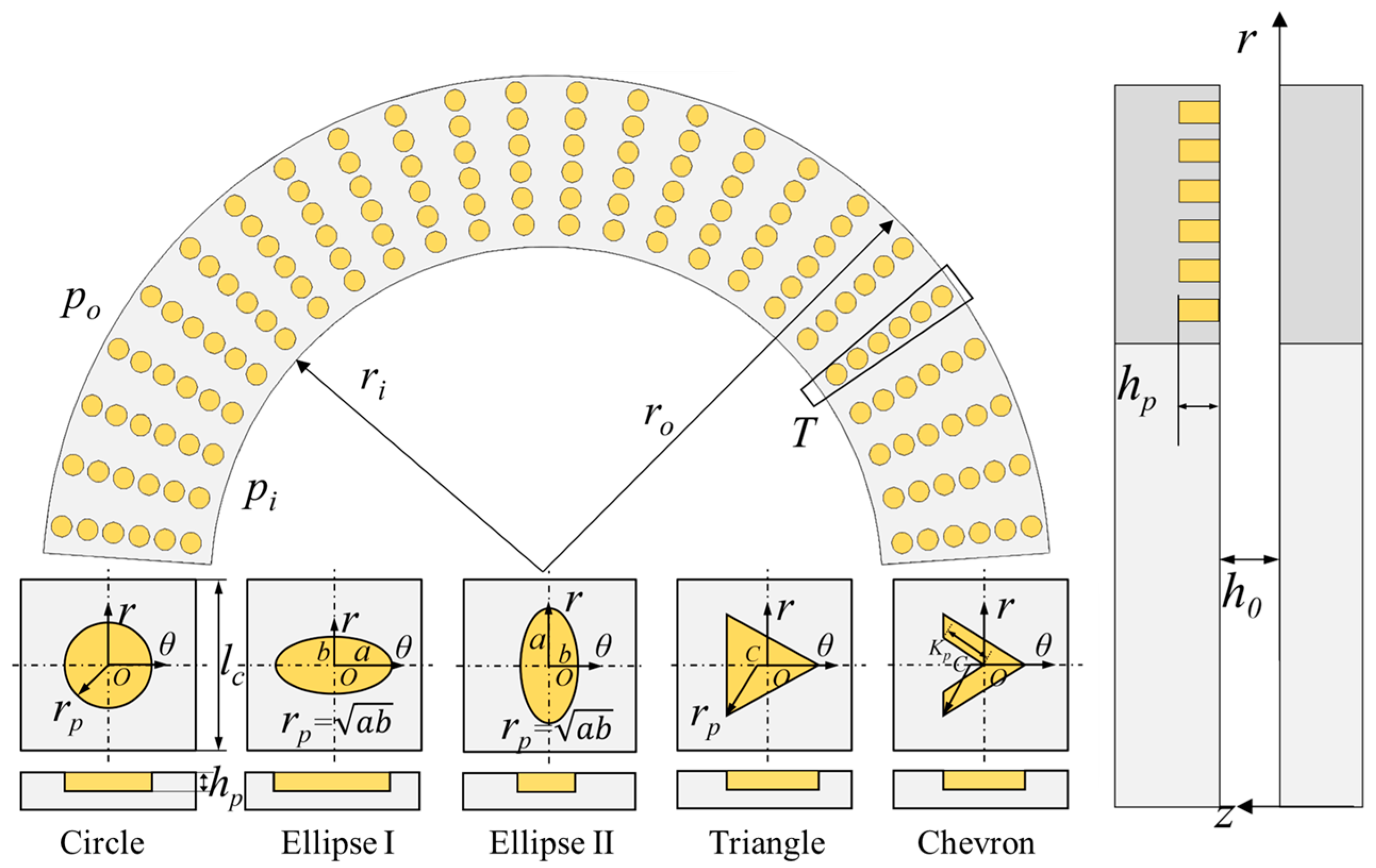
  • A comprehensive multi-field coupling numerical model for the surface-textured metal seals of roller bits is established, taking into account the influence of surface roughness, asperity contact, micro-deformation, and cavitation. Under the initial condition of poi = 3 MPa and ni = 200 rpm, the textured convergent zones and divergent zones of the liquid film are formed along the rotational direction on end faces with different shape textures. The sharp-angle textures, including triangle and chevron textures, can produce a stronger hydrodynamic pressure effect on the end faces of metal seals. The cavitation area of different shape textures accounts for about 5% to 27% of the total texture area.
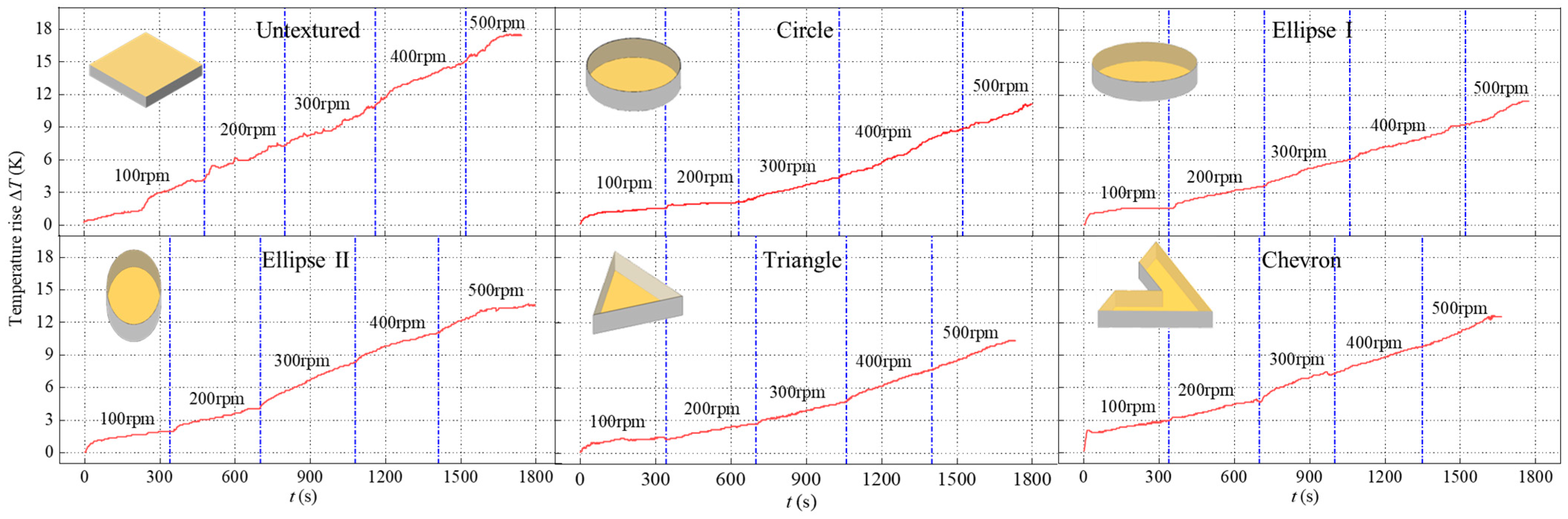
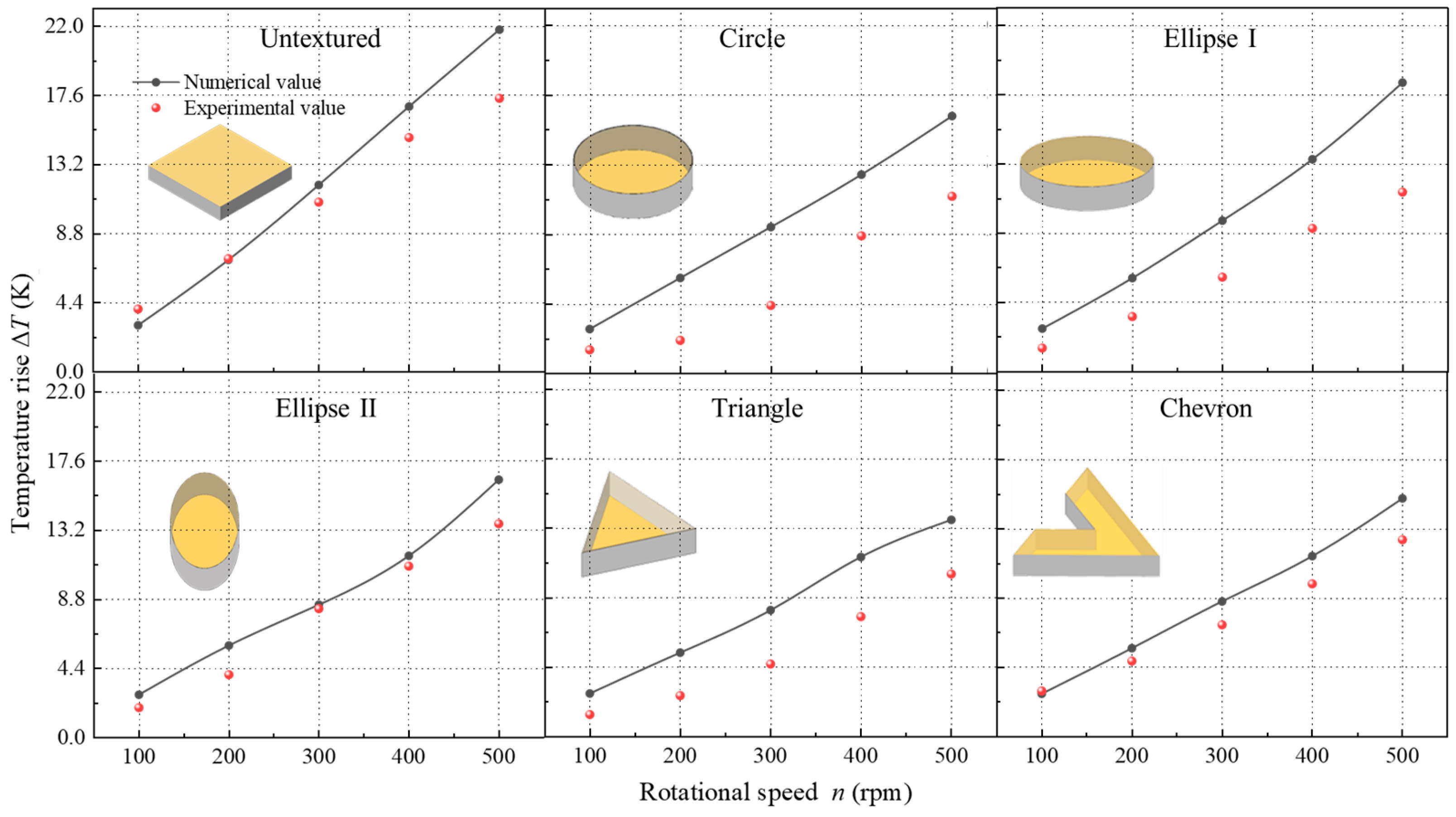
  • The liquid film bearing coefficient, leakage rate, and maximum temperature rise of the metal seals with five shape textures increase with an increase in the rotational speed (n) from 100 rpm to 500 rpm. The temperature rise and frictional force of the textured end faces under different rotational speeds are significantly improved when compared to the untextured flat end face, particularly in the case of the triangle-textured end face. As the environmental pressure increases, the hydrodynamic pressure effect induced by the textures weakens, although the textures continue to contribute to a reduction in the contact pressure and frictional heat of the sealing rings. However, when the environmental pressure is p ≥ 30 MPa, the textured end face gradually loses its advantage in the sealing performance of metal seals.
  • The liquid film characteristics and sealing performance of triangle-textured end faces are significantly affected by texture parameters, specifically the depth and area ratio. The hydrodynamic pressure effect and cavitation phenomenon intensify with a decrease in the depth (hp) from 8.6 μm to 2.6 μm and with an increase in the area ratio (Sp) from 0.1 to 0.4. Consequently, the maximum temperature rise and frictional force (ΔTmax, Ff) decrease with the area ratio (Sp). The effect of depth (hp) on the sealing parameters is significantly weakened when hp ≥ 4.3 μm. The leakage rate (Q) changes from positive to negative in the range of Sp = 0.3~0.35, and the optimal texture parameters of Sp = 0.34 and hp = 3 μm can achieve an ideal state of ‘zero leakage’.
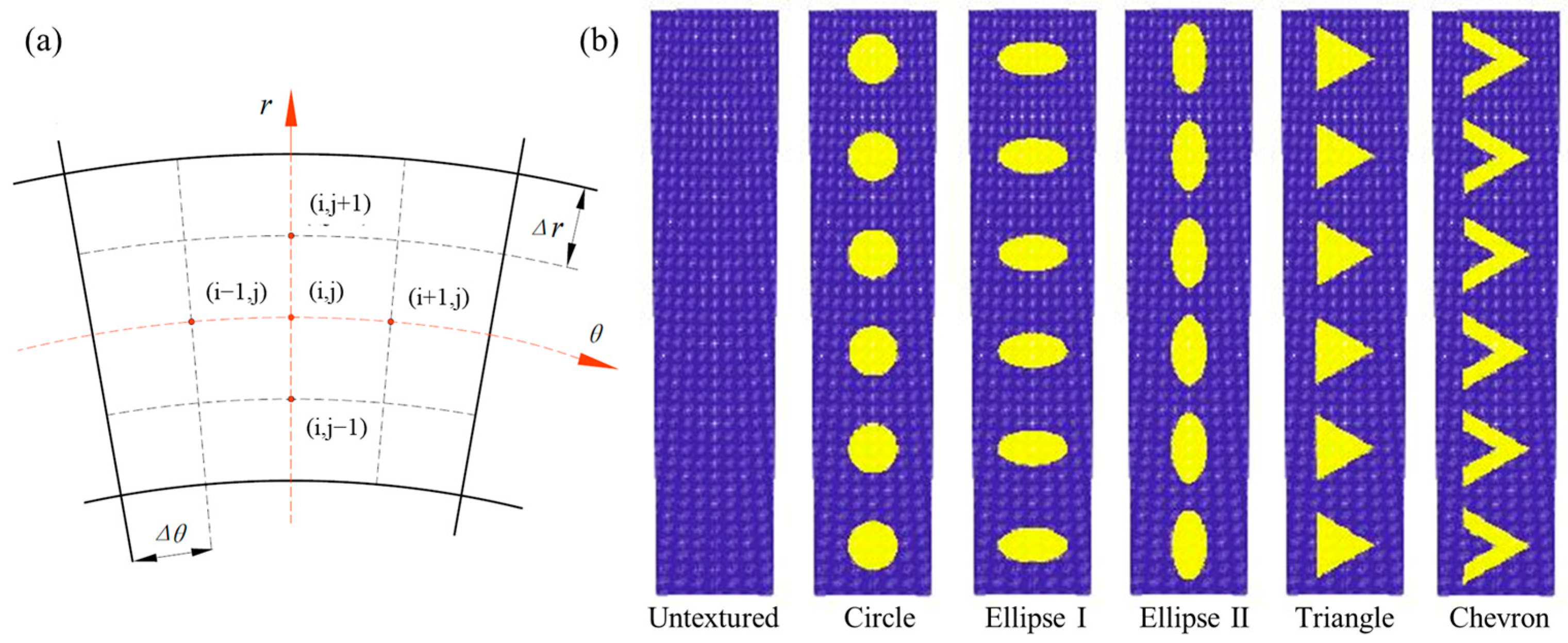
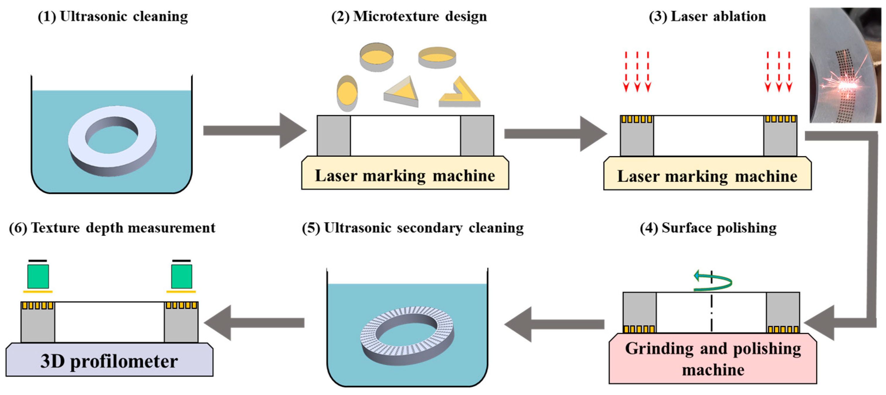
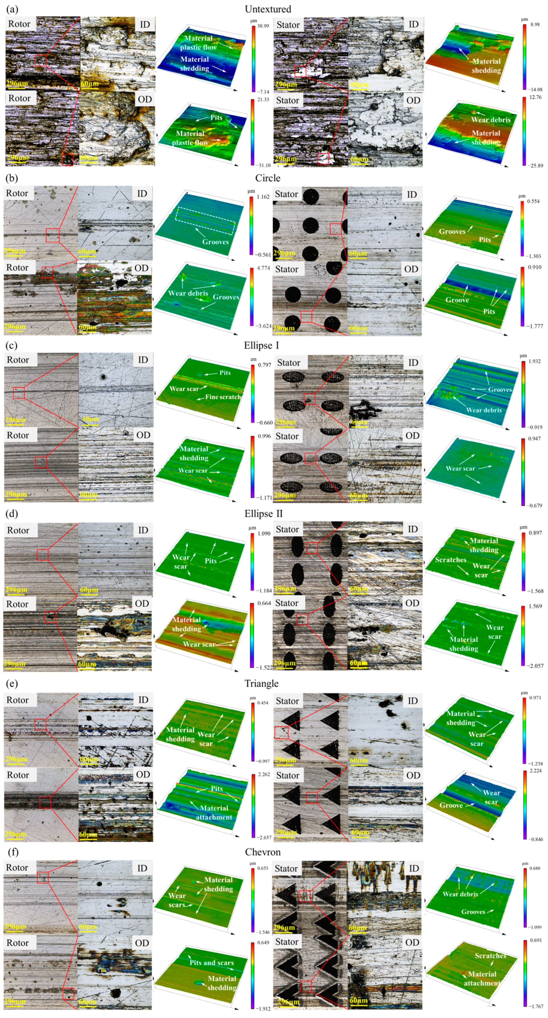
  • A sealing performance test bench of surface-textured metal seals is constructed to validate the accuracy of multi-field coupling simulation. The application of surface textures to metal seals offers advantages in terms of reducing temperature rise, friction and wear on the end faces. The untextured and textured end faces are in a semi-dry friction and mixed friction state during the test, respectively, resulting in the occurrence of abrasive wear and adhesive wear on the end faces of the rotor and stator. The triangle texture has proven to have the best hydrodynamic lubrication and wear resistance among the five shape textures.
In further studies, the test device of the metal seals will continue to be improved to better simulate the downhole drilling conditions and systematically study the influence of surface texture parameters on the sealing performance.

Author Contributions

Conceptualization, Y.M., X.M. and X.P.; methodology, Z.Y.; software, Z.L.; validation, Z.L. and J.J.; formal analysis, Y.M. and X.M.; investigation, Y.M. and Z.Y.; data curation, Y.M. and Z.Y.; writing—original draft preparation, Y.M. and Z.L.; writing—review and editing, X.P.; supervision, X.P.; funding acquisition, Y.M. All authors have read and agreed to the published version of the manuscript.

Funding

This research was funded by the National Natural Science Foundation of China, grant number 52375211 and 51975527.

Data Availability Statement

All relevant data are presented in the paper.

Conflicts of Interest

The authors declare no conflicts of interest.

References

  1. Wang, C.; Wang, X.; Li, S.; Jiao, Y.; Yang, R.; Li, G. Evaluation method for tooth wear of roller bits based on the fractal dimension of the rock surface. J. Petrol. Sci. Eng. 2022, 210, 110039. [Google Scholar] [CrossRef]
  2. Naganawa, S. Feasibility study on roller-cone bit wear detection from axial bit vibration. J. Petrol. Sci. Eng. 2012, 82–83, 140–150. [Google Scholar] [CrossRef]
  3. Li, B.; Liu, J.; Lu, D.; Wu, M.; Chen, H. Optimization of single metal seal structure of cone bit. Lubr. Eng. 2019, 44, 98–102. [Google Scholar]
  4. Aminfar, O. Innovations in Rotary Drill Bit Design to Reduce Vibration and Improve Durability. Master’s Thesis, University of Waterloo, Waterloo, ON, Canada, 2008. [Google Scholar]
  5. Elmgerbi, A.; Thonhauser, G. Holistic autonomous model for early detection of downhole drilling problems in real-time. Process Saf. Environ. 2022, 164, 418–434. [Google Scholar] [CrossRef]
  6. Keller, A.M.; Feng, T.H.; Demirer, N.; Darbe, R.; Chen, D.M. Rate of penetration estimation downhole with machine learning for drilling position control. Geoenergy Sci. Eng. 2022, 224, 211593. [Google Scholar] [CrossRef]
  7. Al-Wahedi, T.; Hay, M.A.; Waheed, T.; Grimes, T. New slim hole technology maximizes productivity in middle east horizontal drilling programs. In Proceedings of the SPE/IADC Drilling Conference, SPE-92376-MS, Amsterdam, The Netherlands, 23–25 February 2005. [Google Scholar]
  8. Zhou, Y.; Hu, J.; Tan, B.; Jiang, Y.; Tang, Y. Wear of spiral seal cone bit in complex formations. SPE J. 2021, 26, 3575–3590. [Google Scholar] [CrossRef]
  9. Etsion, I. State of the art in laser surface texturing. J. Tribol. 2005, 127, 248–253. [Google Scholar] [CrossRef]
  10. Gropper, D.; Wang, L.; Harvey, T.J. Hydrodynamic lubrication of textured surfaces: A review of modeling techniques and key findings. Tribol. Int. 2016, 94, 509–529. [Google Scholar] [CrossRef]
  11. Chen, T.; Ji, J.; Fu, Y.; Yang, X.; Fu, H.; Fang, L. Tribological performance of UV picosecond laser multi-scale composite textures for C/SiC mechanical seals: Theoretical analysis and experimental verification. Ceram. Int. 2021, 47, 23162–23180. [Google Scholar] [CrossRef]
  12. Xiong, S.; Salant, R.F. A numerical model of a rock bit bearing seal. Tribol. Trans. 2000, 43, 542–548. [Google Scholar] [CrossRef]
  13. Xiong, S.; Salant, R.F. A dynamic model of a contacting mechanical seal for down-hole tools. J. Tribol. 2003, 125, 469–479. [Google Scholar] [CrossRef]
  14. Ma, Y.; Yuan, Z.; Ni, Y.; Meng, X.; Peng, X. Performance prediction and multi-objective optimization of metal seals in roller cone bits. J. Petrol. Sci. Eng. 2022, 208, 109316. [Google Scholar] [CrossRef]
  15. Ma, Y.; Xu, Y.; Chen, Y.; Meng, X.; Peng, X. Dynamic characteristics of metal seals in roller cone bits. Lubricants 2022, 10, 280. [Google Scholar] [CrossRef]
  16. Etsion, I.; Kligerman, K.; Halperin, G. Analytical and experimental investigation of laser-textured mechanical seal faces. Tribol. Trans. 1999, 42, 511–516. [Google Scholar] [CrossRef]
  17. Etsion, I.; Halperin, G. A laser surface textured hydrostatic mechanical seal. Tribol. Trans. 2002, 45, 430–434. [Google Scholar] [CrossRef]
  18. Brunetiere, N.; Tournerie, B. Numerical analysis of a surface-textured mechanical seal operating in mixed lubrication regime. Tribol. Int. 2012, 49, 80–89. [Google Scholar] [CrossRef]
  19. Yang, X.; Peng, X.; Meng, X.; Jiang, J.; Wang, Y. Thermo-elasto-hydrodynamic analysis of triangular textured mechanical face seals. J. Zhejiang Univ.-Sci. A 2019, 20, 864–881. [Google Scholar] [CrossRef]
  20. Qiu, Y.; Khonsari, M.M. Experimental investigation of tribological performance of laser textured stainless steel rings. Tribol. Int. 2011, 44, 635–644. [Google Scholar] [CrossRef]
  21. Dingui, K.; Brunetière, N.; Bouyer, J.; Adjemout, M. Surface texturing to reduce temperature in mechanical seals. Tribol. Online 2020, 15, 222–229. [Google Scholar] [CrossRef]
  22. Grimes, B.; Kirkpatrick, B. Step change in performance: Upgraded bit technology significantly improves drilling economics in GOM motor applications. In Proceedings of the SPE Annual Technical Conference and Exhibition, San Antonio, TX, USA, 24–27 September 2006. [Google Scholar]
  23. Lin, C. Oil and Gas Drilling Bit Tribology. In Encyclopedia of Tribology; Springer: New York, NY, USA, 2013; pp. 2467–2475. [Google Scholar]
  24. Liu, Z.; Kuang, Y.; Wang, Y. Research on working principle of a roller bit’s seal testing machine. Mach. Des. Manuf. 2009, 47, 191–193. [Google Scholar]
  25. Qiu, M.; Delic, A.; Raeymaekers, B. The effect of texture shape on the load-carrying capacity of gas-lubricated parallel slider bearings. Tribol. Lett. 2012, 48, 315–327. [Google Scholar] [CrossRef]
  26. Adjemout, M.; Andrieux, A.; Bouyer, J.; Brunetière, N.; Marcos, G.; Czerwiec, T. Influence of the real dimple shape on the performance of a surface textured mechanical seal. Tribol. Int. 2017, 115, 409–416. [Google Scholar] [CrossRef]
  27. Patir, N.; Cheng, H.S. An average flow model for determining effects of three-dimensional roughness on partial hydrodynamic lubrication. J. Lubri. Technol. 1978, 100, 12–17. [Google Scholar] [CrossRef]
  28. Patir, N.; Cheng, H.S. Application of average flow model to lubrication between rough sliding surfaces. J. Lubri. Technol. 1979, 101, 220–229. [Google Scholar] [CrossRef]
  29. Meng, X.; Bai, S.; Peng, X. Lubrication film flow control by oriented dimples for liquid lubricated mechanical seals. Tribol. Int. 2014, 77, 132–141. [Google Scholar] [CrossRef]
  30. Yu, H.; Wang, X.; Zhou, F. Geometric shape effects of surface texture on the generation of hydrodynamic pressure between conformal contacting surfaces. Tribol. Lett. 2010, 37, 123–130. [Google Scholar] [CrossRef]
  31. Jakobsson, B.; Floberg, L. The finite journal bearing considering vaporization. Trans. Chalmers Univ. Technol. 1957, 190, 1–116, Corpus ID: 136822854. [Google Scholar]
  32. Olsson, K. Cavitation in dynamically loaded bearings. Trans. Chalmers Univ. Technol. 1965, 308, 1–60, Corpus ID: 135904611. [Google Scholar]
  33. Meng, X.; Tu, Z.; Ma, Y.; Jiang, J.; Peng, X. Topology optimization of liquid lubricating zero-leakage mechanical face seals. Tribol. Int. 2022, 169, 107490. [Google Scholar] [CrossRef]
  34. Shen, C.; Khonsari, M.M. Texture shape optimization for seal-like parallel surfaces: Theory and experiment. Tribol. Trans. 2016, 59, 698–706. [Google Scholar] [CrossRef]
  35. Xiong, S.; Wang, Q. Steady-state hydrodynamic lubrication modeled with the Payvar-Salant mass conservation model. J. Tribol. 2012, 134, 031703. [Google Scholar] [CrossRef]
  36. Abbott, E.J.; Firestone, F.A. Specifying surface quality-A method based on accurate measurement and comparison. J. Mech. Eng. 1933, 55, 569–572. [Google Scholar]
  37. Harp, S.R.; Salant, R.F. Analysis of mechanical seal behavior during transient operation. J. Tribol. 1998, 120, 191–197. [Google Scholar] [CrossRef]
  38. Liu, J. Research on Sealing Structure of New Roller Bit Bearing. Master’s Thesis, Degree-Southwest Petroleum University, Chengdu, China, 2018. [Google Scholar]
  39. Qu, J.; Chen, G.; Yang, Y.W. Finite element analysis of rubber sealing ring resilience behavior. Adv. Mater. Res. 2013, 705, 410–414. [Google Scholar] [CrossRef]
  40. Kim, B.; Lee, S.B.; Lee, J.; Cho, S.; Park, H.; Yeom, S.; Park, S.H. A comparison among Neo-Hookean model, Mooney-Rivlin model, and Ogden model for chloroprene rubber. Int. J. Precis. Eng. Man. 2012, 13, 759–764. [Google Scholar] [CrossRef]
  41. Ruan, B.; Salant, R.F.; Green, I. A mixed lubrication model of liquid/gas mechanical face seals. Tribol. Trans. 1997, 40, 647–657. [Google Scholar] [CrossRef]
  42. Li, Y.; Pei, X. Investigation on tribological behaviors of surface micro-forming 20CrNiMo steel under laser shock processing. Laser Technol. 2012, 36, 814–817. [Google Scholar]
  43. Zhong, L.; Wei, G.; Wang, G.; He, X.; Liao, Y.; Xie, N. Effects of femtosecond laser texture on the tribological properties of 20CrNiMo/beryllium bronze tribo-pairs of rock bit sliding bearings under non-Newtonian lubrication. Proc. Inst. Mech. Eng. Part J J. Eng. Tribol. 2019, 233, 1293–1305. [Google Scholar] [CrossRef]
  44. Wang, Y.; Wu, J.; Li, Z.; Xu, L. Effect of slip position on the hydrodynamic performance of liquid film seal. Ind. Lubri. Tribol. 2021, 73, 405–413. [Google Scholar] [CrossRef]
  45. Li, X.; Yang, Z.; Xu, J.; Chen, R.; Yang, H. The fractal leakage model of contact mechanical seals considering wear and thermal deformation. J. Braz. Soc. Mech. Sci. 2019, 41, 521. [Google Scholar] [CrossRef]
  46. Ni, X.; Sun, J.; Ma, C.; Zhang, Y. Wear model of a mechanical seal based on piecewise Fractal Theory. Fractal Fract. 2023, 7, 251. [Google Scholar] [CrossRef]
Figure 1. Geometric model of roller cone bit and metal seals. (a) Roller cone bit; (b) Metal seals.
Lubricants 12 00015 g001
Figure 2. Surface texture patterns on the stator.
Lubricants 12 00015 g002
Figure 3. Control volume nodes and grids. (a) Control volume nodes; (b) Control volume grids.
Lubricants 12 00015 g003
Figure 4. Finite element model and boundary conditions of metal seals.
Lubricants 12 00015 g004
Figure 5. Influence factor matrices under initial conditions.
Lubricants 12 00015 g005
Figure 6. Flowchart of multi-field coupled numerical model.
Lubricants 12 00015 g006
Figure 7. Distribution contours of fluid film pressure with different shape textures.
Lubricants 12 00015 g007
Figure 8. Distributions of film pressure in textured zone.
Lubricants 12 00015 g008
Figure 9. Sealing performance of metal seals under different rotational speeds. (a) Fluid film bearing coefficient; (b) Maximum temperature rise; (c) Leakage rate; (d) Frictional force.
Lubricants 12 00015 g009
Figure 10. Sealing performance of metal seals under different environmental pressures. (a) Fluid film bearing coefficient; (b) Maximum temperature rise; (c) Leakage rate; (d) Frictional force.
Lubricants 12 00015 g010
Figure 11. Contours of fluid film pressure under different texture parameters. (a) Texture depth; (b) Area ratio.
Lubricants 12 00015 g011
Figure 12. Sealing performance under different texture parameters. (a) Texture depth; (b) Area ratio.
Lubricants 12 00015 g012
Figure 13. Performance test bench of metal seals.
Lubricants 12 00015 g013
Figure 14. Surface texture processing.
Lubricants 12 00015 g014
Figure 15. Time-varying curves of temperature rise with different textures.
Lubricants 12 00015 g015
Figure 16. Comparison of temperature rises with different textures.
Lubricants 12 00015 g016
Figure 17. Worn surface morphology of rotor and stator with different shape textures. (a) Untextured; (b) Circle; (c) Ellipse I; (d) Ellipse II; (e) Triangle; (f) Chevron.
Lubricants 12 00015 g017
Table 1. Structural and operating parameters of metal seals.
Structural ParametersValuesOperating ParametersValues
Inner diameter of stator rd (mm)29Environmental pressure po (MPa)3~69
Outer diameter of rotor rs (mm)34.5Pressure difference Δp (MPa)0.5
Sealing inner diameter ri (mm)31Environmental temperature To (°C)8~180
Sealing outer diameter ro (mm)34.3Rotational speed n (rpm)100~500
Wedging angle α (°)5Density of lubricant oil (kg/m3)861
Incline angle β (°)65Density of drilling mud (kg/m3)1742
Surface roughness σ (μm)0.2Viscosity of lubricant oil (Pa·s)0.002~0.189
Dry friction coefficient fo0.08Viscosity of drilling mud (Pa·s)0.02~0.03
Table 2. Structural parameters of textures.
Type3-D ShapeDefinition [25]ParameterValue
Circle Lubricants 12 00015 i001 S p = π r p 2 l c   2 Texture depth hp (μm)2.6~8.6
Ellipse ILubricants 12 00015 i002 S p = π ab l c   2 Texture control unit lc (μm)550
Ellipse IILubricants 12 00015 i003 S p = π ab l c   2 Column number T300
TriangleLubricants 12 00015 i004 S p =   3 3 r p 2 4 l c   2 Texture area ratio Sp0.1~0.4
ChevronLubricants 12 00015 i005 S p = 3 3 1 - K p r p 2 4 l c   2 Texture quantity Nt6
Disclaimer/Publisher’s Note: The statements, opinions and data contained in all publications are solely those of the individual author(s) and contributor(s) and not of MDPI and/or the editor(s). MDPI and/or the editor(s) disclaim responsibility for any injury to people or property resulting from any ideas, methods, instructions or products referred to in the content.

