Article

Deterministic Simulation of Surface Textures for the Piston Ring/Cylinder Liner System in a Free Piston Linear Engine

by
Felipe Kevin Correia Luz
1,
Francisco J. Profito
2,
Marcelo Braga dos Santos
3,
Samuel A. N. Silva
3 and
Henara Lillian Costa
1,3,*
1
School of Engineering, Universidade Federal do Rio Grande, Campus Carreiros, Rio Grande 96203 900, Brazil
2
Department of Mechanical Engineering, Polytechnic School, University of São Paulo, São Paulo 17033 360, Brazil
3
Laboratory of Tribology and Materials, Universidade Federal de Uberlândia, Uberlandia 38408 100, Brazil
*
Author to whom correspondence should be addressed.
Lubricants 2024, 12(1), 12; https://doi.org/10.3390/lubricants12010012
Submission received: 21 November 2023 / Revised: 21 December 2023 / Accepted: 31 December 2023 / Published: 3 January 2024
(This article belongs to the Special Issue Tribology of Textured Surfaces)

Abstract

:
The use of synthesis gas (SYNGAS) from waste gasification has been pointed out as a key strategy to help the energy transition. However, SYNGAS’ low calorific power is considered a difficult obstacle to its technological use in internal combustion engines. To overcome this, a novel free-piston linear motor has been proposed to pave the way for the use of SYNGAS in the mobility sector. Surface texturing has vast potential to reduce friction losses in this system. This study utilizes a deterministic numerical model to investigate the mixed lubrication performance of a textured piston ring/cylinder liner conjunction in a free piston engine. The model considers the simultaneous solution of the lubrication and asperity contact problems at the roughness scale, including texturing features on the cylinder surface. The numerical model employs the Reynolds equation with mass-conserving cavitation to calculate the inter-asperity fluid pressure. The rough contact model utilizes the Hertz theory for elastic contact to calculate the contact pressure at each asperity between the piston liner surface and the admitted smooth and rigid ring surface. Surface texturing demonstrated remarkable effectiveness, particularly in the hydrodynamic lubrication regime, with a maximum friction reduction of 38.5% observed for an area coverage of 50%. This was accompanied by a notable shift in the transition from the boundary to the mixed lubrication regime. The textured surfaces exhibited consistent efficiency in reducing fluid pressure and shear stress as the coverage of the textured areas increased. The incorporation of dimples on these surfaces played a crucial role by augmenting the lubricant storage capacity while concurrently reducing the real shear and contact areas. This study offers valuable insights into the nuanced friction-reducing mechanisms of surface textures, illuminating their influence on the coefficient of friction and the formation of lubricant films across various lubrication regimes.

1. Introduction

In view of the new challenges that the energy transition imposes [1], the search for mobility systems with lower friction losses is often linked to individual or combined actions of (i) development and use of materials and coatings that provide lower friction [2,3]; (ii) development and use of new lubricants, for example, new additive packages and/or lower viscosity lubricants [4,5]; and (iii) changes in the topography of the surfaces in contact, aiming at operating in lubrication regimes that result in less friction [6,7,8].
As the transition to electric vehicles will be slow and not occur at the same pace or proportions in all regions, low-carbon renewable fuels will still be needed for many years to come to eliminate fossil fuel use (which leads to a high carbon footprint) [9,10,11]. In the search for sustainable energy sources, the synthesis of methane gas from urban solid residues emerges as a viable option. However, the synthesis gas (SYNGAS) derived from this source exhibits a low calorific capacity [12], which presents a challenge when considering its applicability in conventional internal combustion engines [13]. Despite this limitation, purified methane gas carries potential as a substitute for current fossil fuels in specific scenarios [14,15].
A key strategy to tap into this potential involves enhancing engine efficiency. Traditional internal combustion engines suffer from various energy losses, with the primary source of dissipation occurring within the kinematic chain of the connecting rod-crank mechanism [16]. A free-piston linear engine is a feasible solution to reduce such losses and elevate engine efficiency [17]. This engine design can improve thermal cycle efficiency by up to 56% [18,19], promoting a transformative shift in the landscape of internal combustion engines. As an ingenious departure from traditional designs, this innovative engine configuration distinguishes itself by liberating the piston from the mechanical shackles of a crankshaft, presenting a paradigm shift in the pursuit of enhanced efficiency, reduced mechanical intricacies, and heightened adaptability across a spectrum of applications [17,18,20].
Unlike their conventional counterparts, free-piston linear engines redefine the dynamics of power generation by eliminating the traditional linkage between pistons and crankshafts. Instead, these engines harness the inherent back-and-forth motion of a piston within a cylinder, a motion unbridled by the constraints of a mechanical connection to a crankshaft (see Figure 1). The combustion process unfolds within a dedicated combustion chamber, where the expanding gases exert force on the piston, propelling it outward. This liberated reciprocating motion is the cornerstone for directly generating electrical power or performing mechanical work, circumventing the need for a conventional crankshaft-driven mechanism.
The intrinsic freedom of movement within a free-piston linear engine brings forth a myriad of advantages, ranging from heightened operational efficiency to a streamlined mechanical architecture. Designed to optimize efficiency and reduce mechanical complexity, these engines find application in diverse fields such as power generation, automotive propulsion, and hybrid systems. The appeal of free-piston linear engines lies not only in their capacity to revolutionize energy conversion processes, but also in their adaptability to compact and lightweight configurations, presenting an enticing solution for specific niche applications [21].
A substantial source of energy loss in internal combustion engines arises from friction in the piston/cylinder liner system [22]. Specifically, frictional losses are mainly attributed to the interaction between the cylinder liner surface and the piston rings during engine operation. The alteration in surface textures offers a practical avenue for optimizing lubrication, diminishing friction, and controlling wear [23,24].
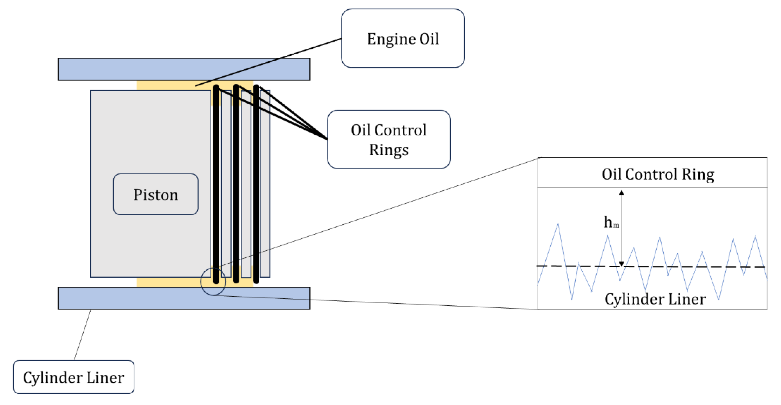
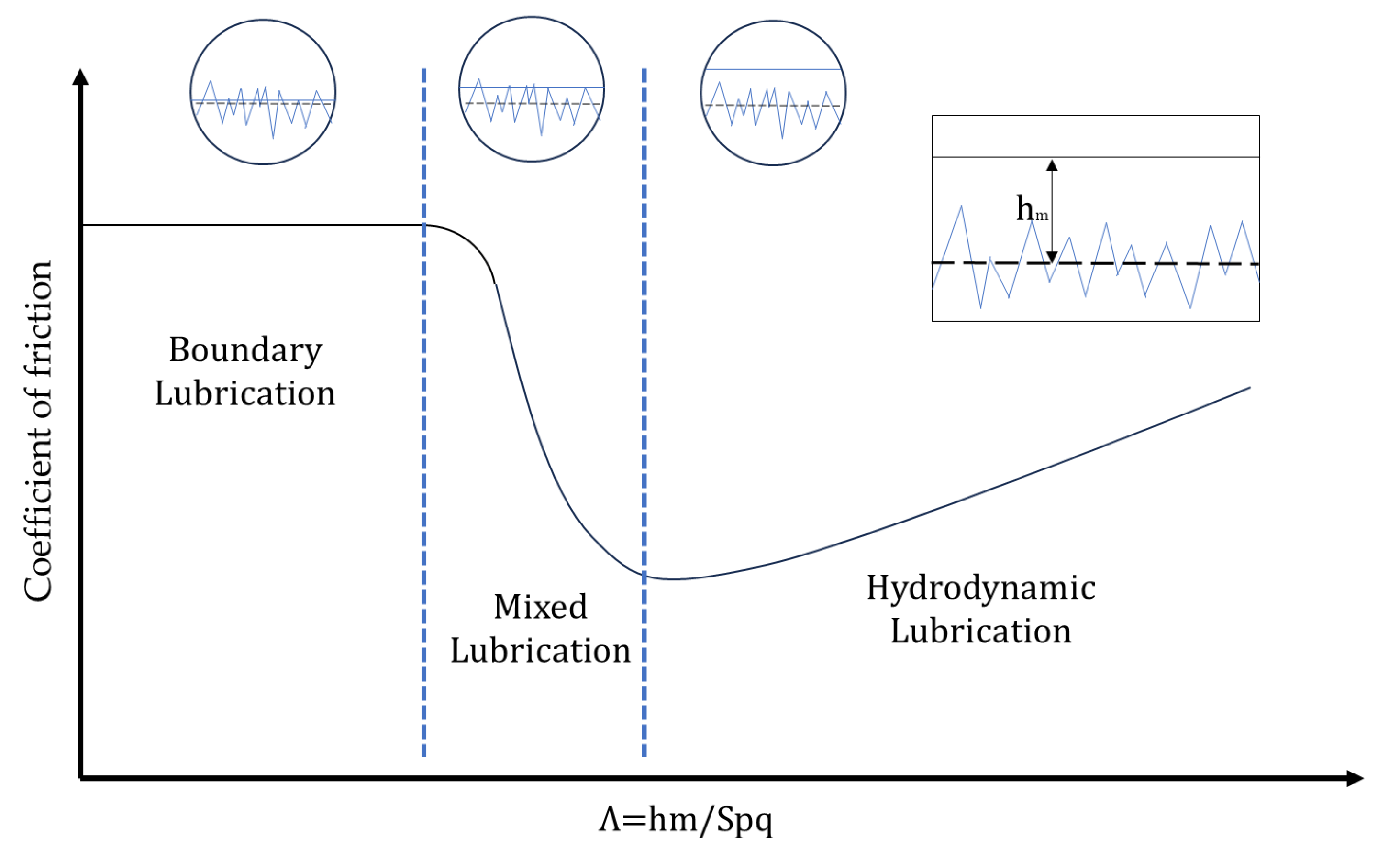
The reduction in frictional losses can be analyzed through the interaction of the tribological pair, namely the cylinder liner and the piston rings (see Figure 2). Approximately 50 to 75% of frictional losses occur at the interface between the piston rings and the cylinder liner surface [25]. The lubrication regimes (Figure 3) in the contact between the piston rings and the liner surface are (i) boundary lubrication at the top and bottom dead centers, characterized by significant asperity contact between the surfaces with little or almost no presence of lubricant; (ii) mixed lubrication regime, with reduced asperity contact and the presence of a lubricant film, that partially separates some of the surface asperities as the velocity increases; and (iii) hydrodynamic lubrication regime, with a full lubricant film separating the surfaces in the middle of the stroke (mid-stroke), distinguished by the absence of asperity contact and the formation of a complete film of lubricating oil [25]. In the piston-ring system, the most significant frictional forces are concentrated at the top and bottom dead center positions [26]. However, due to the low velocities at these positions, they account for only a minor fraction of the total frictional losses [27]. The majority of frictional power losses in internal combustion engines are situated within the hydrodynamic lubrication regime in the mid-stroke, where the piston reaches its maximum velocity, leading to increased shear forces in the lubricating oil and, thus, higher viscous losses [28].
The surface finish of piston cylinder liners significantly influences the friction coefficient, the load-carrying capacity between the tribological pair of cylinder liners and piston rings, and the durability of the sealing rings [29,30]. Plateau honing is a surface finishing process in cylinder liners that removes the highest peaks of the liner surface, resulting in a reduced surface roughness, imparting a surface texture characterized by deep valleys that serve as lubricant reservoirs [31,32]. In the mid-stroke, the hydrodynamic lubrication film generation can be facilitated by controlled cavitation within the valleys created by the honing grooves, effectively acting as micro-hydrodynamic bearings. Simultaneously, the relatively smooth plateau regions between the grooves are responsible for the robust load-carrying capacity.
While the honing process yields advantageous surface features for optimizing performance, recent studies have indicated that a combination of various texture levels can be particularly effective in reducing friction coefficient and wear. Of particular interest is the integration of honing textures with spherical pockets, commonly referred to as dimples. The behavior of the dimples is contingent upon their geometric attributes, including diameter, depth, and the density of the textured region [33]. Deep dimples, for instance, serve as reservoirs for lubricants, aiding in maintaining the lubricant film. Additionally, they can retain wear debris, thereby mitigating wear-related issues. In contrast, shallow dimples function as micro-hydrodynamic bearings, augmenting the film thickness and loading capacity while concurrently diminishing the coefficient of friction [34]. The combination of honing textures with dimples thus presents an intriguing avenue for further investigation, as it offers the potential to optimize surface performance through a tailored approach that considers the specific geometric properties of these dimples [25].
Numerical simulation is a powerful tool to help optimize the performance of textured surfaces in the ring/cylinder liner system, but it is very challenging due to the complexities involved [35]. In the mixed lubrication regime, the models should account for both lubrication and asperity contact [36,37].
Modeling the mixed lubrication behavior of piston ring/cylinder liner conjunctions involves describing the coupled effects of lubricant flow and asperity interactions [38,39]. These multiphysics phenomena can be considered using deterministic models that account for the whole surface topography [35,37,40] or averaging and homogenization models [41].
In this context, this study employs a deterministic numerical simulation approach to investigate various surface texturization parameters to optimize the tribological performance of textured liners for a free-piston linear engine. This investigation aims to assess the impact of surface textures on the friction behavior of the piston ring/cylinder liner conjunction, providing insights into potential strategies for enhancing engine performance that might enable the successful use of waste gas as fuel.

2. Deterministic Mixed Lubrication Model

Evaluating the frictional behavior of piston ring/cylinder liner systems across the various lubrication regimes necessitates a comprehensive approach and well-suited models. While acknowledging that several system properties can vary under real operating conditions, introducing effects such as temperature variation, system dynamics, mechanical deformation, or the influence of surface topography on frictional losses increases both the computational costs and the complexity of the simulation analysis. To address these difficulties while preserving the most significant mixed lubrication effects and the detailed influence of surface features in a computationally efficient simulation framework, the deterministic mixed lubrication model proposed by Profito, et al. [42] was used to investigate the lubrication performance of the textured liner. The model is based on the integrated solution of hydrodynamic and asperity contact problems in the same simulation framework using the full-scale representation of the cylinder liner topography.
The hydrodynamic pressure is calculated using the steady-state isothermal Reynolds equation with the Elrod–Adams pθ mass-conserving cavitation model, which can be written as follows [42]:
x ρ h 3 12 μ p h x + y ρ h 3 12 μ p h z = x ρ h U θ 2 ,
with the complementarity boundary conditions for cavitation [42]:
p h p c a v · 1 θ = 0       p h > p c a v , θ = 1 i n   D + p h = p c a v , 0 θ < 1 i n   D p h = p c a v , o n     C ,
In the above equations, p h is the hydrodynamic pressure, θ is the lubricant film fraction that represents the fluid saturation in the cavitation regions, ρ and μ are the lubricant density and viscosity, respectively, ℎ is the local lubricant gap that considers the full-scale geometric features of the surface topography, and U is the sliding velocity of the contacting surfaces. The liner surface was assumed to be rough and deformable, and the piston ring countersurface was admitted to be smooth, flat, and rigid. Furthermore, D + and D denote the pressured and cavitated regions, respectively, and C the cavitation boundaries. The hydrodynamic shear stress ( τ h ) in the sliding direction acting on the ring surface is calculated as follows [42]:
τ h = h 2 p h x + μ θ U h .
The mean contact pressure at each asperity of the rough liner surface interacting with the smooth rigid ring surface is calculated using an asperity-based elastic, perfectly plastic model based on Hertz’s theory for the contact between parabolical-shaped bodies. The surface hardness of the softer material is assumed to limit the plastic deformation in the contact zone. The expression of the mean contact pressure ( p a s p s ) for each asperity interaction is as follows [42]:
p a s p s = 4 E s * 3 π w s β s 1 2         , p a s p s H V             H V                         ,   p a s p s > H V   ,
where w s is the contact interference, β s is the local asperity radius of curvature, E s * is the combined elastic modulus of the asperity, and H V is the hardness of the softer material. β s is determined by approximating the geometry of each asperity with a best-fit parabolical cap using the neighboring points of the highest contact point; this allows for the contact pressure at each asperity to be distributed over the points that compound the asperity. The asperity contact shear stress ( τ a s p s ) is calculated based on the Coulomb–Amontons law for sliding friction, as follows [42]:
τ a s p s = μ B L p a s p s ,
where μ B L is the boundary friction coefficient usually determined experimentally.
In order to reduce the computational effort of the numerical solutions, the rough liner surface is segmented into slices of the same width as the smooth ring surface to emulate the ring contact area. For each slice, deterministic simulations are performed for a constant lubricant viscosity and sliding velocity and a range of imposed separations ( h m ) between the rigid surface and the reference plane of the rough surface (see more details in Section 3.1). Subsequently, the governing equations of the hydrodynamic and asperity contact problems described above are solved quasi-statically for each imposed separation. The pθ Reynolds equation (Equations (1) and (2)) is solved numerically using the hybrid-type Element-based Finite Volume Method (EbFVM) proposed by Profito, Giacopini, Zachariadis and Dini [42] to solve lubrication problems, automatically ensuring mass conservation even in conditions with inter-asperity cavitation, as are the cases investigated in this work.
The deterministic simulations provide the distributions of the hydrodynamic pressure, hydrodynamic shear stress, asperity contact pressure, and asperity shear stress for each surface slice and imposed separations. In many situations, it is convenient to evaluate the global effect of these field results as a function of the dimensionless film thickness Λ = h m / S p q using the following average quantities:
P h Λ = 1 N i = 1 N p h i ,                 τ ¯ h Λ = 1 N i = 1 N τ h i , P a s p Λ = 1 N i = 1 N p a s p i ,                 τ ¯ a s p Λ = 1 N i = 1 N τ a s p i ,               C O F Λ = τ ¯ h Λ + τ ¯ a s p Λ P h Λ + P a s p Λ ,
where N is the number of mesh points of each surface slice, and P h , τ ¯ h , P a s p , τ ¯ a s p , and C O F are the average hydrodynamic pressure, hydrodynamic shear stress, asperity contact pressure, asperity contact shear stress and coefficient of friction, respectively.

3. Methodology

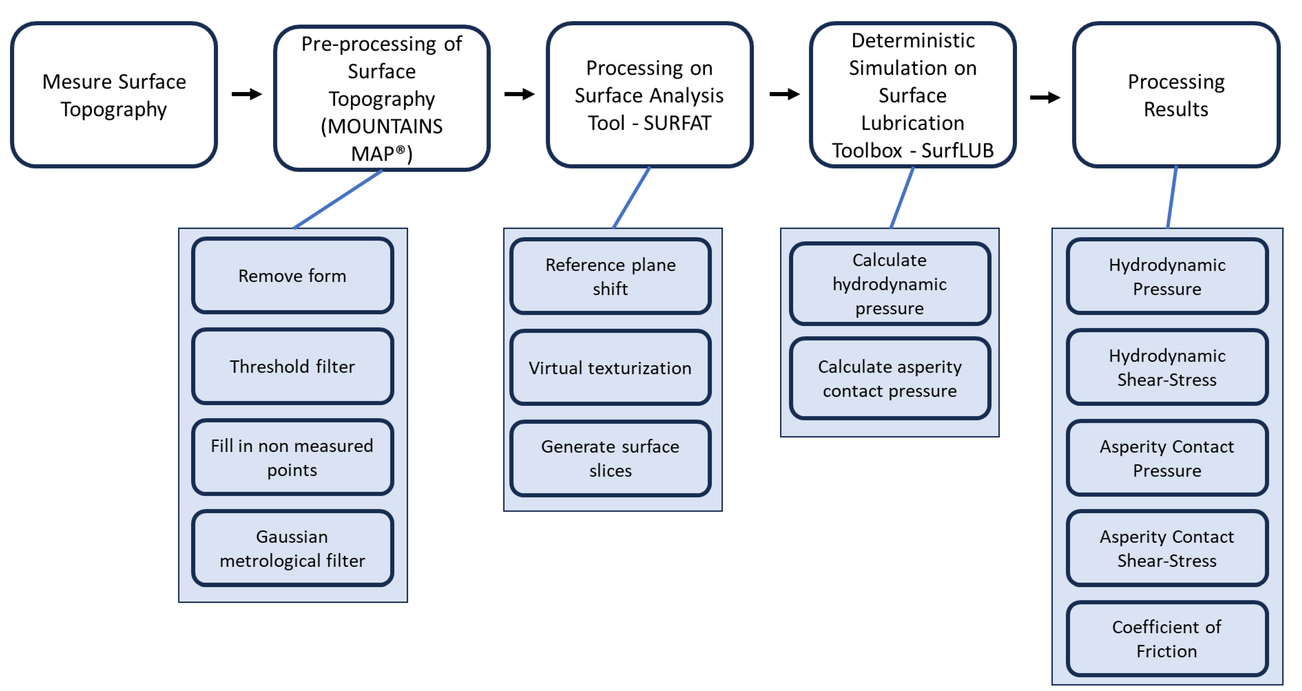
The analysis process is summarized via the flowchart in Figure 4, outlining each sequential step and its key attributes. The analysis begins with measurements of surface topography, followed by adjustments to isolate the impact of surface roughness and texture. The subsequent stages highlight how the proposed surface textures influence the system lubrication performance using the results obtained with the deterministic mixed lubrication model.

3.1. Surface Processing

The surfaces of commercial grey cast iron honed liner samples were measured using a Taylor Robson CCI laser interferometer. These measurements employed the stitching technique, allowing for the sampling of a large area.
The measured surfaces were initially processed using the MounstainsMap® Imaging Topography software version 9.0 from DigitalSurf. The treatment of the surfaces involved the following steps: (i) surface levelling; (ii) form removal, using a third-degree polynomial fitting; (ii) application of a threshold to remove measurement outliers, eliminating surface height data that fell outside the range of 0.20% to 99.80% according to the Abbot–Firestone curve; (iii) filling in non-measured points; and (iv) application of a robust Gaussian metrological filter with a cut-off of 800 μm to separate surface roughness and waviness.
The surface topography data were subsequently processed using the in-house Matlab toolbox SURFAT (‘Surface Analysis Toolbox’) to prepare the surface topographies for the numerical simulations. SURFAT is a general-purpose surface analysis toolbox developed at the Laboratory of Surface Phenomena (LFS) of the University of São Paulo (USP). SURFAT divided the rough liner surfaces into slices to facilitate data processing and reduce the computational cost of the numerical simulations. Each slice has the same width of the ring face (1000 μm in this work) to reproduce the ring contact area on the liner. An overlap of 50 μm was applied to emulate the ring’s sliding motion effect along the stroke, resulting in 97 slices. A computational mesh of 376 × 251 was used to discretize each slice for the numerical simulations.
The honing grooves and surface textures cause a shift in the position of the reference plane of featured surfaces, which no longer coincides with the plateau region, where the actual contact takes place. A plateau segmentation method based on the Gaussian Mixture Model clustering method was used to overcome such reference plane shift, as illustrated in the Results section. This correction, proposed in a recent work, considers the roughness of the plateau region for adjusting the location of the reference plane. This adjustment is necessary because the surface separations and the lubricating film thickness are defined in the numerical model from the reference plane of the plateau, which is more convenient for mixed lubrication analysis [43].
Within the SURFAT program, a MATLAB code extension was developed to create virtual texturing so that spherical dimples could be added to measured surfaces of the commercial honed liners. The input parameters for creating the dimples include the dimple radius (Dr), the distance between the centers of the dimples (Ds), and the ratio between the dimple’s depth and radius (Dd). Surfaces with different textured area densities were generated using the parameters shown in Table 1 for numerical simulations. These virtual surfaces enabled the assessment of the impact of textured area density on the surface properties and lubrication performance, which are crucial for optimizing tribological systems.
The simulations were conducted using the in-house computational code SURFLUB (SURFace LUBrication), which solves the governing equations of the deterministic mixed lubrication model described in Section 2. SURFLUB was also developed at the Laboratory of Surface Phenomena (LFS) of the University of São Paulo (USP). The analysis involved the imposition of different lambda ratios (Λ = hm/Spq) under steady-state conditions, where hm is the imposed separation between the reference plane of the piston liner surface roughness and the smooth and rigid theorical surface of the piston’s oil control ring, and Spq is the standard deviation of the roughness in the plateau region of the cylinder liner surface. The variation in the imposed Λ values aimed to use a larger number of points in the regions of thinner films, as described in Table 2, where the variation step increases as the imposed film becomes thicker.
The lubricant properties were selected for a commercial SAE 30 oil. The mechanical properties of the contacting materials were obtained from the literature. All other relevant parameters for the numerical simulations are summarized in Table 3.

3.2. Outlier Removal

A post-processing treatment was applied to the averaged simulation results (see Section 2) to remove outliers using Tukey’s method. The detection and removal of outliers are crucial procedures in statistical data analysis. Tukey’s method provides an effective approach to identifying and addressing these extreme observations, beginning by calculating the Interquartile Range (IQR) of the dataset. The IQR is the difference between the third quartile (Q3) and the first quartile (Q1): IQR = Q3 − Q1. Next, the upper and lower limits are established to identify outliers. These limits are typically determined as follows: lower limit: calculated as Q1 − 1.5 × IQR; upper limit: calculated as Q3 + 1.5 × IQR; values that fall below the lower limit or above the upper limit are considered outliers. Once the limits are defined, it is possible to identify and, if necessary, remove outliers from the dataset [44].

4. Results and Discussion

4.1. Original Surface Processing

The results of the original surface pre-processing are shown in Figure 5, where level, form and waviness have been adequately removed. This step is fundamental to ensure that only the effect of the surface roughness is accounted for in the numerical simulations. The surface roughness parameters calculated after the pre-processing are summarized in Table 4. These parameters are widely used for the statistical characterization of the surface topography of cylinder liners [31] and are defined by the standard ISO 25178-2 [45]. As the surface of the ring is assumed to be smooth and rigid in the numerical model, only the liner topography is considered during surface processing. As defined in Section 2, the standard deviation of the plateau roughness, Spq, is used to calculate the dimensionless separation ( Λ ) between the surfaces.
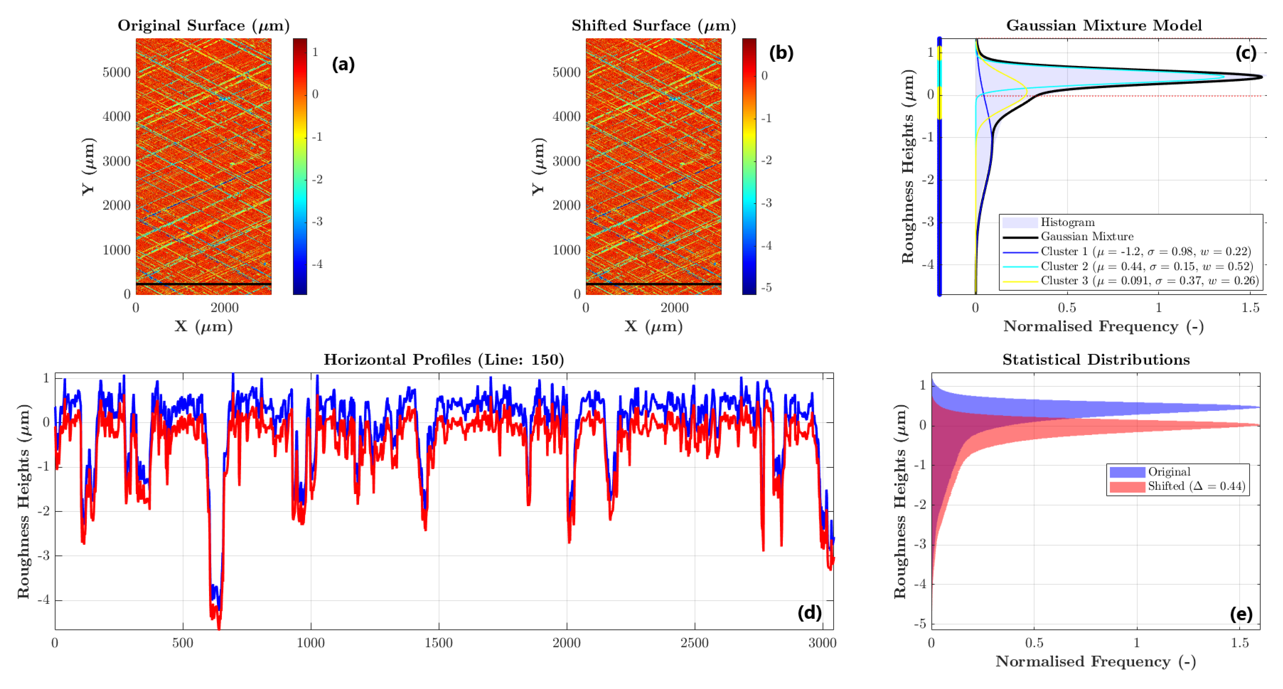
The preparation for the numerical simulation of the surface topography uses the Gaussian Mixture Model method to identify clusters in the height distributions (Figure 6c). The mean height of the cluster with the highest frequency is used to shift the reference plane to the plateau to compensate for its deviation caused by the honed grooves (Figure 6e). This shift in the reference plane is exemplified by the selected profiles shown in Figure 6d, where blue is the profile of the original surface, and red is the profile of the shifted surface.
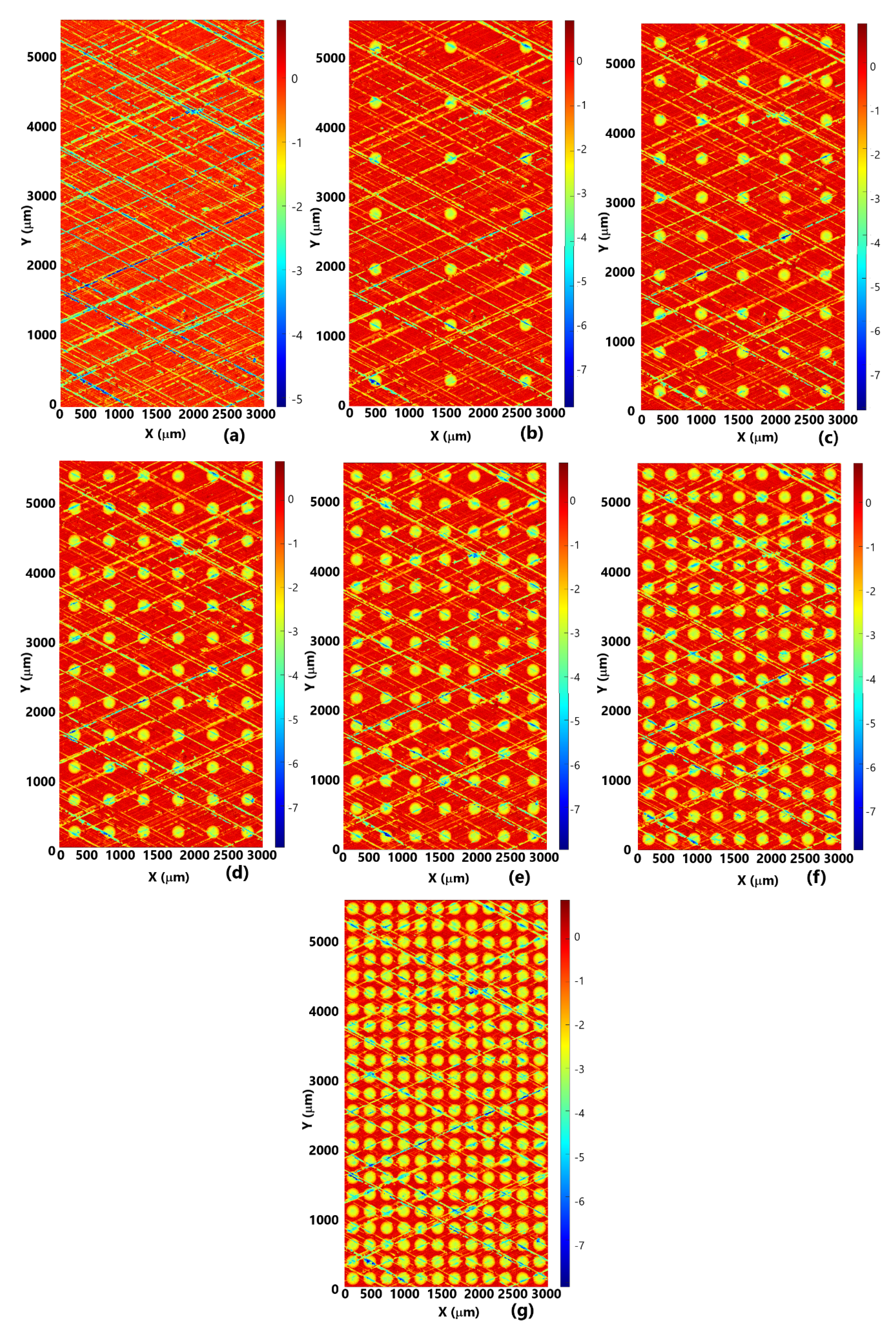
After shifting the reference plane, virtual texturing was applied to the original surface, resulting in the textured surfaces shown in Figure 7. The virtual texturing of the pre-processed surface does not change the position of the reference plane.

4.2. Field Results

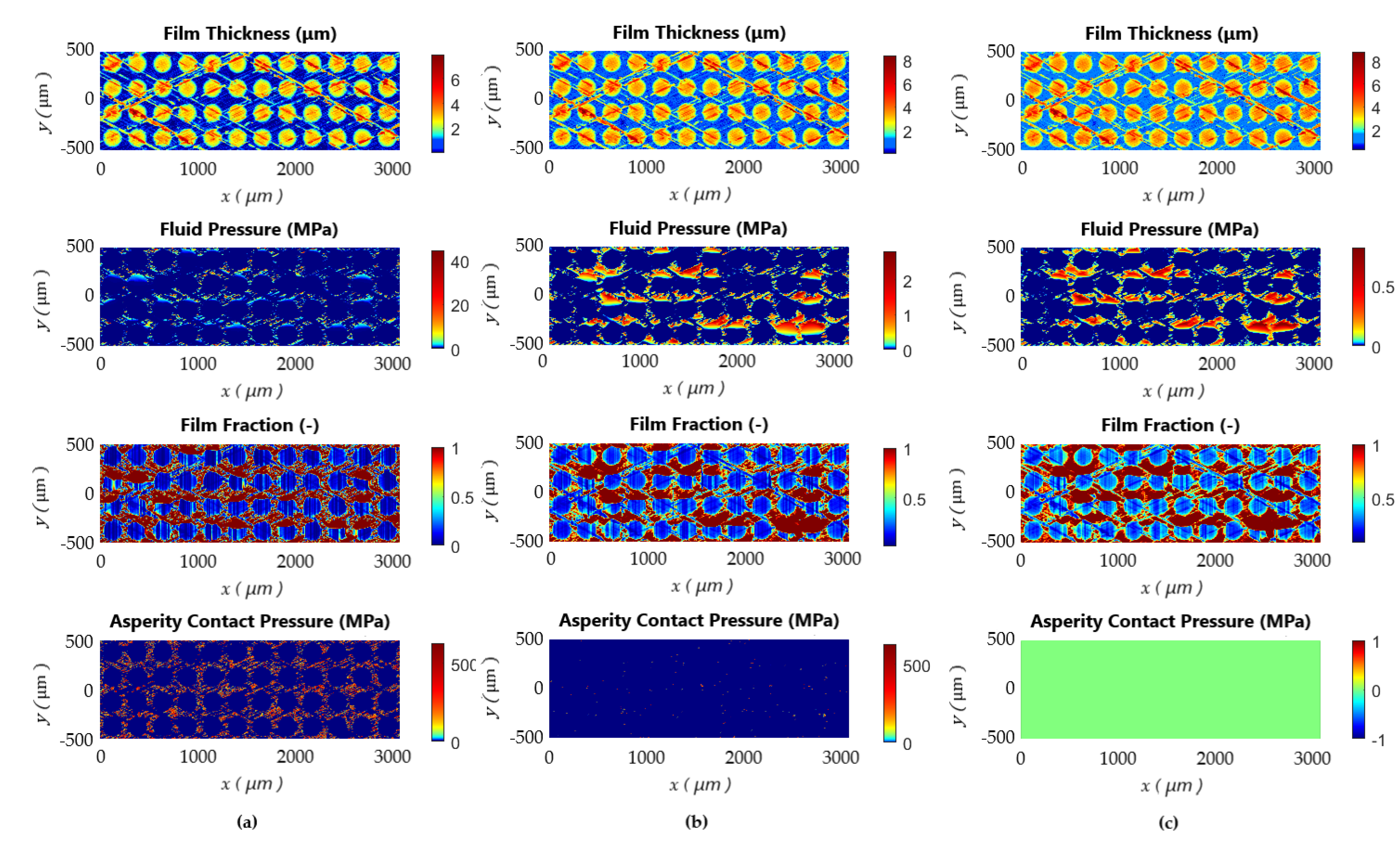
Representative examples of the film thickness, hydrodynamic pressure, film fraction (cavitation), and contact pressure distributions are depicted in Figure 8 and Figure 9 for the first slices of the original and textured (50%) surfaces, respectively. Similar field results for textured surfaces with all the area coverages can be found in the Supplementary Materials Figure S1. In all these figures, (a) corresponds to the dimensionless separation Λ = 0.5, (b) Λ = 2.5, and (c) Λ = 4.5. Therefore, the selected field results relate to distinct lubrication regimes, enabling a comprehensive evaluation of the surface texture behavior across the boundary, mixed, and hydrodynamic lubrication regimes.

4.3. Average Results

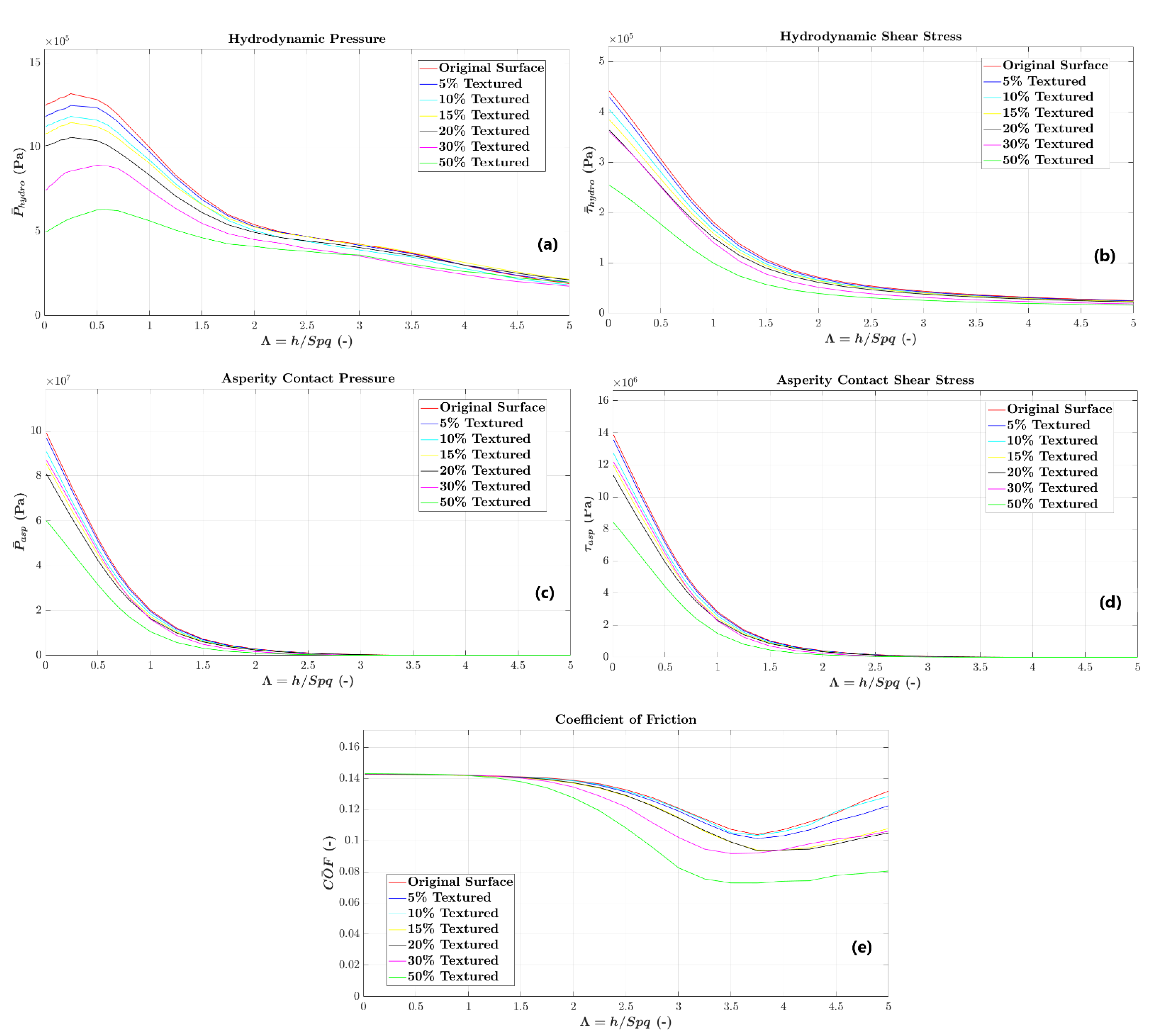
The average results of the numerical simulations allow for an overall performance comparison of the evaluated topographies in terms of hydrodynamic pressure support (Figure 10a) and shear stress (Figure 10b), as well as regarding the asperities contact pressure (Figure 10c), shear stress (Figure 10d) and total coefficient of friction (Figure 10e).
As the percentage of the textured area increases, a discernible decrease in hydrodynamic pressure is evident, as depicted in Figure 10a, specifically within the dimensionless film thickness associated with the boundary lubrication regime. An analysis of the fluid pressure field results in Figure 8 and Figure 9 reveals near-zero pressure on the dimples despite the presence of cavitated fluid, as indicated by the film fraction field results. Notably, the cavitated fluid does not contribute to a significant micro-hydrodynamic bearing effect capable of elevating fluid pressure on the plateau regions.
This observed behavior persists across varying percentages of textured areas, with the 50% textured area displaying the lowest hydrodynamic pressure within the boundary lubrication regime. As the transition to the mixed and hydrodynamic lubrication regime occurs, the hydrodynamic pressure curves begin to converge.
Despite the heightened presence of fluid associated with larger percentages of textured areas, a noteworthy reduction in hydrodynamic shear stress is observed in the boundary and mixed lubrication regimes, as illustrated in Figure 10b. This reduction is attributed to a simultaneous decrease in the fluid shear rate over the textures and in the effective viscosity due to the texture-induced cavitation, as discerned from both the hydrodynamic shear stress data and the field results for film fraction. Equation (3) underscores the impact of the local film thickness (h) and film fraction (θ) on the hydrodynamic shear stress, offering insights into the observed decrease in these results.
The predicted reductions in asperity contact pressure (Figure 10c) and shear stress (Figure 10d) resulted from a diminished real contact area due to increased textured area percentages, as can be observed with the diminishing upper support coverage parameters in Table 3 for the Smrk2 parameter with the increase in textured area coverage. Despite this, it is essential to note that in the deterministic model employed, the boundary friction coefficient was imposed as 0.14 (Table 3), leading to the convergence of the predicted coefficient of friction (Figure 10e) for all textured area percentages for the dimensionless film thickness associated with the boundary lubrication regime.
The curves representing the coefficient of friction (Figure 10e) exhibit a notable leftward shift for the transition point from the boundary to the mixed lubrication regime as the textured area percentage increased, with the 50% textured area percentage entering the mixed lubrication regime for the lowest Λ values. Furthermore, as the textured area increased, there was a reduction in the increase rate for the coefficient of friction during the hydrodynamic lubrication regime.
Surface textures with 5% and 10% textured area percentages displayed remarkably similar behavior across all three lubrication regimes, as did surfaces with 15% and 20% textured area percentages. This trend suggests a consistent response among these specific textured area percentages, highlighting their comparable performance throughout different lubrication conditions.
The field results in Figure 8 and Figure 9 show the roughness and texture-induced hydrodynamic pressure generation, especially near the honed grooves and dimples. Furthermore, the influence of inter-asperity cavitation (fluid fraction field) within the honed grooves and textures on the local lubricant flow and its impact on the fluid pressure buildup is noticeable.
Analyzing the field results for Λ = 0.5 (boundary lubrication regime), spikes in fluid pressure are evident. However, while the hydrodynamic pressure is high at some localized points, an insufficient amount of fluid limits its significant influence on the overall coefficient of friction across all surface topographies. Furthermore, as expected for this lubrication regime, most frictional losses originate from the asperity interactions [46].
The contact between surfaces diminishes in the mixed lubrication regime (Λ = 2.5), and the lubricant can flow more easily through the interface. Therefore, the hydrodynamic micro-bearing effect starts increasing the pressure on the plateau region. In the honing grooves and inside dimples, the cavitated fluid pushes out, elevating the pressure on the plateau downstream of the convergent portions of the surface features [47]. Furthermore, the surface topographies with increased area coverage yielded lower friction due to reduced contact and hydrodynamic shear stress over the dimples.
In the hydrodynamic lubrication regime, the contact effect of surface asperities is eliminated, as shown in the contact pressure distributions for all simulated surface topographies for Λ = 4.5. The film fraction parameter also indicates the integrity of the lubricant film in the plateau region. The increase in the area coverage of the textures directly reduces fluid pressure due to decreased plateau areas. A larger textured area reduces plateau regions with increased pressure from the hydrodynamic bearing effect, lowering the average hydrodynamic pressure, as shown in Figure 6. The global friction coefficient followed a similar trend to the mixed lubrication regime for all simulated surface topographies, with friction decrease now solely governed by the hydrodynamic shear stress reduction mechanism.
The rise in void volume (Vv) due to an increased textured area signifies an augmented capacity for lubricant storage in surface topography, helping to maintain the lubricant film. Despite the larger amount of lubricant due to textures, there is a reduction in hydrodynamic shear stress across all lubrication regimes with increased area coverage. Furthermore, the increase in the area coverage of the textures influences the transition point from the boundary to the mixed lubrication regime (see Figure 10) and significantly reduces the coefficient of friction in both mixed and hydrodynamic lubrication regimes. The combination of reduced plateau contact area and increased void volume significantly impacts the global coefficient of friction, with the textured surface with 50% area coverage demonstrating the best performance.

5. Conclusions

This work used a deterministic mixed lubrication model to evaluate the frictional behavior across diverse lubrication regimes for the proposed surface textures. The results underscore the advantageous impact of the hydrodynamic bearing effect induced by fluid cavitation within surface features, leading to a notable reduction in the global coefficient of friction as the textured area increases.
Remarkably, the surface with a 50% textured area exhibited optimal performance, enabling its transition into the mixed lubrication regime with a lower film thickness (Λ) than other surface textures. In the hydrodynamic lubrication regime, this surface demonstrated a marginal increase in the global coefficient of friction compared to the other surface topographies.
These findings provide valuable insights for optimizing tribological performance, highlighting the pivotal role of surface topography in influencing lubrication regimes and frictional behavior across a broad spectrum of engineering applications.

Supplementary Materials

The following supporting information can be downloaded at: https://www.mdpi.com/article/10.3390/lubricants12010012/s1, Figure S1: Field results at different Λ ratios for textured surfaces with textured area coverages varying from 5% to 30%.

Author Contributions

Conceptualization, H.L.C. and M.B.d.S.; methodology, F.J.P.; software, F.J.P., S.A.N.S. and F.K.C.L.; formal analysis, H.L.C. and F.J.P.; investigation, F.K.C.L.; resources, M.B.d.S. and H.L.C.; writing—original draft preparation, F.K.C.L.; writing—review and editing, H.L.C. and F.J.P.; visualization, F.K.C.L. and S.A.N.S.; supervision, H.L.C.; project administration, M.B.d.S.; funding acquisition, M.B.d.S. and H.L.C. All authors have read and agreed to the published version of the manuscript.

Funding

The authors would like to thank FINEP for funding project 01.21.0144.00 (0751/21). HLC acknowledges financial support from CNPq (project 305453/2017-3), as well as CNPq/INCT CT Trib (project 406654/2022-0).

Data Availability Statement

Original data can become available upon request directly to the authors.

Conflicts of Interest

The authors declare no conflicts of interest. The funders had no role in the design of the study; in the collection, analyses, or interpretation of data; in the writing of the manuscript, or in the decision to publish the results.

References

  1. Almohaimeed, S.A.; Suryanarayanan, S.; O’Neill, P. Reducing carbon dioxide emissions from electricity sector using demand side management. Energy Sources Part A-Recovery Util. Environ. Eff. 2021, 1–21. [Google Scholar] [CrossRef]
  2. Moreira, H.C.R.; Oliveira, J.A.B.; Carreño, N.L.V.; Silva, R.; Garcia, I.T.S.; Costa, H.L.; Alano, J.H. Effects of niobium pentoxide nanoparticles on the tribological properties of electrodeposited ZnNi coatings. Surf. Topogr.-Metrol. Prop. 2022, 10, 024003. [Google Scholar] [CrossRef]
  3. Cesur, I.; Akgündüz, M.; Çelik, H.A.; Çay, Y.; Ergen, G. Tribological Analysis and Optimization of Ring-Cylinder Couple Coated with Different Materials. Arab. J. Sci. Eng. 2023, 1–12. [Google Scholar] [CrossRef]
  4. Prajapati, D.K.; Ahmad, D.; Katiyar, J.K.; Prakash, C.; Ajaj, R.M. A numerical study on the impact of lubricant rheology and surface topography on heavily loaded non-conformal contacts. Surf. Topogr.-Metrol. Prop. 2023, 11, 035006. [Google Scholar] [CrossRef]
  5. Hei, D.; Zheng, M.R.; Liu, C.; Jiang, L.T.; Zhang, Y.F.; Zhao, X.W. Study on the frictional properties of the top ring-liner conjunction for different-viscosity lubricant. Adv. Mech. Eng. 2023, 15, 16878132231155002. [Google Scholar] [CrossRef]
  6. Rodrigues, T.A.; Arencibia, R.V.; Costa, H.L.; da Silva, W.M. Roughness analysis of electrochemically textured surfaces: Effects on friction and wear of lubricated contacts. Surf. Topogr.-Metrol. Prop. 2020, 8, 024011. [Google Scholar] [CrossRef]
  7. Atulkar, A.; Pandey, R.K.; Subbarao, P.M.V. Synergistic effect of textured piston ring and nano-lubricant on performance parameters and emissions of IC engine. Surf. Topogr.-Metrol. Prop. 2021, 9, 035009. [Google Scholar] [CrossRef]
  8. Mohammadpour, M.; Morris, N.J.; Leighton, M.; Rahnejat, H. Effect of surface topography upon micro-impact dynamics. Surf. Topogr.-Metrol. Prop. 2016, 4, 014001. [Google Scholar] [CrossRef]
  9. Costa, H.L.; Cousseau, T.; Souza, R.M. Current Knowledge on Friction, Lubrication, and Wear of Ethanol-Fuelled Engines-A Review. Lubricants 2023, 11, 292. [Google Scholar] [CrossRef]
  10. Udeagha, M.C.; Ngepah, N. Striving towards carbon neutrality target in BRICS economies: Assessing the implications of composite risk index, green innovation, and environmental policy stringency. Sustain. Environ. 2023, 9, 2210950. [Google Scholar] [CrossRef]
  11. Kime, S.; Jacome, V.; Pellow, D.; Deshmukh, R. Evaluating equity and justice in low-carbon energy transitions. Environ. Res. Lett. 2023, 18, 123003. [Google Scholar] [CrossRef]
  12. Zheng, J.J.; Impeng, S.; Liu, J.; Deng, J.; Zhang, D.S. Mo promoting Ni-based catalysts confined by halloysite nanotubes for dry reforming of methane: Insight of coking and H2S poisoning resistance. Appl. Catal. B-Environ. Energy 2024, 342, 123369. [Google Scholar] [CrossRef]
  13. Pawananont, K.; Leephakpreeda, T. Experimental investigation and optimal combustion control of untreated landfill gas via fuzzy logic rule knowledge based approach. Waste Manag. 2021, 121, 383–392. [Google Scholar] [CrossRef] [PubMed]
  14. Zhang, X.Y.; Khandavilli, M.; Gautam, R.; Alabbad, M.; Li, Y.; Chatakonda, O.; Kloosterman, J.W.; Middaugh, J.; Sarathy, S.M. An updated functional-group-based approach to modeling the vacuum residue oil gasification kinetics. Fuel 2024, 357, 129759. [Google Scholar] [CrossRef]
  15. Tsipis, E.V.; Matveev, D.V.; Sharafutdinov, A.U.; Yalovenko, D.V.; Samoilov, A.V.; Fedotov, Y.S.; Dyakina, M.S.; Zhigacheva, D.V.; Agarkov, D.A.; Bredikhin, S.I.; et al. Performance of SOFCs using model waste gases: A case study. Fuel 2024, 358, 130129. [Google Scholar] [CrossRef]
  16. Xu, S.Y.; Nguyen, V.; Wang, X.J.; Zhou, H.X. Sensitivity Analysis of the Geometrical Dimensions of the Crankpin Bearing on the Tribological Property of an Engine. Sae Int. J. Engines 2022, 15, 367–380. [Google Scholar] [CrossRef]
  17. Yang, F.Y.; Feng, H.H.; Wu, L.M.; Zhang, Z.Y.; Wang, J.Y. Performance prediction and parameters optimization of an opposed-piston free piston engine generator using response surface methodology. Energy Convers. Manag. 2023, 295, 117633. [Google Scholar] [CrossRef]
  18. Hung, N.B.; Lim, O. A review of free-piston linear engines. Appl. Energy 2016, 178, 78–97. [Google Scholar] [CrossRef]
  19. Wu, J.P.; Nicholas, P.; Peter Van, B.; Goldborough, S. Homogeneous Charge Compression Ignition Free Piston Linear Alternator; University of North Texas Libraries, UNT Digital Library: Denton, TX, USA, 1998. [Google Scholar]
  20. Guo, C.D.; Zuo, Z.X.; Feng, H.H.; Roskilly, T. Advances in free-piston internal combustion engines: A comprehensive review. Appl. Therm. Eng. 2021, 189, 116679. [Google Scholar] [CrossRef]
  21. Guo, C.D.; Wang, Y.H.; Tong, L.; Feng, H.H.; Zuo, Z.X.; Jia, B.R. Research on Piston Dynamics and Engine Performances of a Free-Piston Engine Linear Generator Coupling with Various Rebound Devices. Energies 2023, 16, 6570. [Google Scholar] [CrossRef]
  22. Holmberg, K.; Andersson, P.; Erdemir, A. Global energy consumption due to friction in passenger cars. Tribol. Int. 2012, 47, 221–234. [Google Scholar] [CrossRef]
  23. Atulkar, A.; Pandey, R.K.; Subbarao, P.M.V. Role of textured piston rings/liners in improving the performance behaviours of IC engines: A review with vital findings. Surf. Topogr.-Metrol. Prop. 2021, 9, 023002. [Google Scholar] [CrossRef]
  24. Li, S.J.; Wu, Z.P.; Dong, B.W.; Luo, W.Y.; Song, H.L.; Guo, H.T.; Zhou, A.Q. Improvement of lubrication performance of sliding pairs with multi-depth groove textures based on genetic algorithm. Surf. Topogr.-Metrol. Prop. 2023, 11, 025011. [Google Scholar] [CrossRef]
  25. Wakuri, Y.; Hamatake, T.; Soejima, M.; Kitahara, T. Piston ring friction in internal combustion engines. Tribol. Int. 1992, 25, 299–308. [Google Scholar] [CrossRef]
  26. dos Santos Filho, D.; Tschiptschin, A.P.; Goldenstein, H. Effects of ethanol content on cast iron cylinder wear in a flex-fuel internal combustion engine–A case study. Wear 2018, 406–407, 105–117. [Google Scholar] [CrossRef]
  27. Morris, N.; Rahmani, R.; Rahnejat, H.; King, P.D.; Howell-Smith, S. A Numerical Model to Study the Role of Surface Textures at Top Dead Center Reversal in the Piston Ring to Cylinder Liner Contact. J. Tribol.-Trans. Asme 2016, 138, 021703. [Google Scholar] [CrossRef]
  28. Johansson, S.; Nilsson, P.H.; Ohlsson, R.; Rosén, B.-G. A Novel Approach to Reduction of Frictional Losses in a Heavy-Duty Diesel Engine by Reducing the Hydrodynamic Frictional Losses. Adv. Tribol. 2017, 2017, 1–17. [Google Scholar] [CrossRef]
  29. Miao, C.W.; Guo, Z.W.; Yuan, C.Q. An experimental study on tribological properties and air tightness of co-textured cylinder liner-piston ring on an engine tester. Surf. Topogr.-Metrol. Prop. 2021, 9, 015005. [Google Scholar] [CrossRef]
  30. Leighton, M.; Rahmani, R.; Rahnejat, H. Surface-specific flow factors for prediction of friction of cross-hatched surfaces. Surf. Topogr.-Metrol. Prop. 2016, 4, 025002. [Google Scholar] [CrossRef]
  31. Pawlus, P.; Reizer, R. Functional importance of honed cylinder liner surface texture: A review. Tribol. Int. 2022, 167, 107409. [Google Scholar] [CrossRef]
  32. Reizer, R.; Pawlus, P.; Wieczorowski, M. Simulation of plateau-honed cylinder liner surface texture creation using superimposition approach. Precis. Eng.-J. Int. Soc. Precis. Eng. Nanotechnol. 2023, 82, 10–24. [Google Scholar] [CrossRef]
  33. Lu, P.; Wood, R.J.K. Tribological performance of surface texturing in mechanical applications—A review. Surf. Topogr.-Metrol. Prop. 2020, 8, 043001. [Google Scholar] [CrossRef]
  34. Rosenkranz, A.; Szurdak, A.; Gachot, C.; Hirt, G.; Mücklich, F. Friction reduction under mixed and full film EHL induced by hot micro-coined surface patterns. Tribol. Int. 2016, in press. [Google Scholar] [CrossRef]
  35. Liao, K.; Liu, Y.; Kim, D.; Urzua, P.; Tian, T. Practical challenges in determining piston ring friction. Proc. Inst. Mech. Eng. Part J J. Eng. Tribol. 2012, 227, 112–125. [Google Scholar] [CrossRef]
  36. Chu, N.R.; Jackson, R.L.; Ghaednia, H.; Gangopadhyay, A. A Mixed Lubrication Model of Piston Rings on Cylinder Liner Contacts Considering Temperature-Dependent Shear Thinning and Elastic-Plastic Contact. Lubricants 2023, 11, 208. [Google Scholar] [CrossRef]
  37. Chen, H.; Liao, K.; Tian, T. A Numerical and Experimental Study of Twin-land Oil Control Ring Friction in Internal Combustion Engines Part 2. SAE Int. J. Engines 2012. [Google Scholar] [CrossRef]
  38. Tomanik, E. Modelling the hydrodynamic support of cylinder bore and piston rings with laser textured surfaces. Tribol. Int. 2013, 59, 90–96. [Google Scholar] [CrossRef]
  39. Profito, F.J.; Tomanik, E.; Zachariadis, D.C. Effect of cylinder liner wear on the mixed lubrication regime of TLOCRs. Tribol. Int. 2016, 93, 723–732. [Google Scholar] [CrossRef]
  40. Liu, Y.; Li, Y.; Tian, T. Development and Application of Ring-Pack Model Integrating Global and Local Processes. Part 2: Ring-Liner Lubrication. SAE Int. J. Engines 2017, 10, 1969–1983. [Google Scholar] [CrossRef]
  41. Söderfjäll, M.; Almqvist, A.; Larsson, R. A model for twin land oil control rings. Tribol. Int. 2016, 95, 475–482. [Google Scholar] [CrossRef]
  42. Profito, F.J.; Giacopini, M.; Zachariadis, D.C.; Dini, D. A General Finite Volume Method for the Solution of the Reynolds Lubrication Equation with a Mass-Conserving Cavitation Model. Tribol. Lett. 2015, 60, 18. [Google Scholar] [CrossRef]
  43. Silva, S.A.N. A Comparison of Texturized Surfaces for Ring-Cylinder through Deterministic Simulation. Master’s Thesis, Universidade Federal de Uberlândia, Uberlândia, Brazil, 2022. [Google Scholar]
  44. Schwertman, N.C.; Owens, M.A.; Adnan, R. A simple more general boxplot method for identifying outliers. Comput. Stat. Data Anal. 2004, 47, 165–174. [Google Scholar] [CrossRef]
  45. ISO-25178-2; Geometrical Product Specifications (GPS): Surface Texture: Areal—Part 2: Terms, Definitions and Surface Texture Parameters. ISO: Geneva, Switzerland, 2021.
  46. Scaraggi, M.; Mezzapesa, F.P.; Carbone, G.; Ancona, A.; Tricarico, L. Friction Properties of Lubricated Laser-MicroTextured-Surfaces: An Experimental Study from Boundary- to Hydrodynamic-Lubrication. Tribol. Lett. 2013, 49, 117–125. [Google Scholar] [CrossRef]
  47. Vlădescu, S.-C.; Olver, A.V.; Pegg, I.G.; Reddyhoff, T. Combined friction and wear reduction in a reciprocating contact through laser surface texturing. Wear 2016, 358–359, 51–61. [Google Scholar] [CrossRef]
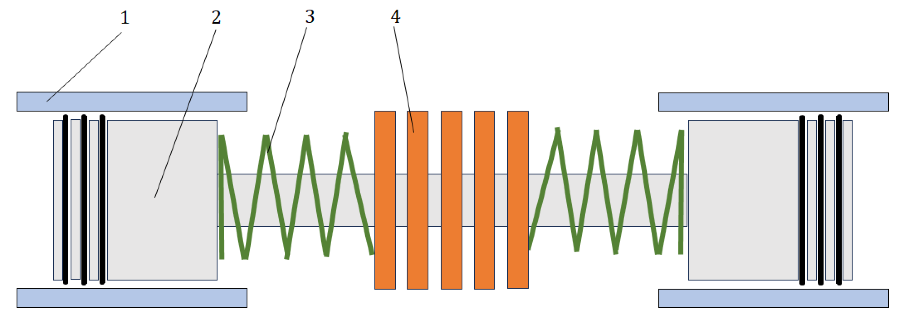
Figure 1. Schematics of a free-piston linear engine with opposed pistons. 1—cylinder liner; 2—piston; 3—springs; 4—stator.
Lubricants 12 00012 g001
Figure 2. Schematics of the interaction between the cylinder liner and the piston rings.
Lubricants 12 00012 g002
Figure 3. Stribeck curve describing the correlation between the coefficient of friction and the dimensionless film thickness or lambda ratio ( Λ = h m / S p q ).
Lubricants 12 00012 g003
Figure 4. Flowchart of the methodology applied in the conducted analysis.
Lubricants 12 00012 g004
Figure 5. Cylinder liner topography; (a) 3D representation of the surface roughness; (b) 2D representation of the surface roughness.
Lubricants 12 00012 g005
Figure 6. Mean plane shift using a Gaussian Mixture Model: (a) top view of the original surface; (b) top view of the shifted original surface; (c) Gaussian Mixture Model used for surface clustering; (d) line profiles comparing original (blue) and shifted condition (red); (e) comparison of height asperity distributions of the original and shifted surfaces.
Lubricants 12 00012 g006
Figure 7. Surfaces for the numerical simulations with different area coverage percentages of the textures: (a) original surface; (b) 5%; (c) 10%; (d) 15%; (e) 20%; (f) 30%; (g) 50%.
Lubricants 12 00012 g007
Figure 8. Field results of the original surface for: (a) Λ = 0.5; (b) Λ = 2.5; and (c) Λ = 4.5.
Lubricants 12 00012 g008
Figure 9. Field results of the textured surface (50%) for: (a) Λ = 0.5; (b) Λ = 2.5; and (c) Λ = 4.5.
Lubricants 12 00012 g009
Figure 10. Average results of the deterministic simulations: (a) hydrodynamic pressure; (b) hydrodynamic shear stress; (c) asperity contact pressure; (d) asperity contact shear stress; (e) coefficient of friction.
Lubricants 12 00012 g010
Table 1. Virtual texturing parameters.
Coverage Area PercentageDr (μm)Ds (μm)Dd
Original Untextured Surface---
5%100792.660.03
10%100560.500.03
15%100457.650.03
20%100396.330.03
30%100323.600.03
50%100250.660.03
Table 2. Step increments for the variation in imposed lambda values (Λ).
Λ range0.01–0.050.06–0.100.10–0.500.50–1.001.00–5.00
Variation step0.010.020.050.100.25
Table 3. Simulation parameters.
Sliding velocity (U)2.82 m∙s−1
Lubricant dynamic viscosity (μ)0.01 Pa∙s
Lubricant specific mass (ρ)0.82 g/cm3
Young’s Modulus (E)120 GPa
Hardness (H)420 HV
Boundary coefficient of friction (μBL)0.14
Table 4. Roughness parameters of the simulated surfaces for different coverage area percentages.
ParametersOriginal SurfaceCoverage Area Percentage
5%10%15%20%30%50%
Spq (μm)0.250.250.250.250.250.260.28
Ssk (μm)−2.06−2.02−1.79−1.63−1.46−1.18−0.68
Sku (μm)7.587.536.285.494.743.902.94
Std (deg)28.24151.80151.80151.80151.80151.80151.80
Spk (μm)0.220.220.220.220.220.220.23
Sk (μm)0.680.710.760.800.861.032.00
Svk (μm)1.992.242.522.672.802.932.23
Smrk1 (%)5.615.354.954.614.283.461.19
Smrk2 (%)71.1869.5467.2665.3363.2058.8057.55
Vv (μm3/μm2)0.610.680.780.850.941.131.52
Disclaimer/Publisher’s Note: The statements, opinions and data contained in all publications are solely those of the individual author(s) and contributor(s) and not of MDPI and/or the editor(s). MDPI and/or the editor(s) disclaim responsibility for any injury to people or property resulting from any ideas, methods, instructions or products referred to in the content.