Article

An Investigation of the High-Speed Machinability of 7050 Aluminum Alloy Based on Different Prefabricated Crystal Orientations

1
School of Mechanical and Automotive Engineering, Qingdao University of Technology, Qingdao 266520, China
2
College of Mechanical and Electronic Engineering, Shandong University of Science and Technology, Qingdao 266590, China
*
Authors to whom correspondence should be addressed.
Lubricants 2023, 11(9), 413; https://doi.org/10.3390/lubricants11090413
Submission received: 26 August 2023 / Revised: 16 September 2023 / Accepted: 19 September 2023 / Published: 21 September 2023
(This article belongs to the Special Issue Friction and Wear of Alloys)

Abstract

:
This study investigated the high-speed cutting performance of 7050 aluminum alloy with prefabricated crystal orientations under dry-cutting conditions. Three specimens with different crystal orientations were prefabricated using pre-deformations of 10, 15, and 20%, and the effects of cutting parameters on cutting force, surface morphology, and tool wear were analyzed. The results showed that the three-dimensional cutting force initially increased and then decreased with the increase in cutting speed. In addition, the three-dimensional cutting force increased with the increase in cutting depth and feed rate. Under the same cutting parameters, the three-dimensional cutting force of 7050 aluminum alloy was in the following order: 20% pre-deformation > 10% pre-deformation > 15% pre-deformation. During high-speed cutting, different degrees of plowing, bulging, and sticky chips appeared on the machined surface, and the surface morphology of the 15% pre-deformed 7050 aluminum alloy was better than that of the other two pre-deformed 7050 aluminum alloys. During the high-speed cutting process, tool wear mainly occurred in the forms of collapse edge, adhesion, flaking, and breakage, and wear mechanisms were usually adhesive, diffusion, and oxidation wears. Under the same cutting parameters, the tool wear of the 15% pre-deformed 7050 aluminum alloy was lighter.

1. Introduction

Aluminum alloys are widely used in the aerospace industry owing to their excellent overall performance [1,2,3]. Moreover, the microstructure of aluminum alloys affects their physical properties, which in turn significantly affects their machinability [4,5]. Thus, the study of high-speed machinability considering the microstructure of aluminum alloys is important.
Crystal orientation affects the physical properties and the machinability of materials [6,7,8]; thus, the effect of the crystal orientation of materials on cutting has attracted researchers’ attention. Komanduri R et al. [9] performed cutting simulations on single-crystal aluminum with different crystal orientations. The study focused on cutting forces, subsurface deformation, and changes in dislocations. Wang Z et al. [10] studied the cutting of polycrystalline copper with different crystal orientations, and they analyzed the surface morphology, chip morphology, and cutting forces. Guo X et al. [11] established a nano-cutting model of single-crystal tungsten with different crystal orientations and explored the changes in surface defects, cutting forces, and dislocations to reveal the formation mechanism of its damage layer. Ding X et al. [12] conducted cutting experiments on polycrystalline Al 6061 T6 and analyzed the changes in cutting forces and surface finish of the machined specimen. The findings showed grain size and grain orientation had considerable effects on the specimen machinability. Zhao M et al. [13] prefabricated four AA7075 aluminum alloys, investigated the influence of crystal orientation on the grinding force, and established a micro-grinding force prediction model. Ayed Y et al. [14] performed a cutting simulation on Ti17 and investigated the effect of crystal orientation on chip formation and cutting force evolution. In addition, the cutting process was a complex thermal-force coupling process, accompanied by a high strain rate of plastic deformation and tool wear. The cutting parameters and even the cutting process can inevitably change the tool wear mechanism. As a result, the study of tool wear has attracted scholarly attention. Goel S et al. [15] implemented the cutting simulation of single-crystal silicon using molecular dynamics. Their findings showed that the crystal orientation affected the wear resistance of diamond tools. Hao Z et al. [16] explored the tool wear morphology and mechanism of dry-cutting Inconel 718. In the study, a tool rear face wear model was established, and the model was used to obtain optimum cutting temperature. Liu Z et al. [17] established a tool wear simulation model for cutting titanium alloy TC4 and an empirical prediction formula for tool wear. Sánchez J M et al. [18] studied the formation of build-up edge and build-up layers in tools during the dry cutting of different aerospace aluminum alloys and their evolution with the variation of machining time. Sharif A et al. [19,20] experimentally investigated the effect of process parameters on the chip formation, burr formation, surface roughness, and tool wear of Al6063 and Al6061-T6 and revealed the pattern of their effects. Dong G et al. [21] investigated the tool wear morphology of diamond cutting tools during the machining of aluminum alloys using experimental and simulation methods. The study showed that the tool wear was the rear tool face, and diffusion and chemical wears were the wear mechanisms. Zhang P et al. [22] investigated tool wear under conventional cutting and ultrasonic elliptical vibration cutting (UEVC) processes. Their findings showed that UEVC tool wear was relatively lighter.
In view of the influence of crystal orientation on the high-speed machinability of aluminum alloy and the problems and shortcomings in the high-speed machining of aluminum alloy, this study explores the influence of cutting parameters on the high-speed machinability of 7050 aluminum alloy with prefabricated crystal orientation and analyzes its influence mechanism. A schematic research plan is shown in Figure 1. Compared with previous studies, this research is based on the study of cutting force, surface morphology, and tool wear of 7050 aluminum alloy with a prefabricated crystal orientation. This study can provide theoretical guidance for the aerospace manufacturing process, which is of great significance for giving full play to the potential of material properties and promoting the improvement of the high-speed cutting processability of materials.

2. Experimental Materials and Methods

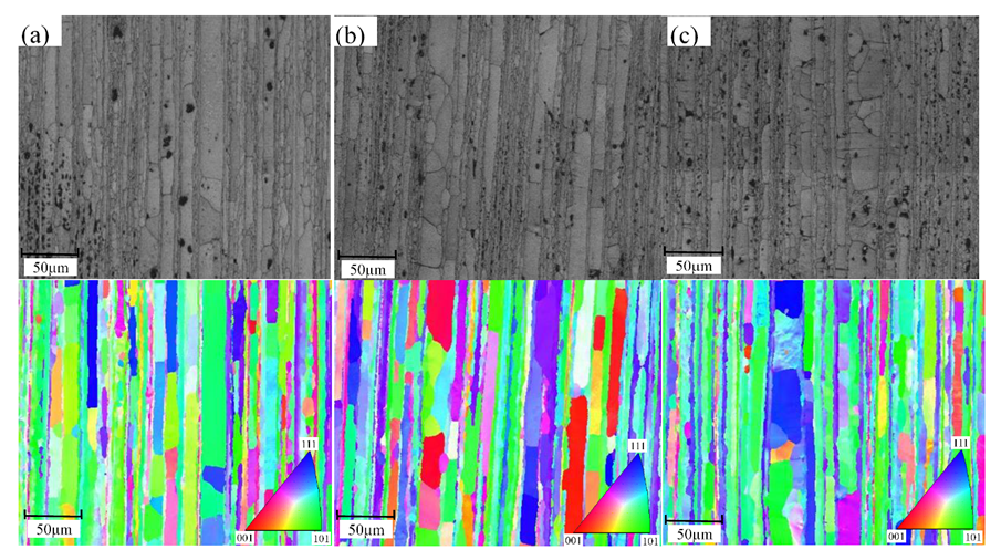
2.1. Experimental Material Preparation and Testing

Due to its excellent properties, 7050 aluminum alloy is widely used in various fields, especially in critical structural components in the aerospace field. The original material used for the experiments was 7050 aluminum alloy with a chemical composition of ≤0.04% of Cr, 1.9–2.6% of Cu, ≤0.15% of Fe, 1.9–2.6% of Mg, ≤0.10% of Mn, ≤0.12% of Si, ≤0.06% of Ti, 5.7–6.7% of Zn, 0.08–0.15% of Zr (all in wt.%), and the remaining composition was Al. A WDW-100 microcomputer-controlled electronic universal testing machine was used to obtain three groups of workpiece materials (with 10, 15, and 20% compression pre-deformation) with different crystal orientations. The crystal orientation information of three specimens was obtained using the electronic backscatter diffraction technique. The metallograph and crystal orientation diagram [23] and pole figure of the 7050 aluminum alloy with a different pre-deformation are shown in Figure 2 and Figure 3, respectively. The adjacent areas of the 7050 aluminum alloy surface show a typical rolled organization characterized by lamellar grains with a large boundary spacing range and different crystal orientations for the three 7050 aluminum alloy specimens in the figure. The highest density strength of 10% pre-deformed 7050 aluminum alloy was 9.83, and its texture was mainly {112} <111> copper texture and {110} <100> Goss texture. The highest density strength of the 15% pre-deformed 7050 aluminum alloy was 11.34, and its texture was mainly {112} <111> copper texture, {110} <100> Goss texture, and {001} <100> cube texture. Compared with the 10% pre-deformed 7050 aluminum alloy, the {110} <100> Goss texture and strength of 15% pre-deformed 7050 aluminum alloy decreased, its {112} <111> copper texture was enhanced, and a {001} <100> cube texture was observed. The highest density strength of 20% pre-deformed 7050 aluminum alloy was 10.00, and its texture was mainly {112} <111> copper and {110} <100> Goss. Compared with 15% pre-deformed 7050 aluminum alloy, the {110} <100> Goss texture strength and {112} <111> copper texture strength of 20% pre-deformed 7050 aluminum alloy increased and decreased, respectively. The different compressive pre-deformation amount makes the crystal orientation and texture of 7050 aluminum alloy different, which affects material properties and high-speed machinability.

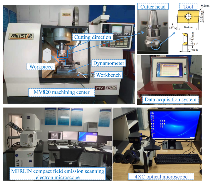
2.2. Experimental Equipment and Methods

A single-factor dry-cutting experimental scheme was set up with the following experimental variables: cutting speed, cutting depth, and feed rate. According to the actual production needs and cutting volume manual, the cutting parameters were set as follows: cutting speed (600, 900, 1200, 1500, and 1800 m/min), cutting depth (1.5 mm), and feed rate (0.1 mm/z); cutting depth (0.5, 1, 1.5, 2, and 2.5 mm), cutting speed (1500 m/min), and feed rate (0.1 mm/z); feed rate (0.025, 0.05, 0.075, 0.1, and 0.125 mm/z), cutting speed (1500 m/min), and cutting depth (1.5 mm). The high-speed cutting test was conducted on an MV820 CNC machining center, with a maximum spindle speed of 8000 r/min, a cutter head diameter of 80 mm, and a blade installed on the cutter head. An APKT1604PDER-MA H01 carbide tool with a tool fillet radius of 0.2 mm was selected. The machining method of up milling was adopted, and the machining direction was perpendicular to the direction of compression deformation. The three-dimensional cutting force during high-speed cutting was tested using a YD15-111 three-dimensional force measuring instrument. The cutting force took the maximum value of the spectrum of the force course, and three experiments were carried out to ensure the accuracy of the data. After the specimen was machined, a 4XC optical microscope was used to examine the two-dimensional and three-dimensional morphology of the machined surface. The tool topography was examined using a MERLIN compact field emission scanning electron microscope, and energy dispersive spectroscopy (EDS) was used to examine the elemental composition of the tool surface. Figure 4 shows the experimental and testing equipment.

3. Results and Discussion

3.1. The Analysis of Cutting Forces

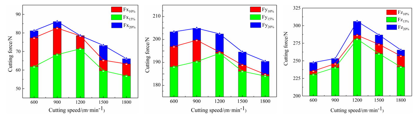
3.1.1. The Effect of Cutting Speed on the Three−Dimensional Cutting Force

Figure 5 depicts the effect of cutting speed on the three-dimensional cutting force of 7050 aluminum alloy with different crystal orientations. The three−dimensional cutting force initially increased and then decreased with the increase in cutting speed. The Z−direction cutting force (main cutting force) of 10% pre-deformed aluminum alloy decreased after reaching the maximum value at 1200 m/min, while the three−dimensional cutting force of 15% pre-deformed aluminum alloy increased to the maximum value at 1200 m/min. By comparing the three crystal orientations of 7050 aluminum alloys under the same cutting parameters, the overall three−dimensional cutting forces of 15% pre-deformed and 20% pre-deformed aluminum alloys were smaller and larger, respectively. This phenomenon could be attributed to the increase in cutting speed, which enhanced the tool cutting workpiece friction, tensile, and extrusion [4]. At the same time, the strain and strain rate increased, thus improving the strength of the material [2] and also increasing the cutting force, increasing the cutting speed, cutting the heat generated by too much to be taken away by the chip—so that as the temperature of the cutting area increased, the material exhibited a certain thermal softening [20]—and reducing the cutting force. Further analysis showed that the three-dimensional cutting forces of the three 7050 aluminum alloys were different. The differences in the cutting forces could be attributed to the different microscopic grain distributions and crystal orientation of the materials, which led to differences in dislocation and slip motion, the interaction of grains with different orientations, and changes in grain boundary characteristics when plastic deformation occurred in the material during cutting [11,24]. Given these factors, the material resisted deformation differently, corresponding to the differences in the three-dimensional cutting forces of the material under the same cutting parameters.

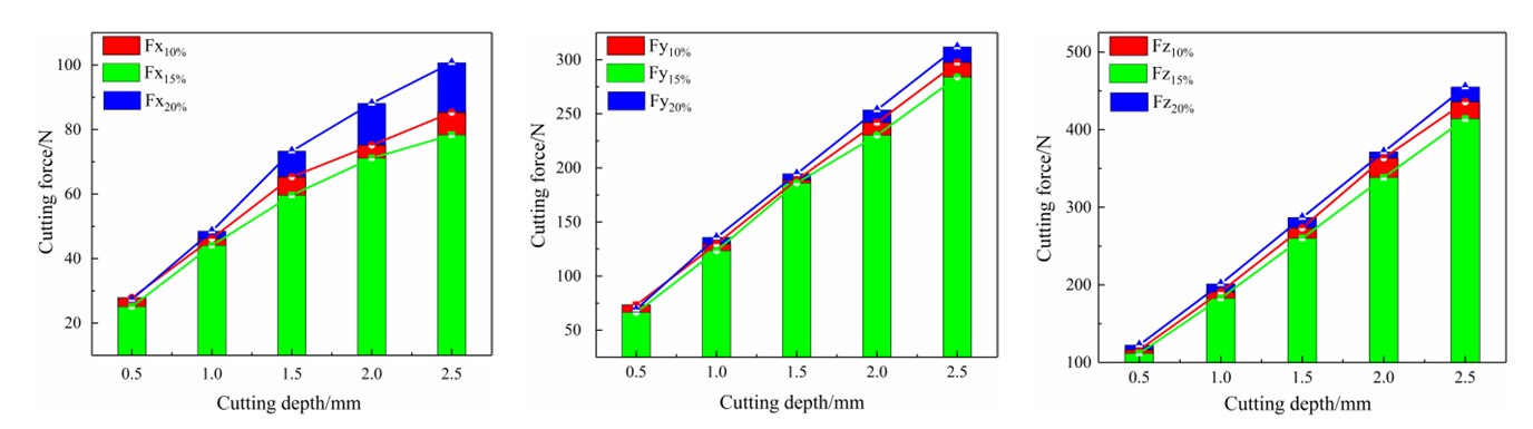
3.1.2. The Effect of Cutting Depth on Three−Dimensional Cutting Forces

Figure 6 depicts the effect of cutting depth on the three−dimensional cutting force of 7050 aluminum alloy with different crystal orientations. The three−dimensional cutting force was positively correlated with the cutting depth to a certain extent, and the increasing trend of cutting force in the X−direction was less than that in Y−direction and Z−direction. By comparing the three crystal orientations of 7050 aluminum alloys, the overall three−dimensional cutting forces of 15% pre-deformed and 20% pre-deformed 7050 aluminum alloys were smaller and larger, respectively. The cutting forces of 7050 aluminum alloys at different crystal orientations were different under the influence of cutting depth. The differences in cutting forces could be attributed to increased cutting depth, enhanced tool−chip and tool−workpiece between friction and extrusion, and increased workpiece material deformation resistance. Furthermore, when the cutting depth increased, the thickness of the cutting layer and the heat dissipation area increased, ultimately increasing the three−dimensional cutting force.

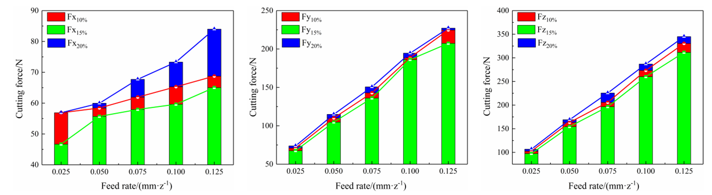
3.1.3. The Effect of Feed Rate on Three−Dimensional Cutting Forces

Figure 7 depicts the effect of feed rate on the three−dimensional cutting force of 7050 aluminum alloy with different crystal orientations. The three−dimensional cutting force positively correlated with the feed rate, and a slight variation in cutting force in X−direction was observed compared with that in Y−direction and Z−direction. By comparing the three crystal orientations of 7050 aluminum alloys, the overall three−dimensional cutting forces of 15% pre-deformed were smaller. The analysis showed that the feed rate correlated with the cutting depth, and an increase in feed rate changed the volume of material removed per cut [21], resulting in a consequent change in the cutting force, and the effect of the feed rate on the cutting force was influenced by several factors, such as the coordination and constraining effects between grains of different orientations, the interaction between dislocations and grain boundaries, and the deformation of grain boundaries [24,25].

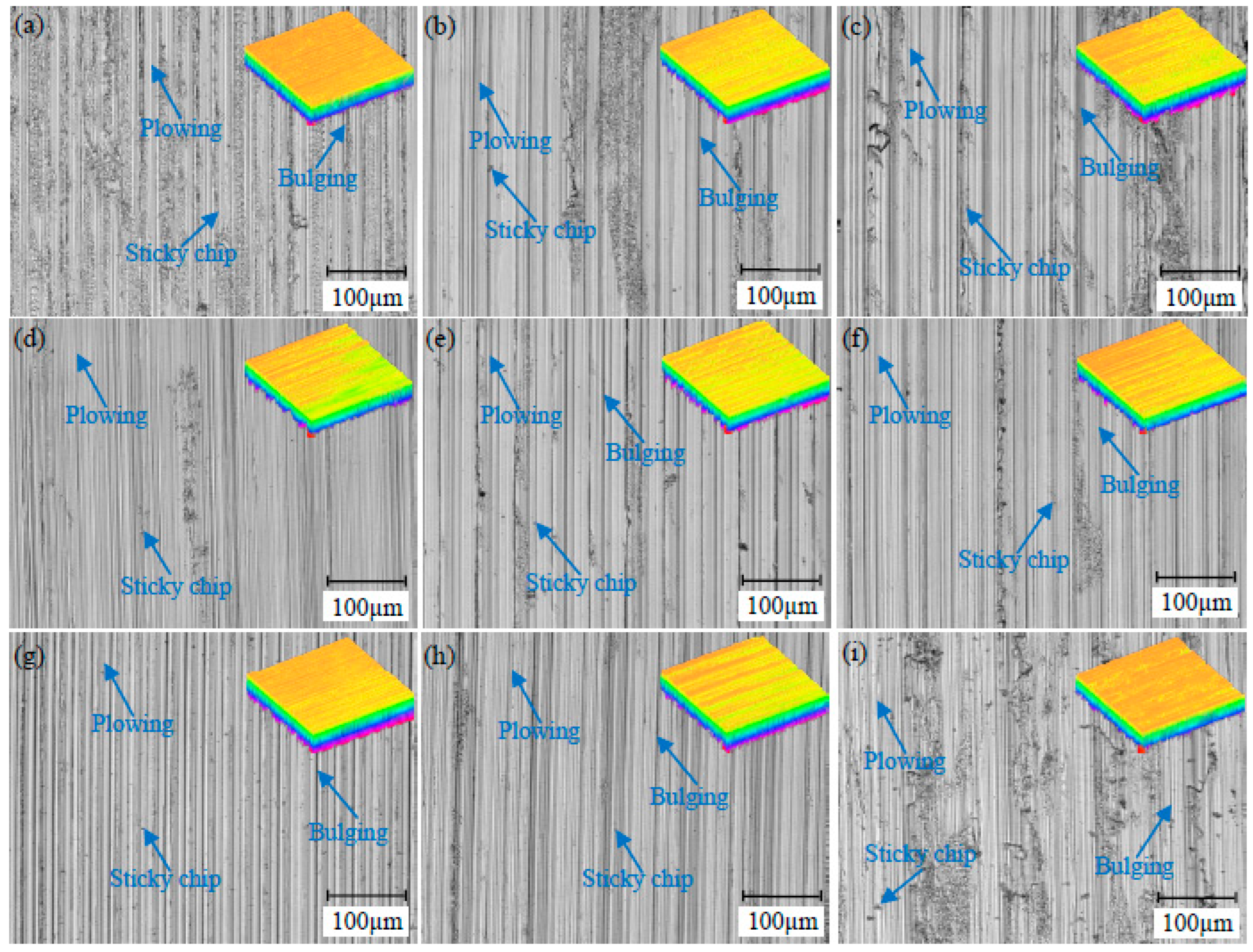
3.2. Analysis of Surface Topography in High-Speed Machining

3.2.1. Surface Morphology at Different Cutting Speeds

Figure 8 shows the surface morphology of 7050 aluminum alloys with different crystal orientations at different cutting speeds. At the cutting speed of 600 m/min, plowing, bulging, and a few sticky chips were observed on the machined surface (Figure 8a). At 1200 m/min, the plowing, burr, and sticky chip on the machining surface became more visible, wave valleys and peaks were observed, and the surface flatness and quality were poor (Figure 8b). At 1800 m/min, the plowing and bulging on the machining surface became shallower and lower (Figure 8c), and the phenomenon of chip sticking was observed. At 600 m/min, plowing and bulging were observed on the machined surface (Figure 8d), and at 1200 m/min, the machined surface plowing and bulging became more visible, and the surface quality was low (Figure 8e). At 1800 m/min, the machined surface plowing and bulging became smaller and shallower (Figure 8f), and the wave valley and peak changes were small, with improved surface quality. The machined surface in Figure 8g had more obvious plowing, bulging, and sticky chip, which adversely affected the quality of the machined surface. The sticky chips on the machined surface in Figure 8h appeared in a larger area due to the increased friction, extrusion between tool-chip and tool-workpiece, and increased heat generated by cutting [14], which intensified chip adhesion. The sticky chip on the machined surface reduced at 1800 mm/min (Figure 8i). By comparing the surface morphologies of the three crystal-oriented aluminum alloys, the surface morphology of 15% pre-deformed and 20% pre-deformed 7050 aluminum alloys was better and poor, respectively. Because 7050 aluminum alloy is a polycrystalline material, different compression pre-deformations produced different crystal orientations, which makes the microstructure deformation of the machined surface significantly different, thus affecting its elastic-plastic recovery [9,10], and making the surface morphology significantly different.

3.2.2. Surface Topography at Different Cutting Depths

Figure 9 shows the surface morphology of 7050 aluminum alloy with different crystal orientations at different cutting depths. At a smaller cutting depth of 0.5 mm, shallow plowing and bulging, less built-up edge, and sticky chips were observed on the machined surface (Figure 9a). As the cutting depth gradually increased, the amount of material removed per cut increased, the cutting force and cutting heat generated increased, the machined surfaces became uneven, and the surface quality deteriorated (Figure 9b,c). At a low cutting depth, sticky chips were observed on the machined surface (Figure 9d), and the whole surface was smooth. The cutting depth gradually increased to 1.5 mm. As shown in Figure 9e, the phenomenon of plowing, bulging, and sticky chips on the machining surface became serious, and the surface morphology worsened. When the cutting depth increased to 2.5 mm, the phenomenon of sticky chips on the machining surface reduced. At a high cutting speed and large cutting depth, the friction and extrusion of the flank would deteriorate the quality of the machined surface, the depth of cut would further increase, and the built-up edge would not be easily generated [26], thus reducing the phenomenon of chip sticking. With the increasing cutting depths, the surface finish became worse, and at large cutting depths, the sticky chips and surface residues increased, resulting in poor surface topography and poor surface quality (Figure 9g–i). In addition, the surface morphology of the 20% pre-deformed 7050 aluminum alloy was worse than that of the other two crystal orientation 7050 aluminum alloys. Due to the difference of crystal orientations, the generation and movement of dislocations and the limitation of grain boundaries during the cutting process were different [9,13], which leads to a change in elastic-plastic deformation properties and differences in surface morphology.

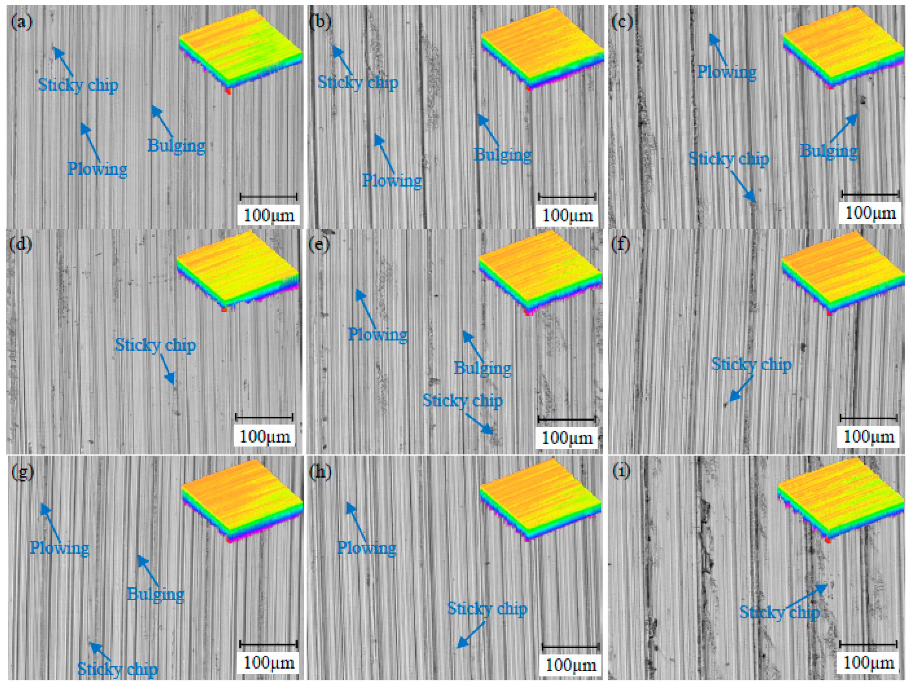
3.2.3. Surface Topography at Different Feed Rates

Figure 10 shows the surface morphology of 7050 aluminum alloys with different crystal orientations at different feed rates. At a feed rate of 0.025 mm/z, the sticky chips, plowing, and bulging on the machined surface were more visible (Figure 10a). As the feed rate gradually increased, the plastic deformation of the material during the cutting process and the heat generated by cutting increased [27]. As shown in Figure 10b,c, the surface quality of the machined surfaces was affected by the cutting heat and tool extrusion. As the sticky chips increased, the plowing and bulging became more pronounced, thus affecting the surface quality. At lower feed rates, the frequent extrusion of the machined surface by the tool would generate additional plastic deformation [28], resulting in poor surface quality. As the feed gradually increased, the machined surface residue increased, the sticky chips became pronounced, the machined surface became rough, and the surface quality gradually deteriorated (Figure 10d–f). At feed rates of 0.025 and 0.075 mm/z, plowing, bulging, and sticky chips were observed on the machined surfaces (Figure 10g,h). When the feed rate was increased to 0.125 mm/z, the surface residue on the machined surface increased and a large area of sticky chips occurred, resulting in poor surface morphology and poor surface quality. In addition, the surface morphology of 20% pre-deformed 7050 aluminum alloy was worse than that of 10% pre-deformed and 15% pre-deformed 7050 aluminum alloy.

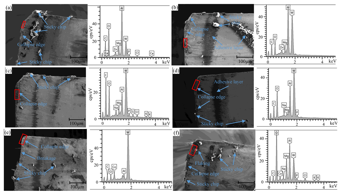
3.3. Analysis of Tool Wear in High-Speed Cutting

3.3.1. Tool Wear at Different Cutting Speeds

Figure 11 depicts the SEM and EDS images of the tool wear of 7050 aluminum alloy with different crystal orientations at different cutting speeds. The red framed area in the figure shows the EDS analysis area. At the cutting speed of 1200 m/min, the tool tip position of the cutting tool was severely worn (Figure 11a), the tool had a micro-collapse edge and flaking phenomenon, the built-up-edge formation occurred on the front tool surface, and the sticky chip existed on the rear tool surface. The chips were easily bonded to the tool surface, which produced adhesive wear. At the cutting speed of 1800 m/min, the tool surface showed a collapse edge, sticky chips, and adhesive layer (Figure 11b), which was attributed to the increase in cutting heat generated by high-speed cutting. As a result, the chips became molten and bonded on the tool surface and continuously extruded and accumulated under the action of cutting force to form an adhesive layer [19,29]. The elements at the wear site were Al, Mg, Zn, C, W, and O, and the wear mechanisms were mainly adhesive and oxidation wears. Collapse edge and sticky chips were observed on the tool surface (Figure 11c). However, EDS detected Al and Mg without Co. The Co element in the tool matrix that played a bonding role diffused, and the elements on the tool surface were oxidized at high temperatures. Thus, the wear mechanism was mainly adhesive, diffusion, and oxidation wears. Collapse edges, sticky chips, and adhesive layers were observed on the tool surface (Figure 11d), and the wear was weakened compared with that of the tool shown in Figure 11c. The content of O and Al was high among the elements, indicating that in the process of high-temperature cutting, the element O in the air reacted with the elements in the tool. Thus, the main wear mechanisms were adhesive, diffusion and oxidation wears. As shown in Figure 11e, the tool had a collapse edge, sticky chips, and severe breakage. Compared with Figure 11a,c, the wear was more serious. The content of O and Al elements at the wear position of the tool tip was low; the wear mechanism was mainly adhesive wear. As shown in Figure 11f, collapse edges, large flaking, and sticky chips were observed on the tool surface. The contents of Al, Mg, and O were high; thus, the wear mechanisms were mainly diffusion and oxidation wear. By comparing the tool wear of three 7050 aluminum alloys at different cutting speeds, the tool wear of the crystal orientation (15% pre-deformed aluminum alloy) was lighter. Because the different crystal orientations of aluminum alloy affected the slip, a deformation of the surface grains and the slip friction state between the tool and chip occurred [9,10]. Differences in the interaction between the grains and grain boundaries of different orientations were observed, and the combined effect of all factors led to a difference in tool wear.

3.3.2. Tool Wear at Different Cutting Depths

Figure 12 depicts the SEM and EDS images of the tool wear of 7050 aluminum alloy with different crystal orientations at different cutting depths. The red framed area in the figure shows the EDS analysis area. At the cutting depth of 1 mm, the surface of the tool had a collapse edge and more sticky chips (Figure 12a), and the contents of O and Al elements were high; thus, the tool wear mechanisms were adhesive and oxidation wears. At the cutting depth of 2 mm, the surface of the tool showed collapse edge, flaking, and large adhesion at the surface of tool (Figure 12b), and the wear mechanisms were diffusion and oxidation wear. Collapse edge and sticky chips were observed on the surface of the tool (Figure 12c). The content of W was the highest, and the tool wear mechanisms were mainly adhesive and oxidation wears. Collapse edge, sticky chips, and adhesive layers appeared on the tool surface (Figure 12d), which were more severely worn and damaged than those on the tool surface shown in Figure 12c. The contents of W and Co elements were low. Thus, the wear mechanisms were adhesive and diffusion wears. Collapse edge, grooves, and sticky chips appeared on the surface of the tool (Figure 12e), because the “high temperature” sticky chip continuously scraped the “cold” cutting edge [30], thus forming the groove, and the tool wear mechanism was mainly adhesive wear. The surface of the tool showed more severe breakage and sticky chips (Figure 11f). The content of O and Al elements were relatively higher. Thus, the wear mechanisms were mainly adhesive, diffusion, and oxidation wears. By comparing the tool wear of three different crystal orientations of 7050 aluminum alloys at different cutting depths, the tool wear of 15% pre-deformed 7050 aluminum alloy was lighter.

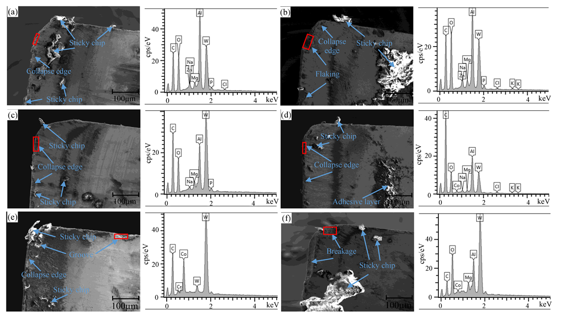
3.3.3. Tool Wear at Different Feed Rates

Figure 13 depicts the SEM and EDS images of the tool wear of 7050 aluminum alloy with different crystal orientations at different feed rates. The red framed area in the figure shows the EDS analysis area. At the feed rate of 0.05 mm/z, collapse edge, and numerous sticky chips appeared on the front and rear surfaces (Figure 13a). The EDS analysis result showed that the contents of O and Al elements were higher, indicating that the tool wear mechanisms were adhesive wear and oxidation wear. At the feed rate of 0.1 mm/z, a collapse edge, sticky chips, and an adhesive layer were observed on the surface of the tool (Figure 13b), which were more severe than those on the surface shown in Figure 13a. The friction and extrusion between the tool and the workpiece generated cutting heat, which reduced the fatigue strength of the tool and led to a collapse edge, and the wear mechanisms were adhesive and oxidation wears. The tool shown in Figure 13c shows a collapse edge and sticky chips. According to EDS analysis, the main elements at the wear site were W, C, Al, Mg, and O, and no Co element was detected, indicating that the wear mechanisms were adhesive, diffusion, and oxidation wears. The tool in Figure 13d shows a micro-collapse edge, sticky chips, and a larger adhesive layer on the tool surface. The EDS analysis showed that the content of O elements was higher, and oxidation was severe. Thus, the tool wear mechanisms were adhesive and oxidation wears. The crater wear on the rake face and sticky chips on both the front and rear rake faces are in Figure 13e. The workpiece and tool materials were cold-welded, and the relative movement caused the surface material of the rake surface to tear, forming crescent wear. The elements contents of O and Al in the crater wear were relatively higher; thus, the wear mechanisms of the tool were adhesive, diffusion, and oxidation wears. The tool in Figure 13f showed crater wear and collapse edge, and sticky chips appear on the front and rear tool surfaces. After the tool was in contact with the chip during high-speed cutting, thermal softening occurred in the contact area under high temperature and high pressure. The tool material was bonded to the chip and flowed out with the chip, resulting in crater wear [29]. The main elements of crater wear were W, C, Al, Mg, and O, among which the contents of O and Al were higher, and the wear mechanisms were adhesive, oxidation, and diffusion wears. By comparing the tool wear of three 7050 aluminum alloys at different feed rates, the tool wear of 15% pre-deformed 7050 aluminum alloy was lighter.

4. Conclusions

The three−dimensional cutting force of 7050 aluminum alloy with prefabricated crystal orientation initially increased and then decreased with the increase in cutting speed. At a cutting speed of 1800 m/min, the three−dimensional cutting force of 15% pre-deformed aluminum alloy was 90.8%, 96.5%, and 85.6% of a 20% pre-deformed aluminum alloy.
Under different cutting parameters, different crystal orientations of 7050 aluminum alloy machining surfaces showed different degrees of plowing, bulging, built-up edge adhesion, sticky chips, and other phenomena. By comparing the surface topography of the three aluminum alloys, the surface topography of a 15% pre-deformed aluminum alloy was better than that of 10 and 20% pre-deformed aluminum alloys.
During the high-speed cutting process of the 7050 aluminum alloy, the wear mechanisms were adhesive, diffusion, and oxidation wears; meanwhile, tool wear was improved with increasing cutting speed. Under the same cutting parameters, 15% pre-deformed aluminum alloy tool wear was lighter.
Future research should consider the effects of tool parameters and the cutting environment, as well as establish finite element models to deeply analyze the machinability of aluminum alloys with a prefabricated crystal orientation from a microscopic perspective.

Author Contributions

Conceptualization, C.N., W.L. and Y.W.; methodology, C.N., W.L. and C.Z.; validation, C.N., W.L. and C.Z.; formal analysis, C.N. and W.L.; investigation, C.N., D.L. and G.L.; data curation, C.N., W.L. and D.L.; writing—original draft preparation, C.N.; writing—review and editing, W.L., Y.W. and C.Z.; supervision, W.L., Y.W. and C.Z.; project administration, C.N., C.Z. and G.L.; funding acquisition, C.N., C.Z. and G.L. All authors have read and agreed to the published version of the manuscript.

Funding

This research was funded by Shandong Provincial Natural Science Foundation, China (Grant No. ZR2023QE041, Grant No. ZR2020QE181), and China Postdoctoral Science Foundation (Grant No. 2023M731862).

Data Availability Statement

Data sharing not applicable.

Conflicts of Interest

The authors declare no conflict of interest.

References

  1. Manjunath, G.A.; Shivakumar, S.; Avadhani, S.P.; Sharath, P. Investigation of mechanical properties and microstructural behavior of 7050 aluminium alloy by multi directional forging technique. Mater. Today Proc. 2020, 27, 1147–1151. [Google Scholar] [CrossRef]
  2. Yu, X.; Wang, Y.; Lv, D. A novel chip breaker structure of PCD tool for the reaming of 7050 aluminum alloy. Int. J. Adv. Manuf. Technol. 2020, 109, 659–672. [Google Scholar] [CrossRef]
  3. Yu, X.W.; Chen, J.H.; Li, J.Y.; Wu, C.L. Effect of pre-deformation on quench-induced inhomogeneity of microstructure and hardness in 7050 aluminum alloy. Mater. Charact. 2019, 158, 110005. [Google Scholar] [CrossRef]
  4. Soren, T.R.; Kumar, R.; Panigrahi, I.; Sahoo, A.K.; Panda, A.; Das, R.K. Machinability behavior of Aluminium Alloys: A Brief Study. Mater. Today Proc. 2019, 18, 5069–5075. [Google Scholar] [CrossRef]
  5. Demir, H.; Gündüz, S. The effects of aging on machinability of 6061 aluminium alloy. Mater. Des. 2008, 30, 1480–1483. [Google Scholar] [CrossRef]
  6. Barnwal, V.K.; Raghavan, R.; Tewari, A.; Narasimhan, K.; Mishra, S.K. Effect of microstructure and texture on forming behaviour of AA-6061 aluminium alloy sheet. Mater. Sci. Eng. A 2017, 679, 56–65. [Google Scholar] [CrossRef]
  7. Wu, X.; Li, L.; He, N.; Zhao, M.; Zhan, Z. Investigation on the influence of material microstructure on cutting force and bur formation in the micro cutting of copper. Int. J. Adv. Manuf. Technol. 2015, 79, 321–327. [Google Scholar] [CrossRef]
  8. Lawson, B.L.; Kota, N.; Ozdoganlar, O.B. Effects of Crystallographic Anistropy on Orthogonal Micromachining of Single-Crystal Aluminum. J. Manuf. Sci. Eng. 2008, 130, 031116. [Google Scholar] [CrossRef]
  9. Komanduri, R.; Chandrasekaran, N.; Raff, L.M.D. Simulation of nanometric cutting of single crystal aluminum–effect of crystal orientation and direction of cutting. Wear 2000, 242, 60–88. [Google Scholar] [CrossRef]
  10. Wang, Z.; Zhang, J.; Li, G.; Xu, Z.; Zhang, H.; Zhang, J.; Hartmaier, A.; Fang, F.; Yan, Y.; Sun, T. Anisotropy-Related Machining Characteristics in Ultra-Precision Diamond Cutting of Crystalline Copper. Nanomanufacturing Metrol. 2020, 3, 123–132. [Google Scholar] [CrossRef]
  11. Guo, X.; Gou, Y.; Dong, Z.; Yuan, S.; Li, M.; Du, W.; Kang, R. Study on subsurface layer of nano-cutting single crystal tungsten in different crystal orientations. Appl. Surf. Sci. 2020, 526, 146608. [Google Scholar] [CrossRef]
  12. Ding, X.; Rahman, M. A study of the performance of cutting polycrystalline Al 6061 T6 with single crystalline diamond mi-cro-tools. Precis. Eng. 2012, 36, 593–603. [Google Scholar] [CrossRef]
  13. Zhao, M.; Ji, X.; Liang, S.Y. Influence of AA7075 crystallographic orientation on micro-grinding force. Proc. Inst. Mech. Eng. Part B J. Eng. Manuf. 2018, 233, 1831–1843. [Google Scholar] [CrossRef]
  14. Ayed, Y.; Robert, C.; Germain, G.; Ammar, A. Orthogonal micro-cutting modeling of the Ti17 titanium alloy using the crystal plasticity theory. Finite Elements Anal. Des. 2017, 137, 43–55. [Google Scholar] [CrossRef]
  15. Goel, S.; Luo, X.; Reuben, R.L.; Pen, H. Influence of temperature and crystal orientation on tool wear during single point diamond turning of silicon. Wear 2012, 284–285, 65–72. [Google Scholar] [CrossRef]
  16. Hao, Z.; Gao, D.; Fan, Y.; Han, R. New observations on tool wear mechanism in dry machining Inconel718. Int. J. Mach. Tools Manuf. 2011, 51, 973–979. [Google Scholar] [CrossRef]
  17. Liu, Z.; Yue, C.; Li, X.; Liu, X.; Liang, S.Y.; Wang, L. Research on Tool Wear Based on 3D FEM Simulation for Milling Process. J. Manuf. Mater. Process. 2020, 4, 121. [Google Scholar] [CrossRef]
  18. Sánchez, J.M.; Rubio, E.; Álvarez, M.; Sebastián, M.; Marcos, M. Microstructural characterisation of material adhered over cutting tool in the dry machining of aerospace aluminium alloys. J. Mater. Process. Technol. 2005, 164–165, 911–918. [Google Scholar] [CrossRef]
  19. Sharif, A. Study on burr formation, tool wear and surface quality in machining Al6063. J. Mater. Manuf. 2022, 1, 1–9. [Google Scholar] [CrossRef]
  20. Sharif, A.; Hussain, A.; Habib, N.; Alam, W.; Hanif, M.I.; Noon, A.A.; Khan, M.I. Experimental investigation of hole quality and chip analysis during the dry drilling process of Al6061-T6. J. Mater. Manuf. 2023, 2, 21–30. [Google Scholar]
  21. Dong, G.; Wang, X.; Gao, S. Molecular dynamics simulation and experiment research of cutting-tool wear mechanism for cutting aluminum alloy. Int. J. Adv. Manuf. Technol. 2018, 96, 1123–1137. [Google Scholar] [CrossRef]
  22. Zhang, P.; Zhang, X.; Cao, X.; Yu, X.; Wang, Y. Analysis on the tool wear behavior of 7050-T7451 aluminum alloy under ultrasonic elliptical vibration cutting. Wear 2021, 466, 203538. [Google Scholar] [CrossRef]
  23. Lu, W.; Zong, C.; Ni, C.; Yu, X.; Liu, D. Study on the surface integrity of 7050 aluminum alloy with different crystal orientations during high-speed machining. Int. J. Adv. Manuf. Technol. 2022, 125, 661–678. [Google Scholar] [CrossRef]
  24. Wang, Z.F.; Zhang, J.; Zhang, J.; Li, G.; Zhang, H.; Hassan, H.U.; Hartmaier, A.; Yan, Y.; Sun, T. Towards an understanding of grain boundary step in diamond cutting of polycrystalline copper. J. Mater. Process. Technol. 2020, 276, 116400. [Google Scholar] [CrossRef]
  25. Zhang, P.; Wang, Y. The Influence of Heat Treatment on Nanoscale Microstructure and Crystal Orientation of 7055 Aluminum Alloy Before and After High-Speed Milling. Trans. Indian Inst. Met. 2018, 71, 1379–1387. [Google Scholar] [CrossRef]
  26. Liu, W.H.; Yang, X.L.; Zhang, P.; Chen, Y.; Tang, S. Effect of T6 and T6I4 aging treatment on machinability of 7055 aluminum alloy. Trans. Mater. Heat Treat. 2016, 37, 30–35. [Google Scholar] [CrossRef]
  27. Ping, Z.; Xiujie, Y.; Penghao, W.; Xiao, Y. Surface integrity and tool wear mechanism of 7050-T7451 aluminum alloy under dry cutting. Vacuum 2020, 184, 109886. [Google Scholar] [CrossRef]
  28. Luo, H.; Wang, Y.; Zhang, P. Study on Surface Quality of 7A09 aluminum alloy milling based on single factor method. Surf. Technol. 2020, 49, 327–333. [Google Scholar] [CrossRef]
  29. Wu, Z.Y.; Zheng, G.M.; Jiang, X.L.; Yang, X.H.; Li, X.W.; Liu, H.B. Wear mechanism of TIAISIN coating in high speed dry turning of titanium alloy. Modul. Mach. Tool Autom. Manuf. Technol. 2022, 6, 172–179. [Google Scholar] [CrossRef]
  30. Li, X.; Zhou, Y.; Liu, J.; Gao, J. Research on wear mechanism of carbide tool for high-speed cutting aluminum alloy. Powder Met-Allurgy Technol. 2018, 36, 256–260. [Google Scholar] [CrossRef]
Figure 1. A schematic research plan.
Lubricants 11 00413 g001
Figure 2. A metallograph and crystal orientation diagram of different pre-deformed 7050 aluminum alloy (a) 10% pre-deformation, (b) 15% pre-deformation, (c) 20% pre-deformation.
Lubricants 11 00413 g002
Figure 3. Pole figures of different pre-deformed 7050 aluminum alloy (a) 10% pre-deformation, (b) 15% pre-deformation, (c) 20% pre-deformation.
Lubricants 11 00413 g003
Figure 4. Experimental and testing equipment.
Lubricants 11 00413 g004
Figure 5. The effect of cutting speed on three−dimensional cutting forces.
Lubricants 11 00413 g005
Figure 6. The effect of cutting depth on three−dimensional cutting forces.
Lubricants 11 00413 g006
Figure 7. The effect of feed rate on three−dimensional cutting forces.
Lubricants 11 00413 g007
Figure 8. The surface morphology of 7050 aluminum alloy with different crystal orientations at different cutting speeds (a) 600 m/min (10% pre-deformed), (b) 1200 m/min (10% pre-deformed), (c) 1800 m/min (10% pre-deformed), (d) 600 m/min (15% pre-deformed), (e) 1200 m/min (15% pre-deformed), (f) 1800 m/min (15% pre-deformed), (g) 600 m/min (20% pre-deformed), (h) 1200 m/min (20% pre-deformed), (i) 1800 m/min (20% pre-deformed).
Lubricants 11 00413 g008
Figure 9. The surface morphology of 7050 aluminum alloy with different crystal orientations at different cutting depths (a) 0.5 mm (10% pre-deformed), (b) 1.5 mm (10% pre-deformed), (c) 2.5 mm (10% pre-deformed), (d) 0.5 mm (15% pre-deformed), (e) 1.5 mm (15% pre-deformed), (f) 2.5 mm (15% pre-deformed), (g) 0.5 mm (20% pre-deformed), (h) 1.5 mm (20% pre-deformed), (i) 2.5 mm (20% pre-deformed).
Lubricants 11 00413 g009
Figure 10. The surface morphology of 7050 aluminum alloy with different crystal orientations at different feed rates (a) 0.025 mm (10% pre-deformed), (b) 0.075 mm/z(10% pre-deformed), (c) 0.125 mm/z (10% pre-deformed), (d) 0.025 mm (15% pre-deformed), (e) 0.075 mm/z (15% pre-deformed), (f) 0.125 mm/z (15% pre-deformed), (g) 0.025 mm (20% pre-deformed), (h) 0.075 mm/z (20% pre-deformed), (i) 0.125 mm/z (20% pre-deformed).
Lubricants 11 00413 g010
Figure 11. The SEM and EDS images of tool wear of 7050 aluminum alloy with different crystal orientations at different cutting speeds (a) 1200 m/min (10% pre-deformed), (b) 1800 m/min (10% pre-deformed), (c) 1200 m/min (15% pre-deformed), (d) 1800 m/min (15% pre-deformed), (e) 1200 m/min (20% pre-deformed), (f) 1800 m/min (20% pre-deformed).
Lubricants 11 00413 g011
Figure 12. The SEM and EDS images of the tool wear of 7050 aluminum alloy with different crystal orientations at different cutting depths (a) 1 mm (10% pre-deformed), (b) 2 mm (10% pre-deformed), (c) 1 mm (15% pre-deformed), (d) 2 mm (15% pre-deformed), (e) 1 mm (20% pre-deformed), (f) 2 mm (20% pre-deformed).
Lubricants 11 00413 g012
Figure 13. The SEM and EDS images of the tool wear of 7050 aluminum alloy with different crystal orientations at different feed rates (a) 0.05 mm/z (10% pre-deformed), (b) 0.1 mm/z (10% pre-deformed), (c) 0.05 mm/z (15% pre-deformed), (d) 0.1 mm/z (15% pre-deformed), (e) 0.05 mm/z (20% pre-deformed), (f) 0.1 mm/z (20% pre-deformed).
Lubricants 11 00413 g013
Disclaimer/Publisher’s Note: The statements, opinions and data contained in all publications are solely those of the individual author(s) and contributor(s) and not of MDPI and/or the editor(s). MDPI and/or the editor(s) disclaim responsibility for any injury to people or property resulting from any ideas, methods, instructions or products referred to in the content.

