1. Introduction
The rapid growth of global industries has presented significant challenges such as the energy depletion crisis and environmental pollution [
1]. Among pressing concerns, the detrimental impact of greenhouse gas emissions on industrial development has become a critical issue [
2]. In response to industrial evolution witnessed since the twentieth century, there is an urgent need for a transition toward greenhouse gas reduction and the adoption of eco-friendly energy systems to sustain the continuous growth of national economies [
3].
Recognizing the potential of water and hydrogen as renewable and sustainable resources for eco-friendly energy conversion, hydrogen energy utilization has emerged as a viable alternative to address environmental pollution and energy scarcity [
4,
5]. Hydrogen, being a common element, constitutes over 70% of the universe’s mass and is a component of water, which accounts for approximately 70% of the Earth’s mass [
6]. In addition to its abundance, hydrogen boasts low harmful gas emissions and renewability, rendering it indispensable for the development of eco-friendly energy systems.
Hydrogen refueling stations, which form the core of hydrogen infrastructure, are responsible for supplying fuel to vehicles and storage bases [
7,
8]. Hydrogen gas is compressed at high pressure, reaching approximately 700 bar, and is stored in gas tanks at these refueling stations [
9]. Among the compression methods employed, diaphragm compressors have garnered attention for their ability to produce high-purity gas without leakage under high pressure, making them advantageous for hydrogen gas production compared to other compressor types [
10].
The diaphragm compressor comprises essential components, including a driving part for power generation and transmission, a head part responsible for gas compression, and a diaphragm plate that isolates the gas from the actuating oil and facilitates gas compression [
11]. The diaphragm plate is a critical element consisting of three layers: an oil diaphragm in contact with the actuating oil, a gas diaphragm in contact with the gas, and a middle diaphragm positioned between these two layers. This unique triple structure effectively isolates gas from the actuating oil, ensuring the production of high-purity gas, thereby making it the preferred method for high-pressure hydrogen gas compression. Despite its advantages, diaphragm compressors are subject to certain limitations, particularly with regard to flow capacity. To enhance gas production, it becomes necessary to expand the area, leading to stress caused by plate sagging when it contacts the cavity surface, ultimately causing fatigue failure.
In the field of diaphragm compressors for hydrogen gas production, several studies have explored stress and deformation in the cylinder head under high-temperature and high-pressure conditions, predicting the component’s lifespan based on thermal-structural combined analysis [
12]. Additionally, a work of research proposed a model to investigate the fatigue characteristics of diaphragm plates under various load conditions, aiming to verify their reliability [
13]. Another research work revealed the significance of actuating oil pressure and outlet hole diameters as factors affecting the fatigue life of the diaphragm [
14].
While previous studies have primarily focused on the radius stress and cavity shape, limited research has been dedicated to diaphragm plates, which play a pivotal role in the fatigue life of diaphragm compressors. During compressor operation, diaphragm plates experience elastic deformation within their limits. However, repeated deformation processes may lead to micro-slipping scratches between diaphragm plates and plastic deformation damage, potentially resulting in severe repercussions for gas production. External forces from the piston deform the diaphragm plate, causing bending and tensile stress. The type of stress experienced by the diaphragm plate determines the conversion of bending stress into radial tensile stress from the plate center, resulting in impacts and micro-friction between diaphragm plates. As such, the diaphragm plate emerges as the most critical factor influencing gas compressibility and the lifespan performance of diaphragm compressors. Therefore, it is imperative to investigate the characteristics of friction and wear to prevent damage caused by micro-impacts and friction on the diaphragm plate and to enhance its lifespan.
Improving the friction and wear characteristics of diaphragm plates necessitates accompanying surface treatments. Techniques such as coating and polishing enhance the wear resistance of materials by reducing their adhesive properties or improving their mechanical strength. Surface polishing can reduce unnecessary contact and friction during interactions by eliminating irregularities or protrusions on the material’s surface [
15]. Notably, a smooth surface has the advantage of dispersing wear and reducing concentrated stress, thereby mitigating temperature increases and wear due to friction. However, polishing demands precise and consistent performance, typically involving complex processes.
Among numerous coating materials, Teflon is well known for its non-stick properties and high-temperature resistance [
16,
17]. This suggests that when applied as a diaphragm surface coating, Teflon exhibits low-friction characteristics that could potentially enhance its lifespan. However, given that Teflon has lower strength compared to metal, it is essential to investigate its friction and wear characteristics during contact sliding processes with metal.
This study aims to assess the durability of diaphragm plates, focusing on the impact of surface treatment and material types. Specifically, we investigated the effects of surface polishing and coating on the mechanical properties, friction, and wear characteristics of diaphragm plates. Through a comprehensive evaluation, we analyzed the surface, mechanical, and tribological properties of the diaphragm plate, further utilizing finite element analysis simulation to examine stress distribution and deformation characteristics. By conducting a thorough investigation into diaphragm plate durability, this research seeks to enhance the performance and reliability of hydrogen diaphragm compressors. The outcomes hold the potential to drive advancements in hydrogen energy utilization, significantly contributing to the addressing of environmental challenges and promoting sustainable energy practices in industrial applications.
3. Results and Discussion
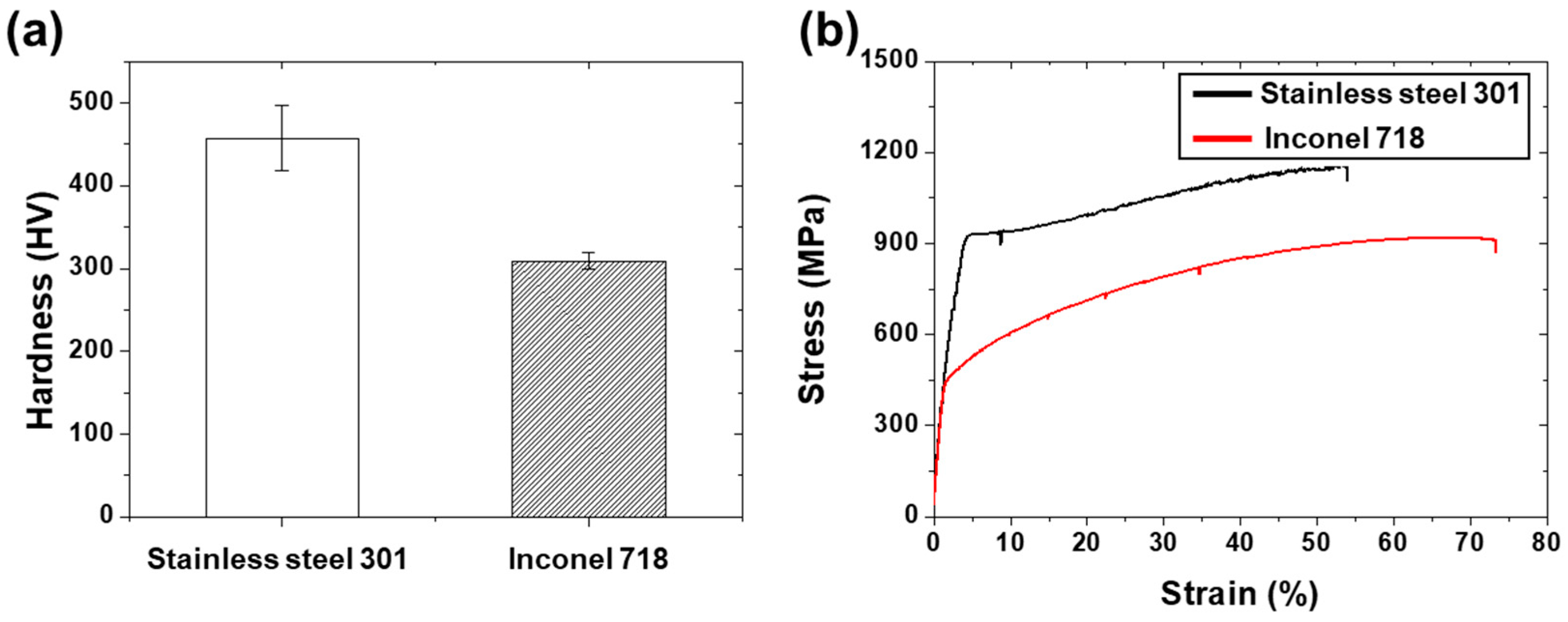
Figure 1a presents the Vickers hardness values of stainless steel 301 and Inconel 718, measuring 457 HV and 303 HV, respectively. Notably, stainless steel 301 exhibits a higher surface hardness value, approximately 50% greater than that of Inconel 718. Moving on to
Figure 1b, the stress–strain curve of Inconel 718 showcases a tensile strength of 916 MPa and a yield strength of 536 MPa. The Inconel 718 demonstrated a maximum displacement of 36.7 mm during the tensile test, with an elongation of 73.5% and an elastic modulus of 65 GPa. In contrast, stainless steel 301 exhibits higher tensile strength (1168 MPa) and yield strength (716 MPa) compared to Inconel 718, with a smaller maximum displacement of 27 mm. The deformation of the stainless steel 301 specimen resulted in an elongation of 54.1%, and its elastic modulus slightly surpassed that of Inconel 718, measuring 67 GPa. Upon analyzing the stress–strain curve, it becomes evident that stainless steel 301 possesses higher tensile and yield strength, indicating superior resistance to deformation under applied loads [
18]. However, Inconel 718 showcases remarkable ductility and plastic deformation properties, evident from its higher elongation and maximum displacement values [
19]. Moreover, the elastic modulus values indicate that the two materials have a similar degree of stiffness.
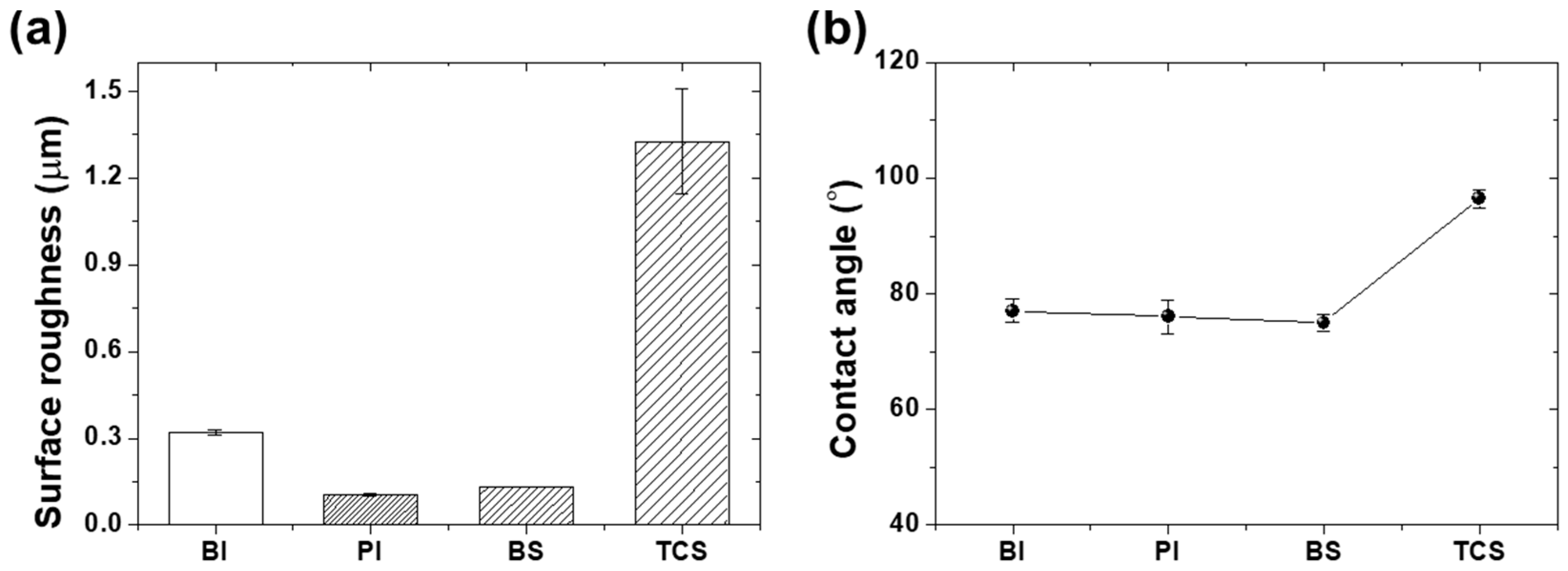
The surface characteristics of the diaphragm materials were analyzed based on their surface treatments using measurements of surface roughness and water droplet contact angles.
Figure 2a presents the surface roughness values of all specimens (BI, PI, BS, TCS), which are 0.32 μm, 0.1 μm, 0.13 μm, and 1.33 μm, respectively. The surface roughness of PI is the smallest due to the surface polishing process, whereas TCS exhibits the highest value owing to the presence of Teflon particles coated on its surface.
Figure 2b displays the water droplet contact angles of each specimen, with contact angles of 77°, 76°, 74°, and 96° for BI, PI, BS, and TCS, respectively. Inconel 718 and stainless steel 301 are considered hydrophilic materials, resulting in relatively small contact angles on the substrate surface due to their high affinity with water at the interface when in contact [
20,
21]. However, Teflon exhibits a higher contact angle compared to the other metal substrates due to its inherent hydrophobic nature [
22]. Although there is no significant difference in the water droplet contact angle between the two metals, the contact angle increased with the application of the Teflon coating.
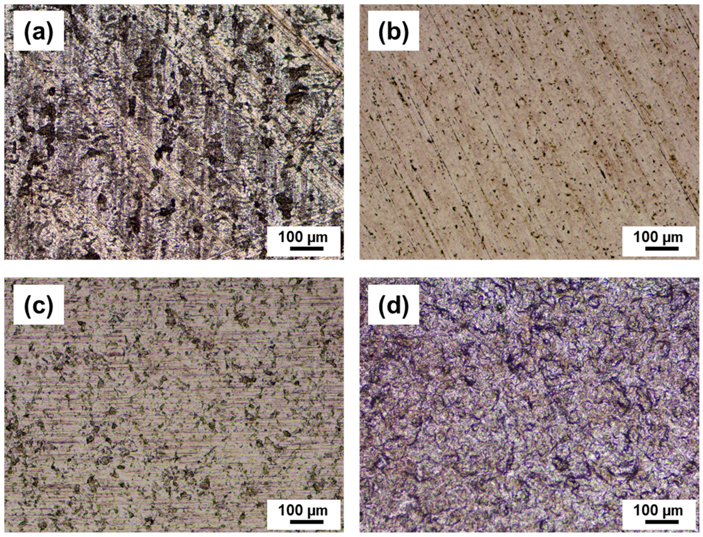
Figure 3 illustrates the surface morphologies of the specimens. BI exhibits a very rough surface morphology, while the surface of PI appears very smooth. On the other hand, the surface of TCS displays an uneven distribution of rough particles, and BS exhibits a surface morphology similar to that of PI.
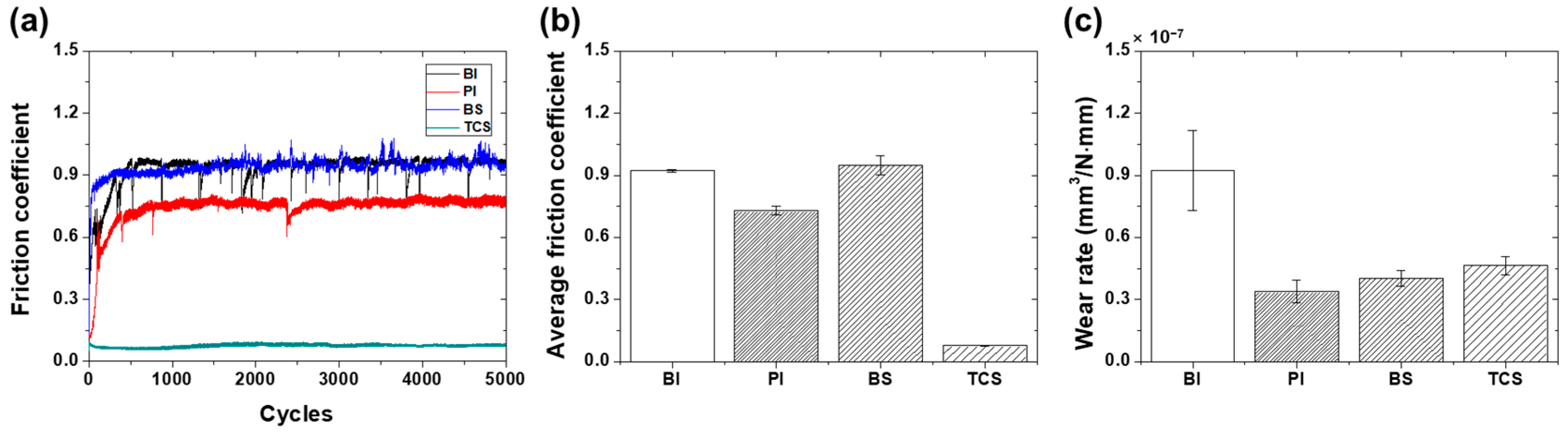
In this study, the friction and wear characteristics of the specimens were evaluated through tribotests conducted over 5000 cycles at a speed of 4 mm/s under a normal load of 100 mN. Based on Hertzian contact theory, the contact pressures for Inconel 718 and stainless steel 301 were calculated as 612 MPa and 613 MPa, respectively, while that of Teflon was 34 MPa [
23].
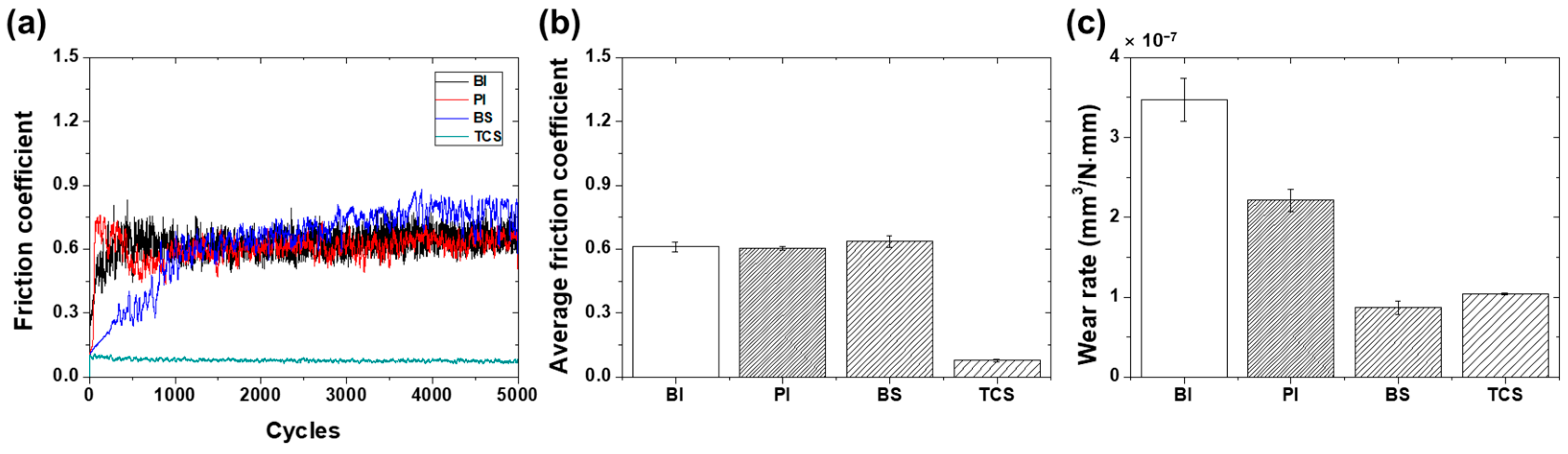
Figure 4a illustrates the friction coefficient history of each specimen during the sliding cycles. For bare Inconel (BI), the friction coefficient started below 0.5 initially, rapidly increased to over 0.9 within 500 cycles, and then remained relatively constant with slight fluctuations throughout the entire sliding cycle. Bare stainless steel (BS) began with a higher initial friction coefficient compared to BI, but after gradually increasing to approximately 0.9, the value was sustained with severe fluctuations. Polished Inconel (PI) began with a low friction coefficient of approximately 0.1, rapidly increased to 0.6 within the first 100 cycles, then decreased temporarily, followed by a gradual increase to 0.7 over hundreds of cycles. Subsequently, the friction coefficient remained constant, with a sudden decrease occurring around 2300 cycles, after which it returned to the original value and remained stable for the remainder of the test. Teflon-coated stainless steel (TCS) maintained a constant friction coefficient of 0.08 throughout the entire test duration.
Figure 4b depicts the average friction coefficient values of each specimen. The average friction coefficients for BI and BS, which are bare Inconel and stainless steel specimens without surface treatment, were as high as 0.92 and 0.95, respectively. In contrast, the average friction coefficient of polished Inconel (PI) decreased slightly to 0.73, while that of TCS coated with Teflon on stainless steel was 0.08, representing the lowest average friction coefficient with a 92% decrease compared to BS. Following the tribotests, the wear tracks formed on the specimen surfaces were analyzed through a 2D profiler, and the wear rate was calculated, as shown in
Figure 4c. The wear rate (mm
3/N·mm) was calculated by dividing the wear volume obtained from measuring the wear width and depth of the wear track by the normal load and total sliding distance [
24,
25]. The wear rates for BI, PI, BS, and TCS were 0.92 × 10
−7 mm
3/N·mm, 0.34 × 10
−7 mm
3/N·mm, 0.40 × 10
−7 mm
3/N·mm, and 0.46 × 10
−7 mm
3/N·mm, respectively. The wear rate of BI was the highest, while PI exhibited the smallest wear rate. The surface of BI, being bare Inconel without surface treatment, displayed numerous patterns and protrusions, such as processing traces, leading to a large surface roughness, thus resulting in a high friction coefficient and increased wear. In contrast, the smooth polished surface of PI significantly reduced surface roughness, leading to a notable decrease in the wear rate, along with the decrease in the friction coefficient [
26]. The wear rate of BS, which is bare stainless steel without surface polishing, is 52% smaller than that of BI, which is bare Inconel. This is considered to be because the mechanical properties of BS are superior to those of BI. Compared to BI, BS had a slightly higher friction coefficient despite its smaller surface roughness, but significantly less wear due to its excellent mechanical properties. As such, in the case of a bare surface without any surface treatment, it was confirmed that the excellent mechanical properties of the material can reduce the wear rate. Compared to BI and BS, in the case of polished Inconel PI, the wear rate was smaller because the surface roughness and friction coefficient were smaller. In particular, from the fact that the wear rate of PI is lower than that of BS despite the inferior mechanical properties of Inconel compared to stainless steel, it can be confirmed that surface durability can be further improved through the control of surface roughness rather than mechanical properties. However, although the surface roughness of TCS coated with Teflon on stainless steel was much higher than that of other specimens, the friction coefficient was the lowest, and the wear rate was smaller than BI but larger than PI and BS. Since the water droplet contact angle of TCS is much larger than that of other specimens, it is expected that the surface energy is relatively small. The smaller surface energy of TCS explains why the friction coefficient is lower than that of other specimens. That is, Teflon is a typical low-friction material, and even if the surface roughness of TCS is large, the friction coefficient is low because it has low surface energy. However, since the mechanical properties of the Teflon coating are weaker than those of the two metal materials, Inconel and stainless steel, it can be easily damaged by stainless steel, the material of the counter tip. In addition, the rough surface formed by the Teflon particles is easily peeled off by repeated contact and sliding movements with the counter tip, and it is thought that the wear of the Teflon coating was intensified due to worn-out wear particles [
27].
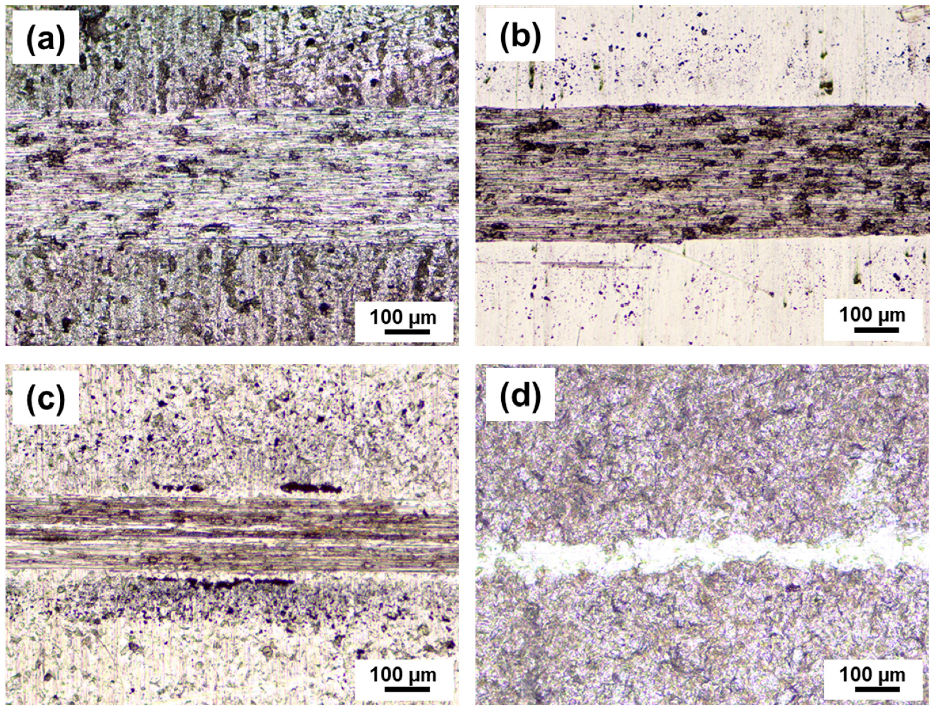
Figure 5 depicts optical microscope images illustrating the wear tracks that formed on the surfaces of the specimens following the tribotesting procedure. The wear morphology exhibited distinctive variations based on the specific contact conditions. With the exception of TCS, the wear tracks observed on the specimens appeared broad and featured numerous scratch marks. In contrast, the wear tracks on TCS demonstrated a relatively narrower width yet exhibited the greatest wear depth. This phenomenon is attributed to the likelihood of coating particles detaching from the surface [
28,
29].
To investigate the effect of sliding speed on friction and wear characteristics, an experiment was conducted at the sliding speed of 16 mm/s, which was four times the original sliding speed, while keeping other conditions constant. As illustrated in
Figure 6a, the friction coefficients for all specimens were tracked across sliding cycles. Specifically, PI and BI exhibited relatively elevated initial friction coefficients of 0.75 and 0.45, respectively, which then stabilized at 0.6 after 1000 cycles. In contrast, BS (Bare Stainless Steel) commenced with a low friction coefficient of less than 0.1 at the outset of sliding, gradually increased until 1000 cycles, and subsequently experienced a slight elevation, reaching 0.7. Remarkably, TCS (Teflon-Coated Stainless Steel) exhibited a constant friction coefficient of 0.08 at the sliding speed of 16 mm/s, demonstrating no fluctuation in friction coefficient throughout the entire sliding cycle.
Figure 6b shows the average friction coefficient values for each specimen, with BS registering the highest average friction coefficient at 0.64, followed by BI, PI, and TCS with values of 0.61, 0.6, and 0.08, respectively. Notably, TCS exhibited the lowest average friction coefficient of 0.08, representing an 88% reduction compared to BS. Overall, the friction coefficients at the sliding speed of 16 mm/s were lower than those at the sliding speed of 4 mm/s. As the sliding speed increased, the friction attributed to adhesive bonds between contacting interfaces diminished, leading to a reduction in friction coefficient owing to the augmented sliding speed [
30]. Additionally, it is recognized that friction coefficient declines as the contact area between the specimen and the counter tip decreases with increased sliding speed [
31]. Conversely, TCS exhibited consistent friction coefficient values irrespective of sliding speed, attributed to its robust inherent low-friction characteristics. Depicted in
Figure 6c are the wear rates across all specimens. BI exhibited the highest wear rate of 3.47 × 10
−7 mm
3/N·mm, whereas BS displayed the lowest wear rate of 0.87 × 10
−7 mm
3/N·mm. The wear rates for PI and TCS were 2.21 × 10
−7 mm
3/N·mm and 1.04 × 10
−7 mm
3/N·mm, respectively. Wear rates at the sliding speed of 16 mm/s were higher than those at 4 mm/s. The trend in wear rate variation with sliding speed exhibited an opposing aspect compared to the friction coefficient trend. Generally, multiple factors contribute to an increase in wear rate as sliding speed escalates. Higher sliding speeds entail renewed contact sliding, generating greater frictional heat residue from previous sliding contacts. Enhanced frictional heat leads to surface material softening and accelerated wear [
32]. Moreover, heightened sliding speed instantaneously disrupts adhesive bonding between the two contacting surfaces, hindering a rise in friction coefficient owing to adhesive forces. However, rapid collisions amid surface asperities can induce significant stress within the material, prompting deformation and fatigue-induced failure [
33]. Repetitive loading cycles encountered by contact areas during successive relative sliding at elevated speeds can induce microcracks, leading to surface fatigue and consequent detachment of wear particles, thereby accelerating wear [
34]. Consequently, as depicted in
Figure 7, a coarser wear pattern emerged at the sliding speed of 16 mm/s compared to the 4 mm/s condition. All specimens exhibited broader wear widths with numerous surface scratches. Notably, as the sliding speed increased, the friction coefficient of PI experienced marginal change, while the wear rate surged approximately sevenfold; for other specimens, friction coefficients decreased, and wear rates escalated by three to four times. PI, polished Inconel, characterized by minimal surface roughness and smoothness, showcased lower friction coefficients and wear rates than unpolished BI and BS at a relatively gradual sliding speed of 4 mm/s. However, at the accelerated sliding speed of 16 mm/s, PI’s friction coefficient remained comparable, while the wear rate increased significantly compared to BS. The smooth surface of PI is deemed significantly influenced by sliding speed. Additionally, TCS exhibited markedly low friction coefficients compared to other specimens, yet its wear rate was comparatively elevated. This discrepancy in TCS wear rate was attributed to the peeling of the Teflon coating due to repeated sliding friction, with the underlying stainless steel base material underneath the Teflon coating remaining protected. The friction coefficient and wear rate of TCS were comparatively less affected by the sliding speed change. During the tribotest spanning 5000 cycles, BI exhibited the highest friction coefficient and wear rate. Consequently, an extended experiment involving 10,000 cycles was conducted to assess the durability of the specimens. This extended experiment specifically included PI, BS, and TCS specimens, with the exclusion of BI for comparison purposes.
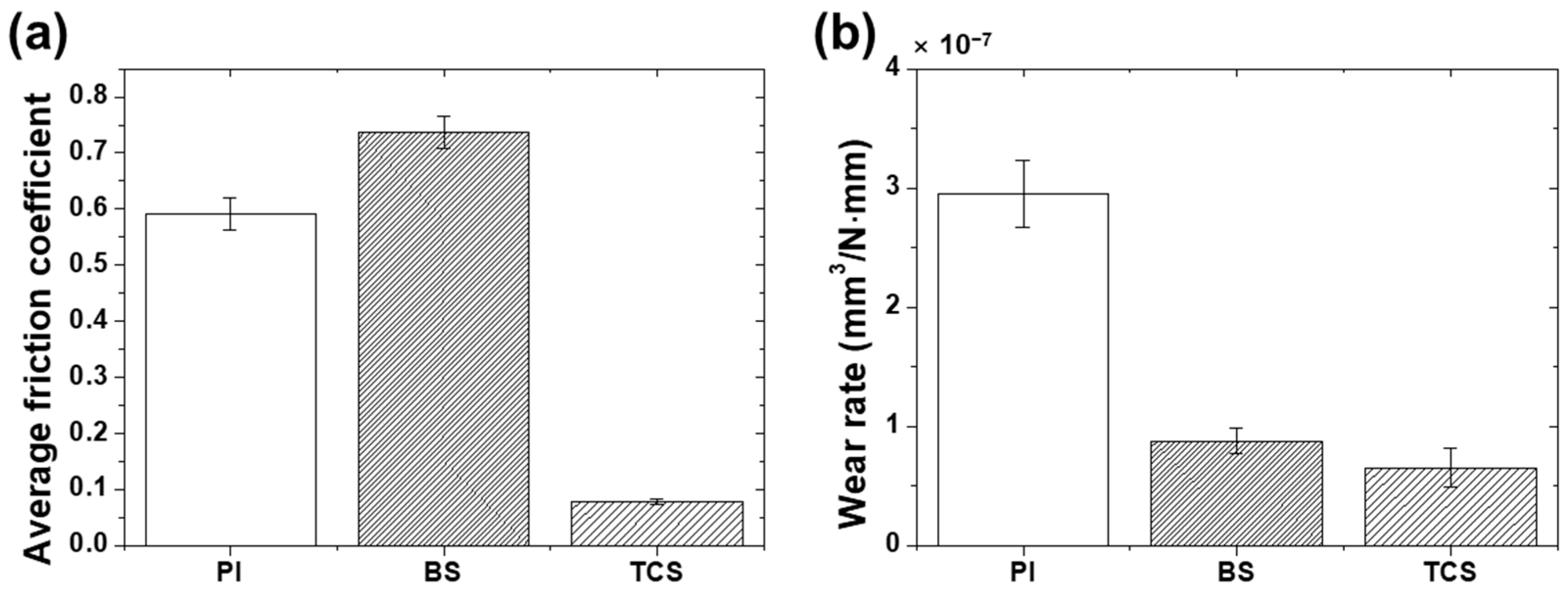
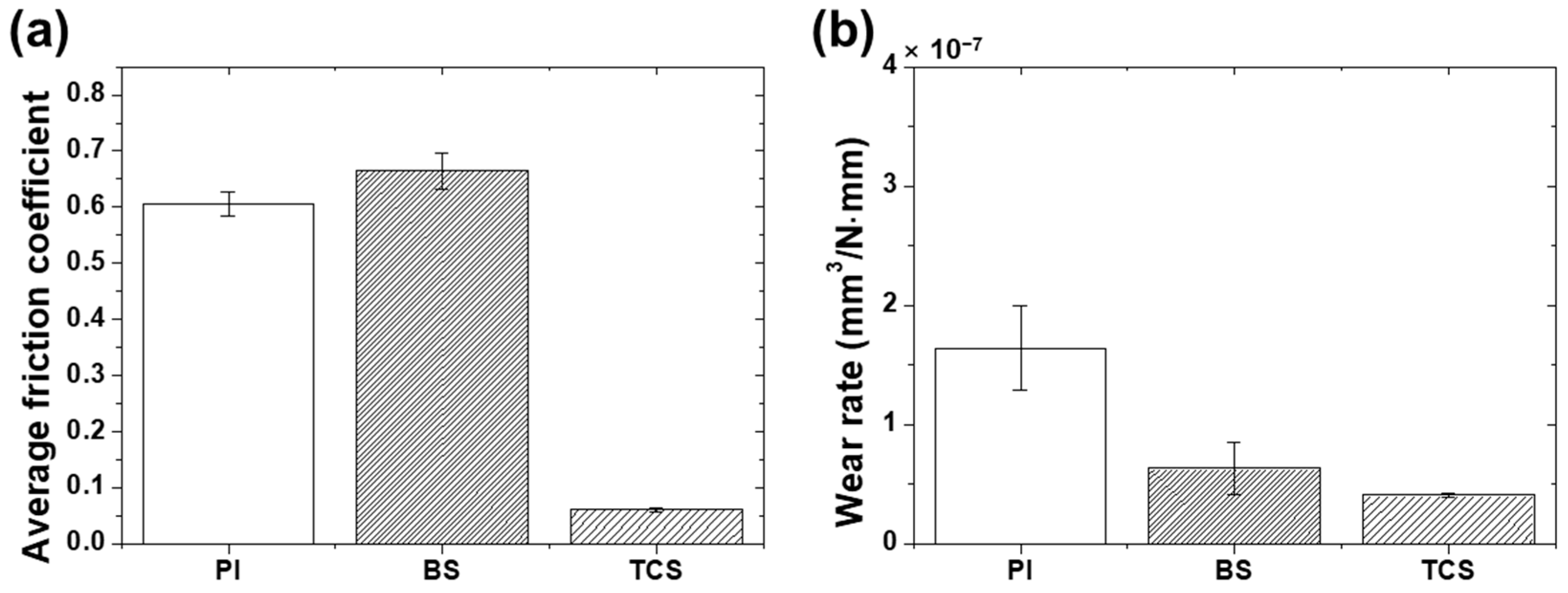
Figure 8a illustrates the average friction coefficients of the PI, BS, and TCS specimens subjected to a tribotest over 10,000 cycles under a normal load of 100 mN at a sliding speed of 16 mm/s. The TCS specimen demonstrated the lowest average friction coefficient of 0.08, whereas PI and BS exhibited friction coefficients of 0.59 and 0.74, respectively. The friction coefficient of PI remained comparable to that observed in the 5000-cycle experiment, whereas that of BS escalated by roughly 15%. As depicted in
Figure 6a, PI commenced with a low friction coefficient due to its meticulously polished surface but underwent rapid elevation during the initial cycles due to wear. Subsequently, it tapered off, stabilizing around 0.6 up to 5000 cycles. The experiments with extended sliding cycles displayed analogous trends, maintaining a friction coefficient of 0.6 up to 10,000 cycles. This signified that, following the initial rapid increase prompted by the impairment of PI’s smooth surface and the emergence of scratches, no substantial fluctuations in the friction coefficient occurred beyond 10,000 cycles following the surface conditioning process. Conversely, BS, characterized by a relatively coarse surface as depicted in
Figure 6a, commenced with a low friction coefficient, which gradually ascended. PI exhibited an average friction coefficient of 0.64, showing no notable deviation from that of PI. However, a pronounced fluctuation and a gradual upward trajectory were evident after 3000 cycles. The upward trajectory persisted in the experiment when extended to 10,000 cycles. In contrast, the augmented sliding cycles on the TCS specimen exhibited minimal influence on friction coefficients due to the inherent low-friction properties of Teflon.
Figure 8b presents the wear rates of the three specimens. PI exhibited the highest wear rate at 2.96 × 10
−7 mm
3/N·mm, whereas BS and TCS displayed wear rates of 0.88 × 10
−7 and 0.65 × 10
−7 mm
3/N·mm, respectively. In the 5000-cycle experiment, the relatively elevated wear rate was attributed to the inclusion of Teflon coating thickness into the wear rate calculation, following its detachment from TCS. However, a distinct trend emerged when the sliding cycle experiment was extended to 10,000 cycles. With increasing sliding cycles, the Teflon particles that peeled off adhered to the counter tip, leading to a shift in contact characteristics from hard contact mode to soft contact mode [
35]. Teflon-to-Teflon contact experiences lower contact pressure in comparison to metals, and the stress dispersion due to the cushioning effect of Teflon particles maintains low-friction/wear attributes [
36]. Consequently, it is plausible that TCS exhibited the lowest friction coefficient and wear rate.
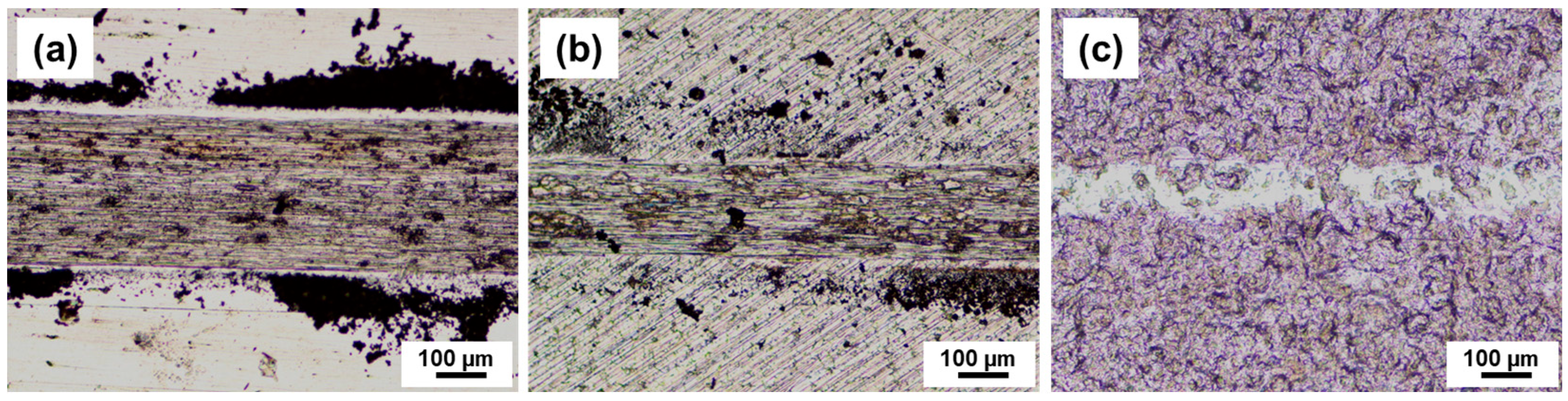
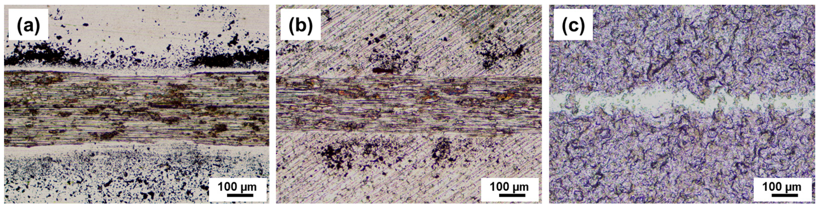
Figure 9 shows optical microscope images of wear tracks formed on the specimens through tribotests under 100 mN at 16 mm/s during 10,000 cycles. In line with the wear rate findings, PI exhibited the widest wear width, replete with numerous scratches at the center, and worn particles adhered around the wear track. BS displayed a narrower wear width compared to PI, yet numerous scratch-shaped morphologies were evident, and wear debris was adhered across the wear track. Conversely, TCS exhibited the narrowest wear width, coupled with the peeling of Teflon particles, with scratches only manifesting on select substrate parts.
Figure 10a depicts the average friction coefficient observed during the tribotest conducted under a normal load of 200 mN at a sliding speed of 16 mm/s over 10,000 cycles. Under the normal load of 200 mN, the contact pressures applied to PI, BS, and TCS were 772 MPa, 773 MPa, and 43.2 MPa, respectively. The average friction coefficients of PI and BS were 0.61 and 0.66, respectively, significantly surpassing that of TCS (0.07). The mechanism generating friction forces on each specimen in the high-pressure contact regime remained consistent with that observed under low loads. The lack of a substantial divergence in the friction coefficient in relation to the normal load suggests a direct proportionality between friction force and normal load. Consequently, it can be anticipated that the friction force resulting from a diaphragm micro-slip will escalate commensurate with applied pressure. Notably, surface roughness significantly influenced the friction coefficient, with smoother surfaces demonstrating lower friction coefficients. However, in the case of TCS, a consistently low-friction characteristic was sustained irrespective of the applied normal load. Furthermore, as depicted in
Figure 10b, TCS demonstrated the most minimal wear rate of 0.41 × 10
−7 mm
3/N·mm. This underscores the potential of applying a Teflon coating to the diaphragm plate surface to yield consistent frictional attributes. In contrast, PI (with a wear rate of 1.64 × 10
−7 mm
3/N·mm) and BS (with a wear rate of 0.63 × 10
−7 mm
3/N·mm) displayed reduced wear rates under high-load conditions (200 mN) compared to low-load conditions (100 mN), signifying their superior wear resistance characteristics in elevated load conditions. It is, however, worth noting that considering the lower wear rate of BS in comparison to PI, and the minimal wear rate exhibited by TCS, the superior durability of stainless steel 301 is evident. Consequently, stainless steel 301 and Teflon coating are deemed more appropriate materials for diaphragm plates. As shown in
Figure 11, the wear morphology formed in each specimen under a load of 200 mN was found to be analogous to that exhibited when only applying a normal load of 100 mN, while keeping the other experimental conditions constant. While the size of the wear track slightly increased, there were no significant differences in the damage morphology of the scratch marks caused by the relative sliding motion.
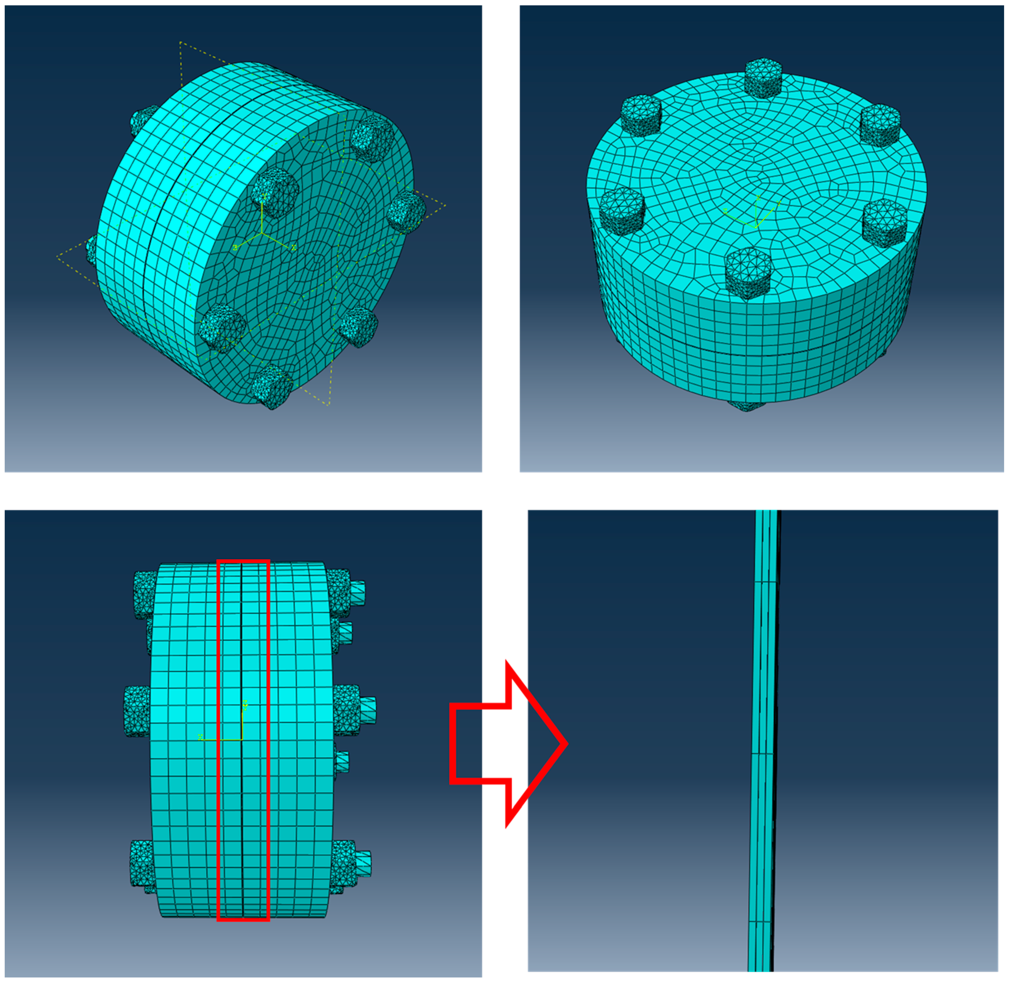
Finite element analysis (FEA) was conducted to assess the stress distribution within the diaphragm in response to the internal pressure variations of the compressor. As depicted in
Figure 12, the model encompassed the head section of the diaphragm compressor, incorporating the triple diaphragm plates, diaphragm fixation section, and deformation-affected chamber segment. The head cover possessed an inwardly curved surface, resulting in a void between its inner surface and the diaphragm. The void space’s height, representing the distance between the center point of the inner surface of the head cover and the diaphragm, was modeled as 3 mm, reflecting the maximum degree of diaphragm deformation. The diaphragm plates were simulated as circular plates with a diameter of 320 mm and a thickness of 0.4 mm. The configuration of the diaphragm incorporated three overlapping plates securely affixed through bolting. The triple diaphragm plates comprised the oil diaphragm, gas diaphragm, and middle diaphragm. The oil diaphragm resided on the side exposed to the actuating oil, the gas diaphragm was in contact with the gas, and the middle diaphragm was situated between the oil and gas diaphragm plates. Material properties derived from tensile testing were applied to the FEA simulation for both the head cover and diaphragm plates. To minimize the error in interpretation, the mesh of the diaphragm plate was densely constructed, and considering the circular shape of the diaphragm plate, the mesh was formed into a rectangular structure. Considering the joint between the head and diaphragm plate, it was fastened from the end of diaphragm plate towards its center up to 5 mm. The contact conditions between the inside of the head and diaphragm plate were determined using a surface-to-surface method, and pressure was applied to the entire surface of the oil diaphragm while in a state where diaphragm plate was fastened, inducing deformation in the diaphragm plate. The stress and deformation profiles of the head cover and diaphragm were analyzed as pressure was incrementally applied to reach 200 bar and 700 bar, respectively, followed by subsequent pressure release.
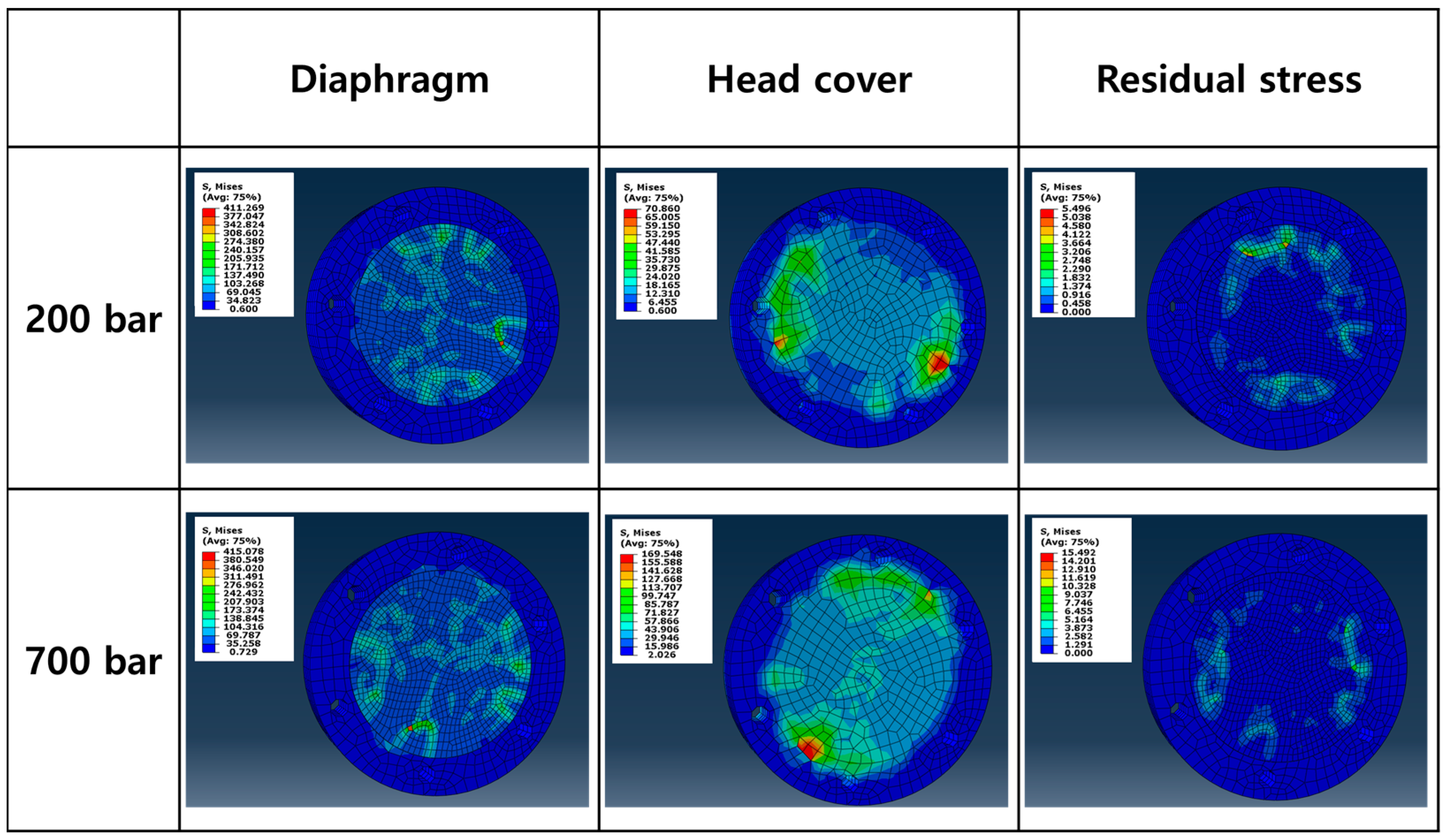
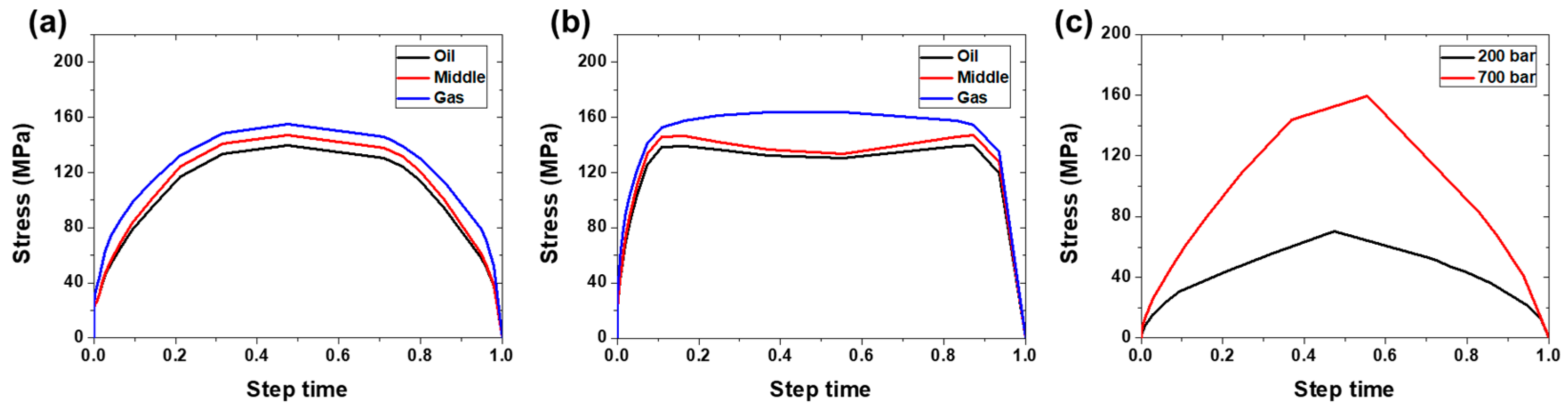
Figure 13 and
Figure 14 showcase the stress responses of the diaphragm and head cover under pressure conditions of 200 and 700 bar. The maximum stress observed under both pressure conditions ranged from 139 MPa to 163 MPa, with no notable distinction in maximum stress contingent upon the diaphragm plate’s location or pressure condition. However, for both pressure levels, the gas diaphragm experienced the highest stress, followed by the middle diaphragm and the oil diaphragm. This phenomenon is likely attributable to the bending of diaphragm plates in contact with each other under the pressure exerted on the oil diaphragm. Consequently, they convexly deformed toward the gas diaphragm and came into contact with the inner portion of the head cover of the diaphragm compressor [
37]. Under the 200-bar pressure, stress gradually increased and subsequently decreased over the same period of deformation. In contrast, under the 700-bar pressure, stress exhibited rapid initial increase, followed by a period of constancy, and concluded with a decrease concurrent with the pressure reduction. This discrepancy underscores the impact of pressure and deformation time on the diaphragm’s response. As pressure on the diaphragm escalated, the time required for stress increment shortened, leading to amplified contact pressure with the head cover. Additionally, the maximum stress applied to the head cover substantially rose with increasing pressure, reaching 70 MPa under 200 bar and 160 MPa under 700 bar. The dimensions and radius of the head cover, which accommodated space for diaphragm bending deformation, exerted notable influence on the extent of stress and deformation. As the void’s size increased, stress and deformation levels augmented. Nevertheless, there remained no marked variance in the degree of stress and deformation among diaphragms within head covers sharing identical radii [
12]. Consequently, the distribution of diaphragm stress was intrinsically influenced by gas pressure and head cover radius, necessitating post-treatment interventions to mitigate damage caused by contact with the head cover.
In this study, the friction and wear characteristics of Teflon-coated stainless steel 301 were observed to be superior. To determine the optimal coating conditions that exhibit the most favorable friction and wear characteristics, additional experiments considering various factors such as the temperature dependence of Teflon and P-V diagrams will be necessary. In particular, future research will likely require a comprehensive investigation into chemical, physical, and durability changes caused by environmental changes within a compressor during operation.


