1. Introduction
Metal cutting involves several physical and chemical phenomena [
1], which pose a challenge to its understanding and encourage the development of theoretical models to better understand the influence of input parameters on process performance. In this regard, the study of chip formation is a relevant issue, and the tool-chip contact mechanics have been investigated by a number of researchers, due to their influence on machining forces and tool wear. The friction coefficient is commonly used to characterize the difficulty of the chip sliding over the rake face and results mainly from adhesion and mechanical contributions, such as interlocking and plastic deformation.
Adhesion constitutes the connection at an interface between two solids when subjected to high pressure and constitutes a bonding phenomenon that occurs at the atomic level. It plays an important role in vacuum applications and when surfaces are very clean or not oxidized, as the higher surface energy in these cases promotes strong metallic bonds between them. This can occur in metal cutting, when the newly and chemically active formed chip surface contacts a smooth tool rake face. According to Maugis [
2], if contact surfaces are rough or contain contaminants, such as lubricants, adhesion is not expected to be relevant, and may not be verified at all. Maugis and Barquins [
3] reported that several experimental works demonstrated that immediately above a certain temperature (approximately 30% of the melting temperature), adhesion between metals grows sharply with its continuous increase and contact time.
Considering the complexity associated with the calibration of each contributing phenomena and their interdependence, general friction models have been proposed. The Amontons-Coulomb model of friction is the most used in metal cutting modelling and considers the relationship between tangential force (
) and perpendicular or normal force (
) to the rake surface as a measure of the resistance to chip flow. Equation (1) presents this empirical ratio from which a dimensionless number is obtained accordingly to the local tribological conditions and cutting parameters, designated as friction coefficient,
μ. This simplistic model does not take into account eventual effects of real and apparent contact areas changes on the average value of the friction coefficient. Nevertheless, for smooth and mirrored surfaces, the real contact area (
) tends to be similar to apparent contact area (
), and thus shear stress and normal stress at the contact interface can be estimated, as depicted in Equation (1). Usually,
μ assumes values lower than 0.3 for metal forming and 0.5 for metal cutting operations. This difference is related to the non-oxidized and chemically active metallic surfaces generated during cutting, while thin films of oxide covering workpiece (e.g., aluminum alloy) from billet to forged parts markedly decrease friction. A maximum theoretical value of 0.577 (for von-Mises yield criterion) or 0.5 (for Tresca yield criterion) for smooth and mirrored surfaces is necessary to tackle the computation convergence of stress fields. A maximum practical value is usually between 0.3 and 1 for ordinary surfaces (rough surfaces) but it can be greater than 1.
To encompass situations in which high contact pressures and adhesion take place, however, the Prandtl model is often used. It states that the frictional shear stress
τf is proportional to the material shear yield stress
k by a friction factor
mf (Equation (2)), which can assume values from 0 to 1. If the friction stress is higher than the shear flow stress of the workpiece the chip surface adheres to the rake face rather than slides against it, this is called sticking friction.
Zorev [
4] identified two different regions in the rake face: (i) a seizure or sticking region, closer to the cutting edge, where the frictional shear stress equals the material shear yield stress (
τf =
k), and (ii) a sliding region, where the friction behavior is described by the Amontons-Coulomb model. A hybrid model is considered when the Prandtl model with 0 <
mf < 1 is used in the sticking region. Shirakashi and Usui [
5] proposed a nonlinear exponential equation, which approximates the shear yield stress at high contact pressures, and Childs and Maekawa [
6] and Dirikolu et al. [
7] used an expanded model to include the friction factor and a work hardening exponent. Other contributions used the work material hardness instead of the shear yield stress [
8], modeled the behavior of the frictional shear stress in relation to the chip sliding speed [
9] and applied a polynomial fit to relate the frictional shear stress to the normal stress [
10]. Grzesik [
11] developed an approach to estimate the contribution of adhesion to the friction and Zhou [
12] took the stagnation layer at the sticking zone into account to obtain the friction coefficient.
Despite the different approaches to model the friction in the tool-chip interface and the criticisms related to the Amontons-Coulomb theory, investigations to determine a global (or apparent) friction coefficient, which corresponds to the ratio between tangential and normal forces, are still carried out due to their simplicity and the lack of consensus regarding more sophisticated models. Experimentally, several authors have noted that a global friction coefficient is affected by workpiece material and cutting tool characteristics, lubrication and atmosphere [
13,
14,
15,
16]. Current research has been dealing with nanofluids to improve cutting tribology, as reported by Huang et al. [
17], who demonstrated the benefits of adding graphene oxide and alumina to a water-based lubricant. The first element reduced the resistance to sliding and the second contributed to the formation of a tribo-layer that acted as a load bearer. Cristino et al. [
1] observed that conducting the cutting process in a controlled oxygen atmosphere results in higher values for friction coefficient, chip compression ratio and chip curl radius, as well as in a lower shear plane angle, in comparison to ambient conditions, suggesting that the occurrence of thin oxide films on chemically active metallic surfaces can affect chip formation.
Considering the stationary equilibrium of the chip, the geometric relationships developed by Merchant [
18], a null tool rake angle and a clearance angle large enough to prevent rubbing of the tool (clearance) with the machined surface, the global friction coefficient
μ in orthogonal cutting can be simply obtained by the relation between the measured thrust force (
Fp) and cutting force (
Fc). Thus, these values can be directly applied on Equation (1), where
Fp and
Fc are aligned with
Ft and
Fn, respectively.
The chip formation, at either macro- or micro-scales, is a complex multidisciplinary topic involving plasticity, ductile fracture, tribology, amongst other physico-chemical mechanisms. Its thorough understanding is not an easy task, since it requires dedicated diagnostics and simulations to overcome the difficulties in using conventional techniques, associated with the small spatial-scale in which chips form and slide over rake face, the overall high rate and temperature conditions, and the very high pressures and deformations involved. Moreover, the chip detaches from the rake face at a tangential direction, making it extremely difficult or even impossible to accomplish the contact interface mechanics. The tool-chip contact length is possibly the most difficult parameter to accomplish. In this regard, the present paper proposes a method to better determine the influence of the contact length on forces, stresses and friction coefficients during orthogonal cutting tests. In addition, the effect of the surrounding medium on the global friction coefficient is investigated. For this, adapted cutting tools were prepared and applied in the cutting of different materials.
2. Materials and Methods
Orthogonal cutting tests were carried out using an orthogonal metal cutting apparatus under different controlled atmospheres (ambient conditions, oxygen and argon), with a flexible gas chamber mounted around the workpiece and cutting tool. The chamber was assembled to ensure its proper sealing and a flow meter was connected to gas cylinders to control the inner atmosphere surrounding the experiments. Parallelepiped test specimens, with 15 mm, 15 mm and 1.4 mm of length, height, and thickness, respectively, were made of strain hardened aluminum alloy AA1085 (compressive strain of approximately 1.25 after annealing) and annealed pure copper UNS C12000. The test specimens were mounted using a suitable device directly on a load cell, that allows measuring cutting force and thrust force. The electrical signals were obtained at an acquisition rate of 500 Hz through a DAQ board and a National Instruments USB-9162 amplifier connected to a computer with the Labview 8.5 software, which enabled the conversion of the electrical signal to force values after the calibration procedure. A schematic representation and images of the experimental apparatus are shown in
Figure 1.
The orthogonal cutting tests were carried out with the straight edge of triangular cemented tungsten carbide cutting inserts ISO grade K10, with clearance angle
α ≅ 6.5° (to avoid the influence of the contact between the tool clearance face and the machined surface on the measured forces) and rake angle
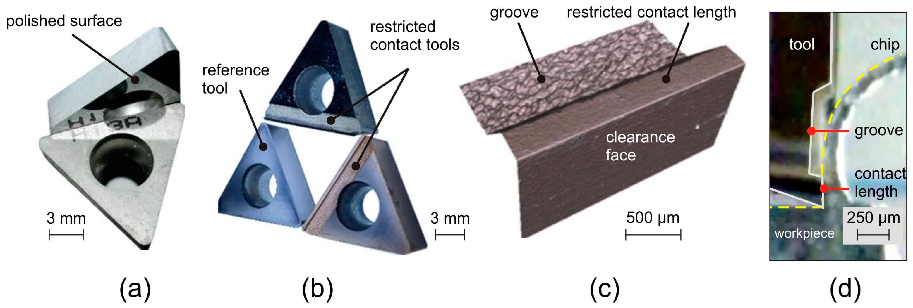
γ = 0°. All the inserts had their rake and clearance faces polished (
Figure 2a) through diamond abrasive pastes with granulometry from 7 µm to 0.5 µm, which allowed achieving an average roughness
Ra ≅ 0.01 µm (in all faces) and an edge radius
rβ ≅ 1 µm (at the straight edges).
In order to restrict the tool-chip contact length, grooves were produced by laser machining at different distances from the cutting edge on the rake faces of some inserts (
Figure 2b). This means that the tool-chip contact interface is limited from the edge to the beginning of the groove. Two different restricted contact lengths were manufactured: with 60 µm (LC60) and 240 µm (LC240). For comparison purposes, a cutting insert without a groove (reference tool, RT) was also applied.
The grooves were produced on a DML40SI machine tool from Deckel Maho Gildemeister (DMG). The required energy for the laser beam is provided by a continuous Nd:YAG laser with Q-switch to control the pulsed laser frequency and the respective laser intensity. The main operative parameters that can have been controlled were the percentage of the current intensity that passing through the lamp, I (%), the Q-switch opening frequency, f (kHz), and the laser feed rate, v (mm/s). After an optimization procedure [
19], the cutting parameters were kept constant at 50%, 30 kHz and 150 mm/s for the current intensity percentage, opening frequency and laser feed rate, respectively.
The cutting experiments were designed in order to analyze the influence of (i) gas shields (active and inert) and (ii) tool-chip contact length on the cutting and thrust forces, and the friction coefficient values. Materials selection was conducted for complementary results, using technically-pure metallic alloys with different physical, chemical and mechanical properties.
Dry orthogonal cutting tests were performed combining two types of cutting tools: the reference tool (without modifications on the rake face) and the restricted contact tools (with grooves on the rake face in order to restrict the tool-chip contact length). These different tools were applied in combination with a wide range of uncut chip thicknesses (h), from 10 µm to 100 µm. The uncut chip thicknesses were programmed in the orthogonal metal cutting apparatus through a numerical control and the real thicknesses of removed material were controlled by a dial indicator, the corrected values having been used in the graphs. This procedure allowed correlating the output variables with real uncut chip thickness values, avoiding the influence of positioning errors of the machine. Due to the limits of the apparatus and the workpiece geometry, the cutting speed vc = 45 mm/min and the depth of cut ap = 1.4 mm were kept constant. Due to the very low cutting parameters applied in the tests, no tool wear was detected during the experiments. Thus, it could be neglected.
A proper combination of the uncut chip thickness
h and the restricted contact length should consider the chip formation in order to avoid double contact of the chip with the tool after its passage over the groove (
Figure 2c,d), influencing the process forces. This was performed as the basis on the preliminary tests.
Because the cutting experiments were performed at room temperature under very low cutting speeds, it was not necessary to consider the influence of temperature and strain rate sensitivity in the tests. This was important because it eliminated the combined effect of process variables that could eventually mask the influence of individual parameters.
3. Results and Discussion
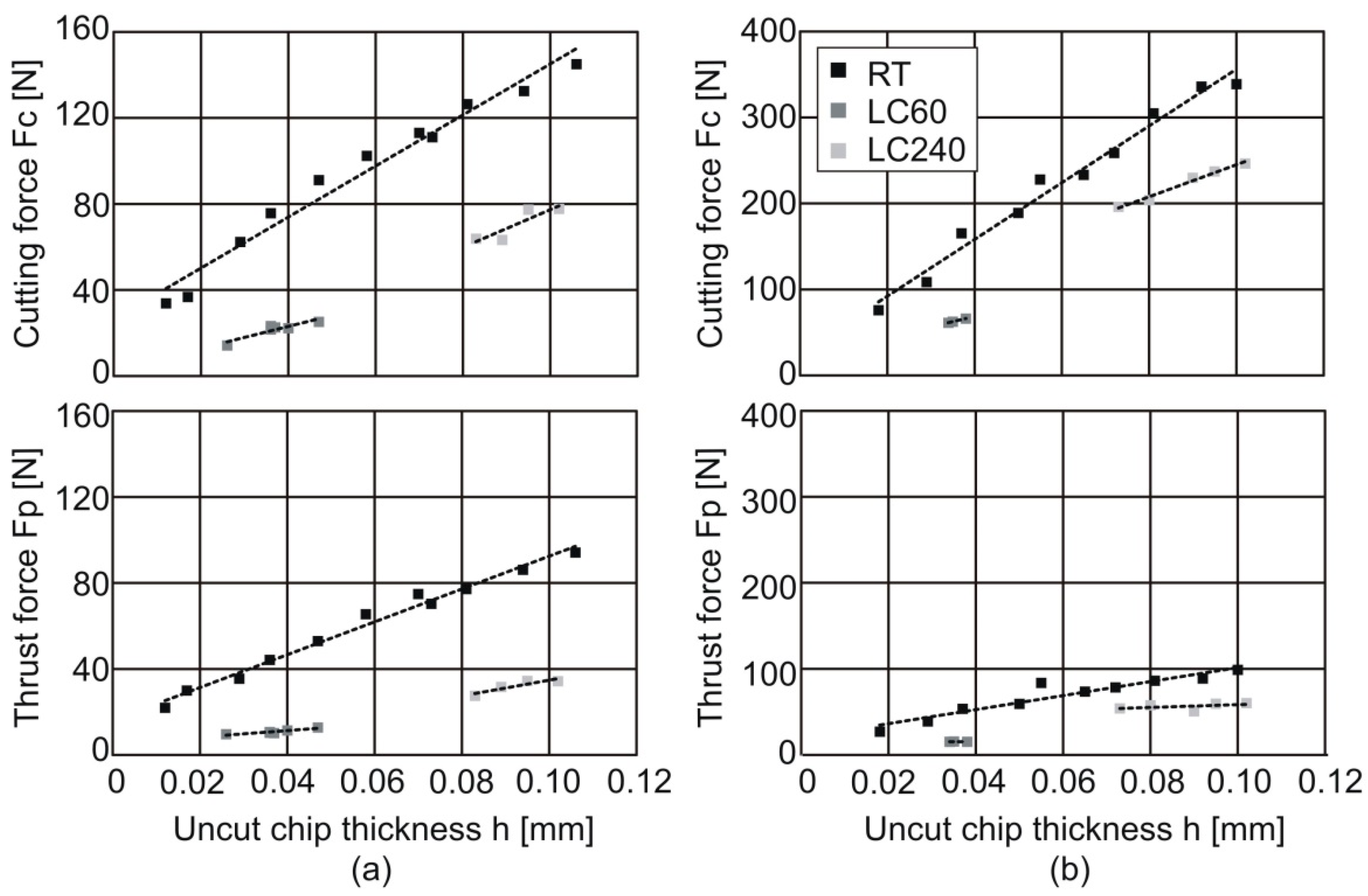
Figure 3 shows the measured cutting and thrust forces as a function of the uncut chip thickness for different test materials under an inert argon atmosphere. This inert surrounding medium was initially chosen to avoid chemical effects close to the tool-chip contact region [
16] that might hamper a proper monitoring of the cutting load and sound understanding of the friction mechanism. In comparison to the strain hardened aluminum alloy, higher cutting and thrust forces are recorded for the annealed pure copper, due to its higher mechanical properties. Additionally, an increase in the force components is observed for both materials as the uncut chip thickness is increased. However, different levels and trends were found for tools with distinct contact lengths. The experimental measurements using the reference tool (RT) allows the determination of an upper limit for the cutting and thrust forces. Such upper limits are specific of the tribological conditions (i.e., argon atmosphere). By contrast, under oxygen concentration such upper limits would perform differently.
Figure 3 also shows that adapted cutting tools with restricted contact length (LC) promote lower cutting load values, compared with that of the reference tool. As expected, the cutting loads increase with the fixed contact length value of each adapted cutting tool (i.e., LC60 for 60 µm and LC240 for 240 µm), since a larger contact length requires a thicker uncut chip thickness (i.e., each specific tool is limited in a specific range of the uncut chip thickness). Yet, and despite the linear relation between cutting load and uncut chip thickness, the linear fitting of each set of experimental tests are not collinear, different growth rates occurring due to the distinct contact areas, which affect the difficulty of chip flow.
Considering that the process forces were measured during the experiments and the tool-chip contact area can be calculated by multiplying the restricted contact length in each case by the width of cut, the stresses on the rake face could be obtained. An analysis of the normal and frictional shear stresses at the tool-chip interface can be performed when the contact geometry is assumed to be perfectly known, complementary contributions can be neglected and stick-slip oscillation is minimal. The combination of restricted contact tools and mirrored surfaces under inert surrounding medium fulfills the ideal to which the real contact area approaches the apparent contact area for the steady state orthogonal metal cutting model.
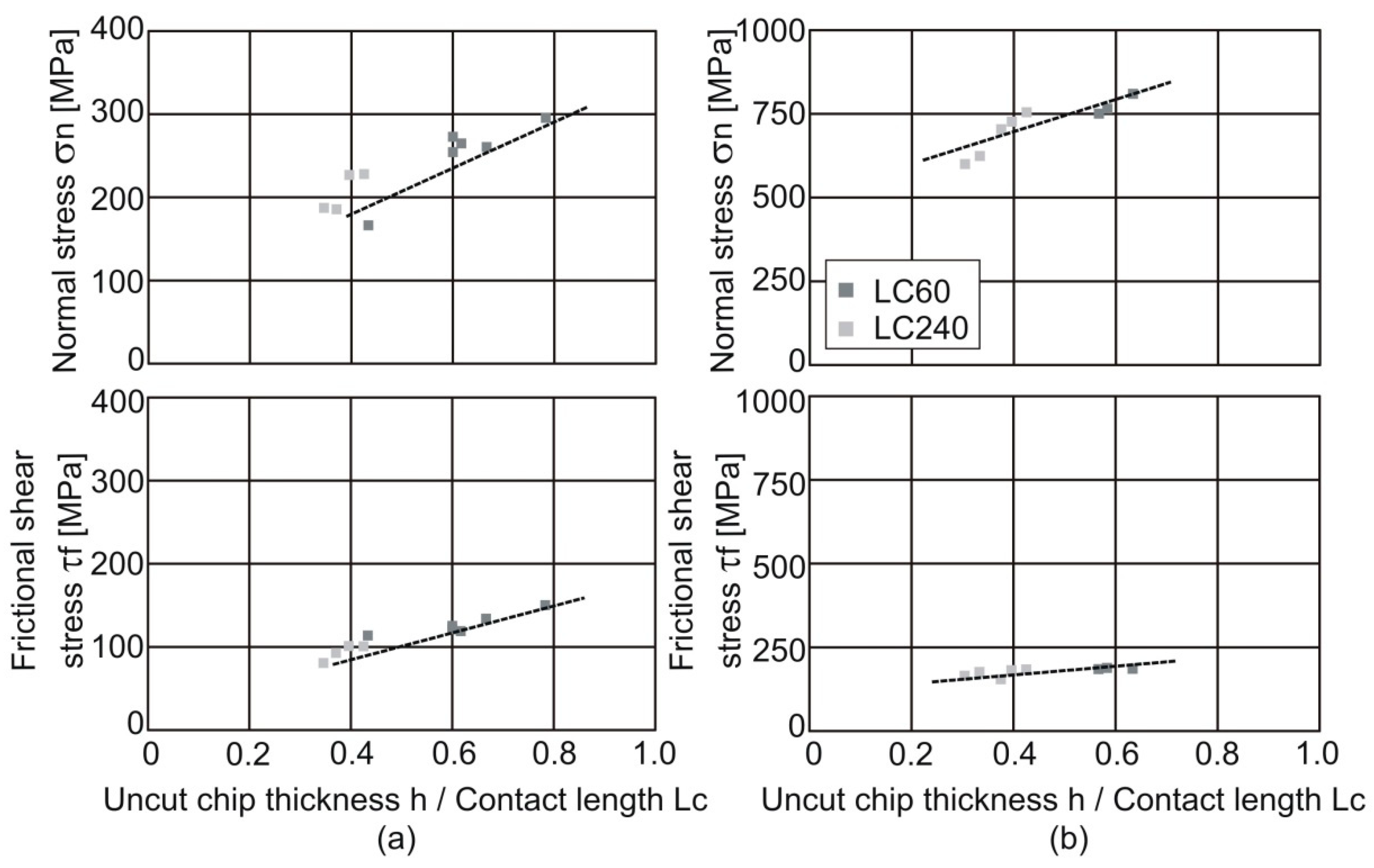
In the proposed experiments, to avoid subsequent contact between the chip and the tool, tools with different contact lengths could only be applied in a specific range of uncut chip thickness values. Thus, in order to normalize the data for the different conditions, the stresses were plotted against the ratio between the uncut chip thickness and the restricted contact length, h/LC.
Figure 4 shows that the uncut chip thickness promotes higher forces, but without changes in the apparent contact area (restricted contact tools). Thus, higher stress components occur due to the increased material volume that passes through the shear plane and undergoes considerable plastic deformation to form a continuous chip. Otherwise, higher chip thickness increases the tool-chip contact area in order to better distribute the cutting load over a larger area, thus limiting the overall increase in stresses.
Bearing the hypotheses of the orthogonal cutting theory in mind, the global friction coefficient can be obtained by relating the measured thrust and cutting forces, considering their correspondence to the friction and normal forces at the rake face (since the rake angle
γ = 0°), respectively. Graphically, it can be noted that the linear regressions of the experimental data obtained using the reference tool and adapted tools are close (
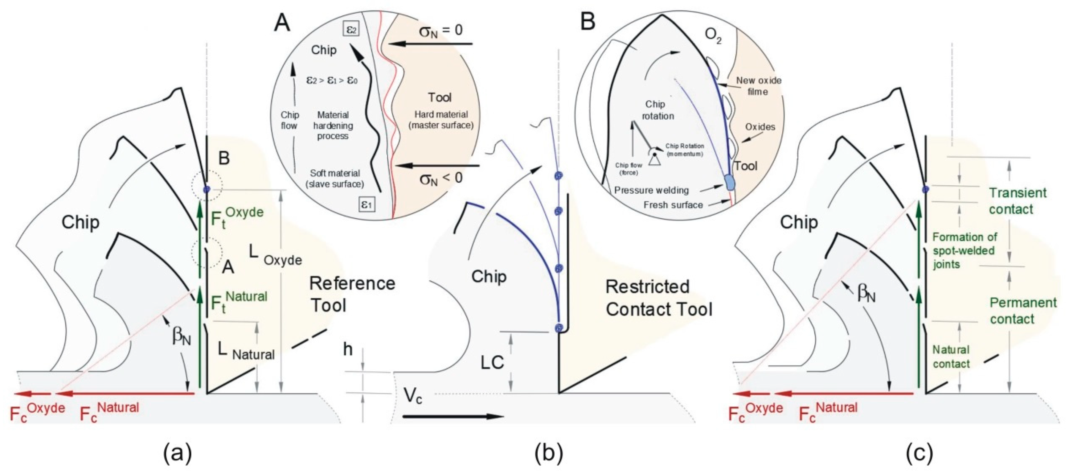
Figure 5), although a slightly steeper slope is observed for the reference tool, which can be attributed to the simultaneous occurrence of two different tribological conditions at the tool-chip interface: closer to the cutting edge, the chip is completely in contact with the tool, which is being called “permanent contact”. In a second part, closer to the point where the chip detaches from the rake face, the normal stress approaches zero, the actual contact area becomes smaller than the apparent contact area, but a friction force still exists. This region is being called “transient contact”. The combination of both tribological conditions results in an exclusive increase in the friction force, which after promotes the global friction coefficient. Differently, only the permanent contact occurs for the tools with restricted contact lengths, independently of the prepared length, thus explaining the lower value of the friction coefficient in this case. Both for forces and stresses, a directly proportional relation between the normal and tangential components over the rake face was found. As a result, the Amontons-Coulomb theory could still be applied.
It is worth noting that the normal and frictional shear stresses measured in the rake face present a severe stress state for both materials. Under these extreme conditions, a stick-slip effect should be expected based on the Tresca yield criterion. Critical shear stresses obtained from uniaxial compression tests of 80 MPa and 210 MPa can be approached for AA1085 and UNS C12000, respectively. Yet, the estimated average values for frictional shear stresses over the rake face are 150 MPa and 200 MPa for the same tested materials. However, it was noted from the experiments that no build-up occurred, and the chip slid freely under steady state regime over the rake face.
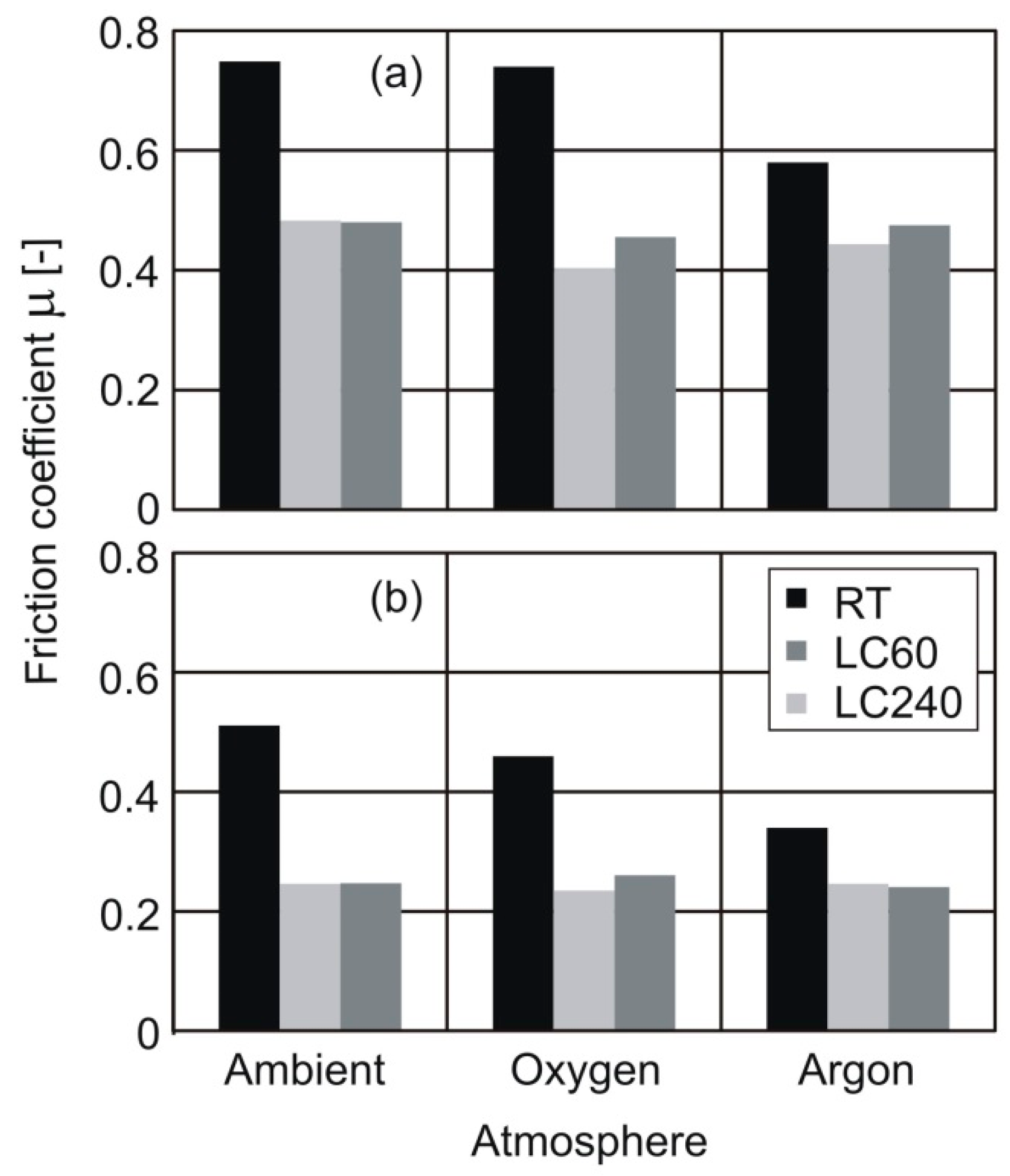
When only permanent contact occurs, as in the case of restricted contact tools and normal stress can be assumed constant over the whole rake face, it can be stated that the global friction coefficient is independent of the contact area, since friction and normal force components are normalized by the same value. Furthermore, different global friction coefficients were obtained for the strain hardened AA1085 and annealed UNS C12000: approximately 0.63 for the former and 0.30 for the latter when the reference tool was used and 0.47 and 0.25, respectively, when the tools with restricted contact length were applied.
Considering the particular tribological conditions of metal cutting and the affinity of the elements present in the surrounding medium with those in the workpiece and tool materials, the occurrence of chemical reactions that alter the tribological conditions are expected. Therefore, cutting tests in inert and active atmospheres were carried out to investigate their influence on the global friction coefficient, the obtained results being demonstrated in
Figure 6. For both the strain hardened aluminum alloy and the annealed pure copper, a higher global friction coefficient is observed for the reference tool in comparison to the tools with restricted contact length, between which no significant differences are noted, even in different atmospheres.
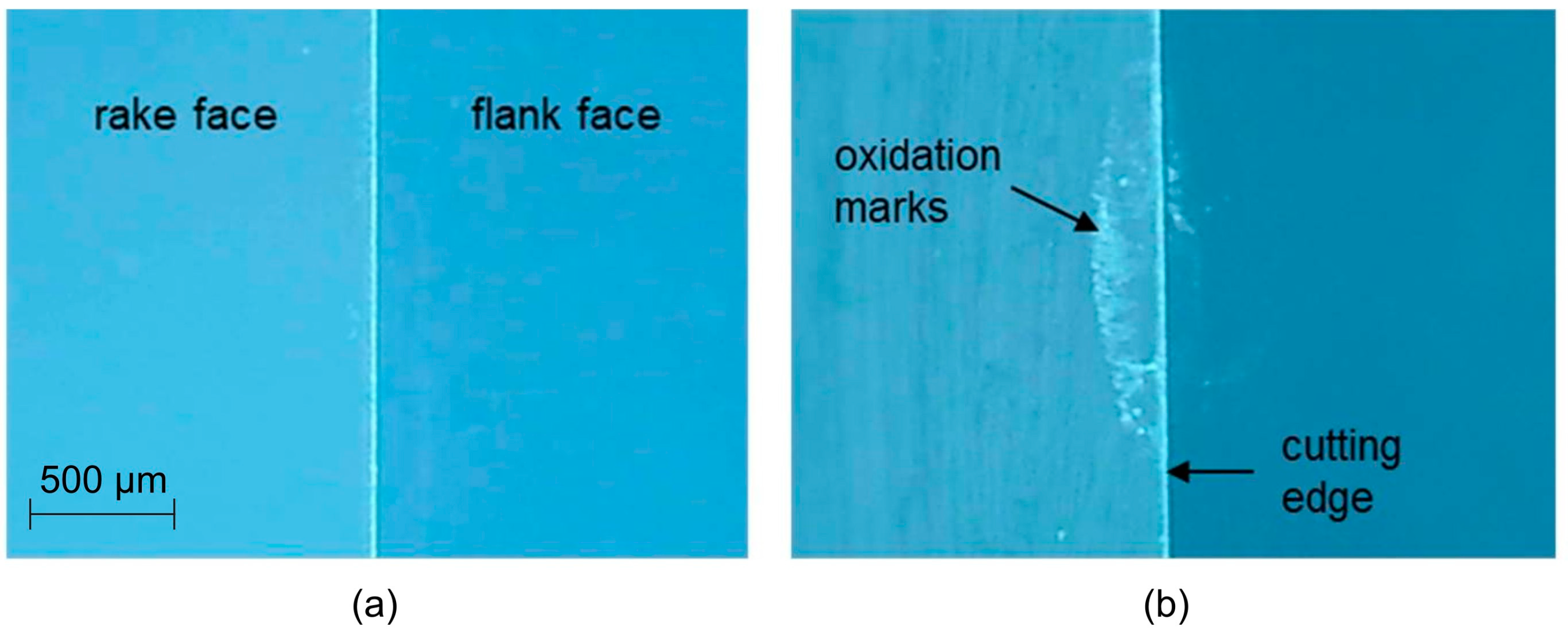
Figure 7 shows the aspect of the rake face of the reference tool before and after cutting the aluminum alloy in ambient atmosphere. Comparing both images, evidence of the previous explanations can be provided. White oxidation marks can be seen next to the border of the tool-chip contact length in the tool rake face after cutting (
Figure 7b), while a very smooth surface is observed before (
Figure 7a). Still considering the image obtained after the experiment, it can be observed that closer to the edge, there is no oxidized layer or adhesion of workpiece material, which reinforces the applicability of the Amontons-Coulomb theory to obtain the global friction coefficient.
The reason for a higher global friction coefficient when cutting with the reference tool, even in inert gas atmosphere, has been given before. However, even higher values in ambient and oxygen atmospheres must be discussed. In both cases, the presence of oxygen generates oxide layers in the free surfaces, which contribute to the formation of spot joints between chip and tool rake face and act as a third body after being released (
Figure 8a), thus increasing the friction coefficient, as reported by [
1]. Details on
Figure 8 also illustrate the material strain hardening due to interlocking mechanisms and chemical reactions between the freshly cut surface and the cutting tool, both of which contribute to the energetic dissipation. Differently, in tools with restricted contact length, the oxide films are formed outside the limits of the tool-chip contact region, but inside the grooves (
Figure 8b), not affecting the coefficient of friction. Therefore, no significant variation in the global friction coefficient is noticed in these cases.
Figure 8c illustrates the permanent and the transient contact regions, as previously discussed.
4. Conclusions
This paper reexamined the influence of the contact area in the tribology of chip flow by performing orthogonal metal cutting tests using restricted contact tools. This research deviates from classical analysis of frictional contact between chip and tool to focus on the stresses at the tool–chip contact interface that arise from the combination between the restricted contact area and polished surfaces under active and inert gas shields. Under these well-controlled experiments, it was possible to better understand how energy dissipates as the chips slide over the rake face.
The experimental results showed that restricted contact tools provide better control of the frictional and normal forces as well as their respective growth rates as uncut chip thickness changes. Despite the high values estimated for the tool-chip frictional shear stress, no stick-slip oscillations and material build-up have been observed, and chips slipped freely over the tool rake face under steady state regime. Moreover, a directly proportional relation between the normal and tangential components over the rake face allows the Amontons-Coulomb model of friction to be used.
Cutting under active and inert gas shields allows conclusions to be drawn on the two distinct tribological conditions at the rake face when using unrestricted contact tools. A first region close to the cutting edge where well-established contact interface takes place under extreme hydrostatic and deviatoric stresses (normal and tangential to rake face). A second region is further ahead at the point where chip slides and progressively detaches tangentially from the rake face near null normal force, but where a non-null tangential force contact is expected. This second region can extend over the rake face as the uncut chip thickness rises in order to distribute the forces over a larger area, limiting the overall increase of stresses, but adversely affecting friction. On the contrary, restricted contact tools eliminates tangential contact under low pressure as chip slides over the rake face and avoid the formation of spot-welded joints by oxidation at the point where chip detaches from the cutting tool (oxidation occurs after). The restricted contact tools exclusively involve the well-established contact interface of the first region, thus promoting a lower global friction coefficient and cutting loads, and reduced sensibility to the active atmospheres.

