Article

An Investigation of the Sequential Micro-Laser Drilling and Conventional Re-Drilling of Angled Holes in an Inconel 625 Ni-Based Alloy

by
Krzysztof Szwajka
1,
Joanna Zielińska-Szwajka
2,
Krzysztof Żaba
3,* and
Tomasz Trzepieciński
4
1
Department of Integrated Design and Tribology Systems, Faculty of Mechanics and Technology, Rzeszow University of Technology, ul. Kwiatkowskiego 4, 37-450 Stalowa Wola, Poland
2
Department of Component Manufacturing and Production Organization, Faculty of Mechanics and Technology, Rzeszow University of Technology, ul. Kwiatkowskiego 4, 37-450 Stalowa Wola, Poland
3
Faculty of Non-Ferrous Metals, AGH University of Science and Technology, al. Mickiewicza 30, 30-059 Krakow, Poland
4
Department of Manufacturing Processes and Production Engineering, Rzeszow University of Technology, al. Powstańców Warszawy 8, 35-959 Rzeszow, Poland
*
Author to whom correspondence should be addressed.
Lubricants 2023, 11(9), 384; https://doi.org/10.3390/lubricants11090384
Submission received: 23 July 2023 / Revised: 1 September 2023 / Accepted: 5 September 2023 / Published: 8 September 2023

Abstract

:
The conventional (mechanical) micro-drilling of Inconel 625 alloys suffers from premature breakage of the drill bit due to its brittle nature and limited cutting tool life. Even greater problems are encountered when micro-drilling holes at an acute angle to the machining plane. In such a process, there are great difficulties associated with the low stiffness of the tool, which leads to the frequent breakage of the drill during machining. Therefore, in this type of mechanical drilling operation, the hole surface is usually milled with an end mill to provide a flat surface on the entry side of the drill bit. The aim of this article is to recognise the process of sequential micro-drilling and to assess the possibility of its use as an effective and efficient method of micro-drilling in hard-to-cut metals. The paper describes the process of initial laser drilling followed by final mechanical micro-drilling. Inconel 625 Ni-based alloy sheets were used as the test material. The shape and microstructure of pre-holes made with a laser, the volumetric efficiency of laser processing, the energy in the mechanical drilling process, and tool wear were analysed. The research results show that in the sequential drilling process, mechanical re-drilling eliminates the geometrical discrepancies resulting from the laser pre-drilling. In addition, it was found that, compared to mechanical micro-drilling, the use of sequential micro-drilling resulted in a two-fold increase in drill life. It has been also observed that sequential machining reduces the energy demand by 60% compared to mechanical micro-drilling. In addition, it was found that the edge of the drill bit is a key factor in deciding the target diameter of the laser-drilled pilot hole, and thus in selecting the micro-drilling parameters.

1. Introduction

Drilling micro-holes in metal materials encounters many technological problems that result from the high strength of these materials and the need to select a tool with appropriate thermal and mechanical strength, and the selection of the appropriate coolant and cutting conditions. The inappropriate selection of these parameters results in excessive tool wear and deterioration of the quality of the hole surface [1]. Stainless steels and nickel alloys, due to their physical and mechanical properties, that is, high strength and high fatigue resistance, are particularly difficult to machine [2,3]. They require tools with high strength, and these requirements increase as the diameter of the drill bit decreases. Increased tool life is achieved by using anti-wear coatings on the tools and the use of cooling and lubricating liquids [4,5]. In current industrial practice, cutting fluid is conventionally used as a cooling medium, but the cost of cutting fluid accounts for 20% of the total manufacturing cost [6]. To prevent the excessive use of cutting fluids, electrostatic minimum quantity lubrication (MQL) [7], micro-lubrication [8], and dry or near-dry manufacturing technologies [9] have emerged. When cutting stainless steel, using green cutting technologies, AlTiN-based coated tools showed an advantage over water and oil conditions [10]. The implementation of MQL is considered to be clean lubrication technology as this minimises the consumption of cutting fluid [11].
An alternative method for making holes in a wide range of materials (glass, metals, composites, ceramics, wood) is laser processing. Laser micro-processing enables micro-drilling and micro-cutting with an accuracy of 1–2 µm. Diode pumped solid state (DPSS) lasers and excimer gas lasers [12] are used in machining applications. DPSS lasers generate radiation with a wavelength of 106 nm and, with the help of additional crystals (i.e., barium borate [BaB2O4], lithium triborate [LiB3O5]), it is possible to obtain wavelengths of 532 nm and 355 nm. Excimer lasers generate ultraviolet radiation in the range of 193–350 nm. Commercially available lasers are manufactured in a wide range of wavelengths, pulse durations, and beam powers. Laser cutting is characterised by a small heat-affected zone (HAZ), a narrow cutting gap, and therefore less material loss, and a small amount of heat input, as well as low internal stresses after processing [13]. The size of the HAZ can be reduced by the use of femtosecond lasers. The advantages of laser micro-drilling compared to conventional drilling are the lack of lubrication and that there is no metallic contact between the tool and the workpiece, thus ensuring repeatability of the machining [14,15].
The need for micro-holes with a cross-sectional area of less than 2 mm2 in difficult-to-cut Ni-based alloys is highest for cooling channels in the aerospace industry. Ni-based superalloys, commonly named Inconels, are used in many areas, such as the aerospace (jet engines), nuclear power, and automotive (turbo chargers) industries [16,17].
Although conventional drilling techniques such as mechanical micro-drilling produce high-quality holes, the main problems are premature drill breakage and drilling holes at acute angles, especially in the case of very small holes. The other advantage of mechanical drilling is that the electrical properties of the workpiece do not influence the process. Venkatesan et al. [18] experimentally investigated the drilling of micro-holes on Inconel 718. They analysed the effects of the spindle speed, feed rate, and cutting tool diameter on the thrust force, temperature, and material removal rate (MMR), and found that the MMR increases with increasing spindle speed and feed rate. Kivak et al. [19] studied the changes in the wear of the cutting tool and the hole circularity when drilling on Inconel 718. They concluded that the circularity of the drilled hole was most affected by the feed rate. Imran et al. [20] investigated the effect of the tool geometry on tool wear and burr formation during micro-drilling on an Inconel 718 alloy. They found a clear correlation between the bit geometry and tool wear. Imran et al. [21] investigated the effect of the feed rate and spindle speed on the tool wear when micro-drilling an Inconel 718 alloy. Sager et al. [22] studied the effects of the cutting parameters on the tool wear and hole circularity when drilling an Inconel 625 alloy. It was found that the feed rate led to a significant increase in the thrust force. The feed rate and cutting speed were found to be the dominant parameters of the mean surface roughness of the drilled holes. Attanasio [23] conducted tool life tests when micro-drilling hard-to-cut alloys, such as Inconel 625, Hastelloy C22, and 310H stainless steel. They utilised a peck drilling strategy and found that the workability of test materials at the microscale is mainly affected by the material’s ductility rather than its hardness.
Li et al. [24] used laser beam machining to micro-drill holes in fuel injection nozzles. The results revealed that the hybrid process (laser and electrical discharge machining—EDM) increased the production capacity by 90% compared with EDM drilling. Brown [25] investigated the mechanical drilling of shaped holes in turbine airfoils. The laser was used to pre-drill the hole and then the hole was finished by high-speed ball end milling. Khanafer et al. [26] used MQL-nanofluid during the micro-drilling of Inconel 718. The performance of the drilling process was investigated with regard to burr formation and tool wear. It was found that MQL drilling is a promising technology in terms of sustainability. Ceritbinmez et al. [27] drilled Inconel 625 using mechanical and thermal techniques. They found that the thermal drilling methods formed a white layer with a thickness of 20–50 μm in the cross-section of specimens, while no white layer was formed in conventional drilling. Agrawal et al. [28] proposed a theoretical model to predict tool wear when micro-drilling Inconel 718 to evaluate the tool life of TiAlN- and TiAlSiN-coated drills. The results of the micro-drilling experiments showed that the coatings increased the life of the drills compared to uncoated drills. Primeaux et al. [29] investigated the performance of micro-drilling Inconel X-750 using TiAlN-coated and uncoated WC/Co drills. They analysed the geometry of the drilled holes and the tool life. A slight reduction in the variation of the hole geometry of the TiAlN-coated tool was observed. Moreover, the adhesion of the workpiece material to the drill bit revealed the high temperature of the micro-drilling process. Kiswanto et al. [30] studied the effect of the spindle speed (up to 10,000 rpm) and feed rate on the surface roughness of holes micro-drilled in Inconel 718 material. It was found that the higher the spindle speed, the smaller the surface roughness. Nair [31] attempted to improve the performance of the sequential micro-drilling of Inconel 718 material. The effect of key process parameters on the tool life was analysed using a Taguchi experimental design. It was found that a pilot hole reduces the tool wear. Imran et al. [32] studied the deep-hole micro-drilling performance in the processing of the CMSX4 Ni-based alloy. It was concluded that controlling the relative geometry of the pilot hole to the twist drill is critical. Chen and Liao [17] investigated the wear mechanisms of a TiAlN-coated tool when drilling Inconel 718 material. It was found that the coating layer was gradually abraded away, which increased the thrust force and intensified the friction force. Venkatesan et al. [33] drilled micro-cooling holes in turbine blades made of Inconel 625 alloy. The effects of the feed rate, spindle speed, and the diameter of the micro-drill on the circularity errors, cylindricity, and hole diameter were examined. They found that 0.8 mm is the most suitable tool diameter for achieving hole quality in micro-drilling applications. The work of Azim [34] focused on the machinability of Inconel 825 in micro-drilling operations. He studied the effect of micro-drilling parameters on the circumferential damage and surface profile of micro-holes. He concluded that the surface roughness of the surface of the holes increased with increases in both feed rate and cutting speed. Khadtare et al. [35] drilled micro-holes at different orientations on an Inconel 718 alloy. The experiments were performed under a dry environment with a 100 μm pecking length. They found that a higher tool life was observed in straight-hole drilling at a combination of a low feed rate and a low spindle speed. Kwong et al. [36] investigated the tool-workpiece interactions during the drilling of RR1000 Ni-based superalloy. They concluded that the increased material drag associated with a worn tool resulted in compressive hoop surface residual stresses near the entrance hole. Venkatesan et al. [37] optimised the micro-drilling parameters and geometrical accuracy in drilling on an Inconel 800 superalloy. The taper ratio, overcut, circularity, and hole damage factor were considered as the geometrical parameters of the accuracy of the holes. They found that the most influential parameters of the geometrical accuracy of the holes were spindle speed, tool diameter, and feed rate. In previous studies on the micro-drilling of difficult-to-machine alloys, especially Ni-based ones, the authors focused on an experimental analysis of the impact of the drilling process parameters (spindle speed, feed rate), the tool diameter on the geometric quality of the hole (the circularity errors, cylindricity, and hole diameter), MMR, and tool wear. In general, it was found that the hole circularity error depends most on the feed rate, while the feed rate is the decisive parameter for the thrust force value. It has been found that the surface roughness of holes increases with increasing cutting speed and tool wear. Several studies have indicated a relationship between the geometry of the drilled hole and the plasticity of the workpiece and the residual stresses occurring at the edges of the hole resulting from drilling using worn tool.
Mechanical micro-drilling techniques conjointly tend to produce important acoustic noise and are associated with the high adhesive wear of the tool. Laser micro-drilling is a non-contact machining technology that will accomplish improved consistency with no tool wear, and possesses the flexibility to machine many types of materials [38]. Okasa et al. [39] proposed the method to micro-drill an Inconel 718 alloy using a laser followed by mechanical drilling. The results showed that mechanical drilling eliminates the laser drilling defects. The development of sequential laser mechanical drilling resulted in increasing the tool life by 240–430%. Moradi and Mohazabpak [40] used a response surface methodology to investigate the effect of fibre laser percussion micro-drilling on an Inconel 718 alloy. The effect of laser power, duty cycle, and laser frequency on the entrance and exit hole diameters was examined. They found that the entrance hole diameter increased as the duty cycle and laser pulse frequency increased.
Although laser micro-drilling has been reported as an alternative method, mechanical micro-drilling continues to be widely used for industrial drilling [41]. Sometimes mechanical micro-drilling can replace laser drilling and produce micro-holes in shorter times and with better surface integrity [42]. Pedroso et al. [43] presented a survey on the conventional and non-conventional machining of Inconel alloys. They also provided developments and critical challenges in the drilling process of Ni-based alloys.
The existing literature reveals that experimental investigations of the hole quality assessment and tool life in the conventional micro-drilling of Inconel 625 need further research, especially in the field of drilling so-called hollow profiles. Research on the perpendicular drilling process dominates, while drilling angled holes in Ni-based alloys is a rather niche technology and has not been fully recognised so far. Drilling the hollow sections, which can include turbine blades and fuel injector nozzles, without damaging the opposite wall, is one of the greatest challenges during the laser drilling process. In the case of a hollow section, after the laser beam penetrates the front wall, it can then damage the opposite wall. As part of the experimental research shown in this article, it was assumed that it was not possible to make holes on the other side of the material. This is a common situation that occurs when drilling holes in closed profiles and blind holes. Moreover, only a few studies have focused on the laser micro-drilling of an Inconel 625 superalloy. This article presents a proposal for the sequential laser micro-drilling of Inconel 625 Ni-based alloy sheets, involving mechanical drilling followed by the laser drilling of a pilot hole. The micro-drilling was performed at an angle of 30 degrees, which corresponds to the cooling channels in compressor turbine blades made of Inconel 625 material. In order to adequately reflect the real conditions, Inconel 625 alloy and a TiAlN-coated drill were selected as the tool material. Such a tool material is most commonly used for machining Ni-based alloys [17,28,29]. The geometrical quality of the pre-holes made with a laser, the volumetric efficiency of laser processing, the energy in the mechanical drilling process, and tool wear were analysed. The results show that in the sequential micro-drilling process, mechanical re-drilling eliminates the discrepancies resulting from the laser pre-drilling.

2. Experimental Procedure

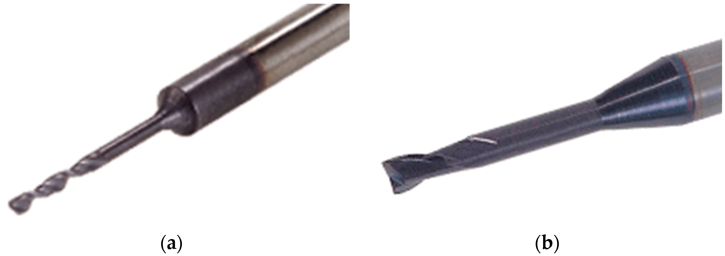
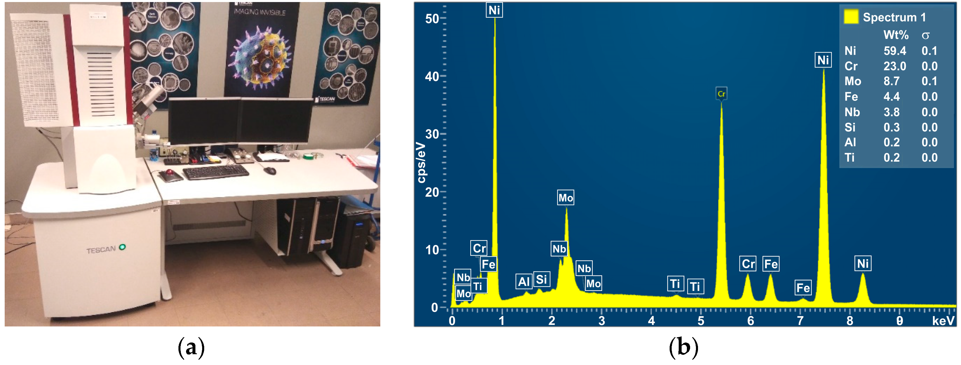
2.1. Material and Tool

In the tests, Inconel 625 alloy sheets with a thickness of 0.75 mm, a length of 30 mm, and a width of 20 mm were used as the test material. Inconel 625 (AMS55990) is a nickel-chromium-molybdenum alloy characterised by high corrosion resistance and high tensile strength over a wide temperature range. It is used in the production of components and equipment for use in extreme conditions such as high temperatures, pressures, and corrosion environments containing sulfuric acid, hydrogen fluoride, hydrochloric acid, and hydrogen fluoride. It is also used in the chemical, petrochemical, aerospace, and marine industries where corrosion resistance is required. Inconel 625 resists corrosion in both acidic and alkaline environments, including oxidative and reducing conditions. It also has high resistance to intergranular corrosion and fatigue cracking, making it an ideal material for use in equipment that is subject to corrosion and high temperatures.
Before starting the main tests, measurements of the selected mechanical and physical properties of the Inconel 625 alloy were carried out. The results of the mechanical and physical properties of the Inconel 625 alloy are presented in Table 1. The chemical composition of the Inconel 625 alloy (Table 2) was determined by X-ray diffraction (XRD) analysis on an Empyrean diffractometer (Malvern Panalytical Ltd., Malvern, UK).
Mechanical micro-drilling studies were performed using micro-drills with a titanium aluminum nitride (TiAlN) coating supplied by ISCAR Cutting Tools (Figure 1a). The base material of the tool was fine-grained tungsten carbide. The diameter of the drills used in all experiments was 0.8 mm and the point angle was 140°. Prior to the mechanical drilling process, the surface of the drilled hole was pre-milled with a 0.8 mm 2-flute end mill (Figure 1b) to provide a flat surface on the side where the drill enters the workpiece. For twist drills, the rotational speed of the tool was n = 2000 rpm and the feed rate was vf = 28 mm/min. The holes were drilled at an angle of 30° to the surface of the plates.
Figure 2 shows a hole drilled using a mechanical drilling process. Based on the observations, it was noticed that the edge of the hole at the exit of the drill from the workpiece material has long burrs (usually there is only one burr). Such a situation may cause chipping or breaking of the drill bit. Such burrs can catch on the drill during the retraction of the tool which may result in tool breakage. During the investigations, this situation occurred twice. Of course, this led to a broken drill bit.

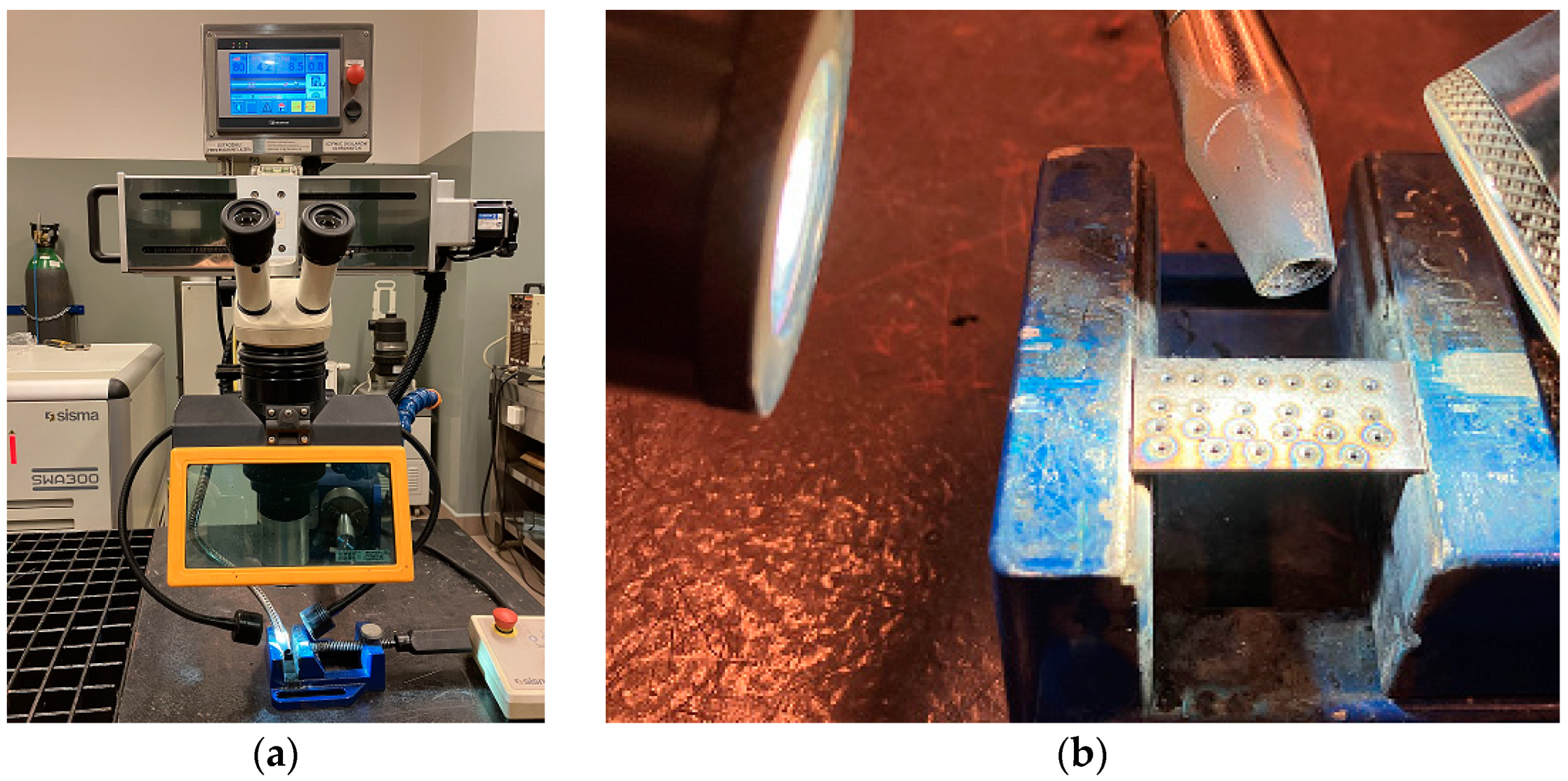
2.2. Experimental Setup
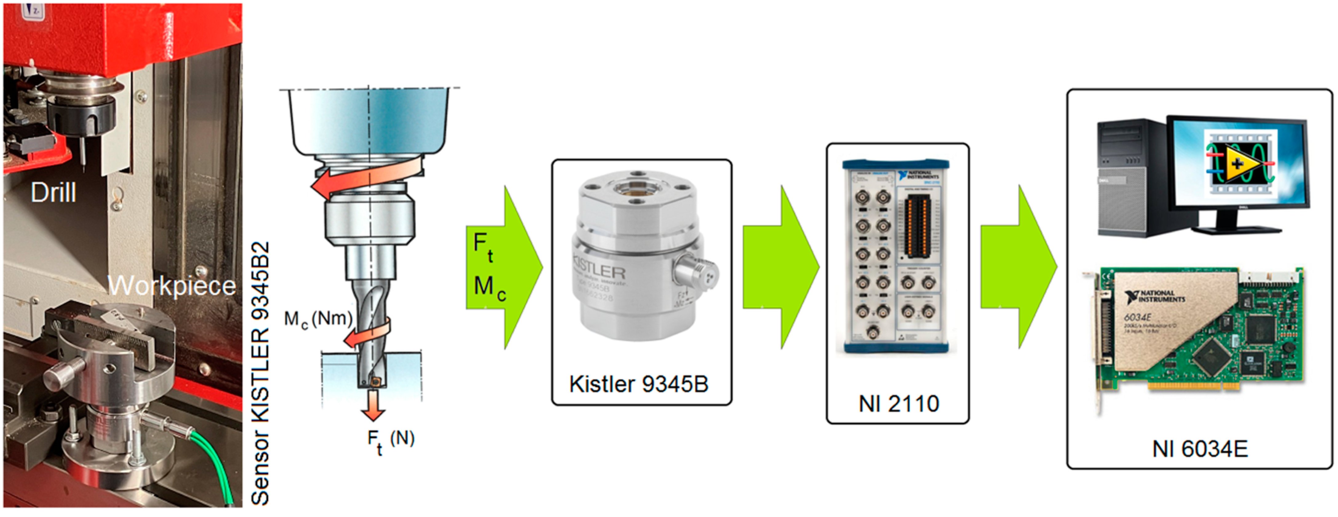
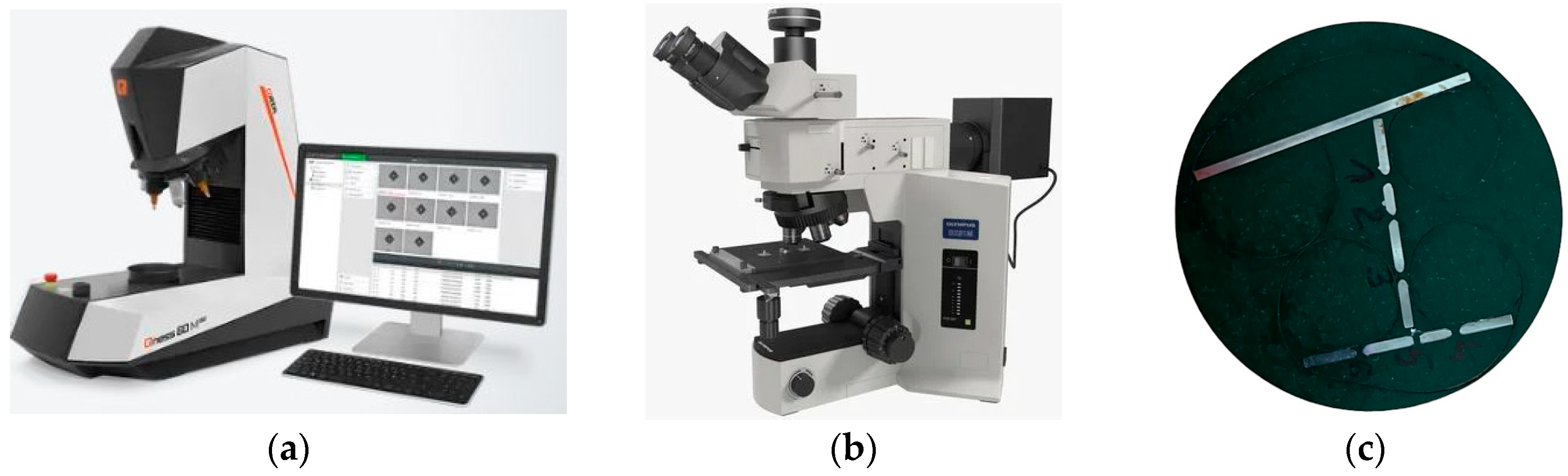
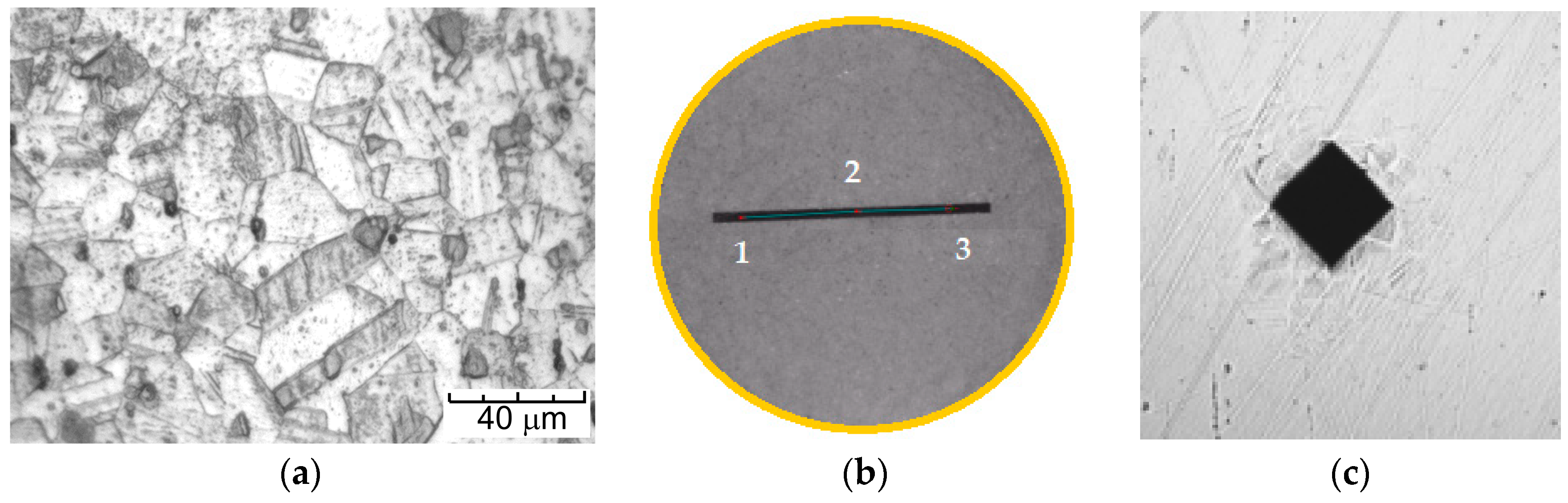
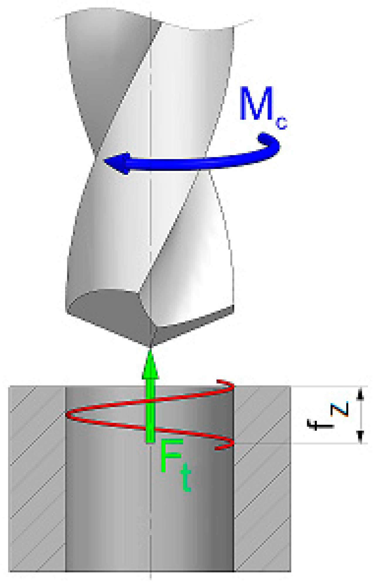
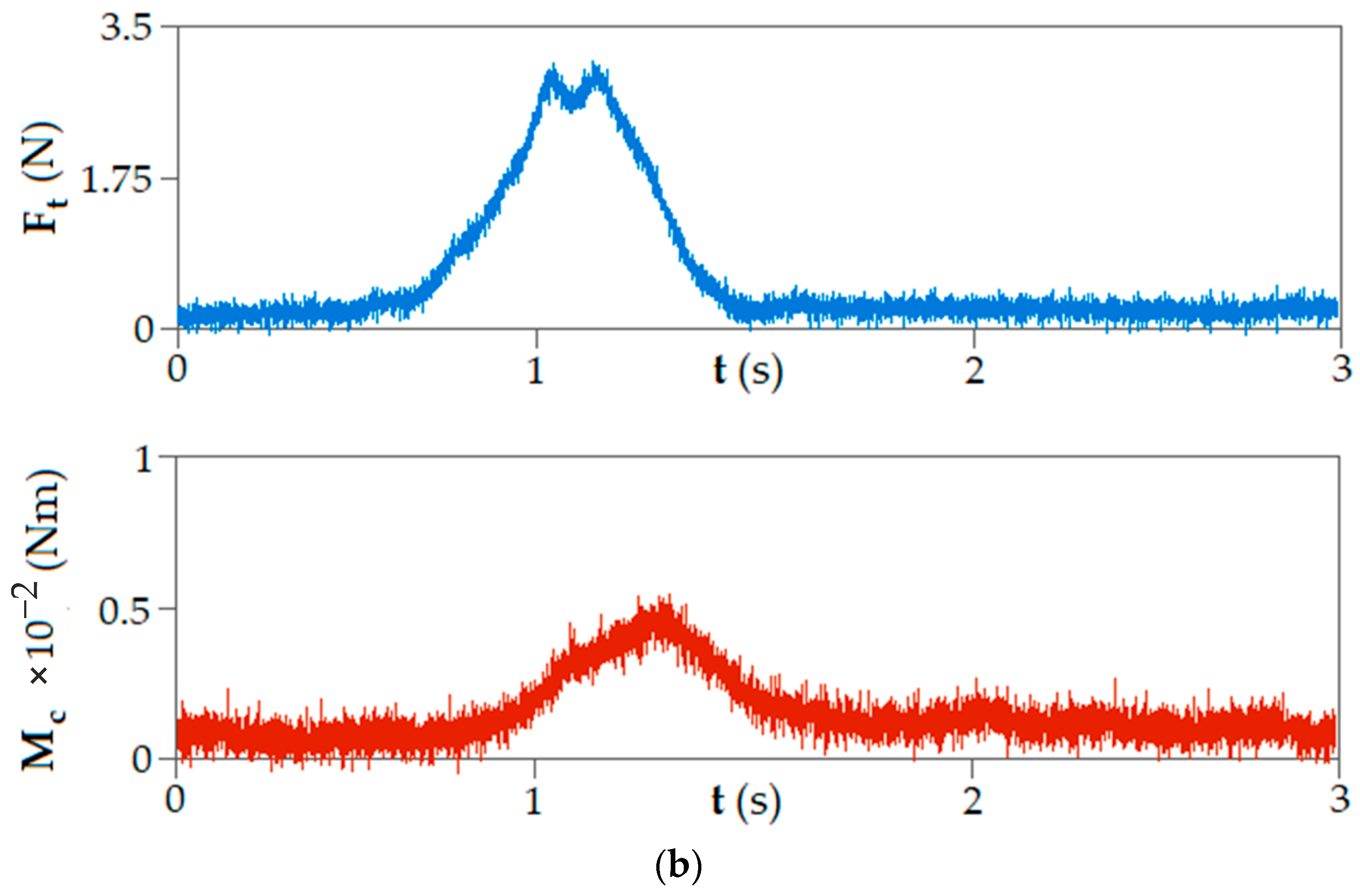
Laser drilling tests were carried out using a Sisma SWA 300 laser welding system (Figure 3a) (Sisma S.p.A., Vicenza, Italy) powered by a flash lamp-pumped Nd:YAG that generates a laser beam with a wavelength of 1064 nm. The technical specification of the SWA 300 laser welding system is presented in Table 3.
The focal point of the laser was 120 mm above the surface of the Inconel 625 alloy plate. The laser beam was focused into beam diameters of 600 and 800 μm on the surface of the workpiece. To laser drill inclined holes at 30° to the plate surface, the nozzle and axis of the laser beam were tilted (Figure 3b) while the workpiece remained horizontal. In accordance with the experience gained in previous studies by the authors, other parameters such as pulse duration and support gas (argon) pressure were kept constant at 1.5 ms and 4 bar, respectively. During the laser drilling process, two parameters were changed (pulse frequency and beam diameter). The full plan of the experiments is presented in Table 4. The aim of the laser drilling was to make holes with a diameter comparable to the length of the drill bit edge.
In the conducted micro-drilling tests, the drilling process was carried out in two ways. Sequential micro-drilling experiments were performed: a combination of laser drilling with subsequent mechanical drilling and only using a conventional mechanical drilling process. The purpose of this approach was to later compare the technological aspects of both processes.
The mechanical drilling process was carried out on an EMCO® CNC vertical milling machine (EMCO GmbH, Hallein, Austria). As part of the tests, holes were made both by the mechanical drilling process and re-drilling after the previously carried out laser drilling process. During the tests, the following signals were recorded: cutting torque (Mc) and axial force (Ft). The values of the axial force and cutting torque were measured using a Kistler 9345B2 (Kistler®, Winterthur, Switzerland) piezoelectric industrial sensor. Sensor signals were recorded on a personal computer (PC) disc via a 6034E 16-bit analogue/digital card (National Instruments Corporation®, Austin, TX, USA) at a sampling rate of 50 kHz. A schematic diagram of the configuration of the measurement track and the measurement data archiving system is shown in Figure 4.

2.3. Measurement

In addition, for cognitive purposes, a spectral analysis of the elements included in the material (Figure 5b) was performed using a TESCAN® MIRA3 (Brno, Czech Republic) scanning electron microscope (Figure 5a).
Both for the analysis of the chemical composition and for the microstructural analysis, the preparation of the samples for testing was identical. Initially, the Inconel 625 alloy samples were embedded in epoxy resin (Figure 6c). Then, the samples for metallographic testing were wet mechanically polished with 120–2500 grit paper. Finally, diamond paste (grain sizes 1 μm and 3 μm) was used to polish the surface of the samples. The surface was etched using a reagent with the following chemical composition: 10 mL H2SO4, 100 mL HCl, and 10 g CuSO4. The samples were etched at room temperature for about 15 s to allow for the subsequent observation of the microstructure. Metallographic observations of the samples were carried out using an Olympus BX51M optical microscope (Figure 6b) (Olympus, Tokyo, Japan) coupled to a computer with Olympus Stream Essentials software Version 2.4 with magnifications from ×50 to ×1000.
Hardness distribution measurements before and after the micro-drilling process on the samples were carried out using the Vickers method on a Qness 60M hardness tester (Figure 6a) (Qness, Mammelzen, Germany) in accordance with ISO 6507. A load of 9.807 N (HV 1) and a test time of 10 s were applied.
When observing the microstructure of the Inconel 625 alloy, before the micro-drilling process, the presence of a typical austenitic structure consisting of equiaxed grains with an average grain size of 76 μm was observed, and there were also twins, as shown in Figure 7a. The minimum measured hardness of the material was 212.13 HV1 and the maximum value was 233.06 HV1, while the hardness value at the measuring point no. 1 (Figure 7b) was 223.09 HV1. Figure 7c shows an example indentation. The results of the hardness measurements are shown in Figure 8.

3. Results and Discussion

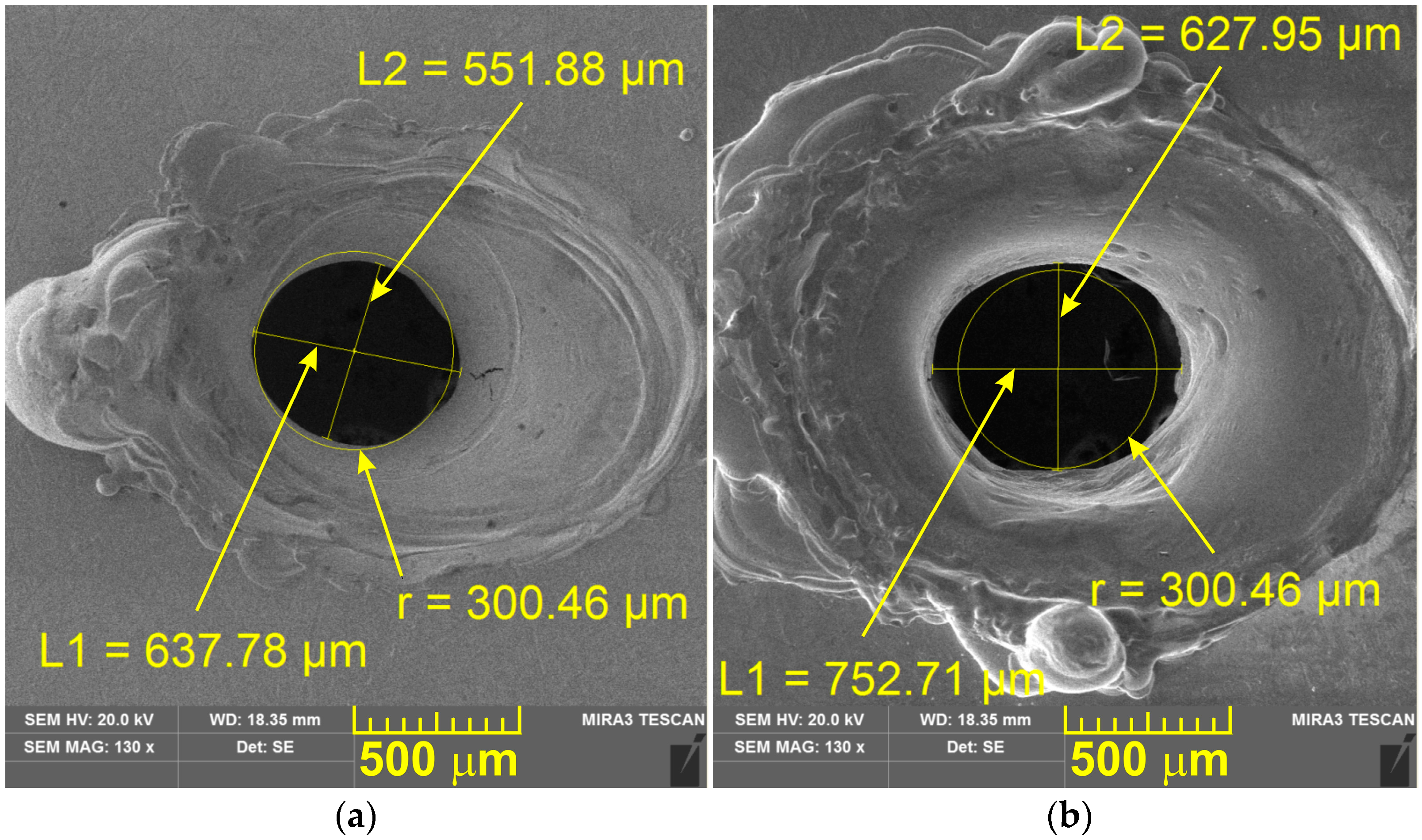
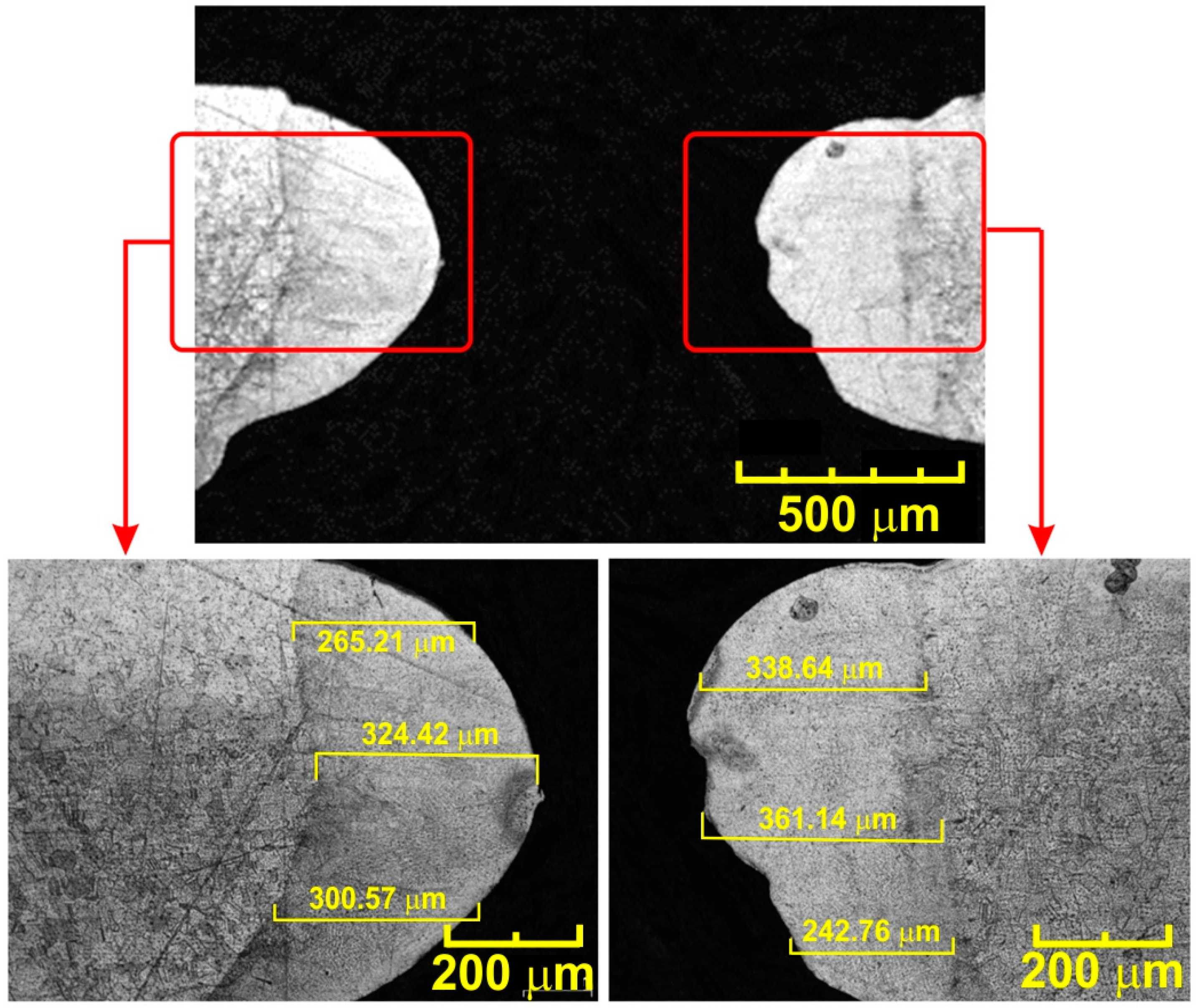
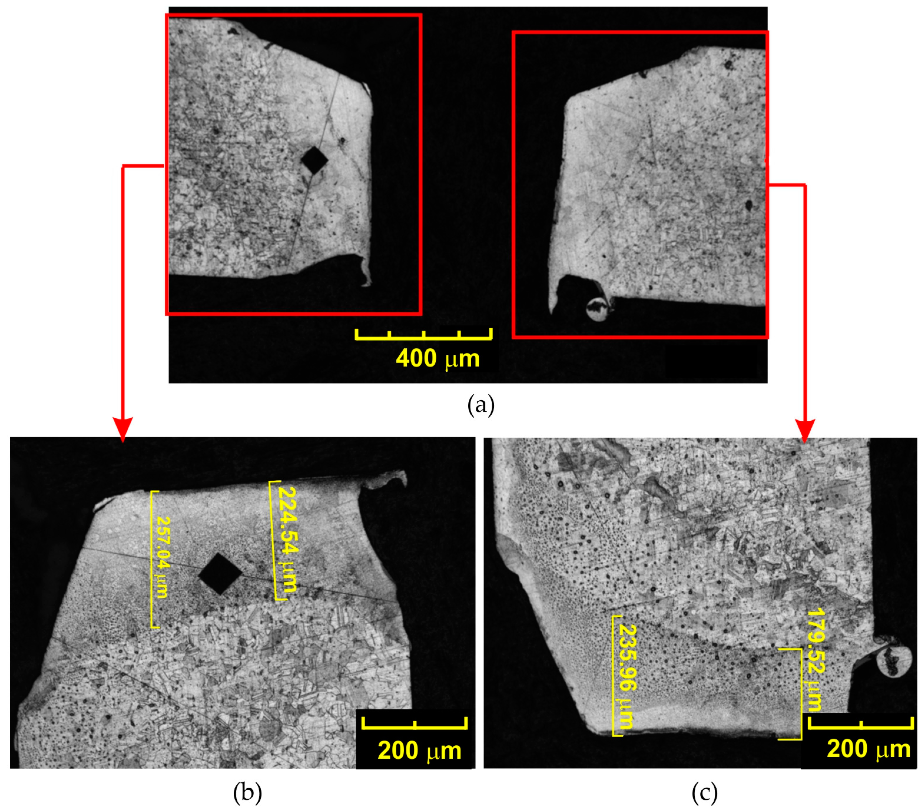
3.1. Shape and Structure of Holes Made with a Laser

Figure 9 shows sample micrographs of the holes obtained during drilling with the use of a laser. In all cases, it was observed that the diameter of the hole obtained is not uniform along the circumference, which adversely affects the roundness errors of the hole. The roundness deviation is the greatest distance between the real circle and the adjacent circle. The adjacent circle is the circle with the smallest diameter described on the outline of the hole. The centre of the laser-drilled hole should be symmetrical with the walls of the hole, as found by Okasha et al. [39]. Such a situation will be possible if the roundness errors of the obtained holes are as small as possible. This is because in order to stabilise the drill during subsequent mechanical re-drilling, it is necessary to balance the cutting forces at the two opposite cutting edges of the drill. According to Okasha et al. [39], the micro-drill’s instability at the entry side is due to the unbalanced force exerted on the tool lips. During the drilling of angled holes, the drill tip is subjected to a high lateral force which causes the micro-drill to bend and eventually break the tool [44]. Okasha et al. [41] suggested that the diameter of the laser pre-drilled hole should be smaller than the length of the chisel edge in order to reduce drill wander.
Drilling so-called hollow profiles, which can include fuel injector nozzles, without damaging the opposite wall, is one of the greatest challenges during the laser micro-drilling process. For hollow parts, after the laser beam penetrates the front wall, it can then damage the opposite wall. Filling the resulting wall defect with a blocker is a common method of alleviating damage to the back walls [45]. As part of the experimental research, it was assumed that it was not possible to make holes on the other side of the material. This is a common situation that occurs when drilling holes in hollow profiles and blind holes.
It is clear from Figure 9 that the best acceptable roundness errors are for the T1 test. The diameters of the laser-drilled hole with an energy of 6.3 J in two perpendicular directions (Figure 9a) were L2 = 551.88 and L1 = 637.78 μm. However, when using the parameters from the T2 test, the diameters of the hole drilled by the laser with an energy of 11.4 J were L2 = 627.95 and L1 = 752.71 μm (Figure 9b). The entry diameter of the laser-drilled holes in the T1 test was less than 25% of the size of the 800 μm drill. For laser-drilled holes under the T2 test parameters, the resulting diameter was within ±13% of the diameter of the 800 μm drill. The smallest values of roundness errors were obtained for the T1 test parameters. The maximum roundness error for this test was 86 μm. For the T2 test, the maximum roundness error was 135 μm. Roundness errors in laser-drilled holes are a complex function of the process parameters. As found by Ng et al. [46], the best circularity is obtained by increasing the laser power and reducing the pulse width, which affects the diameter of the hole. The entrance hole diameter and hole taper decrease when the laser power decreases and the laser pulse frequency increases [47]. The degree of the taper, which is caused by the removal of molten and vaporised material from the hole, decreases with shorter pulse widths [48]. Figure 10 shows sample photographs of the microstructure of the material near the surface of holes obtained during laser drilling.
The average depth of the heat-affected layer for the T2 test was 284 µm. For the T1, test it was 94 µm. To ensure that mechanical drilling minimises the effects of imperfections associated with laser-drilled holes (i.e., HAZ), the diameter of the drill bit must be slightly larger than the diameter at which imperfections occur in the laser drilling process. The correct final diameter obtained after the mechanical drilling process should be greater than the sum of the laser hole diameter plus twice the depth of the heat-affected layer. For the T2 test presented, the diameter of the hole and the depth of the heat-affected layer are 551 and 338 μm, respectively. Therefore, the minimum required drill diameter should be at least 1200 μm. Figure 11 shows micrographs of the material microstructure at the edge of the hole obtained after the final mechanical drilling process using a drill bit with a diameter of 800 μm. As can be seen, the use of a drill with a diameter smaller than the recommended one in the mechanical drilling process, due to the abovementioned problems, does not completely eliminate the HAZ created in the laser drilling process. The HAZ with a depth of approximately 250 μm is clearly visible here. Laser drilling typically produces a large HAZ and a recast layer, as observed by Dausinger [49]. Mechanical drilling eliminates the laser drilling defects at the hole entrance [39].
During the planned subsequent mechanical drilling, care was taken to ensure that the axes of the laser-cut holes could be precisely located. For this purpose, the Inconel 625 alloy plate was mounted in a special holder with the possibility of using positioning with a micrometrer screw to position it. Two holes with a diameter of 500 μm were drilled in it on the perpendicular sides of the plate. Then, the holder with the plate was mounted in the working zone of the CNC machine. The holes located in this plate served as reference points for the CNC machine. The maximum eccentricity created between the hole made by the laser and the hole made by the drill was 15 μm.

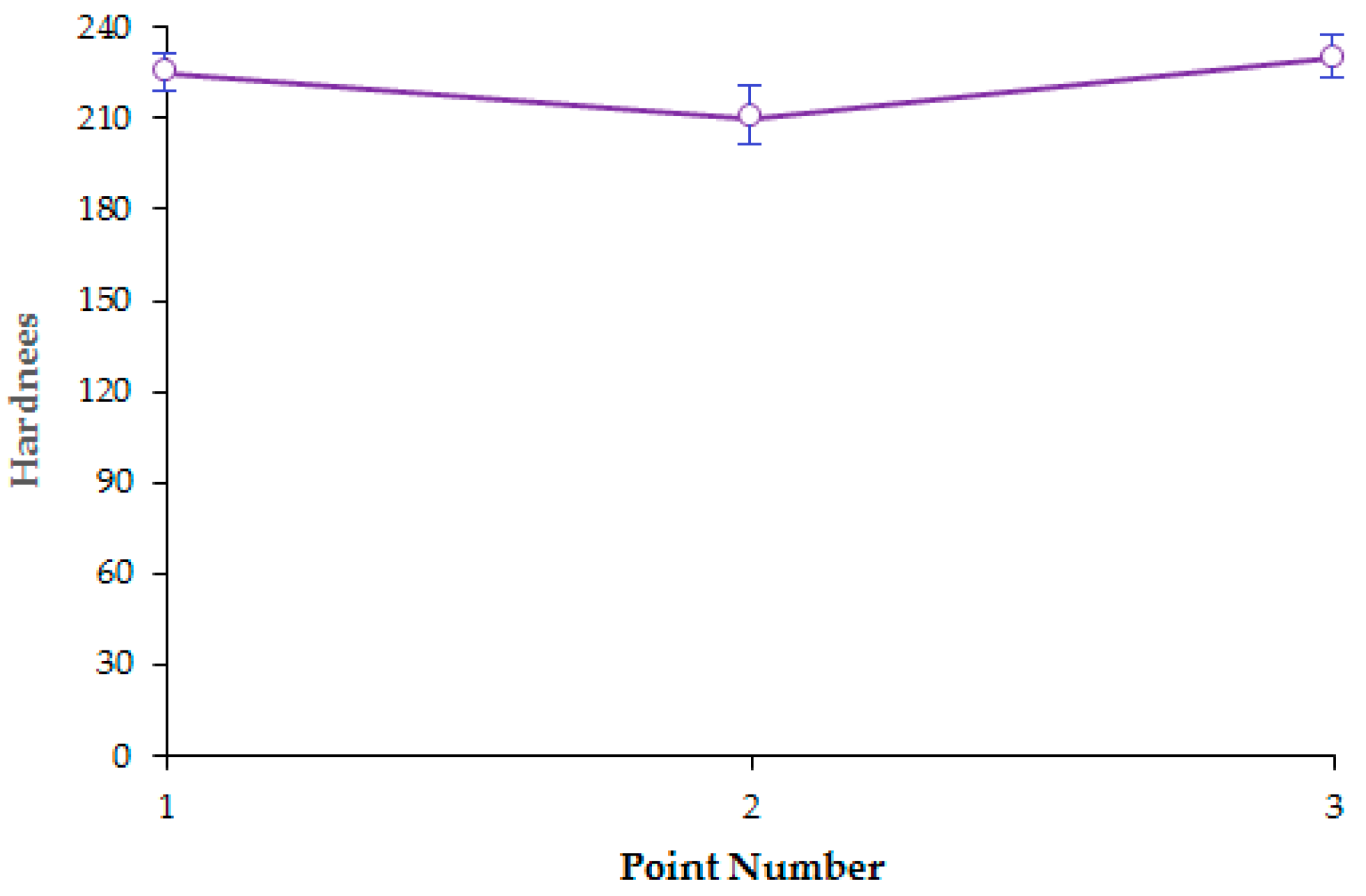
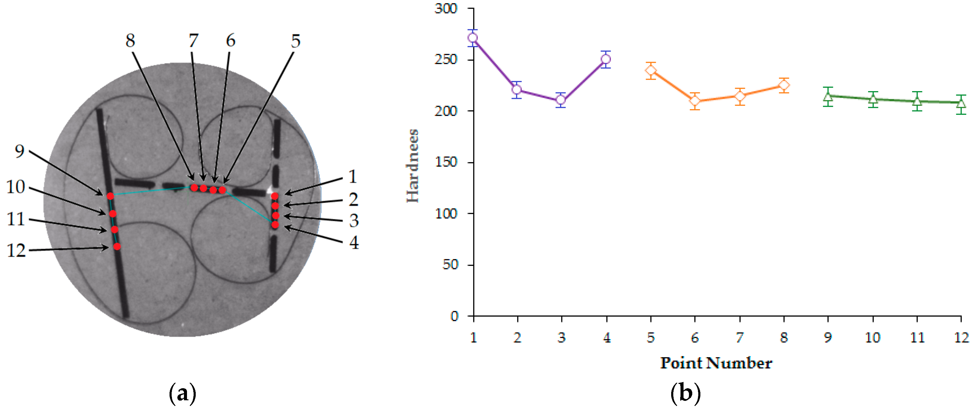
3.2. Hardness of the Surfaces of Holes Made with a Laser

The results of the hardness test for the samples from the T1 and T2 tests carried out using the Vickers method are shown in Figure 12. The hardness of the Inconel 625 alloy after the T2 test was measured at points 1, 2, 3, and 4. At these points, the hardness was 261 HV1, 221 HV1, 211 HV1, and 248 HV1 respectively. Hardness measurement points 1 and 4 were located in the HAZ. Whereas, points 2 and 4 were located in the base metal, not subjected to the influence of the laser beam. The hardness of the Inconel 625 after the T1 test was measured at points 5, 6, 7, and 8, and the following results were obtained: 239 HV1, 212 HV1, 210 HV1, and 227 HV1, respectively. Hardness measurement points 5 and 8 were located in the HAZ. Points 6 and 7 were located in the base material. The remaining measurements at points 9, 10, 11, and 12 concerned a section of the Inconel 625 alloy plate not subjected to the laser drilling process. At these points, the following hardness values were obtained: 212 HV1, 211 HV1, 210 HV1, and 210 HV1, respectively. The change in the laser drilling parameters resulted in an increase in the average hardness from 8% (T1 test) to 30% (T2 test) in the heat-affected layer compared to the hardness value of the base Inconel 625 alloy (approx. 210 HV1). This increase is caused by the fact that, with the increase in thermal energy supplied to the material, the temperature gradient increases, which in turn contributes to the formation of carbide fractions with different matrices and changes in the microstructure of the material.
The microstructure of the Inconel 625 alloy in the heat-affected layer is shown in Figure 13. The microstructure consists of austenite dendrites (the presence of which was confirmed by XRD analysis) and secondary carbide phases. According to the EDS analysis, the austenite dendrites mainly consist of nickel, chromium, and iron, while the secondary phases are characterised by high concentrations of carbon, niobium, molybdenum, and titanium. In the case of the Inconel 625 alloy, the columnar growth of the dendrites was caused by the temperature gradient during solidification, with the dendrites growing in the opposite direction to the heat transfer.

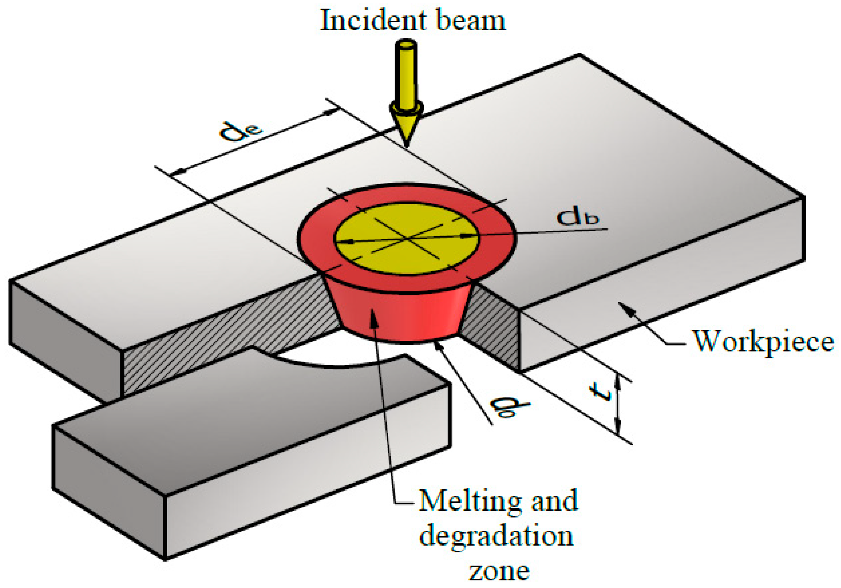
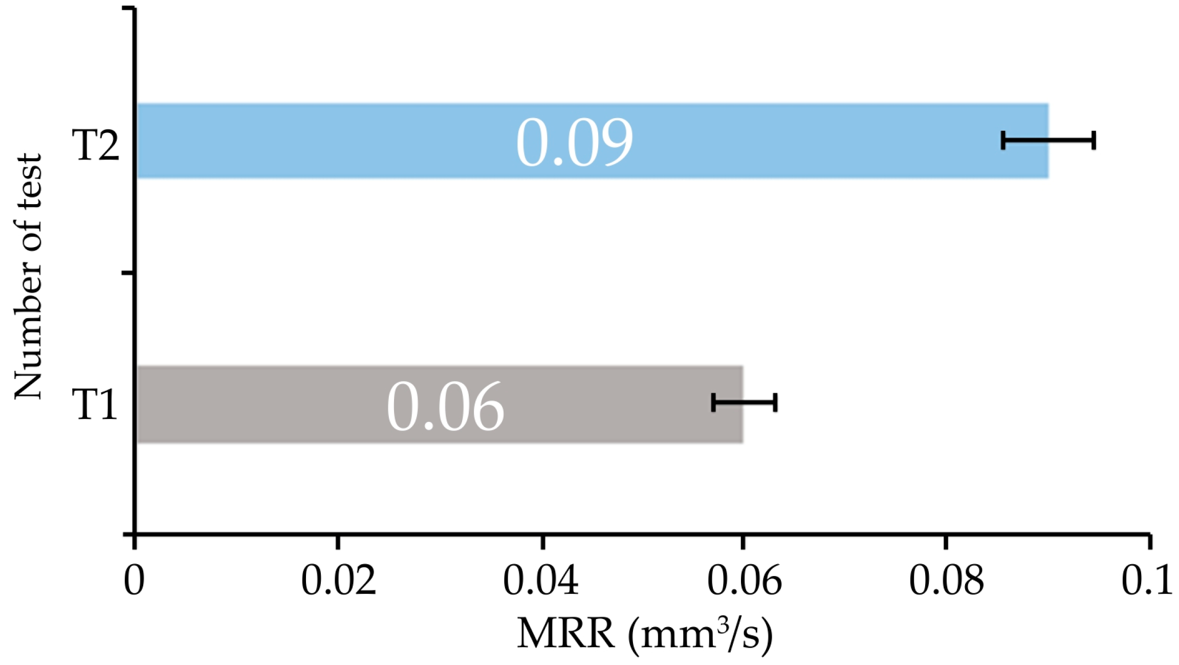
3.3. Material Removal Rate and Volumetric Efficiency in Laser Drilling

The material removal rate (MRR) in a drilling process is the volume of material removed from the cutting gap in the same time it takes for the laser beam to travel a distance equal to the thickness of the material. Several well-known parameters influence the rate of material removal in laser drilling, including laser power, pulse time, and laser beam diameter. In conventional laser cutting, the volume of material removed can be calculated by measuring the width of the top and bottom kerf. According to the kerf width measurements, the cross-section of the kerf cut may be similar to a trapezoid, wider on the top surface of the plate with a smaller width on the bottom surface, as shown in Figure 14.
The volume of material removal in laser drilling can be roughly expressed as the volume of a cone ring (coloured red in Figure 14). The relationship allowing calculation of the material removal volume (MRV) can therefore be expressed as:
MR v = π 3 d e 2 2 + d e 2 × d o 2 + d b 2 2 × t
where de and do are diameters of the upper and lower hole, respectively, t is the sheet thickness, and db is the diameter of the focused laser beam. The MRR can be calculated as follows:
MRR = MR v T c
where Tc is the interaction time of the laser on the material. The interaction time is the time in which the focused laser beam travels a distance equal to the thickness of the material t. Using the relationship expressed in Equation (2), we can determine the MRR for the T1 and T2 tests. Figure 15 shows the MRRs for the two tests performed. For comparison, the value of the MRR for the mechanical drilling process with a drill with a diameter of 0.8 mm in solid material (without pre holes) and with the cutting parameters adopted in the tests is 0.8 mm3/s.

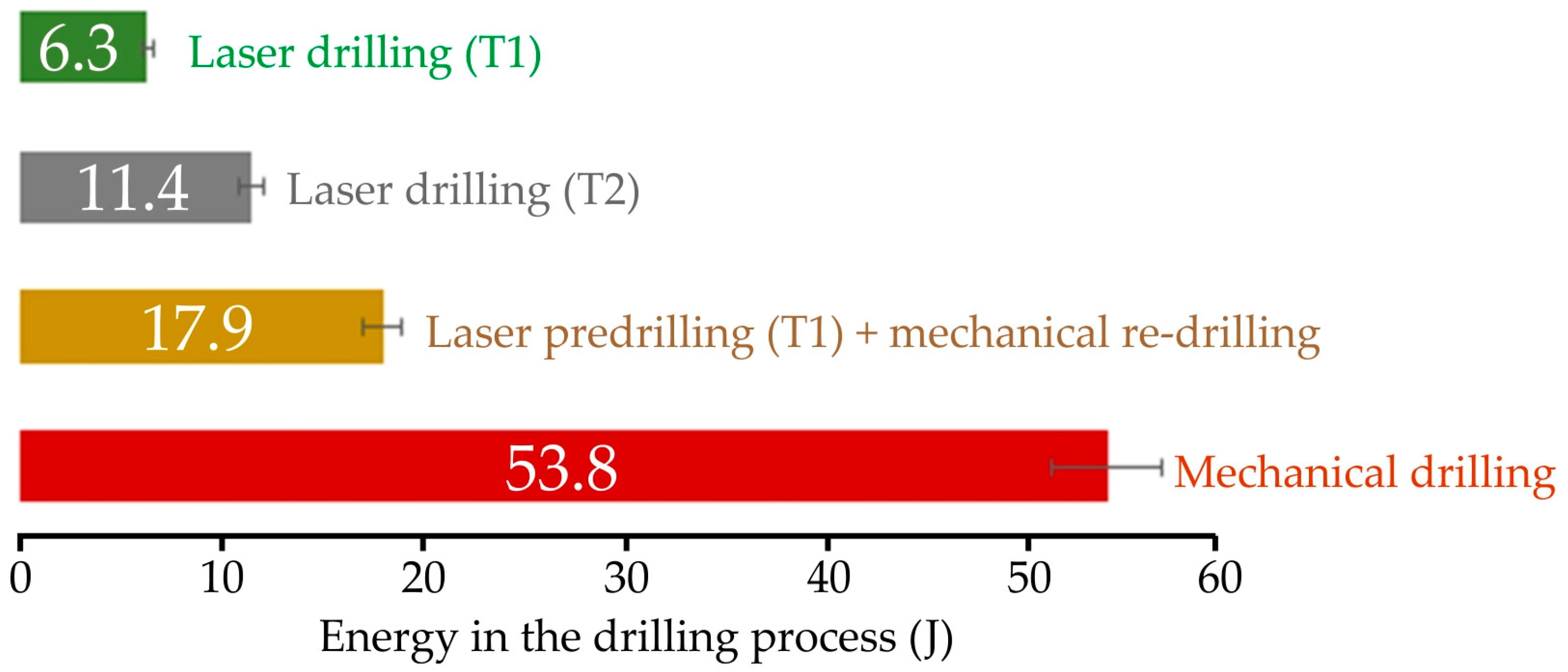
3.4. Energy in the Mechanical Drilling Process
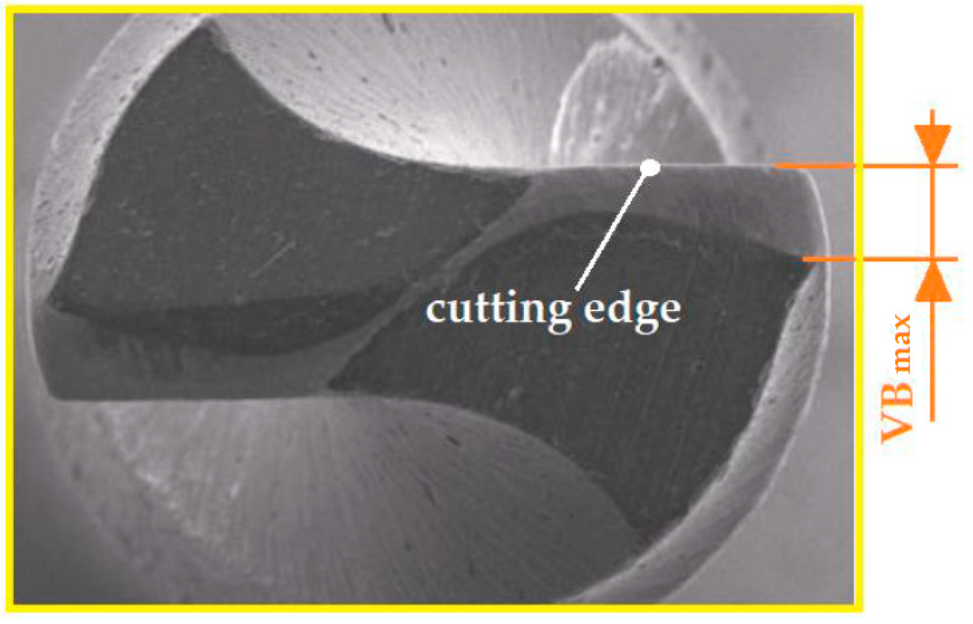
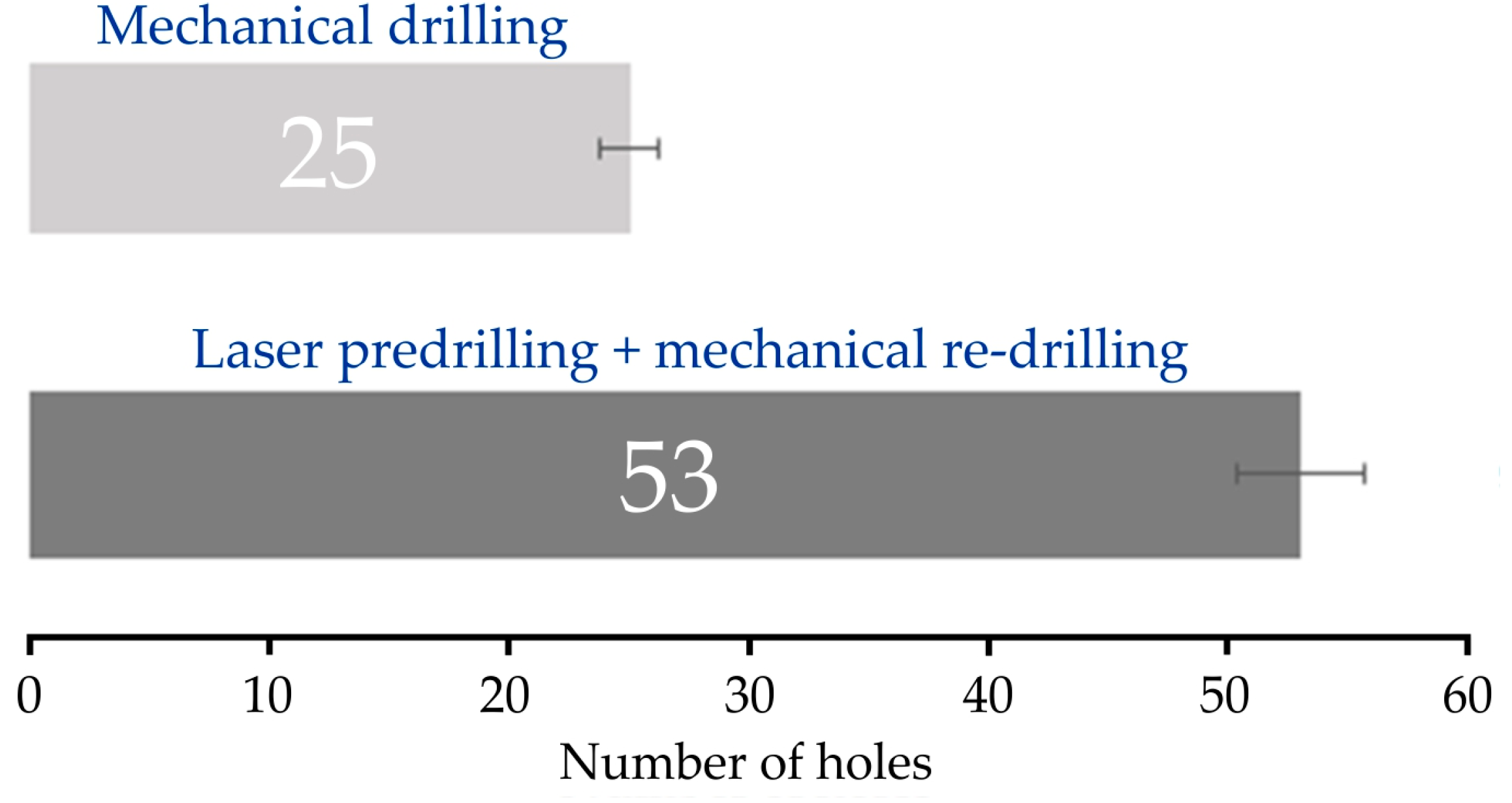
Figure 16 shows the load in the form of the axial for 3ce (Ft) and cutting torque (Mc) that affect the drill bit during the drilling process.
Let the drill make an elementary rotation through an angle δφ. This will cause a virtual axial shift of the drill by δz at the same time. Taking into account that the drill is subjected to a cutting torque of Mc, we can find that the virtual work from that moment is Mc·δφ. The virtual work from the force Ft is negative and equals –Ft·δz. The equation resulting from the principle of virtual work describing the energy E will therefore take the form:
M c δ φ F t δ z = E
It is easy to determine the relationship between δφ and δz. With one full revolution of the drill (with a rotation of an angle equal to 2π), the drill undergoes a virtual displacement in the axial direction equal to the value of the drill’s feed per revolution fz. Therefore, we can set up the following proportion:
δ z δ φ = f z 2 π
Hence, we find:
δ z 2 π f z = δ φ
After substituting Equation (5) into Equation (3), we obtain:
M c 2 π f z F t δ z = E
It can be assumed that sequential laser and mechanical drilling should be accompanied by a gradual change in the axial force Ft and cutting torque Mc, which should additionally reduce the energy value and increase the durability of the cutting tool. Figure 17 presents exemplary courses of the recorded axial force and cutting torque for a selected sample from the T1 test. Figure 17a shows the course recorded during the mechanical drilling process in solid material with the adopted cutting parameters. Figure 17b, on the other hand, shows the signals recorded in the re-drilling process.
As can be seen in Figure 17, both the value of the axial force Ft and the cutting torque Mc significantly differ in value, depending on whether the drilling or re-drilling process is performed. For drilling, the average value of the force is about 50 N and the average value of the cutting torque is 1.5 Nm. On the other hand, in the re-drilling process, the average force value is about 3 N, and the average cutting torque value is 0.5 Nm. Thus, it can be concluded that the value of the axial force occurring in the re-drilling process in the analysed case is about 6% of the value of the force occurring in the drilling process. This situation can be explained by the fact that, in the drilling process, the chisel edge of the drill is responsible for the value of the axial force. The major part of the axial force value comes from the influence of the chisel edge of the drill on the workpiece. A decrease in the cutting forces in sequential drilling was also observed by Okasha et al. [39].
For re-drilling, the share of the chisel edge of the drill in the drilling process is negligible. The laser-predrilled hole helps to reduce the squeeze action in front of the chisel edge [39]. However, in the case of the cutting torque, there is not such a large decrease in value (about 65%). This is due to the change (decrease) in the cross-section of the cut layer. Knowing the values of the axial force and the cutting moment, we can use Equation (6) to determine the energy demand in both the drilling and re-drilling processes. Figure 18 presents the energy demand depending on the process being implemented.
As can be seen in Figure 18, the highest energy requirement is for drilling, which is approximately 54 J. The lowest recorded energy requirement is for laser drilling in the T1 test sample, approximately 6 J. For laser (T1 test) and mechanical re-drilling, the energy requirement is approximately 18 J.
In summary, it can be seen that the proposed sequential laser drilling and mechanical re-drilling process allows for a reduction in energy demand of up to 60% compared to mechanical drilling. Okasha et al. [39] found that the reduction of mechanical energy in the mechanical processing of a laser-predrilled hole was associated with a comparable reduction in heat release. Much of this heat generated in mechanical micro-drilling is conducted into the workpiece and tool; however, a portion remains in the chip [50]. A high temperature in the contact zone adversely affects thermally activated wear mechanisms, resulting in reduced tool life [51]. Thus, from the point of view of drill life, prior laser pre-drilling is advantageous. Hot chips are another source of heat affecting tool life and thermal stresses in the drill [52].

3.5. Tool Wear

In the aerospace industry, difficult-to-cut materials such as stainless steel, titanium, or Inconel alloys are often used. The machining of these materials is a relatively difficult topic, and therefore, there is a lack of experience regarding the most efficient, economical cutting conditions for these materials. Various attempts have been made to improve the cutting performance of these materials while keeping the tool life within reasonable limits. For many years, the processing of heat-resistant, difficult-to-cut materials has been a serious problem and, at the same time, has been the subject of research by many research centres. Nickel-based superalloys are widely used in the aerospace industry due to their exceptional thermal resistance and ability to maintain their mechanical properties at temperatures as high as 700 °C. However, these materials are difficult to machine due to their shear strength, hardening tendency, highly abrasive carbide particles in the microstructure, and low thermal conductivity. While, in the case of Inconel 718, there is a relatively large number of publications that have presented the results of research in the field of processing optimisation, the number of publications on the machining of Inconel 625 is negligible and superficial. On the other hand, new rapidly developing tool materials offer the opportunity to significantly increase machining efficiency. Choosing between the offers of different manufacturers requires appropriate comparative tests, which are costly and time-consuming.
After the initial determination of the cutting parameters for a given tool, based on the manufacturer’s recommendations, a single operation was performed consisting of drilling a hole. If the procedure was uneventful (e.g., there was no catastrophic blunting of the blade), after the drilling, a decision was made about the ability of the given blade to continue working; that is, to perform another treatment. The wear of the flank face VBmax (Figure 19) was used to assess the wear of the cutting edge. Moreover, indirect indicators of blade wear were also observed. As indirect criteria for the blunting of the cutting edge, the formation of flashes and burrs on the edge of the hole was assumed. An entrance burr is formed on the entrance surface as the workpiece material undergoes plastic flow [53]. The exit burr is larger than the entrance burr and is a result of pushing the ragged material off the surface of the drilled material. Most previous studies [54,55,56] have focused on burr formation in the micro-drilling of holes with a diameter of less than 1 mm. According to Okasha et al. [39], sequential drilling reduces the burr size by 75%.
Sequential laser drilling followed by mechanical re-drilling increases the tool life by approximately two times (Figure 20) compared to mechanical drilling within the range of the cutting parameters tested. Okasha et al. [39] found that when using sequential laser and mechanical drilling to produce 500 mm-diameter micro-holes in an Inconel 718 alloy, there was a 240% increase in tool life compared with purely mechanical micro-drilling. This can be attributed to the fact that, at the feed rate used in the tests, the high mechanical and thermal loads exerted on the drill reduce the tool life. Thanks to the laser pre-drilled hole, we thus contribute to reducing the axial forces of the mechanical re-drilling. Therefore, the increase in the tool life in sequential drilling is more significant at higher feed rates. Sequential drilling is a promising method for increasing tool life when micro-drilling Ni-based alloys [39]. According to Rahman et al. [44], sequential laser and mechanical drilling can solve the problems of recast layer formation, poor geometry, and back-wall damage associated with laser drilling.

4. Conclusions

The paper presents the results obtained from the sequential laser and mechanical micro-drilling process of Inconel 625 alloy plates at an angle of 30°. The use of laser pre-drilling reduces the cross-section of the cut layer compared to mechanical drilling of the solid material. However, the use of preliminary laser drilling causes discrepancies in terms of shape and dimensions, as well as in the microstructure of the workpiece material. Below are the important conclusions obtained from the conducted research:
Laser drilling resulted in an increase in the average hardness from 8% (T1 test) to 30% (T2 test) in the HAZ compared to the hardness value of the as-received Inconel 625 alloy. During laser micro-drilling with (1) a pulse frequency of 20 Hz and beam diameter of 0.6 mm and (2) a pulse frequency of 10 Hz and beam diameter of 0.8 mm, the depths of the HAZ were 284 mm and 94 mm, respectively. Sequential laser and mechanical drilling are accompanied by a gradual change in the cutting torque and axial force. In the re-drilling process, the average force value is about 3 N, and the average cutting torque value is 0.5 Nm. In the case of drilling, the average value of the force is about 50 N and the average value of the cutting torque is 1.5 Nm. The reduction in the axial force in the re-drilling process by about 94% compared to the drilling process is due to the fact that the share of the chisel edge of the drill in the drilling process is negligible. However, for the cutting torque, this value in re-drilling is reduced by about 65% compared to the drilling process. Based on the wear of the flank face, sequential laser drilling followed by mechanical re-drilling increases the tool life by about 100% compared to the mechanical drilling process. At the same time, the energy demand of laser pre-drilling followed by mechanical re-drilling is equal to about 35% of the energy demand in mechanical drilling.

Author Contributions

Conceptualization, K.S. and J.Z.-S.; methodology, K.S., J.Z.-S. and T.T.; validation, K.S., J.Z.-S., K.Ż. and T.T.; formal analysis, K.S., J.Z.-S., K.Ż. and T.T.; investigation, K.S. and J.Z.-S.; data curation, K.S., J.Z.-S., K.Ż. and T.T.; writing—original draft preparation, K.S., J.Z.-S. and T.T.; writing—review and editing, K.S., K.Ż. and T.T. All authors have read and agreed to the published version of the manuscript.

Funding

This research received no external funding.

Institutional Review Board Statement

Not applicable.

Informed Consent Statement

Not applicable.

Data Availability Statement

The data presented in this study are available on request from the corresponding author.

Conflicts of Interest

The authors declare no conflict of interest.

References

  1. D’Addona, D.M.; Raykar, S.J.; Narke, M.M. High Speed Machining of Inconel 718: Tool Wear and Surface Roughness Analysis. Procedia CIRP 2017, 62, 269–274. [Google Scholar] [CrossRef]
  2. Ezugwu, E.O.; Wang, Z.M.; Machado, A.R. The machinability of nickel-based alloys: A review. J. Mater. Process. Technol. 1999, 86, 1–16. [Google Scholar] [CrossRef]
  3. Rathi, N.; Kumar, P.; Khatkar, S.K.; Gupta, A. Non-conventional machining of nickel based superalloys: A review. Mater. Today Proc. 2023; in press. [Google Scholar] [CrossRef]
  4. Selbmann, E.; Preiẞ, M.; Achour, A.B.; Teicher, U.; Hänel, A.; Ihlenfeldt, S. Investigation of bio-based cooling lubricants for the machining of aircraft stainless steels. Procedia CIRP 2022, 110, 47–52. [Google Scholar] [CrossRef]
  5. Singh, A.; Ghosh, S.; Aravindan, S. State of art for sustainable machining of nickel-based alloys using coated and uncoated tools and machining of high strength materials using surface modified cutting tools. Tribol. Int. 2022, 170, 107517. [Google Scholar] [CrossRef]
  6. Salvi, H.; Vesuwala, H.; Raval, P.; Badheka, V.; Khanna, N. Sustainability analysis of additive + subtractive manufacturing processes for Inconel 625. Sustain. Mater. Technol. 2023, 35, e00580. [Google Scholar] [CrossRef]
  7. De Bartolomeis, A.; Newman, S.T.; Shokrani, A. High-speed milling Inconel 718 using Electrostatic Minimum Quantity Lubrication (EMQL). Procedia CIRP 2021, 101, 354–357. [Google Scholar] [CrossRef]
  8. Dureja, J.S.; Singh, R.; Singh, T.; Singh, P.; Dogra, M.; Bhatti, M.S. Performance evaluation of coated tool in machining of stainless steel (AISI 202) under minimum quantity lubrication (MQL). Int. J. Precis. Eng. Manuf.-Green Technol. 2015, 2, 123–129. [Google Scholar] [CrossRef]
  9. Jovicic, G.; Milosevic, A.; Kanovic, Z.; Sokac, M.; Simunovic, G.; Savkovic, B.; Vukelic, D. Optimization of Dry Turning of Inconel 601 Alloy Based on Surface Roughness, Tool Wear, and Material Removal Rate. Metals 2023, 13, 1068. [Google Scholar] [CrossRef]
  10. Lai, Z.; Wang, C.; Zheng, L.; Huang, W.; Yang, J.; Guo, G.; Xiong, W. Adaptability of AlTiN-based coated tools with green cutting technologies in sustainable machining of 316 L stainless steel. Tribol. Int. 2020, 148, 106300. [Google Scholar] [CrossRef]
  11. Eltaggaz, A.; Zawada, P.; Hegab, H.; Deaib, I.; Kishawy, H. Coolant strategy influence on tool life and surface roughness when machining ADI. Int. J. Adv. Manuf. Technol. 2018, 94, 3875–3887. [Google Scholar] [CrossRef]
  12. Barbucha, R. Mikroobróbka laserowa metali. STAL Met. Nowe Technol. 2020, 3–4, 69–71. [Google Scholar]
  13. Muzykiewicz, W.; Łach, A. Analiza możliwości wykonania gęstych perforacji blach niekonwencjonalnymi technikami wysokoenergetycznymi. Obróbka Plast. Met. 2007, 18, 13–21. [Google Scholar]
  14. Pattanayak, S.; Panda, S. Laser Beam Micro Drilling—A Review. Lasers Manuf. Mater. Process. 2018, 5, 366–394. [Google Scholar] [CrossRef]
  15. Raj, D.; Reddy, B.V.R.; Maity, S.R.; Pandey, K.M. Laser Beam Micromachining of Metals: A Review. Mater. Today Proc. 2019, 18, 98–103. [Google Scholar] [CrossRef]
  16. Ay, M.; Çaydaş, U.; Hasçalık, A. Optimization of micro-EDM drilling of Inconel 718 super alloy. Int. J. Adv. Manuf. Technol. 2013, 66, 1015–1023. [Google Scholar] [CrossRef]
  17. Chen, Y.C.; Liao, Y.S. Study on wear mechanisms in drilling of Inconel 718 superalloy. J. Mater. Process. Technol. 2003, 140, 269–273. [Google Scholar] [CrossRef]
  18. Venkatesan, T.; Jerald, J.; Pillingrin, J.C.; Asokan, P. Experimental investigation on micro drilling of Inconel 718 super alloy. Int. J. Mach. Mach. Mater. 2018, 20, 48–63. [Google Scholar] [CrossRef]
  19. Kivak, T.; Habali, K.; Şeker, U. The effect of cutting parameters on the hole quality and tool wear during the drilling of Inconel 718. Gazi Univ. J. Sci. 2012, 25, 533–540. [Google Scholar]
  20. Imran, M.; Mativenga, P.T.; Kannan, S. Evaluation of the effects of tool geometry on tool wear and surface integrity in the micro drilling process for Inconel 718 alloy. Int. J. Mach. Mach. Mater. 2012, 11, 244–262. [Google Scholar] [CrossRef]
  21. Imran, M.; Mativenga, P.T.; Gholinia, A.; Withers, P.J. Evaluation of surface integrity in micro drilling process for nickel-based super alloy. Int. J. Adv. Manuf. Technol. 2011, 55, 465–476. [Google Scholar] [CrossRef]
  22. Sager, A.M.M. Experimental Investigation of Machining of Nickel Based Superalloy Inconel 625. Master’s Thesis, Karabuk University, Karabuk, Turkey, 2018. [Google Scholar]
  23. Attanasio, A. Micro drilling of hard-to-cut materials: An experimental analysis. Int. J. Mechatron. Manuf. Syst. 2017, 10, 299–320. [Google Scholar] [CrossRef]
  24. Li, L.; Diver, C.; Atkinson, J.; Giedl-Wagner, R.; Helml, H.J. Sequential laser and EDM micro-drilling for next generation fuel injection nozzle manufacture. CIRP Ann. Manuf. Technol. 2006, 55, 179–182. [Google Scholar] [CrossRef]
  25. Brown, R.T. Hybrid laser process for shaped turbine-airfoil cooling holes. Proc. ICALEO 2000, 73, 205–212. [Google Scholar]
  26. Khanafer, K.; Eltaggaz, A.; Deiab, L.; Agarwal, H.; Abdul-Latif, A. Toward sustainable micro-drilling of Inconel 718 superalloy using MQL-Nanofluid. Int. J. Adv. Manuf. Technol. 2020, 107, 3459–3469. [Google Scholar] [CrossRef]
  27. Ceritbinmez, F.; Günen, A.; Gürol, U.; Çam, G. A comparative study on drillability of Inconel 625 alloy fabricated by wire arc additive manufacturing. J. Manuf. Process. 2023, 89, 150–169. [Google Scholar] [CrossRef]
  28. Agrawal, V.; Gajrani, K.K.; Mote, R.G.; Barshilla, H.C.; Joshi, S.S. Wear analysis and tool life modeling in micro drilling of Inconel 718 superalloy. J. Tribol. 2022, 144, 101706. [Google Scholar] [CrossRef]
  29. Primeaux, P.A.; Zhang, B.; Meng, W.J. Performance of micro-drilling of hard Ni alloys using coated and uncoated WC/Co bits. Eng. Res. Express 2019, 1, 025046. [Google Scholar] [CrossRef]
  30. Kiswanto, G.; Azmi, M.; Mandala, A.; Ko, T.J. The effect of machining parameters to the surface roughness in low speed machining micro-milling Inconel 718. IOP Conf. Ser. Mater. Sci. Eng. 2019, 654, 012014. [Google Scholar] [CrossRef]
  31. Nair, M.H. Improving the Performance of Sequential Mechanical Microdrilling of Inconel 718 Alloy. Master’s Thesis, The University of Manchester, Manchester, UK, 2012. [Google Scholar]
  32. Imran, M.; Mativenga, P.T.; Kannan, S.; Novoic, D. An experimental investigation of deep-hole microdrilling capability for a nickel-based superalloy. Proc. Inst. Mech. Eng. Part B J. Eng. Manuf. 2008, 222, 1589–1596. [Google Scholar] [CrossRef]
  33. Venkatesan, K.; Nagendra, K.U.; Anudeep, C.M.; Cotton, A.E. Experimental Investigation and Parametric Optimization on Hole Quality Assessment During Micro-drilling of Inconel 625 Superalloy. Arab. J. Sci. Eng. 2021, 46, 2283–2309. [Google Scholar] [CrossRef]
  34. Azim, S. Effect of Cutting Parameters on Micro Drilling Characteristics of Incoloy 825. Master’s Thesis, National Institute of Technology Rurkela, Rurkela, India, 2019. [Google Scholar]
  35. Khandtare, A.N.; Pawade, R.S.; Joshi, S. Surface integrity studies for straight and inclined hole in micro-drilling of thermal barrier coated Inconel 718: A turbine blade application. Precis. Eng. 2020, 66, 166–179. [Google Scholar] [CrossRef]
  36. Kwong, J.; Axinte, D.A.; Withers, P.J.; Hardy, M.C. Minor cutting edge–workpiece interactions in drilling of an advanced nickel-based superalloy. Int. J. Mach. Tools Manuf. 2009, 49, 645–658. [Google Scholar] [CrossRef]
  37. Venkatesan, K.; Devendiran, S.; Bhupatiraju, S.C.S.R.; Kolluru, S.; Kumar, C.P. Experimental investigation and optimization of micro-drilling parameters on Inconel 800 superalloy. Mater. Manuf. Process. 2020, 35, 1214–1227. [Google Scholar] [CrossRef]
  38. Shinde, I.; Borse, S.; Jadhav, M.L. Micromachining using Laser Beam Machining on Inconel 718—A Review. Int. Res. J. Eng. Technol. 2021, 8, 1241–1244. [Google Scholar]
  39. Okasha, M.M.; Mativenga, P.T.; Li, L. Sequential Laser Mechanical Microdrilling of Inconel 718 Alloy. J. Manuf. Sci. Eng. 2011, 133, 011008. [Google Scholar] [CrossRef]
  40. Moradi, M.; Mohazabpak, A.R. Statistical Modelling and Optimization of Laser Percussion Microdrilling of Inconel 718 Sheet Using Response Surface Methodology (RSM). Lasers Eng. 2018, 39, 313–331. [Google Scholar]
  41. Okasha, M.M.; Mativenga, P.P.; Driver, N.; Li, L. Sequential Laser and Mechanical Micro-Drilling of Ni Super-Alloy for Aerospace Application. CIRP Ann. 2010, 59, 199–202. [Google Scholar] [CrossRef]
  42. Hyacinth, S.X.; Natarajan, U.; Ramasubbu, N. A review of accuracy enhancement in microdrilling operation. Int. J. Adv. Manuf. Technol. 2015, 81, 199–217. [Google Scholar] [CrossRef]
  43. Pedroso, A.F.V.; Sousa, V.F.C.; Sebbe, N.P.V.; Silva, F.J.G.; Campilho, R.D.S.G.; Sales-Contini, R.C.M.; Jesus, A.M.P. A Comprehensive Review on the Conventional and Non-Conventional Machining and Tool-Wear Mechanisms of INCONEL®. Metals 2023, 13, 585. [Google Scholar] [CrossRef]
  44. Rahman, M.; Asad, A.B.M.A.; Wong, Y.S.; Jahan, M.P.; Masaki, T. Compound and Hybrid Micromachining Processes. In Comprehensive Materials Processing; Hashmi, S., Batalha, G.F., Van Tyne, C.J., Yilbas, B., Eds.; Elsevier: Amsterdam, The Netherlands, 2014; pp. 89–112. [Google Scholar]
  45. Sanikommu, N.; Bathe, R.; Joshi, A.S. Detection of breakthrough in laser percussion drilling. Lasers Eng. 2007, 17, 361–369. [Google Scholar]
  46. Ng, G.K.L.; Li, L. The effect of laser peak power and pulse width on the hole geometry repeatability in laser percussion drilling. Opt. Laser Technol. 2001, 33, 393–402. [Google Scholar] [CrossRef]
  47. Nath, A.K.; Hansdah, D.; Roy, S.; Roy, C.A. A study on laser drilling of thin steel sheet in air and underwater. J. Appl. Phys. 2010, 107, 123103. [Google Scholar] [CrossRef]
  48. Petrů, J.; Pagáč, M.; Grepl, M. Laser Beam Drilling of Inconel 718 and Its Effect on Mechanical Properties Determined by Static Uniaxial Tensile Testing at Room and Elevated Temperatures. Materials 2021, 14, 3052. [Google Scholar] [CrossRef] [PubMed]
  49. Dausinger, F. Precise Drilling with Short Pulsed Lasers, in High-power Lasers in Manufacturing. Proc. SPIE 2000, 3888, 180–187. [Google Scholar]
  50. Wang, Z.Y.; Rajurkar, K.P.; Fan, J.; Lei, S.; Shin, Y.C.; Petrescu, G. Hybrid machining of Inconel 718. Int. J. Mach. Tools Manuf. 2003, 43, 1391–1396. [Google Scholar] [CrossRef]
  51. Cheng, Y.; Gai, X.; Guan, R.; Jin, Y.; Lu, M.; Ding, Y. Tool wear intelligent monitoring techniques in cutting: A review. J. Mech. Sci. Technol. 2023, 37, 289–303. [Google Scholar] [CrossRef]
  52. Peng, Z.; Zhang, X.; Zhang, D. Performance evaluation of high-speed ultrasonic vibration cutting for improving machinability of Inconel 718 with coated carbide tools. Tribol. Int. 2021, 155, 106766. [Google Scholar] [CrossRef]
  53. Youssef, H.A.; Al-Makky, M.Y.; Al-Kadeem, R.A.; Shyha, I.S. Burr formation in drilling of miniature holes in brass. In Proceedings of the 8th International Conference on Production Engineering Design and Control, PEDAC’2004, Alexandria, Egypt, 27–29 December 2004; pp. 1–10. [Google Scholar]
  54. Dornfeld, D.A.; Kim, J.; Dechow, H.; Hewson, J.; Chen, L.J. Drilling Burr Formation in Titanium Alloy, Ti-6Al-4V. Ann. CIRP 1999, 48, 73–76. [Google Scholar] [CrossRef]
  55. Li, Z.; Zheng, L.; Wang, C.; Huang, X.; Xie, J. Investigation of burr formation and its influence in micro-drilling hole of flexible printed circuit board. Circuit World 2020, 46, 221–228. [Google Scholar] [CrossRef]
  56. Ahn, Y.; Lee, S.H. Classification and prediction of burr formation in micro drilling of ductile metals. Int. J. Prod. Res. 2017, 55, 4833–4846. [Google Scholar] [CrossRef]
Figure 1. Cutting tools used in the mechanical drilling process: (a) drill SCD 008-003-030 AP4 and (b) milling cutter EC-A2 008-012/04C4M45.
Lubricants 11 00384 g001
Figure 2. Micrograph of the Inconel 625 alloy hole obtained after the mechanical drilling process.
Lubricants 11 00384 g002
Figure 3. Laser drilling process: (a) Sisma SWA 300 semi-automatic laser welding machine and (b) the work space.
Lubricants 11 00384 g003
Figure 4. Experimental set-up and schematic of the data acquisition system.
Lubricants 11 00384 g004
Figure 5. (a) Scanning electron microscope and (b) spectral analysis of the Inconel 625 alloy.
Lubricants 11 00384 g005
Figure 6. (a) Hardness tester (Qness 60M); (b) optical microscope (Olympus BX51M); (c) the specimen positioned in epoxy resin.
Lubricants 11 00384 g006
Figure 7. (a) Microstructure of the Inconel 625 alloy; (b) the hardness measurement points; and (c) an example of a well-formed Vickers indentation.
Lubricants 11 00384 g007
Figure 8. HV1 hardness measurement results.
Lubricants 11 00384 g008
Figure 9. Micrograph of the hole in Inconel 625 alloy obtained in the (a) T1 and (b) T2 tests.
Lubricants 11 00384 g009
Figure 10. Microstructure of the surface of the hole in the Inconel 625 alloy obtained in the T2 test.
Lubricants 11 00384 g010
Figure 11. (a) Microstructure of the surface of the hole in the Inconel 625 alloy obtained in the T1 test (laser drilling and mechanical re-drilling), (b,c) the depths of the HAZ.
Lubricants 11 00384 g011
Figure 12. (a) Hardness measurement points and (b) measured HV1 hardness values: violet line represents measurement points 1–4 in (a), orange line represents measurement points 5–8 in (a) and green line represents measurement points 9–12 in (a).
Lubricants 11 00384 g012
Figure 13. Microstructure in the HAZ.
Lubricants 11 00384 g013
Figure 14. Diagram of the interaction of the laser beam with the workpiece during laser drilling.
Lubricants 11 00384 g014
Figure 15. Comparison of the MRRs for the conducted laser drilling tests.
Lubricants 11 00384 g015
Figure 16. Simplified distribution of the loads in the drilling process.
Lubricants 11 00384 g016
Figure 17. Force and torque signals recorded in the process of (a) drilling and (b) re-drilling (T1 test).
Lubricants 11 00384 g017aLubricants 11 00384 g017b
Figure 18. Comparison of energy consumption in the drilling and re-drilling processes.
Lubricants 11 00384 g018
Figure 19. Wear of the flank face of the cutting edge VBmax.
Lubricants 11 00384 g019
Figure 20. Summary of drill blade life periods.
Lubricants 11 00384 g020
Table 1. Selected mechanical and physical properties of Inconel 625 material.
Density
(kg/m3)
Tensile Strength
(MPa)
Elasticity Modulus
(GPa)
Thermal Conductivity
(W/m·K)
Poisson’s Ratio
-
88418822049.810.31
Table 2. Chemical composition (wt.%) of Inconel 625 alloy based on XRD analysis.
NiCrAlMoNbTiCoFe
59.3523.200.188.523.730.250.854.35
Table 3. Specifications of the laser welding system used in this study.
Average Power
(W)
Maximum Power
(kW)
Impact
Energy
(J)
Pulse
Frequency
(Hz)
Pulse
Duration
(ms)
Beam
Diameter
(mm)
300121500–1000.310.6–2
Table 4. The welding parameters used in the study.
Test
Number
Average Power Rate
(%)
Pulse
Frequency
(Hz)
Pulse Duration Time
(ms)
Beam Diameter
(mm)
T160201.50.6
T260101.50.8
Disclaimer/Publisher’s Note: The statements, opinions and data contained in all publications are solely those of the individual author(s) and contributor(s) and not of MDPI and/or the editor(s). MDPI and/or the editor(s) disclaim responsibility for any injury to people or property resulting from any ideas, methods, instructions or products referred to in the content.

